École de technologie supÉrieure universitÉ …espace.etsmtl.ca/964/1/do_tan_dan.pdf · the...
TRANSCRIPT
ÉCOLE DE TECHNOLOGIE SUPÉRIEURE UNIVERSITÉ DU QUÉBEC
THESIS BY ARTICLES PRESENTED TO ÉCOLE DE TECHNOLOGIE SUPÉRIEURE
IN PARTIAL FULFILLMENT OF THE REQUIREMENTS FOR THE DEGREE OF DOCTOR OF PHILOSOPHY
Ph. D.
BY Tan Dan DO
THE EFFECT OF BOLT SPACING ON THE TIGHTNESS BEHAVIOR OF BOLTED FLANGE JOINTS
MONTREAL, JANUARY 13 2012
©All rights reserved, Tan Dan Do, 2012

THIS THESIS HAS BEEN EVALUATED
BY THE FOLLOWING BOARD OF EXAMINERS
Mr. Hakim A. Bouzid, Thesis Supervisor Département de génie mécanique à l’École de technologie supérieure
Mr. Thien-My Dao, Thesis Co-director Département de génie mécanique à l’École de technologie supérieure
Mrs. Marie-José Nollet, President of the Board of Examiners Département de génie de la construction à l’École de technologie supérieure
Mr. Raynald Guilbault, Examiner Département de génie mécanique à l’École de technologie supérieure
Mr. Silvio De Santis, External examiner Pratt Whitney Canada
THIS THESIS WAS PRESENTED AND DEFENDED
IN THE PRESENCE OF A BOARD OF EXAMINERS AND PUBLIC
ON JANUARY 13, 2012
AT ÉCOLE DE TECHNOLOGIE SUPÉRIEURE

REMERCIEMENTS
Tout au long du déroulement de cette thèse, de nombreuses personnes ont contribuée d’une
façon ou d’une autre à ma réussite.
J’aimerais tout d’abord remercier particulièrement et très sincèrement mes directeurs de
recherche, le professeur Hakim Bouzid et le professeur Thien-My Dao qui ont permis à ces
travaux d’aboutir à leur forme actuelle, pour leur collaboration, leur dévouement et leurs
judicieux conseils, leur soutien moral et financier. J’ai eu la chance de bénéficier à leur côté
de leur profonde compréhension des problèmes de l’étanchéité en mécanique des solides
ainsi que de leur inestimable expérience pour l’utilisation de Matlab et la méthode des
éléments finis afin de résoudre les problèmes.
J’aimerais également remercier les professeurs Van Ngan Lê, Henri Champliaud et tous les
professeurs du département de génie mécanique de l’École de technologie supérieure pour
leur soutien constant et leurs conseils avisés durant ce projet.
Je tiens également à remercier tous mes collègues de l’École de technologie supérieure pour
leurs encouragements dans mon travail.
Au cours de cette recherche j’ai pu bénéficier, à différents moments, de l’aide financière de
l’École de technologie supérieure par l’intermédiaire des responsables du décanat de la
recherche. Que tous soient remerciés pour leur aide grandement appréciée, et à travers eux
tout le personnel de l’École de technologie supérieure.
Finalement, je voudrais remercier toute ma famille, mes chers parents, ma femme, mes frères
et mes sœurs qui m’ont toujours soutenu.

THE EFFECT OF BOLT SPACING ON THE TIGHTNESS BEHAVIOR OF BOLTED FLANGE JOINTS
Tan Dan DO
ABSTRACT
Bolted flange joints form a part of pressure vessels and piping components, and are used
extensively in the chemical, petrochemical and nuclear power industries. They are simple
structures and offer the possibility of disassembly, making them attractive for connecting
pressurized equipment and piping. In addition of being prone to leakage, they often require
maintenance while in operation, in which case the bolts are either retightened, as in hot
torquing, or untightened for replacement. Although such maintenance work prevents costly
shutdowns, it can nevertheless expose the operator to a potential risk because altering the bolt
load can produce a gasket load unbalance, which results in a local gasket contact stress drop
below a critical value, causing a major leak, and putting the operator’s life at risk.
This proposal addresses flange deflection variation as it investigates the flange contact stress
level unbalance around the flange when the bolts are subjected to a load alteration during
operation. This study may serve to help limit the degree of load increase in hot torquing or
the maximum number of bolts to be replaced at a time, and to identify the flanges whose
bolts cannot be replaced while they are in operation.
The objective of this study is to determine a theoretical approach for identifying and
analyzing the effects of initial bolt-up and pressurization on the bolted flange joints, in order
to obtain a solution for bolt spacing calculation, according to different gasket contact stress
variation levels. Our research breaks down into three parts. The first part, an analytical
method based on the theory of circular beams resting on a linear elastic foundation, is
developed to predict the circumferential distribution of gasket contact stresses. Finite element

V
model of symmetry bolted flange joints is created for use in evaluating the analysis. Then, as
a second step of this research, an approach based on the theory of a ring on a non-linear
elastic foundation behavior is applied in order to get more accurate results than linear model
solution. This part is applied to non-linear solution and then validated by finite element
analysis. In the third part, a linear regression model is developed to propose bolt spacing
calculation procedures for bolted flange joint connections. In industrial practice, this work
should help in designing, maintaining and operating technical pressure vessels and piping
systems.
Keywords: risk assessment, reliability, bolted flange joints, bolt spacing, in-service
maintenance, hot torquing

L’EFFET DE L’ESPACEMENT DES BOULONS SUR L’ÉTANCHÉITÉ DES ASSEMBLAGES À BRIDES BOULONNEÉS
Tan Dan DO
RÉSUMÉ
Les assemblages à brides boulonnées munis de joints d’étanchéité sont les systèmes de
raccordement les plus répandus entre les différents éléments des réservoirs sous pression. Ils
sont largement utilisés dans l'industrie chimique, pétrochimique et nucléaire. Ce sont des
structures simples et des assemblages démontables. Ce qui les rend plus attractifs pour
connecter des équipements sous pression et la tuyauterie. En plus des risques de fuite, ils ont
besoin de maintenance en cours de fonctionnement au cas où les boulons doivent être
resserrés ou dévissés pour être remplacés. Bien que les arrêts de fonctionnement coûteux
soient à éviter, l’entretien en fonctionnement expose l'opérateur à un risque potentiel, car le
desserrement d’un boulon peut produire un déséquilibre de la contrainte de compression sur
le joint d’étanchéité entraînant un contact local du joint d’étanchéité en dessous d’une
certaine valeur critique, provoquant une fuite majeure et de ce fait pouvant mettre en péril la
vie de l'opérateur.
Cette proposition aborde la question de la variation de la déflexion du rebord de la bride afin
d'enquêter sur le déséquilibre de la contrainte de compression dans le joint lorsque les
boulons sont soumis à une modification de charge en fonctionnement. Cette étude peut être
utilisée pour aider à limiter l'augmentation de la charge de serrage ou le nombre maximum de
boulons qui doivent être remplacés en même temps et identifier les boulons qui ne peuvent
pas être remplacés en service.
L'objectif de cette étude est de développer une approche théorique pour identifier et analyser
les effets de la charge précontrainte et de la pression sur les assemblages à brides boulonnées
afin d’obtenir l'espacement optimal entre les boulons en fonction de la variation de la

VII
contrainte de compression sur le joint d’étanchéité. Notre recherche comprend trois parties.
La première partie qui est une méthode analytique basée sur la théorie de la poutre circulaire
reposant sur une fondation élastique linéaire, sera développée pour prédire la distribution
circonférentielle de la contrainte de compression sur le joint d’étanchéité. Des modèles
éléments finis de brides boulonnées symétriques seront créés pour valider cette analyse. Une
comparaison des résultats d'études antérieures est nécessaire pour valider la solution
analytique linéaire. Ensuite, la deuxième étape de cette recherche consiste en une approche
qui a été construite à partir de la théorie de l'anneau sur le comportement d’une fondation non
linéaire élastique, permettant d’obtenir des résultats plus précis. La solution non-linéaire doit
être validée avec une analyse par la méthode des éléments finis. Dans la troisième partie, un
modèle de régression linéaire pour des brides boulonnées sera proposé pour une procédure de
calcul d’espacement de boulons. Ce travail aidera les services techniques sur la conception,
la maintenance et l'exploitation des réservoirs sous pression et systèmes de tuyauterie.
Mots-clés: évaluation des risques, la fiabilité, assemblages à brides boulonnées, l'espacement
des boulons, la maintenance en service, serrage, resserrage

TABLE OF CONTENTS
Page
INTRODUCTION .....................................................................................................................1
CHAPTER 1 GENERAL INFORMATION AND THESIS ORGANIZATION ..............3 1.1 Introduction ....................................................................................................................3 1.2 Bolted flange joint ..........................................................................................................3
1.2.1 Raised face type .......................................................................................... 5 1.2.2 Full face type............................................................................................... 6 1.2.3 Metal-to-metal contact type ........................................................................ 7
1.3 Definition of problem ....................................................................................................8 1.3.1 Loads in bolted flange joint ........................................................................ 8 1.3.2 Gasket contact stress ................................................................................... 9
1.4 Thesis organization ......................................................................................................11
CHAPTER 2 LITERATURE REVIEW AND OBJECTIVES ........................................13 2.1 Introduction ..................................................................................................................13 2.2 Analytical approaches ..................................................................................................13 2.3 Experimental approach ................................................................................................18 2.4 Finite element analysis .................................................................................................22 2.5 Approaches at ÉTS ......................................................................................................23 2.6 Existing model of bolt spacing ...................................................................................29
2.6.1 Winkler hypothesis ................................................................................... 29 2.6.2 Volterra’s model ....................................................................................... 30 2.6.3 Roberts’s model ........................................................................................ 35 2.6.4 Koves’ model ............................................................................................ 35 2.6.5 The TEMA standard [20] .......................................................................... 36
2.7 Objectives of the study .................................................................................................37
CHAPTER 3 PROPOSED MODEL OF BOLT SPACING ............................................40 3.1 Introduction ..................................................................................................................40 3.2 Proposed model of bolt spacing ...................................................................................40
3.2.1 Proposed analytical model ........................................................................ 40 3.2.2 Linear foundation behavior ....................................................................... 41
3.2.2.1 Linear solution of flange ............................................................ 41 3.2.2.2 Eigenvalues and eigenvectors method to solve the problem ..... 46 3.2.2.3 Finite element model .................................................................. 53
3.2.3 Non-linear foundation behavior ................................................................ 55 3.2.3.1 Non-linear solution of flange ..................................................... 55 3.2.3.2 Runge-Kutta method to solve the problem ................................ 58 3.2.3.3 Finite element model .................................................................. 60
3.2.4 Linear regression model of bolt spacing ................................................... 61

IX
CHAPTER 4 PAPER 1: EFFECT OF BOLT SPACING ON THE CIRCUMFERENTIAL DISTRIBUTION OF GASKET CONTACT STRESS IN BOLTED FLANGE JOINTS ................................................65
4.1 Introduction ..................................................................................................................69 4.2 Theoretical analysis .....................................................................................................71
4.2.1 Analytical model ....................................................................................... 71 4.2.2 Flange working examples ......................................................................... 75
4.3 Finite element model ....................................................................................................75 4.4 Discussion ....................................................................................................................75 4.5 Conclusion ...................................................................................................................77
APPENDIX ....................................................................................................................90
REFERENCES ....................................................................................................................94 CHAPTER 5 PAPER 2: ON THE USE OF THEORY OF RINGS ON NON-LINEAR ELASTIC FOUNDATION TO STUDY THE EFFECT OF BOLT
SPACING IN BOLTED FLANGE JOINTS .............................................96 5.1 Introduction ................................................................................................................100 5.2 Analytical model ........................................................................................................101 5.3 Flange working examples ..........................................................................................104 5.4 Finite element model ..................................................................................................105 5.5 Results and discussion ...............................................................................................105 5.6 Conclusion .................................................................................................................107
APPENDIX ..................................................................................................................108
REFERENCES ..................................................................................................................120
CHAPTER 6 PAPER 3: A SIMPLIFIED METHOD FOR ESTIMATING BOLT SPACING IN BOLTED FLANGE JOINTS ...........................................122
6.1 Introduction ................................................................................................................125 6.2 Analytical model ........................................................................................................126 6.3 Flange working examples ..........................................................................................129 6.4 Results and discussion ...............................................................................................130 6.5 Conclusion .................................................................................................................133
APPENDIX ..................................................................................................................134
REFERENCES ..................................................................................................................146
CONCLUSION ..................................................................................................................148
RECOMMENDATIONS .......................................................................................................152
APPENDIX I ANSYS PROGRAM: SOLUTION FOR 120 INCHES .........................154
APPENDIX II MATLAB PROGRAM: LINEAR SOLUTION .....................................180

X
APPENDIX III MATLAB PROGRAM: LINEAR SOLUTION ....................................182
APPENDIX IV MATLAB PROGRAM: NON-LINEAR SOLUTION ..........................192
APPENDIX V MATLAB PROGRAM: NON-LINEAR SOLUTION ..........................196
APPENDIX VI MATLAB PROGRAM: REGRESSION MODEL .................................201
REFERENCES ..................................................................................................................213

LIST OF TABLES
Page
Table 2. 1 Nominal flange dimensions .......................................................................38 Table 4. 1 Nominal flange dimensions of 24 in. and 52 in. HE flange .......................79 Table 5. 1 Nominal flange dimensions of 52 in. and 120 in. HE flange ...................108 Table 6. 1 % error in estimating bolt spacing with the formulas ..............................132
Table 6. 2 % error in estimating bolt spacing with the general formula ...................133
Table 6. 3 Nominal flange dimensions of 4 in., 16 in., 24 in., 52 in. ........................134

LIST OF FIGURES
Page
Figure 1. 1 Bolted flange joint applications [1] ..............................................................4 Figure 1. 2 Bolted flange joint – raised face type ..........................................................5 Figure 1. 3 Bolted flange joint – full face types .............................................................6 Figure 1. 4 Bolted flange joint – metal-to-metal contact type ........................................7 Figure 2. 1 Configuration of spiral wound gasket [11] ................................................16
Figure 2. 2 Principle stress variation during bolt-up ....................................................19
Figure 2. 3 Effect of retightening on maximum principle stress [13] ..........................20
Figure 2. 4 Experiment for bolted flange joints [13] ....................................................21
Figure 2. 5 Kriging interpolation of gasket non-linear data [16] .................................24
Figure 2. 6 Gasket deformation and contact stress model [16] ....................................25
Figure 2. 7 Radial distribution of gasket contact stress, 16 in HE flange [17] .............26
Figure 2. 8 Gasket stress relaxation, 24 in HE flange [18] ..........................................27
Figure 2. 9 Bolt stress relaxation, NPS A class 600WN flange [18] ...........................28
Figure 2. 10 Angular position between two bolts ..........................................................31 Figure 3. 1 Analytical model of bolted flange joint ....................................................41
Figure 3. 2 Infinitesimal element model of flange – linear foundation behavior .........42
Figure 3. 3 Infinitesimal element model of flange – non-linear foundation ...............55 Figure 4. 1 Infinitesimal element model of flange .......................................................80

XIII
Figure 4. 2 Loads in a bolted flange gasketed joint ......................................................80
Figure 4. 3 3D FE model ..............................................................................................81
Figure 4. 4 Contact stress variation of 52 in. HE flange tf = 89 mm, 24 bolts .............81
Figure 4. 5 Contact stress variation of 24 in. HE flange Eg = 2 GPa, 16 bolts .............82 Figure 5. 1 Bolted flange joint ....................................................................................109
Figure 5. 2 Infinitesimal element model of flange .....................................................109
Figure 5. 3 3D FE model ............................................................................................110
Figure 5. 4 FEA Gasket displacement variations .......................................................110
Figure 5. 5 Gasket displacement variations ................................................................111
Figure 5. 6 Gasket displacement variations ................................................................111
Figure 5. 7 Gasket displacement variations ................................................................112
Figure 5. 8 Gasket displacement variations ................................................................112
Figure 5. 9 Gasket displacement variations ................................................................113
Figure 5. 10 Gasket displacement variations of 120 in HE flange, 68 bolts ................113
Figure 5. 11 Gasket displacement variations of 120 in HE flange, 84 bolts ................114
Figure 5. 12 Contact stress variations of 52 in HE flange ............................................114
Figure 5. 13 Contact stress variations of 52 in HE flange, tf =50.8 mm .......................115
Figure 5. 14 Contact stress variations of 52 in HE flange, tf =142.9 mm .....................115
Figure 5. 15 Contact stress variations of 52 in HE flange, 32 bolts .............................116

XIV
Figure 5. 16 Contact stress variations of 120 in HE flange ..........................................116
Figure 5. 17 Contact stress variations of 120 in HE flange, tf =165.1 mm ..................117
Figure 5. 18 Contact stress variations of 120 in HE flange, 56 bolts ...........................117
Figure 5. 19 Contact stress variations of 120 in HE flange, 68 bolts ...........................118
Figure 5. 20 Maximum contact stress variations ..........................................................118
Figure 5. 21 Maximum contact stress variations ..........................................................119 Figure 6. 1 Bolted flange joint ....................................................................................136
Figure 6. 2 Bolt spacing of the joint ...........................................................................136
Figure 6. 3 % different between maximum ................................................................137
Figure 6. 4 % different between maximum ................................................................137
Figure 6. 5 % different between maximum ................................................................138
Figure 6. 6 Relationship between bolt spacing ...........................................................138
Figure 6. 7 Relationship between bolt spacing ...........................................................139
Figure 6. 8 Relationship between bolt spacing ...........................................................139
Figure 6. 9 Relationship between bolt spacing ...........................................................140
Figure 6. 10 Relationship between bolt spacing ...........................................................140
Figure 6. 11 Relationship between bolt spacing ...........................................................141
Figure 6. 12 Relationship between bolt spacing regression .........................................141
Figure 6. 13 Relationship between bolt spacing regression .........................................142

XV
Figure 6. 14 Relationship between bolt spacing regression .........................................142
Figure 6. 15 Relationship between bolt spacing regression .........................................143
Figure 6. 16 Relationship between bolt spacing regression .........................................143
Figure 6. 17 Relationship between bolt spacing regression .........................................144
Figure 6. 18 Relationship between bolt spacing regression .........................................144
Figure 6. 19 Relationship between bolt spacing regression .........................................145
Figure 6. 20 Relationship between bolt spacing regression .........................................145

LIST OF ABBREVIATIONS
Af
Ag
bf
Bf
Bg
C
D0
Dg
db
Ef
Eg
Fb
Ff
Fg
Fn
g0, g1
G
Gf
h0
H
Hmax
In
J
K
m
Mb
Mf
M0
flange outside diameter (mm)
gasket outside diameter (mm)
flange width equals to (Af –Bf) /2 (mm)
flange inside diameter (mm)
gasket inside diameter (mm)
bolt circle diameter (mm)
flange centroid diameter (mm)
gasket displacement (mm)
nominal bolt diameter (mm)
flange Young’s modulus (MPa)
gasket compression modulus (MPa)
total bolt force (N)
reaction force per unit length (N/mm)
gasket force (N)
axial force per unit length (N/mm)
hub thickness at small and big ends (mm)
gasket reaction diameter (mm)
shear modulus (MPa)
hub length (mm)
bolt spacing (mm)
bolt spacing maximum value (mm)
flange moment of inertia (MPa)
area torsional moment (MPa)
elastic foundation constant (MPa)
gasket factor
ring bending moment (N.mm)
flange twisting moment per unit length (N.mm/mm)
discontinuity edge moment per unit length (N.mm/mm)

XVII
Mn
Mt
nb
N0
Nt
Pb
qb
qn
R
s
Sg
tf
u
Vb,Vn
yi
ring bending moment (N.mm)
ring twist moment (N.mm)
bolt number
axial force per unit length (N/mm)
ring tangential force (N)
ring axial force per unit length (N/mm)
ring twisting moment per unit length (N.mm/mm)
ring bending moment per unit length (N.mm/mm)
gasket reaction position radius (mm)
flange circumferential distance at gasket reaction position (mm)
gasket stress (MPa)
flange thickness (mm)
axial flange displacement (mm)
ring axial shear force (N)
variables
Acronyms
ASME
CMS
HE
American Society of Mechanical Engineers
Corrugated metal sheet
Heat Exchanger

LIST OF SYMBOLS
α angular position (rad)
β bending rotation (rad)
θ flange twist rotation (rad)
ε strain
σ stress
Ω angular distance between mid-bolt and the next bolt

INTRODUCTION
Bolted flange joints form a part of pressure vessels and piping components, and are used
extensively in the chemical, petrochemical, and nuclear power industries. They are simple
structures and offer the possibility of disassembly, making them attractive for connecting
pressurized equipment and piping. One of the major concerns encountered in this area is
better designing bolted flange joints in order to reduce leakage to minimum acceptable levels.
Unfortunately, because the current ASME flange design procedure is not leakage-based, it is
difficult to assess its safety level during operation. Leakages generate costs due not only to
increased maintenance and shut-downs, but also to penalties for non-observance of
environmental regulations. Considerable research has already been undertaken over the last
20 years with the aim of understanding and solving the leakage problems in bolted flange
joints. Investigations related to the various causes, such as inadequate tightening of bolts,
effects of external bending moment, temperature exposure and bolt spacing, are too few to
name.
Experiments show that the leak rates of bolted flange joints are not only dependent on the
average contact stress, but also on the way the stress is distributed across the gasket width.
The latter is a function of flange thickness, flange rotation, bolt spacing and gasket stiffness.
During operation, the bolts sometimes need to be retightened to compensate the unbalanced
forces for relaxation, or to be untightened for replacement. Such manipulations can cause the
gasket contact stress to unload locally to critical levels, resulting in serious leaks, and
consequently, can harm the operator. It may also result in high local gasket contact stresses,
which can crush the gasket, causing serious leaks. Consequently, under steady-state operating
conditions, leakage causes multiple environmental and social problems.
Current ASME Code flange design principles are built on a rigid model, but are not based on
leakage behavior, and so the recent design solutions according to ASME Code presented
provide solutions for commonly encountered situations. However, from time to time,
designers are faced with design situations where deviations from economic and
2
environmental standards are required or requested. ASME standards do not provide a
mechanism for evaluating such requests for preventing leakage or hot retorque. Designers
must therefore make decisions based on incomplete information and using a considerable
amount of judgment gained from experience and codes practices.
Despite a lack of guidance, a new design procedure must be developed to ensure a successful
bolted flange joint design and performance. Because information regarding an accurate
design procedure is lacking, an analytical approach needs to be developed to solve the
leakage problem of bolted flange joints. An analytical solution of the initial bolt-up and
pressurization of the joint may be satisfied with both linear and non-linear foundation
behavior solutions.
An analytical model supporting a design procedure based on an investigation of the gasket
contact stress distribution which may cause a leakage of the joint is proposed in this study,
with the model limited only to the raised face flange type. Variations of the contact stress at a
mid-bolt location and at a bolt position were studied. This research proposes an analytical
solution based on the theory of circular beams resting on a linear elastic foundation to
determine the bolt spacing for bolted flange joints according to the different values of the
variations of the maximum contact stress and the average contact stress of the joints. The
linear relations between the bolt spacing, the gasket Young’s modulus and the flange
thickness are covered by the analysis. Then the linear regression model is applied to
determine the appropriate bolt spacing values on the response variables, namely, the flange
sizes, the gasket compression modulus and the flange Young’s modulus of the bolted flange
joints, based on different levels of stress variations compared to the average contact stress.

CHAPTER 1
GENERAL INFORMATION AND THESIS ORGANIZATION
1.1 Introduction
Bolted flange connections have important applications not only for pressure vessels and
piping equipment in refineries, but also for equipment in chemical and nuclear industries
(Figure 1.1). However, with the need for more onerous service duties, as found typically in
the oil and gas exploration industry, there is an increasing requirement for higher operational
pressures and temperatures as the industry seeks to go deeper and further in the search for
resources. Leakages generate costs due not only to losses but also to penalties for non-
observance of environmental regulations. One of the causes behind leakage is poor tightening
or a lack of bolts for tightening supports. Work has already been undertaken to understand
and solve the problems of leakages of the sealed joints in bolted flange connections. These
investigations have covered the various causes of leakages at joints, including the inadequate
tightening of bolts, and the external bending moment. These recent investigations do not
provide a bolted flange joint design procedure which may control the joint leakage. An
analytical approach needs to be developed to solve the leakage problem of bolted flange
joints.
1.2 Bolted flange joint
‘Bolted flange joint’ refers to the entire structure, including the pipe, the hub, the flange ring,
the gasket and the bolts which connect two pressure components together. During assembly
of the structure, two flanges are tightened using bolts, and the gasket located between the
flanges provides tightness when the system is under internal pressure. The bolt load holds the
flanges together, against the force developed by the internal pressure, which tends to separate
them. The normal compressive force works to prevent leakage of the contained pressurized
fluid, but is not so great as to crush the surface of the gasket. To help users who demand

4
reliability and improved gasket performance, the gasket must be put through a variety of tests
to evaluate its behavior.
Figure 1. 1 Bolted flange joint applications [1]
Some descriptive details should probably be provided on different types of bolted flange
joints. Depending on the available methods used to design bolted flange joints, flanges can be
classified under several categories. The technical specifications placed on bolted flange joints
are a function of operational conditions, which determine their design. Essentially, there are
three different designs available: raised face type, full face type and metal-to-metal contact
type.

5
1.2.1 Raised face type
In the raised face (Figure 1.2) and full face (figure 1.3) bolted flange joints, all loads affect
the gasket stress. The bolt load in assembly directly involves a gasket load. All load changes
occurring during operations, such as increased or decreased temperature of components,
Figure 1. 2 Bolted flange joint – raised face type
All load changes occurring during operations, such as increased or decreased temperature of
components, internal pressure or external forces and moments, result in changes in the
gasket, with its stress increasing or decreasing through the loads. The reaction of the
connection depends on the stiffness and on the material characteristics of the components.

6
1.2.2 Full face type
The full face (Figure 1.3) and the raised face type are similar in structure, and differ only in
size and in the position of the gasket in the assembly. In this type, the gasket stress is directly
affected through the bolt loads.
Figure 1. 3 Bolted flange joint – full face types

7
1.2.3 Metal-to-metal contact type
In metal-to-metal contact type flanges (Figure 1.4), the gasket is deformed in assembly until
the flanges reached each other. The gasket may be placed in a groove or in metallic rings to
prevent additional deformation when there is a metal-to-metal contact. Increasing the bolt
load after getting metal-to-metal contact, there is no further effect on the behavior of the
gasket. The tightness of the joint cannot be improved by increasing the bolt load, the gasket
stress and therefore the reachable tightness class is fixed when the metal-to-metal contact is
reached. A higher bolt load than that required to reach metal-to-metal contact guarantees that
the metal-to-metal contact is not lost in service conditions [2].
Figure 1. 4 Bolted flange joint – metal-to-metal contact type

8
These three types differ not only in their geometry design, but also in function. For a realistic
analysis of the three designs, different calculation algorithms and different gasket factors are
required.
1.3 Definition of problem
1.3.1 Loads in bolted flange joint
In popular applications, bolted flange joints support different loads, such as:
- The internal pressure,
- Axial loads,
- The bending moment,
- The torsion moment,
- Thermal load.
Because of the flexibility of the flange ring, the axial movement of one flange relative to the
other is not equal throughout the gasket contact area. The displacement at the bolt position
has the highest values, whereas the lowest values occur between two bolts. Furthermore,
during bolt replacement and hot re-torque, the flange faces move and rotate relative to one
another, resulting in a change in the contact stress of the gasket during operation.
Experimental data shows that gasket behavior is non-linear and that residual strain occurs
after unloading, even though its displacement is small (Figure 1.5). This gasket characteristic
should be examined in future investigations.

9
Figure 1.5 Stress-strain relationship of CMS gasket [3]
Moreover, the amount of flange displacement depends on several factors, one being the space
between bolts, also known as bolt spacing. Flange displacement resulting in leakage may be
severe enough that inadequate pressure is applied at the mid location between bolts. This
effect may be minimized by proper design of the bolt spacing, the flange thickness and
stiffness, and the proper selection of gasket materials.
1.3.2 Gasket contact stress
Because of the flexibility of the axial flange movement, the gasket contact stress is not equal
throughout the gasket contact area. The gasket contact stress at the bolt position has the
highest values whereas the lowest values occur between two bolts. The distribution of the
gasket contact stress is non-linear in the circumferential direction, while in the gasket radial
direction, stress distribution is linear.

10
The interaction of the flange and gasket must be controlled for a reliable performance in a
bolted flange joint assembly. In general, the tightness of bolted flange joints depends on the
contact stress between the flange surfaces and the gasket surfaces. The tension forces in bolts
form the compression force between two flanges, resulting in the gasket contact stress, in
order to prevent the escape of the confined fluid. The leakage between the gasket and the
flanges is affected not only by the average contact stress, but is also significantly affected by
the circumferential gasket contact stress distribution. The gasket is used to create a static seal
between two flanges and to maintain that seal while in operation conditions which may vary
for the internal pressure and loads. The smooth flange finishes during handling and assembly
must be considered in specific application. The corrosion and erosion of the flange surfaces
during operations have to be taken into account.
In a bolted flange joint assembly, the initial bolt-up stress creates tension forces in bolts,
resulting in tightness of the joint, in order to prevent leakage of the fluid in the system. The
initial bolt-up stress value should be large enough to lead to efficient sealing of the joint, but
it should not be so great as to allow the possibility of scratching and damaging the flange and
gasket surfaces.
For wide applications, gaskets come in different types, shapes and sizes, depending on the
specific purposes. The gaskets are made from different kinds of materials, including metallic
(steel, stainless steel, and copper) and non-metallic (fibers, graphite, PTFE) materials, or a
combination of them.
Flange design is probably based on the present ASME/ANSI B16.5 and B16.34 standards
which are not based on the leakage behavior and reliability and assessment of the system.
Current design procedures are not enough to satisfy today’s technological and environmental
requirements which deals with too many problems happening in pressure vessel and piping
operating systems. Bolted flange joint connection design must be extensively developed to
meet specific applications and current life standard requirements.

11
1.4 Thesis organization
In the first chapter, the general structure, applications and problems of bolted flange joints
will be introduced. The thesis plan should be determined in this chapter. A review of the
literature is presented in the next chapter to support this research in identifying the project
target and the objectives of the study are presented in that second chapter.
The third chapter introduces the existing bolt spacing model and proposes an analytical
approach using the theory of circular beams resting on linear and non-linear elastic
foundations to create solutions for bolted flange joints. The linear regression model of bolt
spacing is then determined.
In the fourth chapter, the linear solution of bolted flange joints is solved in order to obtain the
circumferential distribution of gasket contact stress The first paper for my project “Effect Of
Bolt Spacing On The Circumferential Distribution Of Gasket Contact Stress In Bolted Flange
Joints” was sent to the 16th International Conference on Nuclear Engineering, ICONE16,
Paper No ICONE16- 48634, ASME, Orlando, Florida. It was published by the Journal of
Pressure Vessel Technology, ASME, 2011, Vol. 133(4) 041205, 10pp.
The results of non-linear foundation behavior solution of bolted flange joints will be
determined in the second paper of my project. The fifth chapter shows the content of the
second paper “On The Use Of Theory Of Rings On Non-Linear Elastic Foundation To Study
The Effect Of Bolt Spacing In Bolted Flange Joints”. This paper was presented at the 2010
ASME-PVP Conference, Paper No PVP2010-26001, Bellevue, Washington. It ranked as one
of the Finalist Papers of the Conference. The presentation was awarded the Winner of the
Student Paper Competition, Ph. D category. This second paper was sent to the Journal of
Pressure Vessel Technology, ASME, 2010, and was accepted in June 2011.
The content of the third paper is presented in the sixth chapter. The linear regression model is
applied to determine the bolt spacing of bolted flange joints. This linear regression model

12
allowed designing bolted flange joint based on the different levels of contact stress
variations, which is related to the leakage. A third paper, titled “A Simplified Method For
Estimating Bolt Spacing In Bolted Flange Joints” was submitted to the International Journal
of Pressure Vessel and Piping, October, 2011. This paper was also submitted to the ASME
2012 Pressure Vessels & Piping Division Conference, PVP2012, July 15-19, 2012, Toronto,
Ontario, Canada.

CHAPTER 2
LITERATURE REVIEW AND OBJECTIVES
2.1 Introduction
Bolted flange joints are widely used in industries because of their simple structures and
because they offer the possibility of disassembly, making them attractive for connecting
pressurized equipment and piping. They often require maintenance while in operation, in
which case the bolts are either retightened, as in hot torquing, or untightened for replacement.
Although much research has been done in order to avoid the potential risk of leakage of the
joint, bolted flange joints need to be further investigated in order to come up with an
appropriate design procedure for new special applications and operations. This proposal
presents a general introduction of bolted flange joints and their applications, and then reviews
the approaches adopted by researchers in recent years, and finally, defines the objectives of
the study, including an action plan of the project.
2.2 Analytical approaches
In 1937, Water et al. [4] proposed formulas for stresses in bolted flanged connections. By
using an analytical model for internal pressure on the shell, they advanced a formula for
calculating the stresses of the shell and of the flange. Then, in 1939, Labrow [5] offered an
analytical approach to designing flange joints. Furthermore, Roberts (1950) [6] focused on
the behavior of gaskets of bolted joints under internal pressure. With a similar goal,
Wesstrom et al. (1951) [7] developed an analytical method to investigate the effects of
internal pressure on stresses and strains in bolted flange connections. More recently, Koves
[8] published a study of the effect of external loads on the strength and leakage behavior of
flanged joints. Koves introduced the traditional approach under which the flange was
analyzed using the shell and plate theory. In that case, the equivalent pressure is computed as
the pressure that gives the same maximum longitudinal stress in the flange neck as the
applied external forces. The axial force is simply added to the axial pressure thrust force, and

14
the ASME design procedure is followed for the computation of flange moments. Although
this computation is the most commonly used approach, the results are still conservative
because the design requires an artificially high pressure, and the required bolt load to prevent
gasket leakage is proportional to this pressure.
In 1975, Kilborn et al. [9] carried out a study on the spacing of bolts in flanged joints. The
maximum allowable bolt spacing for flange sealing occurs when the pressure at the point
midway between the bolts has a zero value. Any further increase in bolt spacing will cause
the contact pressure to decrease considerably, with possible separation of the flanges and
leakage of the joint. The assumptions in this analysis are that the flanges are flat and that the
bolt spacing and flange width are small in comparison to the bolt pitch circle diameter [9].
The curvature of the flange is therefore neglected, and the results will apply to straight
flanges, and only approximately to flanges of large diameter. The flange is approximated by
a loaded beam with the strengthening effect of the pipe, with the bending of the flange in the
radial plane being ignored. In the Kilborn et al. approach [9], it was recommended that
maximum bolt spacing for flanges without gaskets should differ greatly from certain bolt
spacing called for in flange standards, and that the maximum allowable bolt spacing for
flange sealing is considerably affected by the properties of the gasket. The allowable bolt
spacing increases if the gasket is thicker, softer or of a smaller width. It is assumed that the
maximum allowable bolt spacing for flange sealing occurs when the pressure at the point
midway between the bolts has a zero value. Any further increase in the bolt spacing will
cause the pressure to go negative, with a separation of the flanges and leakage of the joint.
The assumptions of Kilborn in this analysis are that the flanges are flat and that the bolt
spacing and flange width are small in comparison to the bolt pitch circle diameter. The
curvature of the flange is therefore neglected, and the results will apply to straight flanges,
and only approximately to flanges of large diameter [9].
In 2002, Sawa et al. [10] investigated the stress analysis and determination of bolt preload in
pipe flange connections with spiral-wound gaskets under internal pressure. This study
assumed that the contact stress distribution in a pipe flange connection with a spiral wound

15
gasket subjected to internal pressure is analyzed by using the axisymmetric theory of
elasticity as a three-body contact problem, and Sawa [10] utilized the finite element method
by taking into account non-linearity and the gasket hysteresis, where two pipe flanges,
including the gasket are clamped together by bolts and nuts with an initial clamping force
(preload), and an internal pressure is then applied[10]. Furthermore, leakage tests, which are
called room temperature operational tightness tests in the PVRC (Pressure Vessel Research
Council) procedure, and experiments concerning a variation in an axial bolt force, were
performed in the pipe flange connection with a 3-inch. nominal diameter, using nitrogen and
helium gases. It was found that a variation in the contact stress distribution decreases as the
gasket thickness increases, and that the contact stress decreases as the internal pressure
increases. Sawa’s experiments showed that the values of variation in the contact stress
distribution are greater than that obtained by the PVRC tests. This was due to the fact that the
contact stress distribution and a change in the contact stress of the pipe flange connection due
to the internal pressure were not taken into consideration in the experiments of Sawa et al..
The difference in the values of the new gasket in the present test results obtained by using the
actual average contact stress is smaller than in the PVRC test results. In the leakage tests, it
was observed that the amount of leakage was greater when helium was used than that when
nitrogen was used.
Sawa et al. assumed that when the assembly (a pipe flange connection with a gasket fastened
by bolts with an initial clamping force (preload)) is subjected to an internal pressure, a
change in axial bolt force occurs in the bolts and the contact force (per bolt) is eliminated,
that is, the total axial force (per bolt) due to the internal pressure is equal to the sum of initial
clamping force and contact force. Thus the contact stress decreases as the internal pressure
increases.
In 2003, Fukuoka and Takaki [11] proposed a finite element simulation of the bolt-up
process of pipe flange connections with a spiral wound gasket, where the spiral wound gasket
has a very low stiffness in the direction of compression. Spiral wound gaskets are

16
manufactured by winding a preformed V-shaped metal strip and soft non-metallic filler
together under pressure (Figure 2.1)
Figure 2. 1 Configuration of spiral wound gasket [11]
Since such a low stiffness significantly affects the tightening characteristics of pipe flange
connections, the objective gasket is modeled as groups of non-linear one-dimensional
elements, and the stress-strain relationships of a spiral wound gasket are initially identified in
terms of two expressions [11]:
• Loading:
65.2 27.3 10 17.4 10 32.1 10 17.5 10 28.5 10 (2.1)

17
• Unloading and reloading: exp exp exp
(2.2) 103.3 exp 9.9 63.6
exp
where σ and σy are in MPa. εy and σy represent the magnitudes of strain and stress on the
loading curve when unloading starts. εr represents the residual strength when perfect
unloading occurs from the point (εy, σy), which can be approximated as:
1.25 0.47 (2.3)
Fukuoka and Takaki carried out the procedure of bolt preloads by applying the appropriate
amount of longitudinal displacement to the symmetrical cross-section of the bolt body.
Results showed that this approach can predict the scatter in bolt preloads with high accuracy,
when tightening a flange connection with a number of bolts successively in an arbitrary
order. It was observed that at the end of a bolt-up operation, the magnitudes of contact
pressure vary significantly in the circumferential direction with a shape similar to a sine
curve. However, it is quite difficult to put this to practical use. That is, it is difficult for
workers on the job to execute the tightening operation following the prescribed values, since
the bolt preloads to be applied differ from bolt to bolt.
In 2007, Koves [12] proposed an approach to determine the contact stress variation between
bolts based on the theory of beam on elastic foundation. This analytical approach has a good
agreement with finite element analysis for the high flange rating (larger than class 600
flange).

18
2.3 Experimental approach
In 2006, Abid and Nash [13] concentrated on the gasketed vs. non-gasketed flange joint
under bolt-up and operating conditions. A series of experiments using different gasketed and
non-gasketed flange joint assemblies were undertaken to examine flange behavior during
joint preloading, operating conditions and retightening. For all tests, the same pair of
gasketed flanges with three different gaskets of the same dimensions, the same properties and
the same materials was used for assembly and then to examine variability in the supplied
gaskets as well as the effect on joint behavior. From the initial strain results, it was observed
that maximum recommended torque applied could only achieve 30-35% pre-stress of the
yield stress of the bolt material. This is very low and results in bolt relaxation during bolt-up
and leakage during operating conditions. These preloads avoid gasket crushing, but still
provide stresses close to the yield stress of the flange material at certain locations around the
flange hub fillet due to flange rotation. Stress variation results during bolt-up and operating
conditions were observed as shown in Figure 2.2.

19
Figure 2. 2 Principle stress variation during bolt-up and operating conditions [13]
Retightening of the joint is carried out when the joint is pressurized up to the proof test
pressure. The resulting increase in axial stress at the hub flange fillet is surprisingly high,
even though the torque in the bolts is applied very smoothly and carefully with no sudden
jerks. After unloading the flange joint, a residual stress is observed at the hub flange and hub
pipe fillet locations (Figure 2.3). This shows that the retightening of the gasketed joint during
operating conditions adds to the effect of flange straining or yielding. For non-gasketed
joints, during retightening, all the bolts are found to be reasonably tight, so it is concluded
that there has been no relaxation.

20
Figure 2. 3 Effect of retightening on maximum principle stress [13]
Abid and Nash [13] investigated the structural strength of bolted flange connections, and
presented the problem associated with gasketed joints, and conducted a comparative study of
non-gasketed joints under bolt-up and operating conditions to reduce stress variation for
improved joint strength. A series of experiments using different gasketed and non-gasketed
flange joint assemblies were undertaken to examine flange behavior during joint preloading,
operating conditions and retightening (Figure 2-4). For all tests, the same pair of gasketed
flanges with three different gaskets of same dimensions, same properties and same material
were used in assembly to examine variability in the supplied gaskets and its effect on the
joints’ behavior. Similarly, three non-gasketed joint assemblies with and without a secondary
seal ring were used. In actual practice, the effect of retightening was not realized, as the main
focus was to minimize any leakage by further tightening, as is commonly found in actual
pipe joint assembly applications. Experimental results showed that a small relaxation was

21
observed with gasketed joints, but none with non-gasketed joints during retightening of all
the bolts. From principle stress results, it was concluded that during bolt-up and operating
conditions, at all locations, the maximum stress in a non-gasketed joint should be lower than
the yield strength of the flange material, whereas, in the gasketed joint, stresses in the flange
during bolt-up and up to the design pressure are close to the yield stress of the flange material
at the hub-flange fillet. From retightening experimental results, it was seen that in the non-
gasketed joint, after unloading, bolt relaxation happened. The yielding of the flange provides
an additional effect to the relaxation of the joint during bolt-up and any retightening. Thus, it
was concluded that good quality bolts with proper surface treatment and proper joint
preloading are essential for successful long-term joints. Similarly, use of proper tools and
tightening procedures to make the joint assembly is recommended for controlling flange
stress variation.
Figure 2. 4 Experiment for bolted flange joints [13]

22
2.4 Finite element analysis
In 1994, Hwang and Stallings [14] recommended a solution for bolted flange connections,
involving the application of the finite element method, with a 2-D axisymmetric finite
element model and a 3-D solid finite element model of a high pressure bolted flange joint, for
investigating the stress behavior. The loads consisted of applied external loads (axial force,
shear force, torque, and bending moment), bolt preload, seal load, and internal pressure. The
external loads were applied on the top boundary of the pipe section. The axial force and
torque were evenly distributed around the pipe. Since the seal load is created by a gasket
between the flange joint and the mass container, it was spread uniformly at the location of the
gasket in the z-direction. The bending moment was simulated by applying linearly varying z-
direction forces around the boundary of the pipe. The bolt pretensions were obtained by a
direct calculation method. The pressure load was assumed to be equally distributed over the
inside surface of the duct. Comparisons indicated differences in Von Mises stress of up to
12% at various points due to the non-axisymmetric bolt pretensions. Moreover, in the 2-D
model, where the equivalent axial force (for bending moment) and applied axial forces were
added, the model underestimated the maximum Von Mises stress obtained from the 3-D
model by 30%.
In 2006, Abid [13] carried out investigations to determine the safe operating conditions for
the gasketed flange joint under combined internal pressure and temperature, using the finite
element approach, which verified the finite element model as compared to the results from
classical theories. Abid studied the effect of different thermal expansions on the distortion of
individual joint components using ANSYS software. Solid structural elements (SOLID45)
were used for structural stress analysis of the flange joint. Given their compatibility with the
SOLID45, thermal elements (SOLID70) were used to determine the temperature distribution.
Contact elements (CONTA173), in combination with target elements (TARGE170) were
used to simulate the contact distribution between the flange face and the gasket surface, the
top of the flange and the bottom of the washers. Adaptive meshing was used in high stress

23
distribution regions, and the boundary conditions were that the flanges were free to move in
either the axial or the radial direction. This provides flange rotation and the exact stress
behavior in the flange, bolt and gasket. Bolts are constrained in the radial and tangential
directions. For thermal analysis, convection with internal fluid temperature on the inside
surface of the pipe, flange ring and gasket with ambient temperature at the outer surface of
the pipe and flange ring was applied. The results were compared with radial, tangential and
longitudinal stresses calculated using Lame’s theory, and were found to be in good
agreement. A similar conclusion was found with temperature. The outer surface of the flange
ring has a minimum temperature because of the maximum heat transfer. The maximum
temperature in the bolt occurs under the bolt head at the inner portion because it is in this
portion that heat is first transferred from the flange to the bolt by conduction from the flange
top surface and by radiation from the inner surfaces of the bolt hole to the bolt shank. A
small temperature variation was observed in the axial direction of the bolt. The gasket was in
contact with the flange, and showed a temperature variation only in the radial direction. Abid
concluded that the joint will perform effectively for a pressure rating below 8 N/mm2 with
1000C, with leads to the conclusion that at higher temperatures, the internal pressure must be
lower for safe operating conditions, and that a joint designed for internal pressure loading is
prone to failure, both in terms of its strength and sealing capacity, under additional thermal
loading.
2.5 Approaches at ÉTS
In 1995, Bouzid et al. [15] studied the effect of gasket creep relaxation on the leakage
tightness of bolted flange joints, with the proposed analytical approach taking into account
the flexibility of all the flanged joint members. The finite element computer program
ABAQUS (1988) was used to simulate the three-dimensional behavior of a bolted flange
gasketed joint, and a series of tests was performed on a pair of NPS 4 ANSI class 600lb
flanges, fitted with either of the two PTFE-based gaskets (A and B) of different thicknesses
(1/8 inch and 1/16 inch) to investigate gasket creep relaxation. Test results revealed that the
general trend of the relaxation behavior of the gaskets tested on the real bolted joints can be

24
simulated by a creep law of a logarithmic time dependency. It was noticed that the creep
relaxation of certain gaskets is more pronounced than for others; that it depends on the
material and the thickness, and that flange rotation causes a non-uniform gasket stress
distribution which shifts the location of the gasket reaction.
In 2004, Bouzid, A., H. and Champliaud, H. [16] studied the contact stress evaluation of non-
linear gaskets using dual kriging interpolation. A gasket’s mechanical behavior is described
by the two functions Sg(Xi) for gasket stress and ug(Xi) for gasket displacement, which are
based on dual kriging interpolation. The result is a parametric grid that allows the
determination of the gasket loading or unloading stress if the displacement is known (Figure
2.5). The solution is then used to obtain one parameter of Sg or ug (Figure2.6).
Figure 2. 5 Kriging interpolation of gasket non-linear data [16]

25
Figure 2. 6 Gasket deformation and contact stress model [16]
The analytical calculation of the complex gasket contact stress due to non-linear mechanical
behavior of the gasket is made possible using dual kriging methodology. Results could be
used to investigate the leakage of bolted flange joints due to the gasket stress and gasket
deformation resulting from the bolt load change.
In 2005, Bouzid, A. and Nechache, A. [17] proposed an analytical solution for evaluating
gasket stress change in bolted flange connections subjected to high temperature loading,
where the cylinder shell is treated using the theory of beam on an elastic foundation, the
flange is considered to be either a circular plate with a central hole, for a small flange, or a
circular ring, for a large diameter flange. The theory of cylindrical shell with linear varying
thickness is applied to the hub, and the bolt is represented by a linear elastic spring. This
approach proposes equations to determine the radial displacement and rotation of the cylinder

26
shell, at any axial position on the cylinder, due to pressure and temperature. This analytical
solution also presents equations to determine the radial displacement of the hub and the radial
displacement, the rotation and the moment of the flange ring. The analytical solution was
validated by a three-dimensional finite element model. The loading is applied in three stages.
The first stage refers to the initial bolt-up achieved by applying axial displacement to the bolt
to produce the initial target bolt stress. The second stage involves applying pressure with an
internal fluid. An equivalent longitudinal stress is applied to the shell to simulate the
hydrostatic end thrust. The third stage is the heat-up of the joint at the temperature of
operation of the internal fluid. A good agreement was found between the analytical model
and the finite element model. The gasket contact stress is higher at the gasket outside
diameter. In all cases, the gasket load decreases when pressure is applied, as well as after the
application of a temperature of 4000C. The use of the proposed analytical solution of the load
redistributions in bolted joints subjected to steady-state thermal loading is recommended for
large diameter flanges used at high temperatures (Figure 2.7).
Figure 2. 7 Radial distribution of gasket contact stress, 16 in HE flange [17]

27
In 2007, Bouzid, A. and Nechache, A. [18] presented an approach of creep analysis of bolted
flange joints used in high temperature applications. The paper proposed equations to
determine the axial displacement of all joint elements (flange, bolt, and gasket) in a flange
pair. Creep models and analysis of flange, bolt and gasket were also introduced. Three-
dimensional finite element models were constructed to validate the analytical solution and to
illustrate the creep effect of each component on the load relaxation, where creep is applied to
the bolt and the flange separately, and together and to the gasket, using their corresponding
material properties. In this analytical approach the gasket creep model was substantiated for
up to 10,000 seconds while the flange and bolt creep models were substantiated for a much
longer time of 10,000 hours (Figure 2.8).
Figure 2. 8 Gasket stress relaxation, 24 in HE flange [18]
It was found that, in general, bolted joints relax extensively during the first few hours of
service due to the excessive short-term creep of the gasket. In the long term, the contributions
of the flange and bolt creep become significant, especially at high temperature, in addition to
the gasket degradation and weight loss resulting from thermal exposure. The results show
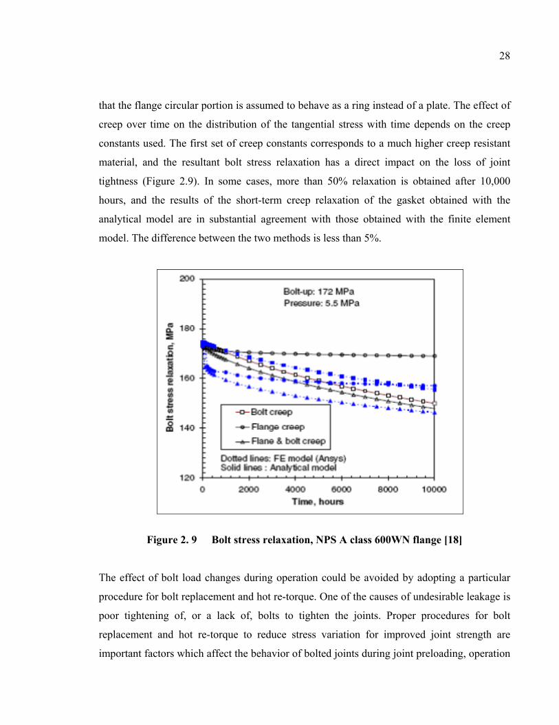
28
that the flange circular portion is assumed to behave as a ring instead of a plate. The effect of
creep over time on the distribution of the tangential stress with time depends on the creep
constants used. The first set of creep constants corresponds to a much higher creep resistant
material, and the resultant bolt stress relaxation has a direct impact on the loss of joint
tightness (Figure 2.9). In some cases, more than 50% relaxation is obtained after 10,000
hours, and the results of the short-term creep relaxation of the gasket obtained with the
analytical model are in substantial agreement with those obtained with the finite element
model. The difference between the two methods is less than 5%.
Figure 2. 9 Bolt stress relaxation, NPS A class 600WN flange [18]
The effect of bolt load changes during operation could be avoided by adopting a particular
procedure for bolt replacement and hot re-torque. One of the causes of undesirable leakage is
poor tightening of, or a lack of, bolts to tighten the joints. Proper procedures for bolt
replacement and hot re-torque to reduce stress variation for improved joint strength are
important factors which affect the behavior of bolted joints during joint preloading, operation

29
and retightening. Consideration of the space between bolts, the behavior of gaskets, and the
replacement of bolts during maintenance of connections, all of which affect the tightness
behavior of bolted flange connections, are objectives of this paper.
During bolt replacement and hot re-torque, the flange faces move and rotate relative to one
another, resulting in a change in bolt load during operation. An initial deformation produced
in the flange at the hub flange intersection causes an alignment problem for bolt bending,
resulting in leakage. This alignment problem becomes apparent when the flange is subjected
to operating conditions, and becomes even more serious when it is subjected to a
combination of loading conditions [18]. This effect is worsened by adopting procedures such
as hammering and flogging, or retightening, which damage not only the flange joint but also
the equipment to which the joints are attached. Bolt replacement and hot re-torque change the
situation of the static loading regime, causing bolted flange joints to become prone to
leakage.
Although a few analytical results are available in the literature highlighting the stress
variation behavior in bolted flange joints during bolt replacement and hot re-torque, no
assessment of the potential risks of leakage due to load change is available. Therefore, it
would be interesting to develop a theoretical approach to this problem that could be used to
recommend a procedure for bolt replacement and hot re-torque, ensuring that a joint is tight
and leakage is minimized.
2.6 Existing model of bolt spacing
2.6.1 Winkler hypothesis
In the assembly of flanges, bolts and gasket, the flange model is probably assumed to be a
circular beam resting on an elastic foundation. The analysis of the bending of flanges on a
gasket (elastic foundation) is developed based on the Winkler hypothesis that at every point,
the reaction forces of the gasket are proportional to the deflection of the flange at that point.

30
The vertical deformation characteristics of the foundation are defined through identical,
independent, closely spaced, discrete and linearly elastic springs. The constant of
proportionality of these springs is known as the modulus of subgrade reaction; this modulus
of subgrade reaction, which is assumed to be a mechanical representation of soil foundation,
was firstly introduced by Winkler, and is used as the primary input for rigid pavement
design. The Winkler model, which was originally developed for use in analyzing railroad
tracks, is very simple, but does not accurately represent the characteristics of many practical
foundations. Its most significant deficiency is that a displacement discontinuity appears
between the loaded and the unloaded part of the foundation surface. So far, the problem of
the beam resting on an elastic foundation has been discussed, assuming that the foundation
follows Winkler’s hypothesis [19].
2.6.2 Volterra’s model
The flange bending moment is a consequence of axial loads on bolts. The flange model is
probably assumed to be a model of a circular beam on an elastic foundation. Volterra
calculated the deflection of circular beams resting on an elastic foundation and loaded by
symmetrical, concentrated forces acting perpendicular to the plane of original curvature of
the beam and at an angular distance 2Ω (an angular distance from one bolt to the next).
Volterra’s model [19] is based on the reduction of the two Saint-Venant equations (3.1):
1
(3.1)

31
Figure 2. 10 Angular position between two bolts
where
θ twist rotation
J torsional moment of area
Gf flange shear modulus
Pb bolt force
R curve beam radius
2Ω angular distance between one bolt and the next
u axial flange displacement (mm)
s flange circumferential distance at gasket reaction position (mm)
and if
RIE
c
Ru
nf=
=
1
η
(3.2)
R

32
nf
nf
b
nf
f
IER
IERP
IEJG
4
2
θλ
υ
μ
=
=
=
(3.3)
Then equation (3.1) becomes:
t
n
Mdd
ddc
Mddc
=
+
=
−
αη
αθμ
αηθ
1
2
2
1
(3.4)
where the angle Ω is measured from the bisector of the angle between two points of loading,
and the equilibrium equations must be satisfied:
0
0
12
2
=Ω−−
=−
ηαα
α
cd
dMd
Md
Md
dMt
tn
nt
(3.5)
The boundary conditions are:
)()(
)()(
Ω−=ΩΩ−=Ω
ηηθθ
ucd
dMd
dMd
dd
dd
dd
dd
dd
d
xx 1
2
2
2
2
)()(
)()(
)()(
)()(
=Ω−ΩΩ
Ω−=Ω
Ω−=Ω
Ω−=Ω
−+
αα
ηα
ηα
θα
θα
ηα
η
(3.6)

33
The solution of Eqs. (3.4) and (3.5) with the above boundary conditions gives the following
expressions: [23]
(3.7)
where 23 13 12 2 2
12 2 2
(3.8)
with
9 1 272 27 1 9 1 274
1 1 272 27 1 9 1 274
(3.9)
The constants C1, C2, . . . and C12 are defined by the expressions: υ2 ∆ Ω 1

34
υ 2 2 1 3 2 Δ 1 4 Δ
υ 2 2 1 3 2 Δ 1 4 Δ
1
1 12 1 2 1 1 2
1 12 1 2 1 1 2
1 1
2 1 1 4
2 1 1 4
(3.10)
And the constants Δ1, Δ2, and Δ3 are defined by the following expressions:
Δ 3 4 1
∆ 4 ∆ Ω Ω Ω Ω 2 Ω 2 Ω
∆ 4 ∆ Ω Ω Ω Ω 2 Ω 2 Ω
(3.11)

35
Values of the functions θ/υ, η/υ, Mn/c1υ and Mt/c1υ are given in tables for some values of
the parameters λ and μ [19].
As indicated above, the foundation behaviors of a circular beam resting on an elastic
foundation are assumed to follow the hypothesis proposed in 1867 by E. Winkler [19]. The
hypothesis that a foundation has an elastic behavior may seem strange; as well, assuming that
the effect produced by a concentrated force on the foundation applies only at the point of
application is not exactly true since points close to the foundation are also affected [19]. The
Volterra method gives the bending deflection solution of a circular beam resting on an elastic
foundation in the cases of three, four, six, eight and twelve concentrated forces. However, the
method does not support a non-linear foundation behavior solution.
2.6.3 Roberts’s model
In 1950, Roberts [6] introduced a model to determine bolt spacing of bolted flange joints,
which was based on the theory of beam on elastic foundation. The solution utilized the
numerical summation method to solve the problem for gasket stress distribution in the
presence of a large number of bolts. Roberts presents criteria for maintaining 95% of the
gasket stress mid-span between bolts. The maximum bolt spacing is determined by the
equation:
√1 (3.12)
where
(3.13)
2.6.4 Koves’ model
Koves [12] applied the theory of straight beam on linear elastic foundation to develop a
closed form analytical solution that does not require numerical summation. The model is
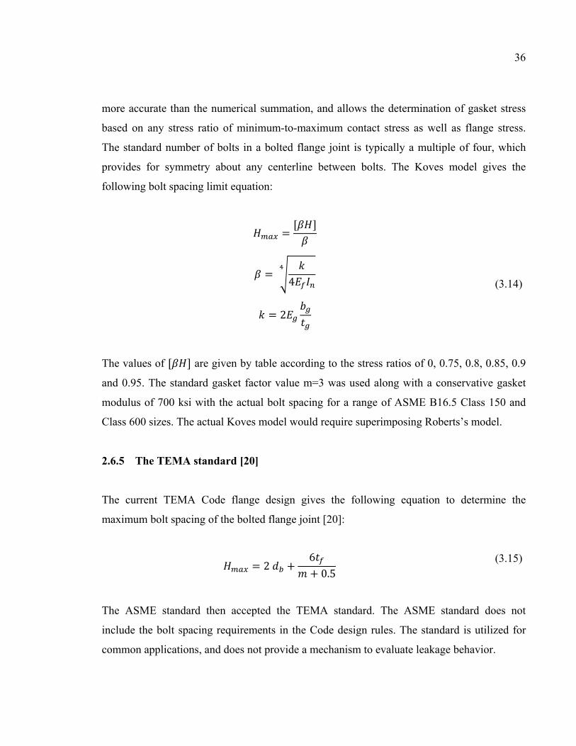
36
more accurate than the numerical summation, and allows the determination of gasket stress
based on any stress ratio of minimum-to-maximum contact stress as well as flange stress.
The standard number of bolts in a bolted flange joint is typically a multiple of four, which
provides for symmetry about any centerline between bolts. The Koves model gives the
following bolt spacing limit equation:
4
2
(3.14)
The values of are given by table according to the stress ratios of 0, 0.75, 0.8, 0.85, 0.9
and 0.95. The standard gasket factor value m=3 was used along with a conservative gasket
modulus of 700 ksi with the actual bolt spacing for a range of ASME B16.5 Class 150 and
Class 600 sizes. The actual Koves model would require superimposing Roberts’s model.
2.6.5 The TEMA standard [20]
The current TEMA Code flange design gives the following equation to determine the
maximum bolt spacing of the bolted flange joint [20]:
2 6 0.5 (3.15)
The ASME standard then accepted the TEMA standard. The ASME standard does not
include the bolt spacing requirements in the Code design rules. The standard is utilized for
common applications, and does not provide a mechanism to evaluate leakage behavior.
37
Because information is lacking regarding an accurate design procedure, an analytical
approach to solve the bolted flange joint problem should be developed. The analytical
solution of the initial bolt-up and pressurization of the joint may be satisfied with both linear
and non-linear foundation behavior. An analytical model supporting a design procedure
based on an investigation of the gasket contact stress distribution which may cause leakage of
the joint will be proposed in this study. This model is limited to the raised face flange type
only.
2.7 Objectives of the study
There are several methods used in calculating bolted joints, and they all concentrate on
calculating stress and strain as well as other factors, such as the influence of temperature,
relaxation, etc., on the connection. Until now, there has been no method for identifying the
potential risks of leakage of a bolted flange joint due to load change resulting from bolt
replacement and hot re-torque or bolt spacing of the connection. Following proper procedure
is important to maintaining leak tightness between bolts and to avoiding distortion of the
flange.
The objective of this study is to determine a theoretical approach for identifying and
analyzing the effects of initial bolt-up and pressurization on the bolted flange joints in order
to obtain a bolt spacing calculation solution according to different gasket contact stress
variation levels. This study will help the industrial practical services on designing,
maintaining and operating the technical pressure vessels and piping systems in special
applications and hot torquing. The target of the study is to investigate the solution of bolted
flange joint raised face type. Five flange sizes, namely, 4 inch, 16 inch, 24 inch, 52 inch and
120 inch Heat Exchanger (HE) flanges are investigated. The nominal flange dimensions are
shown in table 2.1.

38
Table 2. 1 Nominal flange dimensions
Flange
size
(in)
Af
in
(mm)
Bf
in
(mm)
C
in
(mm)
g0
in
(mm)
g1
in
(mm)
h
in
(mm)
4 in 10¾
(276)
3⅝
(92)
8½
(216)
¼
(6)
1
(25.4)
2
(50.8)
16 in 25½
(648)
16½
(419)
22½
(572)
¼
(6)
1
(25.4)
2
(50.8)
24 in 29½
(749)
23¼
(590)
27⅝
(701)
⅜
(10)
⅝
(16)
1½
(38)
52 in 58⅜
(1483)
51
(1295)
56¼
(1429)
⅝
(16)
1⅛
(29)
1¼
(32)
120 in 127
(3226)
120¼
(3055)
124½
(3162)
⅝
(16)
1⅛
(29)
3⅛
(32)
Flange size
(in)
tf
in
(mm)
nb db
in
(mm)
Ag
in
(mm)
N
in
(mm)
4 in 0.8(20)
0.9(23)
1(25.4)
1.1(28)
12
8
4
4
1(25.4)
1¼(32)
1½(38)
1½(38)
5⅜
(142)
½
(12.7)
16 in 1½(38)
1¾(48)
2(50.8)
2¼(57)
20,16,12,8,4
1(25.4)
1¼(32)
1½(38)
1½(38)
18¼
(464)
½
(12.7)
24 in 1
1½(38)
32,28,24,20
16,12,8
1(25.4)
1¼(32)
24½
(622)
½
(12.7)

39
1¾(48)
2(51)
1½(38)
1½(38)
52 in 2(51)
3½ (89)
5⅝(143)
5⅝(143)
72,68,64,60
56,52,48,44
40,36,32,28
24,20,16
12,8
1(25.4)
1¼(32)
1½(38)
1½(38)
53⅛
(1349)
½
(12.7)
120 in 3(75)
4½(114)
6½(165)
84,80,76,72
68,64,60,56
52,48,44,40
36,32,28,24
20,16,12,8
1(25.4)
1¼(32)
1½(38)
123
(3124)
½
(12.7)

CHAPTER 3
PROPOSED MODEL OF BOLT SPACING 3.1 Introduction
Bolted flange joints have three major components: flanges, bolts and gasket, which, in order
to work properly, must all be considered together as a system during the design process. The
performance and success of a reliable assembly depend on the quality and design procedure.
Additionally, the joint must be robust enough to prevent the acts of warping, distortion or
separating during service. Furthermore, service factors, such as thermal stresses, differential
expansion, external load, vibration and hot retorque must be considered on specific
applications. As a result, under steady-state operating conditions, leakage causes multiple
environmental and social problems.
3.2 Proposed model of bolt spacing
3.2.1 Proposed analytical model
The analytical model, which is limited to the raised face flange type only covers the contact
stress and the flange deformation of the bolted joints subjected to initial bolt-up and
pressurization (Figure 3.2). Determining an accurate design procedure for the bolted flange
joint requires a flexibility analysis of the bolted joint assembly. Figure 3.2 [21] shows the
flexibility interaction model used in this study. In this model, the flexibility of the flanges,
the gasket and the bolts, the flange deflections and rotations resulting from the initial bolt-up
and pressurization are considered. The model of our research can satisfy the technical
specifications of bolted flange joints using both hypothesis of linear and non-linear elastic
foundation behavior. The linear and non-linear elastic foundation behavior will be defined in
the next chapters.
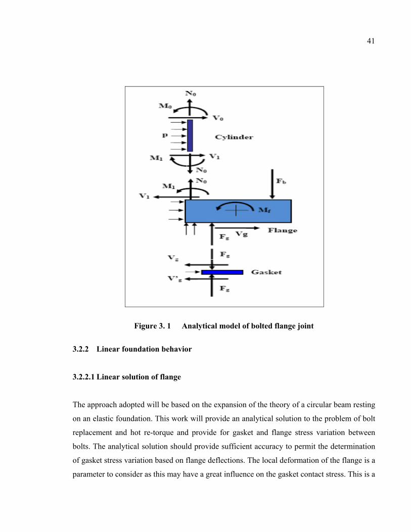
41
Figure 3. 1 Analytical model of bolted flange joint
3.2.2 Linear foundation behavior
3.2.2.1 Linear solution of flange
The approach adopted will be based on the expansion of the theory of a circular beam resting
on an elastic foundation. This work will provide an analytical solution to the problem of bolt
replacement and hot re-torque and provide for gasket and flange stress variation between
bolts. The analytical solution should provide sufficient accuracy to permit the determination
of gasket stress variation based on flange deflections. The local deformation of the flange is a
parameter to consider as this may have a great influence on the gasket contact stress. This is a

42
proposal of an analytical model to simulate the mechanical behavior of a bolted gasketed
joint and to determine the contact stress distribution in circumferential directions.
Considering an element of the flange (assumed to be a circular beam), limited by two
infinitely close cross-sections which are distant of ds, subjected to loads as shown in Figure
3.3.
Figure 3. 2 Infinitesimal element model of flange – linear foundation behavior
The equations for equilibrium must be satisfied with the following expressions:
• The equilibrium of forces along axis n, b and t:

43
0
2 2 2 2 2 cos 2 0
2 2 2 2 2 2 0
(3.16)
where ; 2 1 ; 2 2 0
The solution of the above equations yields:
(3.17)
• The equilibrium of moment around axis n, b and t:
2 2 2 2 2 2 2 2 2 2 2 2 0
44
2 2 2 22 2 2 2 2 0
2 2 2 2 2 2 2 0
(3.18)
The solution of the above equations yields:
2
(3.19)
The value of the ring bending moment per unit length qn is zero (qn = 0). The bending
rotation β is defined by the following expression: (3.20)
The following expression should be satisfied:
1 1
(3.21)

45
Assuming that:
• y1 = u: flange displacement,
• y2 = β: bending rotation,
• y3 = θ: twist rotation,
• y4 = Vb: shear force,
• y5 = Mn: bending moment,
• y6 = Mt: flange torsional moment.
The behavior of a circular beam resting on an elastic foundation may be expressed as:
2 2
(3.22)
The boundary conditions are:
Ω Ω Ω Ω Ω Ω Ω Ω Ω Ω Ω Ω Ω Ω Ω Ω
(3.23)

46
Ω Ω Ω Ω
Ω ∆ Ω ∆
3.2.2.2 Eigenvalues and eigenvectors method to solve the problem
When the flange is subjected to initial bolt-up and pressurization, the flange moment per unit
circumference Mf is defined by the equation:
2 2 2 16 (3.24)
In the case of initial bolt-up, the flange moment per unit circumference Mf is obtained by the
expression:
2 (3.25)
The torsional constant J is determined by [18]:
3 1 192 2 (3.26)
The moment inertia of area is given by:
24 (3.27)
The foundation constant represented by the gasket stiffness is given by:

47
2 2ΔΔ (3.28)
where ΔSg/ΔDg is the slope of the stress versus displacement graph assumed to be linear in
the operating range of the gasket stress.
Noting that:
• qn = 0: ring bending moment per unit length,
• qb = Mf: flange moment per unit length,
• Pb = Fb/2πC: ring axial force per unit length.
The behavior of a flange in bolted flange joints may be shown by the following expression:
2 2
(3.29)
The above differential equation system [22] may be written in the matrix form as follows:

48
0 1 0 0 0 00 0 1 0 1 00 1 0 0 0 10 0 0 0 00 0 0 1 0 1
2 0 0 0 1 0
00020
(3.30)
or in the following form:
(3.31)
The system equation which governs the flange in bolted flange joints is a non-homogeneous
differential equation. The homogeneous differential equation is:
(3.32)
To solve the homogeneous differential equation, the eigenvalue method is used to calculate
the eigenvalues and eigenvectors. The eigenvalues λ which are the scalar proportionality
factors of matrix Ap were denoted by the expression:
Δ 0 (3.33)
The eigenvectors χ which are the solutions corresponding to the eigenvalues of matrix Ap
were shown by the following expression:
0 (3.34)

49
where the identify matrix I is given by:
1 0 0 0 0 00 1 0 0 0 00 0 1 0 0 00 0 0 1 0 00 0 0 0 1 00 0 0 0 0 1
(3.35)
The solution of the homogeneous differential equation gives the following expression of
eigenvalues λ as:
0 0 0 0 00 0 0 0 00 0 0 0 00 0 0 0 00 0 0 0 00 0 0 0 0
(3.36)
(3.37)
And the expression of eigenvectors χ is:

50
0 0 0 0 0 0 0 0 0 00 0 0 0 0 0 0 0 0 00 0 0 0 0 0 0 0 0 0
(3.38)
(3.39)
Eigenvalue λ and eigenvector χ of matrix Ap are complex values. The real valued solution of
the above homogeneous differential equations gives the following expression:
(3.40)
where b1, b2, c1, c2, c3, d1, d2, d3 and d4 are constants which depend on the parameters of the
flanges in bolted flange joints.
The Matlab programming [18] software, supported by the function [Vp, Dp] = eig(Ap) was
used to determine the eigenvectors and eigenvalues.
Assuming that Mp is a fundamental matrix, Mp is satisfied with the following expression:

51
(3.41)
0 : evaluation of Mp at the position of α = 0 (3.42)
The general solution of the problem gives the following expression [22]:
0 (3.43)
where Y0 corresponds to vector Y(α) at the mid-bolt position (α=0):
(3.44)
The boundary conditions are:
Ω Ω Ω Ω Ω Ω Ω Ω Ω Ω Ω ∆ Ω ∆ 2
(3.44)

52
Applying the boundary conditions above, Y0 is determined by the expression:
(3.45)
Where
Ω 0 , Ω 0 , ;Ω 0 , Ω 0 , ;Ω 0 , Ω 0 , ;Ω 0 , Ω 0 ,Ω 0 , Ω 0 , ;Ω 0 , Ω 0 ,Ω 0 , Ω 0 , ;Ω Δ 0 , Ω Δ 0 ,Ω Δ 0 , Ω Δ 0 , ;
(3.46)
and

53
Ω , Ω , ; Ω ΩΩ , Ω , ; Ω ΩΩ , Ω , ; Ω Ω
Ω , Ω , Ω ΩΩ , Ω , ; Ω ΩΩ , Ω , Ω Ω
Ω , Ω , ; Ω Ω
2 Ω ∆ , Ω ∆ , Ω ∆Ω ∆Ω ∆ , Ω ∆ , ;Ω ∆Ω ∆
(3.47)
The Matlab programming [23] software supported by the functions [V, D] = eig(A), based on
the eigenvalues and eigenvectors method was used to solve the above system of equations.
3.2.2.3 Finite element model
Two bolted flange joints used in pairs were studied, one a 24-inch HE flange and the other a
52-inch HE flange. To validate the analytical model, two 3-dimensional FE models were built
and run on ANSYS [24]. Because of the symmetry with respect to the plane that passes
through the gasket mid-thickness and the bolts as well as to the repeated bolt load, it is only
necessary to model an angular portion bounded by two longitudinal planes located between
bolts. Symmetry could have been used to halve the model again through the bolt center-line.
It should be noted that the analytical model developed can be used together with FEM to
investigate the effect of bolt bending due to flange rotation. The initial bolt-up is applied by
54
imposing an equivalent axial displacement on the bolt mid-plane nodes to produce the target
initial bolt-up stress at 276 MPa. Because the axial displacement is very small, it does not
alter the symmetry. A convergence criterion based on the final equivalent axial displacement
was used to refine the mesh. An isoperimetric 8-node solid element SOLID185 type mesh
was generated for the 3-D modeling of solid structures. It is defined using eight nodes each
having three degrees of freedom: translations in the nodal x, y, and z directions. The element
is defined by eight nodes and orthotropic material properties. The bolts are also modeled
using these elements and coupled to the adjacent nodes on the upper surface of the flange. In
fact, the meshing was refined until the change in the contact pressure dropped to less than
1%. Because of the symmetry, only half of the gasket thickness was modeled.
The above approach was used to study the contact stress level unbalance around the flange
when the bolts are subjected to initial tightening. The study compares contact stress
distribution variations, using an analytical model developed based on the theory of rings on
an elastic foundation, to those given by the finite element model and the simple beam on
elastic foundation model developed by Koves [12]. Two bolted flange joints used in pairs
were studied, one a 24-inch (600 mm) heat exchanger (HE) flange, and the other a 52-inch
(1300 mm) HE flange. This study is developed in a bid to help limit the degree of load
increase in hot torquing or the maximum number of bolts to be replaced at a time and
identify those flanges for which the bolt cannot be replaced during operation. The results
were presented at the 16th International Conference on Nuclear Engineering; ICONE16,
Paper No ICONE16-48634, ASME, Orlando, Florida, USA, 2009, and the paper, whose
contents are introduced in the fourth chapter, was published in the Journal of Pressure Vessel
Technology, ASME, 2011, Vol. 133(4) 041205, 10pp..

55
3.2.3 Non-linear foundation behavior
3.2.3.1 Non-linear solution of flange
Half the bolted flange joint is modeled by a simple circular ring that rests on a non-linear
elastic foundation. The three bending and twisting moments and the three forces generated by
the initial tightening are considered. The analytical development is similar to that of the
theory of circular beam on an elastic foundation [16].
Figure 3. 3 Infinitesimal element model of flange – non-linear foundation behavior
Consider an element of the flange ring assumed to be a circular beam supported by the gasket
taken as the nonlinear elastic foundation, with two cross-sections infinitely close to each

56
other at a distance ds, with the rotation centers, Gr and Gr’, subjected to the loading shown in
Fig. 3-4. The reaction of the gasket is assumed to be non-linear of the form:
(3.48)
The equilibrium of the forces in the 3 directions reduces to:
(3.49)
The equilibrium of the moments on the 3 axes reduces to:
2
(3.50)
The differential equation system which governs a circular beam on an elastic foundation may
be written in the following expression:
(3.51)

57
2 2
or in the matrix form as follows:
00020
(3.52)
Where
0 1 0 0 0 00 0 0 00 0 0 00 0 0 0 00 0 0 1 00 0 0 0
(3.53)
Note that matrix Ap is not constant, and is a function of flange displacement y1 and as a
result, the equations system above is non-linear and requires the use of non-linear methods to
resolve the problem.

58
3.2.3.2 Runge-Kutta method to solve the problem
The Kunge-Kutta method uses the Euler formula, described as follows [25]:
∆ , ∆ (3.54)
The modified Euler method is defined by: ∆ 12 , , ∆ (3.55)
The Runge method is based on the third approximation of : ∆2 , 12 , ∆ ∆
(3.56)
In Kutta’ s third-order method, the three estimates of ∆ are:
∆ , ∆ (3.57) ∆ is used in Euler’s method,
∆ ∆ , ∆ ∆ 0 1 (3.58)
∆ is used in Runge’s method; and
∆ ∆ , ∆ ∆ ∆ 0 , 1 (3.59)
Finally, the value which is actually used for ∆ in the calculation of is taken to be:
∆ ∆ ∆ ∆ (3.60)

59
where , , , , , are parameters which are to be chosen to ensure the highest
possible accuracy in estimating ∆ .
The Runge-Kutta method was used to solve the above differential equation. Consider the
differential equation described as follows [26]:
, ; (3.61)
Applying an equivalent numerical procedure, it means that the local discretization errors are
each proportional to the same power of ∆ . The classical Runge-Kutta formula is equivalent
to a five-term Taylor formula:
∆ ∆2! ∆3! ∆4!
∆ ∆ ∆2! ∆3! ∆4!
(3.62)
The Runge-Kutta formula involves a weighted average of values of f α, y taken at different
points in the interval α α α . It is given by:
∆ 2 2 (3.63)
where , ∆ , ∆ (3.64) 12 ∆ , 12 ∆ ∆ , ∆
The sum 2 2 can be interpreted as an average slope.
60
Note that:
• is the slope at the left end of the interval,
• is the slope at the midpoint using the Euler formula, to go from to ∆
,
• is a second approximation of the slope at the midpoint; the slope is gone from to ∆ ,
• is the slope at , using the Euler formula to go from t ∆ .
The Runge-Kutta formula is more complicated than all the others. The Runge-Kutta method
provides an effective way to solve the differential equation by numerical method. It should be
noted that this is a very accurate formula, and furthermore, that no partial derivatives of
function f α, y need to be computed.
The Matlab programming [23], software supported by the functions ODE45 based on the
Runge- Kutta method, was used to solve the above system of equations.
3.2.3.3 Finite element model
To validate the analytical model, two 3-dimensional numerical FEM models of the two
bolted joints, namely, 52 in and 120, in the HE flange, were built and run on the ANSYS
finite element software [24]. Because of the symmetry with the plane passing through the
gasket mid-thickness and the bolts as well as the repeated loads equally spaced around the
circumference, it is only possible to model an angular portion that passes through two
longitudinal planes located at two adjacent bolts. A uniform simultaneous load is applied to
all bolts by imposing an equivalent axial displacement to the bolt mid-plane nodes to produce
the target initial bolt-up stress. Based on the analytical solution described above, flange
displacements and gasket contact stresses were calculated at the position of gasket reaction
diameter G. The initial bolt-up load was 276 MPa. The Young’s modulus of the flange and

61
bolts were assumed to be 207 GPa. The experimental data for the corrugated metal sheet
(CMS) gasket was applied both for the analytical solutions and the FEM. A mesh of
isoperimetric of SOLID185 type 8-node solid elements was generated for the 3-D modeling
of solid structures. The bolts were also modeled using these elements, and coupled to the
adjacent nodes on the upper surface of the flange. Because of the symmetry, only half of the
gasket thickness is modeled.
The non-linear foundation behavior solution is an extension of the linear foundation behavior
in which an analytical solution based on the true gasket non-linear behavior is developed.
The study focuses on the distribution of the gasket contact stress of two large diameter heat
exchanger flanges, one 52 inches and the other, 120 inches. The non-linear gasket behavior
solution is compared to the FEA and the linear gasket behavior solution for evaluation and
comparison. The results were presented at the 2010 ASME - PVP Conference, Bellevue,
Washington, July 2010, Paper No PVP2010-26001. The contents were ranked as one of the
Finalist Papers of the Conference. The presentation was awarded as the Winner of the
Conference prize. This paper was accepted by the Journal of Pressure Vessel Technology in
June 2011. These contents will be introduced in the fifth chapter.
3.2.4 Linear regression model of bolt spacing
The linear foundation behavior problem was solved in order to get flange displacements, and
as a result, the gasket contact stresses were obtained. The bolt spacing according to different
correlative maximum contact stress variations and the average contact stress of the joint were
determined [27-30]. The relationship between the bolt spacing, the flange sizes (Af, Bf, and
tf), the gasket Young’s modulus and the flange Young’s modulus was given by a linear
regression model. The least squares method is typically used to estimate the regression
coefficients in a multiple linear regression model.
We assumed that H = bolt spacing; x1 = (Af – Bf); x2 = (Eg/Ef); x3 = tf. The linear regression
model was created based on the 75 observations on three different flange thicknesses for 5

62
flange sizes (4-inch, 16-inch, 24-inch, 52-inch and 120-inch HE flanges) on five gasket
compression modulus values (207, 276, 345, 414 and 483 MPa) and one flange Young
modulus value (21 GPa). The linear regression model equation that might describe this
relationship is [31]:
1,2, … ,75 (3.65)
1,2, … ,
where aj is a regression coefficient and is the error.
The above equation may be written in matrix notation as:
(3.66)
Where
... 11 . . . .. . . .. . . .1
(3.67)
, and ...
The least squares estimator of is:
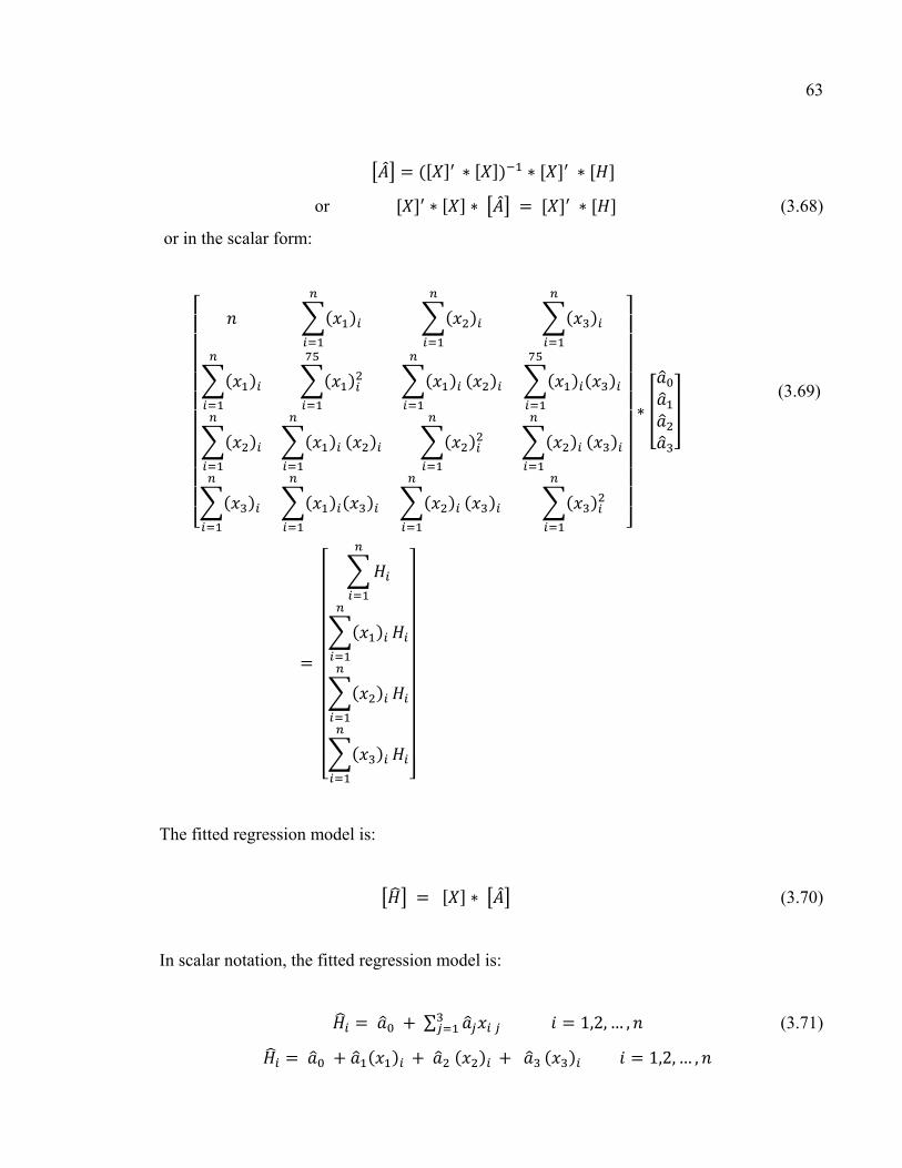
63
or (3.68)
or in the scalar form:
(3.69)
The fitted regression model is:
(3.70)
In scalar notation, the fitted regression model is:
∑ 1,2, … , (3.71) 1,2, … ,
64
And the vector of residuals is denoted by:
(3.72)
The Matlab programming [23] software was used to fit the regression model to the
observation data.
The linear regression theory was applied to study five bolted flange joints (4-inch, 16-inch,
24-inch, 52-inch and 120-inch) HE flange. Based on the analytical solution described above,
flange displacements and gasket contact stresses were calculated at the position of gasket
reaction diameter G. The difference in percentage between the maximum contact stress
variation and the average contact stress of the joints was stated by the analysis at the 2%, 5%,
10% and 15% levels. The linear regression model was created with the bolt spacing function
according to variables of flange size (x1 = Af – Bf), gasket and flange Young’s modulus (x2 =
Eg / Ef) and flange thickness (x3 = tf) as a result of the analysis. The bolted flange joints bolt
spacing fitted regression model was determined by using the Matlab environment. Our study
focuses on the bolt spacing solution of five bolted flange joints as mentioned above, with
respect to the gasket Young’s modulus (207, 276, 345, 414 and 483 MPa), ranging from
Teflon based to fiber reinforced sheet gaskets. These contents were submitted to the
International Journal of Pressure Vessel and Piping, 2011, and they will be introduced in the
sixth chapter.

CHAPTER 4
PAPER 1: EFFECT OF BOLT SPACING ON THE CIRCUMFERENTIAL DISTRIBUTION OF
GASKET CONTACT STRESS IN BOLTED FLANGE JOINTS
Tan Dan Do1, Abdel-Hakim Bouzid, Thien-My Dao3
1 Ph. D. student, Mechanical Engineering Department, École de technologie supérieure, 1100 Notre-Dame St. West, Montreal, Quebec, H3C 1K3
email: [email protected]
2 ASME Fellow, Professor, Mechanical Engineering Department, École de technologie supérieure, 1100 Notre-Dame St. West, Montreal, Quebec, H3C 1K3
email: [email protected]
3 Professor, Mechanical Engineering Department, École de technologie supérieure, 1100 Notre-Dame St. West, Montreal, Quebec, H3C 1K3
email: [email protected]
Presented at the 16th International Conference on Nuclear Engineering , ICONE 16,
Paper No ICONE16-48634, ASME, Orlando, Florida, USA, 2009.
Published in the Journal of Pressure Vessel Technology, ASME, 2011, Vol. 133(4)
041205, 10 pp.
Abstract
Bolted flange joints are part of pressure vessel and piping components and are used
extensively in the chemical, petrochemical and nuclear power industries. They are simple
structures and offer the possibility of disassembly which make them attractive to connect
pressurized equipments and piping. In addition of being prone to leakage, they often require
maintenance while in operation in which case the bolts are either retightened as in hot
torquing or untightened to be replaced. Although costly shutdown are avoided, such a
maintenance work exposes the operator to a potential risk because the bolt load alteration can
produce a gasket load unbalance which results in a local gasket contact stress to drop below
66
some critical value causing major leak and hence jeopardizing the life of the operator. This
paper addresses the issue of the contact stress level unbalance around the flange when the
bolts are subjected to initial tightening. This study is developed for the purpose of helping
limit the degree of load increase in hot torquing or the maximum number of bolts to be
replaced at a time and identify those flanges the bolt of which cannot be replaced in service.
Keywords: bolted flange joints, leakage, hot-torquing, gasket contact stresses
Résumé
L’assemblage de brides boulonnées fait partie des appareils à pression et des composantes de
tuyauterie largement utilisés dans l’industrie chimique, pétrochimique et dans l’énergie
nucléaire. Les brides boulonnées sont des structures simples offrant la possibilité d’être
démontées ce qui, aux yeux de plusieurs, est un attrait permettant de connecter d’autres
équipements sous pression et/ou de la tuyauterie. Toutefois et malgré cet attrait, elles sont
sujettes à des fuites et, le plus souvent, ont besoin de maintenance durant la période de
fonctionnement. Les boulons peuvent, par exemple, être resserrés selon un procédé de
serrage chaud et/ou desserrés afin d’être remplacés. De tels arrêts sont à prohiber car, ils
entraînent un accroissement des coûts et expose l’opérateur à des risques dus à la surcharge
subit par la bride. Cette surcharge pourrait introduire un déséquilibre au niveau du joint qui
aurait pour effet de réduire la valeur critique tolérée pour la contrainte de contact et
provoquer d’importantes fuites qui, le cas échéant, pourraient compromettre le vie de
l’opérateur. Cet article aborde la question relative à la pression de contact entrainant un
déséquilibre autour de la bride lorsque les boulons sont soumis à un serrage initial. Dans ce
papier, notre étude compare la variation de la distribution du stress via l’usage d’un modèle
analytique basé sur les fondements théoriques des anneaux élastiques à celles fournies par un
modèle utilisant la théorie des éléments finis et/ou une approche focalisant sur le recours à la
technique du "faisceau simple" développée par Koves en 2007. Ce papier est développé dans
l’optique d’aider à limiter l’augmentation de la charge de serrage à chaud et/ou le nombre
maximal de boulons pouvant être remplacé à un moment donné.
67
Mots-clés: brides boulonnées, fuites, serrage à chaud, contrainte de joint de contact
Nomenclature
α angle position (rad)
β bending rotation (rad)
θ flange twist rotation (rad)
A flange outside diameter (mm)
Ag gasket outside diameter (mm)
b flange width equals to (A-B)/2 (mm)
B flange inside diameter (mm)
Bg gasket inside diameter (mm)
C bolt circle (mm)
D0 diameter of flange centroïd (mm)
Dg gasket displacement (mm)
d, db nominal bolt diameter (mm)
Ef Young’s modulus of flange (MPa)
Eg Young’s modulus of gasket (MPa)
Fb total bolt force (N)
Fg gasket force (N/mm)
Fn axial force per unit length (N/mm)
g0,g1 hub small and big end thickness (mm)
G gasket reaction diameter (mm)
Gf shear modulus (MPa)
h0 hub length (mm)
H bolt spacing (mm)
J torsional moment of area (MPa)
K elastic foundation constant (MPa)
Mb ring bending moment (N.mm)

68
Mf flange twisting moment (N.mm/mm)
M0 discontinuity edge moment (N.mm/mm)
Mn ring bending moment (N.mm)
Mt ring twist moment (N.mm)
nb bolt number
N0 axial force per unit length (N/mm)
Nt ring axial force (N)
Pb ring axial force per unit length (N/mm)
qb ring twisting moment per unit length (N.mm/mm)
qn ring bending moment per unit length (N.mm/mm)
Sg gasket stress (MPa)
tf flange thickness(mm)
u axial flange displacement (mm)
V0, V1 discontinuity edge force (N/mm)
Vb, Vn ring axial shear force (N)
yi variables
Acronyms
ASME
HE
American Society of Mechanical Engineers
Heat Exchanger

69
4.1 Introduction
Bolted flange connections have important applications as part of pressure vessels and piping
equipment not only in refineries but also in chemical and nuclear industries. However, with
the need for more onerous service duties, as found typically in the oil and gas exploitation
industry, there is an increasing demand for higher operational pressures and temperatures as
the industry seeks for more efficiency. Leakage generates costs due to maintenance, loss of
revenue and sometimes penalties for none compliance with environmental laws.
Presently, a great effort is put worldwide towards reducing leakage to minimum acceptable
levels by introducing new tightness based design procedures of bolted flange joints. Because
the current ASME flange design procedure [1] is not based on leakage, it is difficult to assess
the level of safety during operation. Even though considerable research work has already
been undertaken in North America under the auspices of PVRC for the last 25 years with the
aim of understanding and solving the leakage problems of bolted flange gasketed joints, there
is no consensus among the ASME code committee to adopt a more realistic and modern
flange design procedure such as the European EN1591 standard [2].
Investigations related to the various causes such as inadequate tightening of bolts, external
bending loads, temperature related effects and bolt spacing issues are just a few to name.
Experiments show that the leak rates of bolted flange joints are not only dependent on the
average contact stress, but also on the way the stress is distributed across the gasket width.
The latter is a function of flange thickness, flange rotation, bolt spacing and gasket stiffness.
While in operation, it is sometimes required to retighten the bolts to compensate for
relaxation (hot torquing) or untighten the bolts for replacement. Such manipulations can
cause the gasket contact stress to unload locally to critical levels which results in important
leaks and consequently can harm the operator. It also may result in high local gasket contact
stresses which can crush the gasket causing important leaks. Because of the flexibility of the
flange ring and the concentrated nature of bolt force, the axial movement of one flange
relative to the other is not uniform across the gasket contact area. The displacement or

70
compression between two bolts is much lower than that at the bolt position resulting in a
smaller gasket contact stress. Furthermore, during bolt replacement and hot re-torque, the
flange faces move and rotate relative to one another resulting in a change in the contact stress
of the gasket during operation. The amount of gasket compression and its variation
circumferentially depends on several factors among which are bolt spacing and flange
thickness. Inadequate contact pressure applied at the mid location between bolts may result in
leakage. This effect may be minimized by a proper design which incorporates an adequate
combination of bolt spacing, flange ring thickness and gasket materials.
There are several methods used in calculating bolted joints. All of the methods concentrate
on calculating stress and strain as well as other factors such as the influence of temperature
and relaxation on the connection. Up to now there has been no method to identify the
potential risks of leakage of a bolted flange joint due to load change resulting from bolt
replacement and hot re-torque or bolt spacing of the connection. Since the early work of
Water et al. [3,4] in the late thirties on bolted joints, there has been little research on the
effect of bolt spacing on the circumferential distribution of the gasket contact stress and the
leakage tightness of bolted flange connections. Taylor Forge [5] has developed a rule on bolt
spacing which was adopted by TEMA [6] but not ASME [1]. The maximum spacing between
bolt centers when exceeding 2db+t is determined by the expression:
max
62
0.5ft
H dm
= ++
(4.1)
Other approaches have been applied for joints with metal to metal contact [7,8]. Roberts [9]
developed a numerical summation approach to get maximum bolt spacing by considering the
flange to behave as a straight beam on elastic foundation. In 1975, Kilborn et al. [10] carried
out a study on the spacing of bolts in flanged joints. The maximum allowable bolt spacing for
flange sealing occurs when the pressure at the point midway between the bolts has zero
value. Any further increase in bolt spacing will cause the contact pressure to decrease
considerably with possible separation of the flanges and leakage of the joint. The
assumptions in this analysis are that the flanges are flat and that the bolt spacing and flange

71
width are small in comparison to the bolt pitch circle diameter. The curvature of the flange is
therefore neglected, and the results apply to straight flanges, and only approximately to
flanges of large diameter. In 2007, Koves [11] expands the approach used by Roberts based
on beam on elastic foundation to develop a closed form analytical solution that does not
require numerical summation.
This paper presents an approach based on the expansion of the curved beam on elastic
foundation theory [12]. The analytical solution provides an evaluation of the circumferential
distribution of gasket contact stress based on flange deflections. Linear gasket behavior is
considered in the analysis. The local deformation of the flange may be a parameter to
consider as this may have a great influence on the gasket contact stress. To validate the
analytical model three-dimensional numerical finite element models were developed. The
general purpose finite element computer program ANSYS 9.0 is used to simulate the three
dimensional behavior of bolted flange joints.
4.2 Theoretical analysis
4.2.1 Analytical model
The Analytical model shown in Fig. 4.1 treats the deformations and contact stresses of the
bolted joints of Fig. 4.2 subjected to the loading generated during initial tightening and
pressurization. The flange ring is treated using the theory of circular beam on elastic
foundation [12, 13].
In the case of initial bolt-up, the flange moment per unit circumference Mf is obtained by the
expression:
0 2π− =
b
fF C GMD (4.2)
Considering an element of the flange assumed as a circular beam supported by the gasket
acting as the elastic foundation, limited by two cross sections infinitely close to each other by

72
a distance ds, the rotation centers of which are Gr and Gr’ subjected to loads as shows in Fig.
4.1. The reaction of the gasket is supposed linear and equal to K u. The equilibrium of forces
in the 3 directions reduces to:
(4.3)
The equilibrium of moments about the 3 axes reduces to:
2
(4.4)
The bending moment Mn and the twist moment Mt can be expressed in terms of the
displacement v and the section rotation θ as [12]:
1 1
(4.5)
The second and polar moments of area are given by:
3
ln24
fn
o
t AID B
= (4.6)

73
3
5
1921 tanh
3 2f f
f
bt t bJb t
ππ
= −
And the foundation constant represented by the gasket stiffness is given by:
2
2g g
g g
E N S NK
t DΔ
= =Δ
(4.6)
Where ∆∆ is the slope of the stress versus the displacement graph assumed to be linear in
the operating range of the gasket stress.
As in beam theory the slope can be expressed as the derivative of the displacement then:
(4.7)
Therefore:
n f ndM E I
R dsθ β = −
β θ = +
t fdM G J
R ds
(4.8)
Substituting Eqs.(4.9) into (4.3) and (4.4) , noting that qn = 0 , qb = Mf and Pb = Fb/2πC and
assuming that y1 = v (flange displacement); y2 = β (bending rotation); y3 = θ (twist rotation);
y4 = Vb (shear force); y5 = Mn (bending moment) ; y6 = Mt (twist moment); the following
expressions must be satisfied:

74
'1 2y y β= =
' 3 52
n
f n f n
y y MyR E I R E I
θ= − = −
' 6 t23
f f
y Myy
G J R G J R
β= − = −
' 65 4
tb
y My y VR R
= − + = − +
' 5 06 1
0
( )
2fy D G Gy M KyR D
−= + +
(4.9)
The above differential equation system which governs a circular beam on elastic foundation
[12] may be written in the matrix form as follows:
0 1 0 0 0 00 0 1 0 1 00 1 0 0 0 10 0 0 0 00 0 0 1 0 1
2 0 0 0 1 0
00020
(4.10)
or in the following form:
'pY A Y g = +
(4.11)

75
4.2.2 Flange working examples
Matlab 7.0.4 software was used to solve the above system of equations. Two bolted flange
joints used in pairs were studied; one is 24 in HE flange and the other is a 52 in HE flange.
Based on the analytical solution as described above, flange displacements and rotations were
calculated at the position of gasket reaction diameter G. The initial bolt-up load was 276
MPa. The Young modulus of flange and bolts are assumed as 207 MPa. For 24 in HE flange,
the compression modulus of the gasket was made to vary as 3.5, 6.9 and 20.7 GPa. The
dimensions of the two flanges are shown in Table 4.1.
4.3 Finite element model
To validate the analytical model, two 3D-dimensional numerical FE models were built and
run on ANSYS [15]. These are the two bolted joints described above. Because of symmetry
with respect to plane that pass through the gasket mid thickness and the bolts and also to the
repeated loading acting at the angular perpendicular direction, it is possible to model only an
angular portion that pass through the two longitudinal planes located between bolts as shown
in Fig. 3. The initial bolt-up is applied by imposing to the bolt mid-plane nodes, an
equivalent axial displacement to produce the target initial bolt-up stress.
4.4 Discussion
Figures 4.4 and 4.5 compare the results of the average contact stress distributions given by
the analytical model and the ones given by FEM and Koves [11]. Because of symmetry the
distribution is given for only half of the sector delimited between two adjacent bolts. The
comparison is shown for the 52 HE flange with two different flange thicknesses namely 143
mm and 89 mm. The gasket stiffness was also varied between 3.5 GPa and 20.7 GPa to cover
most existing gasket style. It can be said that, in general, the results compares quite well and
in particular the value at the maximum contact stress variation which is located exactly

76
between the bolts as one would expect. This value is well predicted at lower values of the
gasket stiffness.
Figures 4.4 to 4.8 show the results of the contact stress variation and its distribution in the
circumferential direction given by the analytical model and the ones given by Koves [11] for
half a sector delimited by two bolts for different number of bolts and flange thicknesses. The
analytical contact stress variations at the gasket reaction position are compared to investigate
the influence of gasket Young modulus Eg, flange thickness tf and number of bolts nb. The
results show that contact stress variation increases when Eg increases or tf and nb decrease.
The contact stress variation increases from 6% when Eg = 3.5 GPa to 26% when Eg = 7 GPa
for the 52 in. HE flange with tf = 89 mm and nb =24 bolts (Fig.4. 4). When the bolt number
is large (76 bolts), the contact stress variation is small. The contact stress variation increases
6 times when reducing nb from 48 to 24 bolts (Fig. 4.7). Similar results were found for the 24
in HE flange (Figs. 4.5 and 4.6) in that the contact stress variation increases up to 26%
because of the influence of Eg and nb.
Figures 4.9 to 4.12 show the results of the flange displacement variation and its distribution
in the circumferential direction given by the analytical model and the simple model by Koves
[11]. The variation increases when Eg and nb decreases. Figures 4.9 and 4.10 show flange
displacement variation of the 52 in HE flange while varying the three parameters tf (38 and
48 mm), Eg (2 and 3.5 GPa) and nb (16, 20 and 24 bolts). Figures 4.11 and 4.12 show flange
displacement variation of the 52 in HE flange while varying the three parameters tf (89 and
143 mm), Eg (2 and 7 GPa) and nb (24, 48 and 76 bolts).
Figures 4.13 to 4.16 show the results of the flange rotation variation and its distribution in the
circumferential direction given by the analytical model for different number of bolts and
flange thicknesses. Flange rotation at each point at gasket reaction position is compared with
the value of flange rotation at mid-bolt position to investigate its variation. Flange rotation
variation increases by decreasing of Eg and nb. Figures 4.13 and 4.14 shows flange rotation
variation of 52 in. HE flange on the effect of tf = 38 mm and 48 mm, Eg = 2 GPa and 3.5
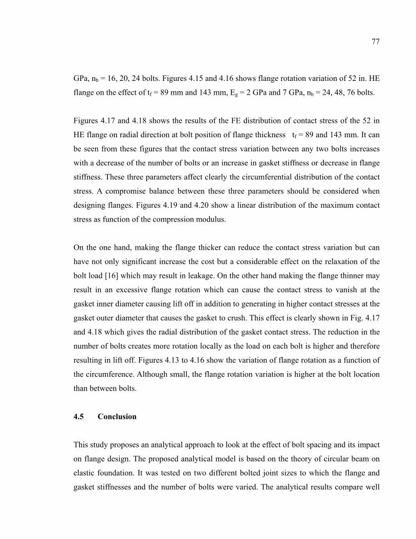
77
GPa, nb = 16, 20, 24 bolts. Figures 4.15 and 4.16 shows flange rotation variation of 52 in. HE
flange on the effect of tf = 89 mm and 143 mm, Eg = 2 GPa and 7 GPa, nb = 24, 48, 76 bolts.
Figures 4.17 and 4.18 shows the results of the FE distribution of contact stress of the 52 in
HE flange on radial direction at bolt position of flange thickness tf = 89 and 143 mm. It can
be seen from these figures that the contact stress variation between any two bolts increases
with a decrease of the number of bolts or an increase in gasket stiffness or decrease in flange
stiffness. These three parameters affect clearly the circumferential distribution of the contact
stress. A compromise balance between these three parameters should be considered when
designing flanges. Figures 4.19 and 4.20 show a linear distribution of the maximum contact
stress as function of the compression modulus.
On the one hand, making the flange thicker can reduce the contact stress variation but can
have not only significant increase the cost but a considerable effect on the relaxation of the
bolt load [16] which may result in leakage. On the other hand making the flange thinner may
result in an excessive flange rotation which can cause the contact stress to vanish at the
gasket inner diameter causing lift off in addition to generating in higher contact stresses at the
gasket outer diameter that causes the gasket to crush. This effect is clearly shown in Fig. 4.17
and 4.18 which gives the radial distribution of the gasket contact stress. The reduction in the
number of bolts creates more rotation locally as the load on each bolt is higher and therefore
resulting in lift off. Figures 4.13 to 4.16 show the variation of flange rotation as a function of
the circumference. Although small, the flange rotation variation is higher at the bolt location
than between bolts.
4.5 Conclusion
This study proposes an analytical approach to look at the effect of bolt spacing and its impact
on flange design. The proposed analytical model is based on the theory of circular beam on
elastic foundation. It was tested on two different bolted joint sizes to which the flange and
gasket stiffnesses and the number of bolts were varied. The analytical results compare well

78
with those of FEA and Koves [11]. The simplified model is based on a constant gasket
stiffness that represents the elastic foundation. This model has potential to be used to improve
bolt spacing designs and investigate the effect of in service bolt replacement and hot-
retorque. The thickness of the flange and the stiffness of the gasket have a great effect on the
stress distribution.

79
Table 4. 1 Nominal flange dimensions of 24 in. and 52 in. HE flange
Flange
size
(in)
A
in
(mm)
B
in
(mm)
C
in
(mm)
g0
in
(mm)
g1
in
(mm)
h0
in
(mm)
24 29½
(749)
23¼
(590)
27
(686)
⅜
(10)
⅝
(16)
1¼
(32)
52 58⅜
(1483)
51
(1295)
56¼
(1429)
⅝
(16)
¾
(19)
1¼
(32)
Flange size
(in)
tf
in
(mm)
nb db
in
Ag
in
(mm)
Bg
in
(mm)
24 1.5
(38)
1⅞
(48)
16
20
24
⅞
1¼
1½
24.5
(622)
23.5
(597)
52 3.5
(89)
5⅝
(143)
24
48
76
1
1¼
1½
53⅛
(1349)
52⅛
(1324)

80
Figure 4. 1 Infinitesimal element model of flange
Figure 4. 2 Loads in a bolted flange gasketed joint
Mb+
n
Gr
O
Mb
Vb Nt
Mt
Vn Mn Fn qn
Pb qb
dφ
Kv
R
GD0
G’
r
Vn+ Mt+ Nt+
Vb+
Mn+
Gr
O
b
t
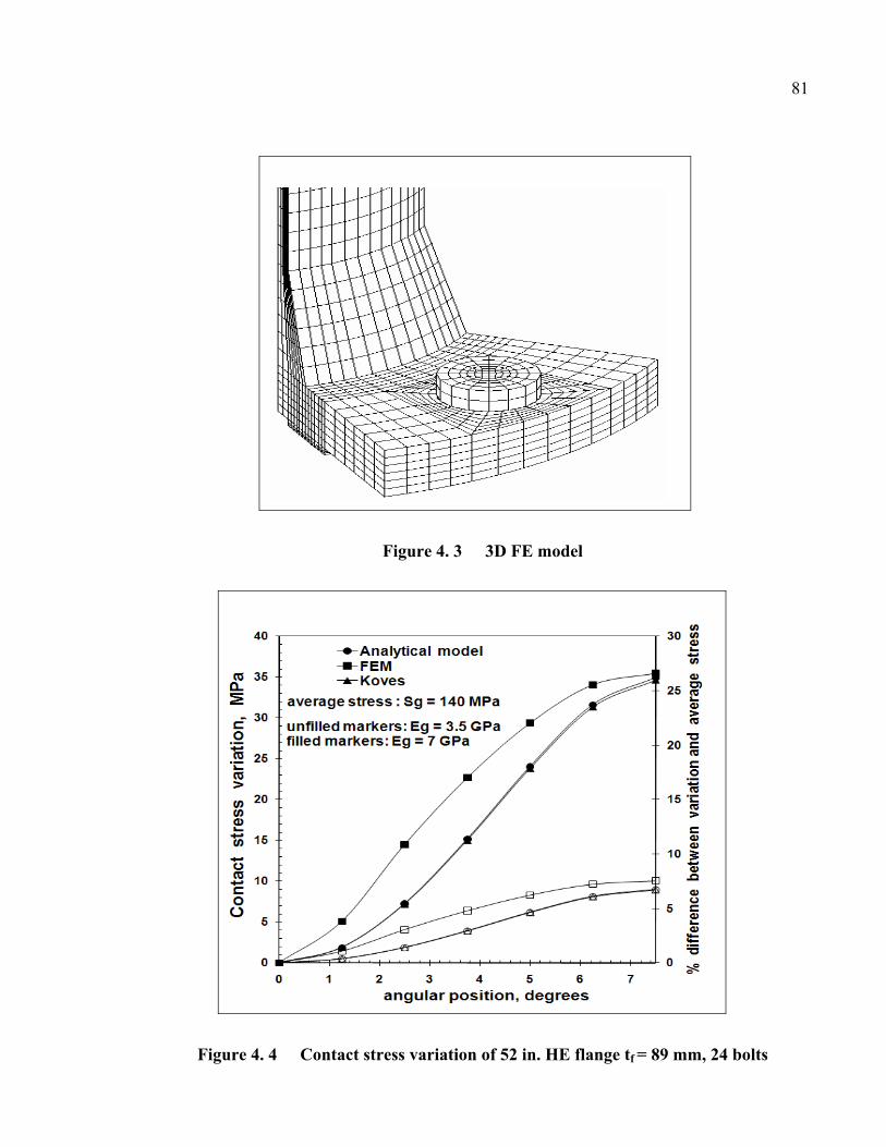
81
Figure 4. 3 3D FE model
Figure 4. 4 Contact stress variation of 52 in. HE flange tf = 89 mm, 24 bolts

82
Figure 4. 5 Contact stress variation of 24 in. HE flange Eg = 2 GPa, 16 bolts
Figure 4.6 Contact stress variation of 24 in. HE flange Eg = 2 GPa

83
Figure 4.7 Contact stress variation of 52 in. HE flange tf = 89 mm
Figure 4.8 Contact stress variation of 52 in. HE flange tf = 143 mm

84
Figure 4.9 Displacement variation of 24 in. HE flange tf = 38 mm
Figure 4.10 Displacement variation of 24 in. HE flange tf = 48 mm

85
Figure 4.11 Displacement variation of 52 in. HE flange tf = 89 mm
Figure 4.12 Displacement variation of 52 in HE flange tf = 143 mm

86
Figure 4.13 Analytical model flange rotation variation of 24 in. HE flange Eg = 3.5 GPa
Figure 4.14 Analytical model flange rotation variation of 24 in. HE flange tf = 38 mm
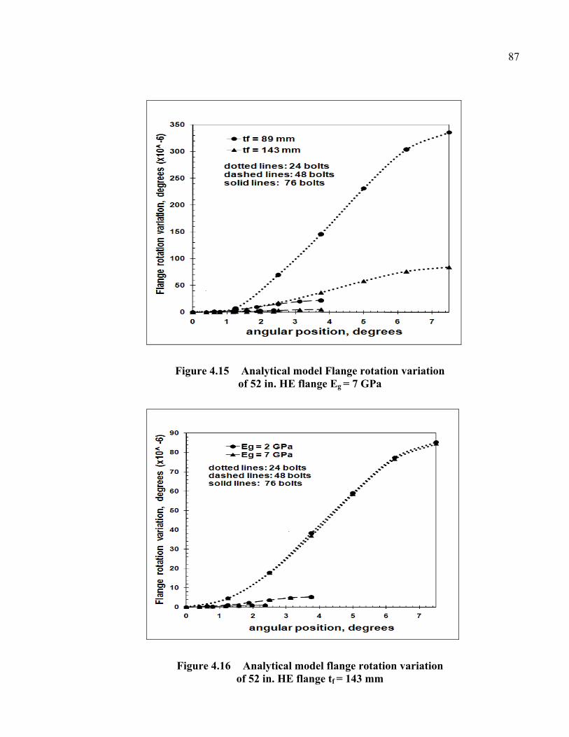
87
Figure 4.15 Analytical model Flange rotation variation of 52 in. HE flange Eg = 7 GPa
Figure 4.16 Analytical model flange rotation variation of 52 in. HE flange tf = 143 mm

88
Figure 4.17 FE radial distribution of contact stress of 52 in. HE flange, tf = 89 mm
Figure 4.18 FE radial distribution of contact stress of 52 in. HE flange, tf = 143 mm

89
Figure 4.19 FE Maximum contact stress variation of 52 in. HE flange, tf = 89 mm
Figure 4.20 FE maximum contact stress variation of 52 in. HE flange, tf = 143 mm
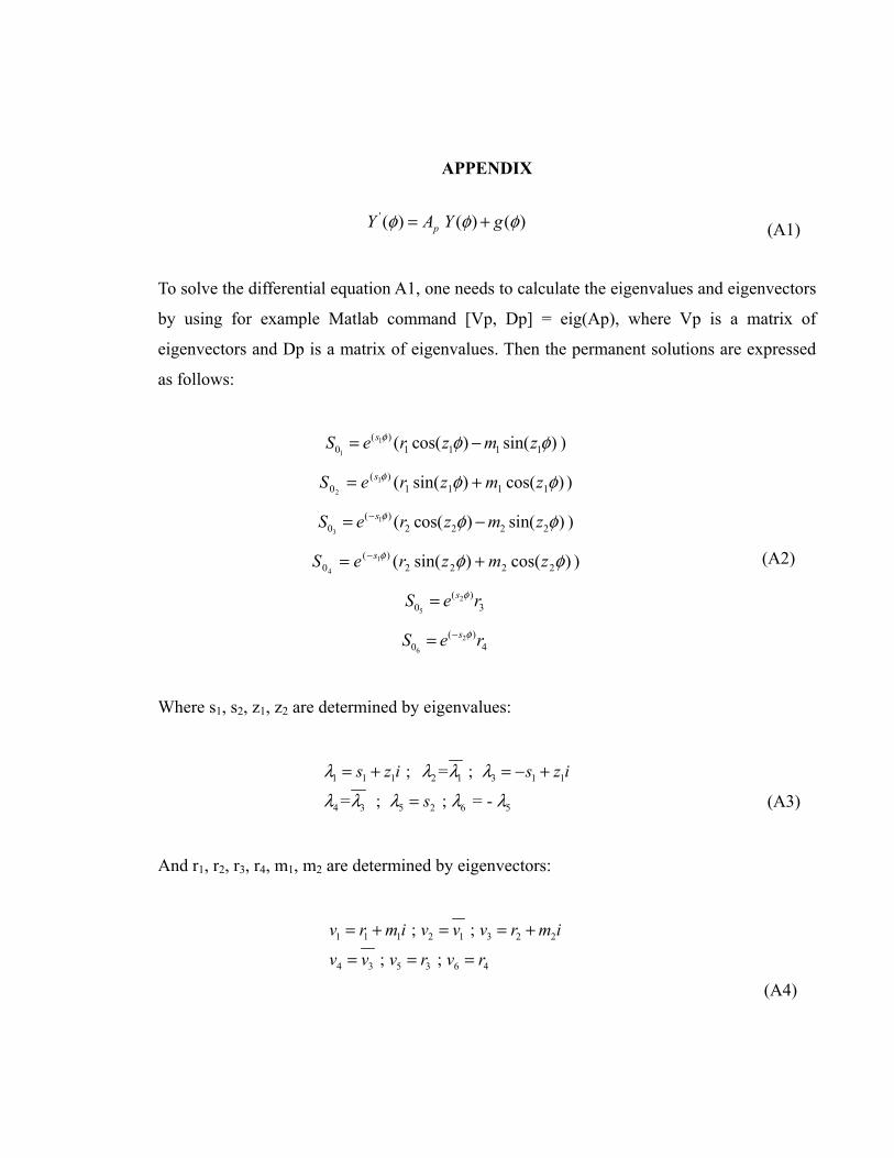
APPENDIX
' ( ) ( ) ( )pY A Y gφ φ φ= +
(A1)
To solve the differential equation A1, one needs to calculate the eigenvalues and eigenvectors
by using for example Matlab command [Vp, Dp] = eig(Ap), where Vp is a matrix of
eigenvectors and Dp is a matrix of eigenvalues. Then the permanent solutions are expressed
as follows:
1
1
( )0 1 1 1 1( cos( ) sin( )sS e r z m zφ φ φ= − )
)cos()sin(( 1111)(
01
2φφφ zmzreS s += )
1
3
( )0 2 2 2 2( cos( ) sin( )sS e r z m zφ φ φ−= − )
)cos()sin(( 2222)(
01
4φφφ zmzreS s += − )
2
5
( )0 3
sS e rφ=
2
6
( )0 4
sS e rφ−=
(A2)
Where s1, s2, z1, z2 are determined by eigenvalues:
1 1 1 2 1 3 1 1
4 3 5 2 6 5
; = ;
= ; ; = -
s z i s z i
s
λ λ λ λλ λ λ λ λ
= + = − +
=
(A3)
And r1, r2, r3, r4, m1, m2 are determined by eigenvectors:
1 1 1 2 1 3 2 2
4 3 5 3 6 4
; ;
; ;
v r m i v v v r m i
v v v r v r
= + = = +
= = =
(A4)

91
Assume that Mp is a fundamental matrix; Mp is satisfied with the following expression:
1 2 3 4 5 60 0 0 0 0 0, , , , ,pM S S S S S S = (A5)
0 at M of evaluation : )0(MM ppp0=φ=
p
0
A x1p pE(x) M M e −= × = : exponential of matrix A
The general solution of the problem gives the following expression [14]:
+φ=φ
φ−−
0
10
1 dt)t(g)t(EY)0(E)(E)(Y (A6)
Where Y0 corresponds with vector Y(ф) at the mid-bolt position (ф=0):
[ ]0 1 2 3 4 5 6; ; ; ; ;Y C C C C C C= (A7)
The boundary conditions are:
1 1( ) ( ) ( ) ( )v v y yα α α α= − = −
2 2( ) ( ) ( ) ( )y yβ α β α α α= − = −
3 3( ) ( ) ( ) ( )y yθ α θ α α α= − = −
' '3 3( ) ( ) ( ) ( )
d d y yds dsθ θα α α α= − = −
' '2 2( ) ( ) ( ) ( )
d d y yds dsβ βα α α α= − = −
, ,5 5( ( ) ( ))n n
b bdM dM P y y P
ds dsα α α α
+ − − = − Δ − − + Δ =
(A8)
Applying the boundary conditions above, Y0 is determined by the expression:

92
1
0 0 p pB Y Ch Y B Ch−
= = (A9)
Where
1 1(1 ,:) (1 ,:)
1 1( 2 ,:) ( 2 ,:)
1 1( 3 ,:) ( 3 ,:)
1 1 1( 6 ,:) ( 6 ,:) ( 2 ,:)
1( 2 ,:)
( ( ) ( 0 ) ) ( ( ) ( 0 ) ) ;
( ( ) ( 0 ) ) ( ( ) ( 0 ) ) ;
( ( ) ( 0 ) ) ( ( ) ( 0 ) ) ;
( ( ) ( 0 ) ) ( ( ) ( 0 ) ) ( ( ) ( 0 ) )
( ( ) ( 0 ) );
f f
p
E E E E
E E E E
E E E E
E E E E E EK G K G R
E EB
R
α α
α α
α α
α α α
α
− −
− −
− −
− − −
−
− −
− −
− −
−− −
− = +
1 1 1( 3 ,:) ( 3 ,:) ( 5 ,:)
1( 5 ,:)
1 1( 6 ,:) ( 6 ,:)
1 1( 4 ,:) ( 4 ,:)
( ( ) ( 0 ) ) ( ( ) ( 0 ) ) ( ( ) ( 0 ) )
( ( ) ( 0 ) );
( ( ) ( 0 ) ) ( ( ) ( 0 ) )
( ( ) ( 0 ) ) ( ( ) ( 0 ) ) ;
f n
f n
E E E E E ER R E I
E EE I
E e p s E E e p s ER R
E e p s E E e p s E
α α α
α
α α
α α
− − −
−
− −
− −
− − − − −
− + −− +
− − + − +
(A10)
and

93
1 1(1,:) (1,:)
0 0
1 1( 2,:) ( 2,:)
0 0
1 1(3,:) (3,:)
0 0
(6,:) 1
( ) ( ) ( ) ( ) ( ) ( ) ( ) ( );
( ) ( ) ( ) ( ) ( ) ( ) ( ) ( );
( ) ( ) ( ) ( ) ( ) ( ) ( ) ( );
( )( ) ( )
f
E E t g t d t E E t g t d t
E E t g t d t E E t g t d t
E E t g t d t E E t g t d t
EE t g t
KG
Ch
α α
α α
α α
α α
α α
α α
α
−− −
−− −
−− −
−
− −
− −
− −
−
=
(6 ,:) 1
0 0
(2,:) (2,:)1 1
0 0
(3,:) (3,:)1 1
0 0
(5,:) (5,:)1
0
( )( ) ( ) ( ) ( )
( ) ( )( ) ( ) ( ) ( ) ( ) ( );
( ) ( )( ) ( ) ( ) ( ) ( ) ( )
( ) ( )( ) ( ) ( )
f
f n f n
Ed t E t g t d t
KG
E EE t g t d t E t g t d t
R RE E
E t g t d t E t g t d tR R
E EE t g t d t
E I E I
α α
α α
α α
α
α
α α
α α
α α
−−
−− −
−− −
−
−
−+ −
−−
−+ −
1
0
1 1( 4,:) (4 ,:)
0 0
(6,:) (6,:)1 1
0 0
( ) ( ) ( );
( ) ( ) ( ) ( ) ( ) ( ) ( ) ( )
( ) ( )( ) ( ) ( ) ( ) ( ) ( );
eps eps
b
eps eps
E t g t d t
P E eps E t g t d t E eps E t g t d t
E eps E epsE t g t d t E t g t d t
R R
α
α α
α α
α α
α α
−−
− − +− −
− + −− −
+ − − − +
− + − + −
(A11)

REFERENCES
[1] ASME Boiler and Pressure Vessel Code, 2001, Section VIII, Division 2, Appendix 2, "Rules for Bolted Flange Connections with Ring Type Gaskets".
[2] EN 1591-1:2001 E, Flanges and their joints – Design rules for gasketed circular flange connections Part 1: Calculation method.
[3] Waters, E, O., Rossheim, D.B., Wesstrom, D.B. and Williams, F.S.G., 1937, “Formulas for Stresses in Bolted Flanged Connections,” transaction of the ASME, 59, pp. 161-169.
[4] Waters, E, O., Rossheim, D.B., Wesstrom, D.B. and Williams, F.S.G., 1949, "Development of General Formulas for Bolted Flanges," Taylor Forge and Pipe Works, Chicago, Illinois.
[5] G&W Taylor-Bonney Division, 1978, “Modern Flange Design”, Bulletin 502, Edition VII, Southfield, Michigan.
[6] George P. B., 1959, “Standards of Tubular Exchanger Manufacturers Association”, TEMA, N.Y. 10017.
[7] Lehnhoff, T. F.; McKay, M. L.; Bellora, V. A., 1992, “Member stiffness and bolt spacing of bolted joints,” American Society of Mechanical Engineers, Pressure Vessels and Piping Division, PVP, v 248, Recent Advances in Structural Mechanics - 1992, p 63-72.
[8] McKee, R., Reddy, H., 1995, “Apparent Stiffness of a Bolted Flange,” American Society of Mechanical Engineers Design Engineering Division, DE-Vol. 83, n 2 Pt 2, Computer Integrated Concurrent Design Conference, pp. 877-883.
[9] Kilborn, D.F., 1975, “Spacing of Bolts in Flanged Joints”. 87 Ser A., n 7, p. 339-342.
[10] Roberts, I., 1950, “Gaskets and Bolted Joints”, Journal of Applied Mechanics, p 169-179.
[11] Koves. W. J., 2007, “Flange Joint Bolt Spacing Requirements”, Proceeding of PVP2007, ASME Pressure Vessel and Piping Division Conference.

95
[12] Volterra et al., 1974, “Advanced Strength of Materials”, Prentice-Hall, INC.,
Engewood Cliffs, N.J., p 379-424.
[13] M’hadheb Mustapha, 2005, “Effet de L’Espacement des Boulons Sur la Distribution des Contraintes Dans Un Assemblage À Brides Boulonnées Muni d’un Joint d’Étanchéité,” Master thesis, Ecole de Technologie Superieure.
[14] Martin Braun, 1983, “Differential Equations and Their Applications” Sringer-Verlag, Third Edition, USA.
[15] ANSYS, 2004, ANSYS Structural Analysis Guide, Version 9.
[16] Nechache A. and Bouzid A., 2007, "Creep Analysis of Bolted Flange Joints," International Journal of Pressure Vessel and Piping, Vol. 84, n. 3, p. 185-194.
[17] Bouzid, A. H., and Champliaud, H., 2004, “Contact Stress Evaluation of Nonlinear Gaskets Using Dual Kriging Interpolation”, Journal of Pressure Vessel Technology, v 126, No 4, p 445- 450.

CHAPTER 5
PAPER 2: ON THE USE OF THEORY OF RINGS ON NON-LINEAR ELASTIC FOUNDATION TO STUDY THE EFFECT OF BOLT SPACING
IN BOLTED FLANGE JOINTS
Tan Dan Do1, Abdel-Hakim Bouzid2, Thien-My Dao3 1 Ph. D. student, Mechanical Engineering Department, École de technologie supérieure, 1100
Notre-Dame St. West, Montreal, Quebec, H3C 1K3 email: [email protected]
2 ASME Fellow, Professor, Mechanical Engineering Department, École de technologie
supérieure, 1100 Notre-Dame St. West, Montreal, Quebec, H3C 1K3 email: [email protected]
3 Professor, Mechanical Engineering Department, École de technologie supérieure, 1100
Notre-Dame St. West, Montreal, Quebec, H3C 1K3 email: [email protected]
Presented at 2010 ASME – PVP Conference, Bellevue, Washington, July, 2010, Paper No
PVP2010-26001
Was ranked as one of the Finalist Papers of the Conference
Was awarded as the Winner of the Student Paper Competition, Ph. D. category
Accepted by the Journal of Pressure Vessel Technology, June, 2011

97
Abstract
Bolted flange joints are extensively used to connect pressure vessels and piping equipment
together. They are simple structures that offer the possibility of disassembly. However, they
often experience leakage problems due to a loss of tightness as a result of a non-uniform
distribution of gasket contact stresses in the radial and circumferential direction. Many
factors contribute to such a failure; the flange and gasket stiffness and bolt spacing design
combination being one of them.
In our recent paper the effects of bolt spacing was investigated based on the theory of circular
beams resting on a linear elastic foundation [1]. This paper is an extension of the work in
which an analytical solution based on the true gasket non-linear behavior is developed. The
study focuses on the distribution of the gasket contact stress of two large diameter flanges
namely a 52 and a 120 in heat exchanger flanges. The non-linear gasket behavior solution is
compared to the FEA and the linear gasket behavior solution for evaluation and validation.
Keywords: tightness, gasket contact stresses, bolt spacing, circular beam
Résumé
L’assemblage de brides boulonnées est largement utilisé pour connecter divers appareils à
pression avec d’autres équipements de tuyauterie. Les brides boulonnées sont des structures
simples pouvant être démontées. Elles présentent souvent, malheureusement, des problèmes
de fuites dus à une perte d’étanchéité suite à une distribution non-uniforme du joint de
contact dans la direction radiale et circonférentielle. Plusieurs facteurs contribuent à cet
échec dont la combinaison bride, joint de rigidité et conception du joint d’espacement.
Récemment, nous publions un papier dans lequel nous étudions l’effet de l’espacement entre
les boulons basé sur la théorie des faisceaux circulaires qui, elle-même, repose sur une
fondation élastique linéaire [1]. Ce second papier est une extension du premier dans lequel

98
une solution analytique basée sur le véritable comportement non-linéaire du joint est
développée. L’étude met l’emphase sur la distribution de la contrainte du joint de contact de
deux brides de grand diamètre (52 pouces) et d’un échangeur de chaleur de 120 pouces. La
solution non-linéaire obtenue du comportement du joint est comparée au "FEA" et à la
solution à comportement linéaire.
Mots-clés : étanchéité, contrainte du joint de contact, espacement des boulons, faisceau
circulaire
Nomenclature
β bending rotation (rad)
θ flange twist rotation (rad)
A flange outside diameter (mm)
b flange width equals to (A-B)/2 (mm)
B flange inside diameter (mm)
C bolt circle (mm)
D0 diameter of flange centroïd (mm)
d, db nominal bolt diameter (mm)
Ef Young’s modulus of flange (MPa)
Eg Young’s modulus of gasket (MPa)
Fb total bolt force (N)
Ff foundation reaction force (N/mm)
Fn axial force per unit length (N/mm)
g0,g1 hub small and big end thickness (mm)
h hub length (mm)
G gasket reaction diameter (mm)
Gf shear modulus (MPa)
J torsional moment of area (MPa)
K1, K2 elastic foundation constant (MPa)
Mb ring bending moment (N.mm)

99
Mf flange twisting moment (N.mm/mm)
M0 discontinuity edge moment (N.mm/mm)
Mn ring bending moment (N.mm)
Mt ring twist moment (N.mm)
nb bolt number
N gasket width (mm)
Nt ring axial force (N)
Pb ring axial force per unit length (N/mm)
qb ring twisting moment per unit length (N.mm/mm)
qn ring bending moment per unit length (N.mm/mm)
R radius of flange centroïd equal to D0/2 (mm)
tf flange thickness(mm)
u axial flange displacement (mm)
Vb ring axial shear force (N)
Vn ring radial shear force (N)
x longitudinal distance (mm)
y axial distance from flange centroïd (mm)
yi variables
Acronyms
ASME
HE
American Society of Mechanical Engineers
Heat Exchanger

100
5.1 Introduction
Bolted flange joints are part of pressure vessels and piping equipment that need careful
design considerations. With the need for more onerous service duties, as seen typically in the
oil and gas exploration industries, there is an increasing demand for higher operational
pressures and temperatures as the industry seeks greater efficiency. However bolted joint
remains the week link between pressurized equipments as they are prone to leakage. Their
non-desirable leakage behavior generates costs due to maintenance, loss of revenue, and
sometimes penalties for non-compliance with environmental laws.
Presently, great effort is being made worldwide to reduce leakage to minimum acceptable
levels, by introducing new tightness-based design procedures for bolted flange joints in order
to obtain proper bolted flange joint connections, ensuring both joint structural integrity and
joint leak tightness. Even though considerable research has already been undertaken
worldwide, emphasizing structural integrity, flange joint components are still designed based
on experience. Because the current ASME flange design procedure [2] is not based on
leakage, there is no consensus within the ASME code committee to adopt a more realistic and
modern flange design procedure such as the European EN1591 standard [3].
Experiments show that the leak rates of bolted flange joints are depend not only on the
average contact stress, but also on the way the stress is distributed across the gasket width.
The radial and circumferential stress distribution depends not only on the flange thickness,
the flange rotation and bolt spacing but also on the gasket no-linear stiffness. The theory of a
circular beam supported on a linear elastic foundation has been the subject of numerous
investigations involving bolted flange joints [1,4]. Since the behavior of a gasket is complex,
several idealized models have been introduced [5,6]. The simplest approach was to assume
that the gasket stiffness is a constant, with results of the bending foundation stiffness being
constant as well. However, the impact of the above parameters with a nonlinear gasket
behavior is not known and further investigation is necessary.

101
Since the early work of Water et al. [7,8] on bolted joints in the late thirties, there has been
little research on the effects of bolt spacing on the circumferential distribution of the gasket
contact stress and the leakage tightness of bolted flange connections. Taylor Forge [9] has
developed a rule on bolt spacing which was adopted by TEMA [10], but not ASME [2].Other
approaches have been applied for joints with metal-to-metal contact [11,12]. Roberts [13]
developed a numerical summation approach to achieve maximum bolt spacing by
considering the flange to be behaving as a straight beam on an elastic foundation. In 1975,
Kilborn et al. [14] carried out a study on the spacing of bolts in flanged joints. In 2007,
Koves [4] expanded the approach used by Roberts, which was based on beam on an elastic
foundation, to develop a closed form analytical solution not requiring a numerical
summation. Bouzid et al. [5, 15] concentrated on flange rotation and the creep analysis of
bolted flange joints, and presented Dual Kriging Interpolation to evaluate the contact stress of
a non-linear gasket.
This paper presents an approach based on the extension of the circular beam theory to which
the non-linear elastic behavior of the foundation was incorporated. The analytical solution
provides an evaluation of the circumferential distribution of the gasket contact stress based
on flange deformation and the gasket nonlinear stiffness. The local deformation of the flange
and bolt spacing are few parameters to consider as they may have an influence on the contact
stress. To validate the analytical model, three-dimensional nonlinear finite element analysis
using a general purpose finite element computer program was used to simulate the three-
dimensional behavior of the bolted flange joints.
5.2 Analytical model
Half of the bolted flange joint shown in Fig.5.1 is modeled by a simple circular ring that rests
on a non-linear elastic foundation. The three bending and twisting moments and the three
forces generated by the initial tightening are considered. The analytical development is
similar to the one of the theory of a circular beam on an elastic foundation [16].

102
In the case of the initial bolt-up, the flange moment per unit circumference Mf is obtained by
the expression:
0 2π− =
b
fF C GMD
(5.1)
Consider an element of the flange ring assumed as a circular beam supported by the gasket
considered as the non linear elastic foundation, with the two cross-sections infinitely close to
each other at a distance ds, with the rotation centers, Gr and Gr’, subjected to the loading
shown in Fig. 5.2. The reaction of the gasket is supposed to be nonlinear of the form:
(5.2)
The equilibrium of forces in the 3 directions reduces to:
(5.3)
The equilibrium of moments about the 3 axes reduces to:
2
(5.4)
As in beam theory the slope can be expressed as the derivative of the displacement then:

103
(5.5)
Therefore:
n f ndM E I
R dsθ β = −
β θ = +
t fdM G J
R ds
(5.6)
Substituting Eqs.(5.6) into (5.3) and (5.4) , noting that qn = 0 , qb = Mf and Pb = Fb/2πC and
assuming that y1 = ν (flange displacement); y2 = β (bending rotation); y3 = θ (twist rotation);
y4 = Vb (shear force); y5 = Mn (bending moment) ; y6 = Mt (twist moment); the following
expressions must be satisfied:
'1 2y y β= =
' 3 52
n
f n f n
y y MyR E I R E I
θ= − = −
' 6 t23
f f
y Myy
G J R G J R
β= − = −
( )' 24 1 1 2 1
0b
Gy K y K y PD
= + −
' 65 4
tb
y My y VR R
=− + =− +
( )' 25 06 1 1 2 1
0
( )
2fy D G Gy M K y K yR D
−= + + +
(5.7)
The above differential equation system which governs a circular beam on elastic foundation
[17] may be written in the matrix form as follows:

104
yyyyyy A
yyyyyy 000P0M
(5.8)
Noting that matrix A is not constant and depends on y1 therefore the system of equations
above is non linear and requires the use of non linear methods to resolve the problem. Matlab
[18] software, supported by the functions ODE45 based on Runge Kutta method, was used to
solve the above system of equations.
Where
A0 1 0 0 0 00 0 1R 0 1E I 00 1R 0 0 0 1G JK y K GD 0 0 0 0 00 0 0 1 0 1RK y K D G G2D 0 0 0 1R 0
5.9
5.3 Flange working examples
Matlab software [18] was used to solve the above system of equations. Two bolted flange
joints used in pairs were studied; one is 52 in HE channel flange and the other is a 120 in HE
flange. Based on the analytical solution as described above, flange displacements and gasket
contact stresses were calculated at the position of gasket reaction diameter G. The initial bolt-
up load was 276 MPa. The Young modulus of flange and bolts are assumed as 207 MPa. The

105
corrugated metal sheet (CMS) gasket experimental data was applied both for the analytical
solutions and the FEM. The dimensions of the two flanges are shown in Table 5.1.
5.4 Finite element model
To validate the analytical model, two 3-dimensional numerical FEM models (Fig. 3) of the
two bolted joints described in Table 5.1 above were built and run on ANSYS [19]. Because
of the symmetry with the plane passing through the gasket mid thickness and the bolts as
well as the repeated loads equally spaced around the circumference, it is only possible to
model an angular portion that passes through two longitudinal planes located at two adjacent
bolts. A uniform simultaneous load is applied to all bolts by imposing an equivalent axial
displacement to the bolt mid-plane nodes to produce the target initial bolt-up stress.
5.5 Results and discussion
Figure 5.4 shows the FEM variation of the gasket displacement in the circumferential
direction of the 52 in HE flange with 32 bolts. Due to flange rotation the displacement is
shown at three gasket radial locations with the maximum, and minimum being at the gasket
outside and inside diameters respectively. This data is useful to verify gasket lift off and
crushing.
The displacement variations at the gasket reaction diameter are of interest for comparison
with the analytical solution. Due to the symmetry, the distribution is only given for half of the
sector delimited between two adjacent bolts. The analytical and FE distributions are shown
for three different flange thicknesses, namely 50.8 mm, 88.9 mm and 142.8 mm. Figures 5.5
to 5.7 treated four different bolt numbers, namely 32, 48, 60 and 76 in order to depict the
effect.
Similarly the gasket displacement variation results for the 120 in HE flange with three
different flange thicknesses, namely, 74.6, 114.3 165.1 mm and three different bolt numbers

106
namely 56, 68 and 84 bolts can be found in Figs. 5.8 to 5.11. It can be said that the maximum
gasket displacement variation is located exactly between bolts and increases with a decrease
of flange thickness and number of bolts. It is to be noted that the displacements of the linear
and nonlinear analytical solutions compare well with those of FEA.
Figure 5.12 shows the distribution of the gasket contact stress variation around the
circumference at the gasket reaction location for the 52 in HE flange as given by the linear,
non linear and FEM solutions. The minimum and maximum distributions at the inside and
outside diameter of the gasket are also included for comparison and illustration of the flange
rotation effect. The comparison between the three methods is well appreciated in Figs. 5.13
to 5.15. The effect of bolt spacing is clearly shows in each figure as the exercise was
conducted for different number of bolts. While the nonlinear solution results match pretty
well with the FE ones the linear solution predicts lower contact stress variation between any
two bolts and therefore cannot depict the real flange-gasket interaction behavior as it
underestimates the effect. This is particularly true when the number of bolts or the flange
if increased. This was the subject of our previous paper [1].
For the 52 in HE flange, the difference in the gasket contact stress variations with respect to
the average value is 0.45% for a flange thickness of 142.9 mm, and 10% for a flange
thickness of 50.8 mm. For the 120 in HE flange, it is 0.1% for a flange thickness of 165.1
mm and 9% for a flange thickness of 74.6 mm. Both cases are obtained with the lower
number stiffness is relatively small.
Again the same observations could be made with the 120 in HE flange. As shown in Fig.
5.16, the analytical solution is outside the range of the FE minimum and maximum while the
non linear solution lies in between. Once again the non-linear solution results compare quite
well with those of FE method. Figures 5.17 to 5.19 show the comparison of the gasket
contact stress variations at the gasket reaction for different number of bolts and flange
thickness.

107
It can be seen from these figures that a decrease in the number of bolts or flange stiffness will
increase the gasket contact stress variations between any two bolts. A third parameter not
considered in this paper worth mentioning is the gasket stiffness which increase the stress
variation of bolts.
Figure 5.20 and 5.21 show the effect of bolt spacing on the maximum contact stress
variations for different flange thickness. For the 52 in HE flange, the maximum contact stress
variation is practically not effected by bolt spacing when flange thickness is larger than 110
mm. The same conclusion was found for the 120 in HE flange when flange thickness is larger
than 135 mm.
5.6 Conclusion
This study proposes an analytical approach to looking at the effect of bolt spacing and its
impact on in-service maintenance. The proposed analytical model is based on the theory of a
circular beam on a non-linear elastic foundation. It was tested on two different bolted joint
sizes, with a variation of the flange thickness and bolt number. The non-linear analytical
results are in good agreement with the FEM results as compared to the analytical model
results. The developed model is based on non-linear elastic foundation behavior defined by a
second order curve fitting of CMS gasket load compression data. While flange rotation
affects the radial distribution of gasket stress, the number bolt and flange thickness have a
significant effect of the circumferential distribution of the contact stress. This model could
potentially be used to improve bolt spacing designs and give guidance to achieve safe in-
service bolt replacement and hot retorque.

APPENDIX
Table 5. 1 Nominal flange dimensions of 52 in. and 120 in. HE flange
Flange size
(in)
A
in
(mm)
B
in
(mm)
C
in
(mm)
g0
in
(mm)
g1
in
(mm)
h
in
(mm)
52 in 58⅜
(1483)
51
(1295)
56¼
(1429)
⅝
(16)
1⅛
(29)
1¼
(32)
120 in 127
(3226)
120¼
(3055)
124½
(3162)
⅝
(16)
1⅛
(29)
3⅛
(32)
Flange size
(in)
tf
in
(mm)
nb db
in
(mm)
Ag
in
(mm)
N
in
(mm)
52 in 2(50.8)
3½ (88.9)
5⅝(142.9)
5⅝(142.9)
76
60
48
32
1(25.4)
1¼(32)
1½(38)
1½(38)
53⅛
(1349)
½
(12.7)
120 in 3(74.6)
4½(114.3)
6½(165.1)
84
68
56
1(25.4)
1¼(32)
1½(38)
123
(3124)
½
(12.7)

109
Figure 5. 1 Bolted flange joint
Figure 5. 2 Infinitesimal element model of flange

110
Figure 5. 3 3D FE model
Figure 5. 4 FEA Gasket displacement variations of 52 in HE flange, 32 bolts

111
Figure 5. 5 Gasket displacement variations of 52 in HE flange, tf = 88.9 mm
Figure 5. 6 Gasket displacement variations of 52 in HE flange, tf =142.9 mm
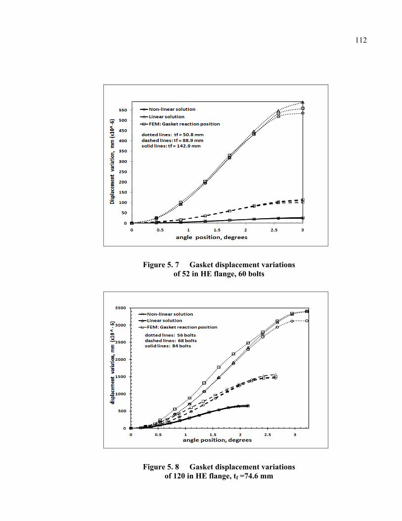
112
Figure 5. 7 Gasket displacement variations of 52 in HE flange, 60 bolts
Figure 5. 8 Gasket displacement variations of 120 in HE flange, tf =74.6 mm
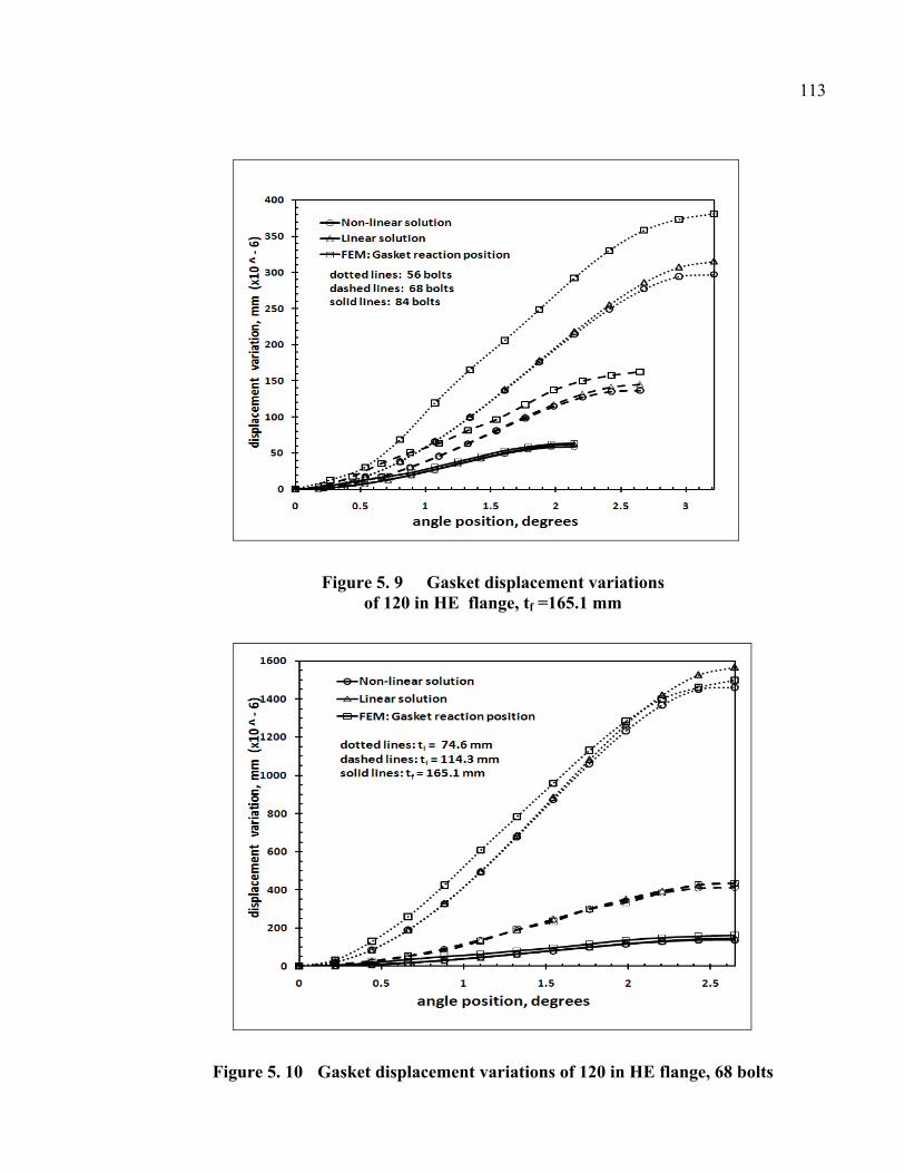
113
Figure 5. 9 Gasket displacement variations of 120 in HE flange, tf =165.1 mm
Figure 5. 10 Gasket displacement variations of 120 in HE flange, 68 bolts

114
Figure 5. 11 Gasket displacement variations of 120 in HE flange, 84 bolts
Figure 5. 12 Contact stress variations of 52 in HE flange 32 bolts, tf =88.9 mm

115
Figure 5. 13 Contact stress variations of 52 in HE flange, tf =50.8 mm
Figure 5. 14 Contact stress variations of 52 in HE flange, tf =142.9 mm

116
Figure 5. 15 Contact stress variations of 52 in HE flange, 32 bolts
Figure 5. 16 Contact stress variations of 120 in HE flange tf =74.6 mm, 56 bolts

117
Figure 5. 17 Contact stress variations of 120 in HE flange, tf =165.1 mm
Figure 5. 18 Contact stress variations of 120 in HE flange, 56 bolts

118
Figure 5. 19 Contact stress variations of 120 in HE flange, 68 bolts
Figure 5. 20 Maximum contact stress variations vs flange thickness of 52 in HE flange
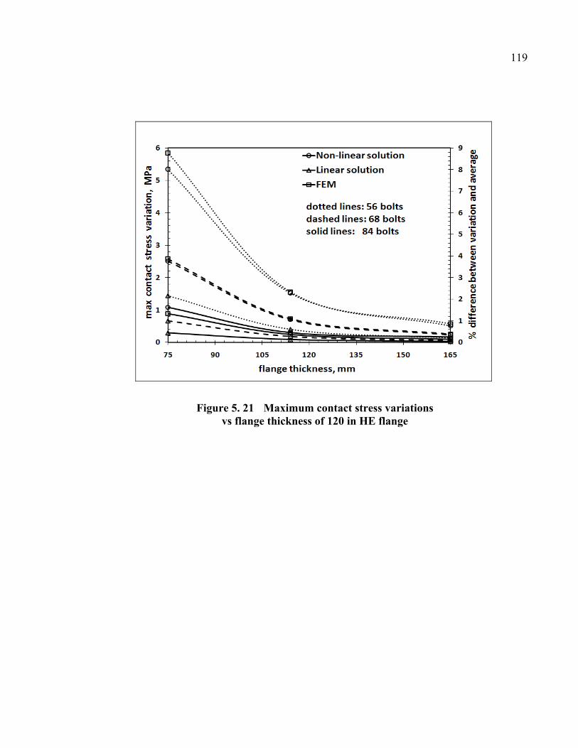
119
Figure 5. 21 Maximum contact stress variations vs flange thickness of 120 in HE flange

REFERENCES
[1] Tan Dan DO, Bouzid. A. H., Thien-My Dao, 2010, “Effect of Bolt Spacing on the Circumferential Distribution of Gasket Contact Stress in Bolted Flange Joints,” Submitted to the Journal of Pressure Vessel Technology.
[2] ASME Boiler and Pressure Vessel Code, 2001, Section VIII, Division 2, Appendix 2, Rules for Bolted Flange Connections with Ring Type Gaskets.
[3] EN 1591-1:2001 E, Flanges and their joints – Design rules for gasketed circular flange connections Part 1: Calculation method.
[4] Koves. W. J., 2007, “Flange Joint Bolt Spacing Requirements,” Proceedings of 2007 ASME Pressure Vessel and Piping Division Conference, PVP Vol. 3, p 3-10.
[5] Bouzid, A. H., and Champliaud, H., 2004, “Contact Stress Evaluation of Nonlinear Gaskets Using Dual Kriging Interpolation,” Journal of Pressure Vessel Technology, Vol. 126, no 4, pp. 445- 450.
[6] M’hadheb Mustapha, 2005, Effet de L’Espacement des Boulons Sur la Distribution des Contraintes Dans Un Assemblage À Brides Boulonnées Muni d’un Joint d’Étanchéité, Master thesis, École de technologie supérieure.
[7] Waters, E, O., Rossheim, D.B., Wesstrom, D.B. and Williams, F.S.G., 1937, “Formulas for Stresses in Bolted Flanged Connections,” Transactions of the ASME, 59, pp. 161-169.
[8] Waters, E, O., Rossheim, D.B., Wesstrom, D.B. and Williams, F.S.G., 1949, Development of General Formulas for Bolted Flanges, Taylor Forge and Pipe Works, Chicago, Illinois.
[9] G&W Taylor-Bonney Division, 1978, “Modern Flange Design”, Bulletin 502, Edition VII, Southfield, Michigan.
[10] George P. B., 1959, Standards of Tubular Exchanger Manufacturers Association, TEMA, N.Y. 10017.
121
[11] Lehnhoff, T. F.; McKay, M. L.; Bellora, V. A., 1992, “Member stiffness and bolt spacing of bolted joints,” American Society of Mechanical Engineers, Pressure Vessels and Piping Division, PVP, v 248, Recent Advances in Structural Mechanics - 1992, pp. 63-72.
[12] McKee, R., Reddy, H., 1995, “Apparent Stiffness of a Bolted Flange,” American Society of Mechanical Engineers Design Engineering Division, DE-Vol. 83, no 2 Pt 2, Computer Integrated Concurrent Design Conference, pp. 877-883.
[13] Roberts, I., 1950, “Gaskets and Bolted Joints,” Journal of Applied Mechanics, pp.169-179.
[14] Kilborn, D.F., 1975, “Spacing of Bolts in Flanged Joints,” 87 Ser A., no 7, pp. 339-342.
[15] Nechache A. and Bouzid A., 2007, “Creep Analysis of Bolted Flange Joints,” International Journal of Pressure Vessel and Piping, Vol. 84, no 3, pp. 185-194.
[16] Volterra et al., 1974, Advanced Strength of Materials, Prentice-Hall, INC.,
Engewood Cliffs, N.J., pp. 379-424.
[17] Martin Braun, 1983, Differential Equations and Their Applications, Sringer-Verlag, Third Edition, USA.
[18] Matlab, 2005, version 7.0.4.365, Release 14.
[19] ANSYS, 2007, ANSYS Academic Teaching Advanced, Version 11.

CHAPTER 6
PAPER 3: A SIMPLIFIED METHOD FOR ESTIMATING BOLT SPACING IN BOLTED FLANGE JOINTS
Tan Dan Do1, Abdel-Hakim Bouzid2, Thien-My Dao3
1 Ph. D. student, Mechanical Engineering Department, École de
technologie supérieure, 1100 Notre-Dame St. West, Montreal, Quebec, H3C 1K3 email: [email protected]
2 ASME Fellow, Professor, Mechanical Engineering Department, École de
technologie supérieure, 1100 Notre-Dame St. West, Montreal, Quebec, H3C 1K3 email: [email protected]
3 Professor, Mechanical Engineering Department, École de
technologie supérieure, 1100 Notre-Dame St. West, Montreal, Quebec, H3C 1K3 email: [email protected]
Submitted to the ASME 2012 Pressure Vessels & Piping Division Conference,
PVP2012, July 15-19, 2012, Toronto, Ontario, Canada.
Submitted to the International Journal of Pressure Vessel and Piping, October 2011.
Abstract
Bolted flange joints are extensively used to connect pressure vessels and piping equipment
together. They are simple structures that offer the possibility of disassembly. However, they
often experience leakage problems due to a loss of tightness as a result of a non-uniform
distribution of gasket contact stresses in the radial and circumferential direction. Many
factors contribute to such a failure; the flange and gasket stiffness and bolt spacing design
combinations being a couple of them.
In our recent papers the effects of bolt spacing was investigated based on the theory of
circular beams resting on a linear elastic foundation and based on the theory of ring on non-
linear elastic foundation. The variations of the contact stress between bolts were of a concern.

123
This paper is an extension of the work in which an analytical solution based on the theory of
circular beams resting on a linear elastic foundation has been developed to determine flange
bolt spacing. . The relationship between bolt spacing, gasket compression modulus and
flange thickness is deduced from an analysis that considers a maximum tolerated gasket
contact stress difference between any two bolts.
Keywords: leakage, tightness, bolt spacing, linear regression model
Résumé
Les assemblages à brides boulonnées sont largement utilisés pour connecter ensemble des
appareils sous pression à des équipements de tuyauterie. Ce sont des structures simples qui
sont aisées à démonter. Cependant, ils ont fréquemment des problèmes de fuite dus à une
perte d'étanchéité à la suite d'une distribution non uniforme des contraintes radiales et
circonférentielles au niveau du joint. Plusieurs facteurs peuvent causer une telle défaillance.
Entre autre, on peut citer pour cause de fuite, la rigidité de la bride et du joint et l’espacement
des boulons inadéquats.
Dans nos récents articles, les effets de l'espacement des boulons a été étudié sur la base de la
théorie des poutres circulaires reposant sur une fondation élastique linéaire et la théorie de
l'anneau reposant sur une fondation élastique non- linéaire. Nous nous étions focalisés sur la
variation de la contrainte de compression entre les boulons. Cet article est la suite de nos
travaux au cours desquels une solution analytique basée sur la théorie des poutres circulaires
reposant sur une fondation élastique linéaire a été développé pour déterminer l'espacement
des boulons de bride. La relation entre l'espacement des boulons, le module de compression
du joint et l’épaisseur de la bride est déduite d'une analyse qui prend en considération un
intervalle de tolérance maximal de la contrainte de compression entre deux boulons.
Mots-clés: fuites, étanchéité, espacement des boulons, modèle de régression linéaire
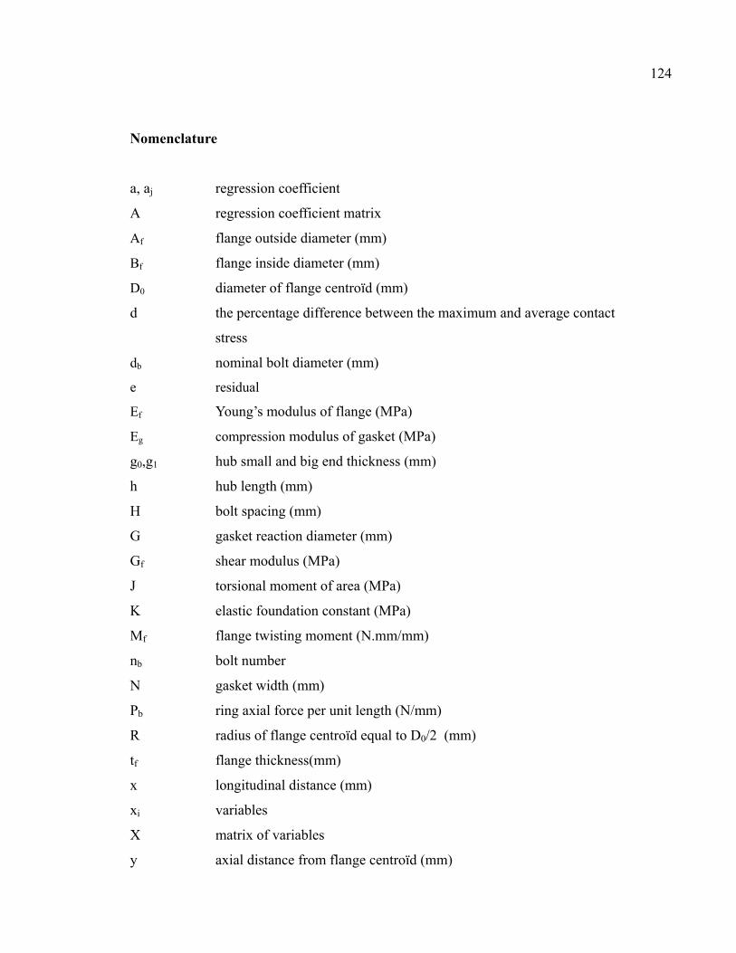
124
Nomenclature
a, aj regression coefficient
A regression coefficient matrix
Af flange outside diameter (mm)
Bf flange inside diameter (mm)
D0 diameter of flange centroïd (mm)
d the percentage difference between the maximum and average contact
stress
db nominal bolt diameter (mm)
e residual
Ef Young’s modulus of flange (MPa)
Eg compression modulus of gasket (MPa)
g0,g1 hub small and big end thickness (mm)
h hub length (mm)
H bolt spacing (mm)
G gasket reaction diameter (mm)
Gf shear modulus (MPa)
J torsional moment of area (MPa)
K elastic foundation constant (MPa)
Mf flange twisting moment (N.mm/mm)
nb bolt number
N gasket width (mm)
Pb ring axial force per unit length (N/mm)
R radius of flange centroïd equal to D0/2 (mm)
tf flange thickness(mm)
x longitudinal distance (mm)
xi variables
X matrix of variables
y axial distance from flange centroïd (mm)

125
yi variables
error
Acronyms
ASME American Society of Mechanical Engineers
CMS Corrugated Metal Sheet
HE Heat Exchanger
6.1 Introduction
Flange designs have been the subject of a lot of criticism as they do not provide an accurate
method for the determination of appropriate bolt spacing. Even though considerable research
has already been undertaken worldwide on both structural integrity and leakage tightness,
flange joint components are still designed based on experience. Because the current ASME
flange design procedure [1] is not based on leakage, there is no consensus within the ASME
code committee to adopt a more realistic and modern flange design procedure such as that of
the European EN1591 standard [2]. Since the early work of Water et al. [3,4] in the late
thirties, there has been little research on the effect of bolt spacing on the circumferential
distribution of the gasket contact stress and the leakage tightness of bolted flange
connections. Taylor-Bonney Division [5] has developed a rule on bolt spacing which was
adopted by TEMA [6] but not ASME [1]. The maximum spacing between bolt centers when
exceeding 2d t is determined by the expression:
H 2 d 6tm 0.5 6.1
The theory of a circular beam supported on a linear elastic foundation has been the subject of
few investigations involving bolted flange joints [7]. Since the mechanical behavior of a
gasket is complex, idealized models have been introduced [8]. The simplest approach was to
assume that the gasket has a linear elastic behavior making the foundation stiffness constant.
126
Other approaches have been applied for joints with metal-to-metal contact [9,10]. Roberts
[11] developed a numerical summation approach to achieve maximum bolt spacing by
considering the flange to behave as a straight beam on an elastic foundation. In 1975, Kilborn
[12] tackled the subject of bolt spacing in flanged joints without suggesting an analytical
solution. In 2007, Koves [13] expanded the approach used by Roberts based on the theory of
beams on elastic foundation, to develop a closed form analytical solution not requiring a
numerical summation. Bouzid et al. [14] concentrated on the effect of flange rotation on
tightness, and presented Dual Kriging Interpolation to evaluate the radial distribution of
contact stress of a non-linear gasket. A circumferential distribution of the gasket contact
stress is a key parameter to estimate the leakage performance of bolted flange joints.
This paper presents a method to estimate bolt spacing based on the extension of the circular
beam theory to which the linear elastic behavior of the foundation was incorporated. The
analytical solution provides an evaluation of the bolt spacing based on the maximum
difference in the gasket contact stress in the circumferential direction as a function of the
joint and the gasket stiffness. To realize the analytical model for application, the linear
regression model will be developed in order to have the same formula for five sizes of the
bolted flange joints.
6.2 Analytical model
Half of the bolted flange joint is modeled by a simple circular beam that rests on a linear
elastic foundation. The analytical development is similar to the one used in [15]. Considering
an element of the flange assumed as a circular beam supported by the gasket acting as the
elastic foundation, the three bending and twisting moments and the three forces generated by
the initial tightening are considered. The equilibrium of forces and moments in the 3
directions of an infinitesimal element model of flange reduces to the system of differential
equations and may be written in the matrix form as follows [16-19]:
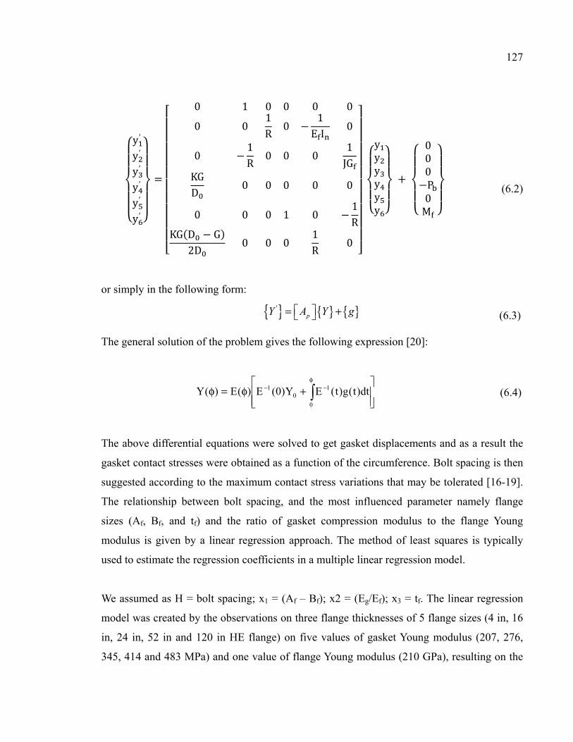
127
y′y′y′y′y′y′
0 1 0 0 0 00 0 1R 0 1E I 00 1R 0 0 0 1JGKGD 0 0 0 0 00 0 0 1 0 1RKG D G2D 0 0 0 1R 0
yyyyyy 000P0M
(6.2)
or simply in the following form:
'pY A Y g = + (6.3)
The general solution of the problem gives the following expression [20]:
+φ=φ
φ−−
0
10
1 dt)t(g)t(EY)0(E)(E)(Y
(6.4)
The above differential equations were solved to get gasket displacements and as a result the
gasket contact stresses were obtained as a function of the circumference. Bolt spacing is then
suggested according to the maximum contact stress variations that may be tolerated [16-19].
The relationship between bolt spacing, and the most influenced parameter namely flange
sizes (Af, Bf, and tf) and the ratio of gasket compression modulus to the flange Young
modulus is given by a linear regression approach. The method of least squares is typically
used to estimate the regression coefficients in a multiple linear regression model.
We assumed as H = bolt spacing; x1 = (Af – Bf); x2 = (Eg/Ef); x3 = tf. The linear regression
model was created by the observations on three flange thicknesses of 5 flange sizes (4 in, 16
in, 24 in, 52 in and 120 in HE flange) on five values of gasket Young modulus (207, 276,
345, 414 and 483 MPa) and one value of flange Young modulus (210 GPa), resulting on the

128
number of observations on a model is 75. The linear regression model equation used to
describe this relationship is [21]:
H a a A B a EE a t H a a A B a EE a t (6.5) H a ∑ a x i 1,2, … ,75
Where aj is a regression coefficient and is the error.
The above equation may be written in matrix notation as:
H X A (6.6)
Where
H HH...H
, X 1 A B E /E t 1 A B E /E t . . . .. . . .. . . .1 A B E /E t
,
(6.7)
A aaaa , and ...
The least squares estimator of A is: A X X X H (6.8)
or: X X A X H
or in the scalar form:

129
75 ∑ A B ∑ EE ∑ t ∑ A B ∑ A B ∑ A B EE ∑ A B t ∑ EE ∑ EE A B ∑ EE ∑ EE t ∑ t ∑ t A B ∑ t EE ∑ t
aaaa ∑ H∑ A B H∑ EE H∑ t H
(6.9)
The fitted regression model is: H X A (6.10)
In scalar notation, the fitted regression model is:
H a ∑ a x i 1,2, … ,75 (6.11)
And the vector of residuals is denoted by:
e H H (6.12)
6.3 Flange working examples
Matlab programming [22] was used to solve the above system of equations. Five bolted
flange joints namely 4 in, 16 in, 24 in, 52 in and 120 in HE flange were studied. Based on
the analytical solution as described above, flange and hence gasket displacements and gasket
contact stresses were calculated at the position of the gasket reaction diameter G. The
difference in percentage between the maximum contact stress variation and the average
contact stress of the gasket were stated by the analysis at the level of 2%, 5%, 10% and 15%.
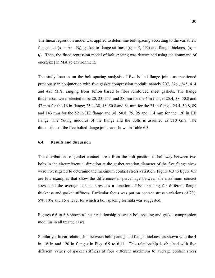
130
The linear regression model was applied to determine bolt spacing according to the variables:
flange size (x1 = Af – Bf), gasket to flange stiffness (x2 = Eg / Ef) and flange thickness (x3 =
tf). Then, the fitted regression model of bolt spacing was determined using the command of
ones(size) in Matlab environment.
The study focuses on the bolt spacing analysis of five bolted flange joints as mentioned
previously in conjunction with five gasket compression modulii namely 207, 276 , 345, 414
and 483 MPa, ranging from Teflon based to fiber reinforced sheet gaskets. The flange
thicknesses were selected to be 20, 23, 25.4 and 28 mm for the 4 in flange; 25.4, 38, 50.8 and
57 mm for the 16 in flange; 25.4, 38, 48, 50.8 and 64 mm for the 24 in flange; 25.4, 50.8, 89
and 143 mm for the 52 in HE flange and 38, 50.8, 75, 95 and 114 mm for the 120 in HE
flange. The Young modulus of the flange and the bolts is assumed as 210 GPa. The
dimensions of the five bolted flange joints are shown in Table 6.3.
6.4 Results and discussion
The distributions of gasket contact stress from the bolt position to half way between two
bolts in the circumferential direction at the gasket reaction diameter of the five flange sizes
were investigated to determine the maximum contact stress variation. Figure 6.3 to figure 6.5
are few examples that show the differences in percentage between the maximum contact
stress and the average contact stress as a function of bolt spacing for different flange
thickness and gasket stiffness. Particular focus was put on contact stress variations of 2%,
5%, 10% and 15% level for which a bolt spacing formula was suggested.
Figures 6.6 to 6.8 shows a linear relationship between bolt spacing and gasket compression
modulus in all treated cases
Similarly a linear relationship between bolt spacing and flange thickness as shown with the 4
in, 16 in and 120 in flanges in Figs. 6.9 to 6.11. This relationship is obtained with five
different values of gasket stiffness at four different maximum to average contact stress

131
variation. The same trend is found with the 24 in and 52 in flange. As a result, the linear
regression model of bolt spacing as a function flange size, gasket to flange stiffness and
flange thickness was adopted.
For a 2% difference between maximum to average contact stress variation, the suggested bolt
spacing formulae is:
H 56.9 0.1 A B 1966.7 E /E 1.8 t (6.13)
for 5% stress difference:
H 52.2 0.2 A B 2390.6 E /E 2.3 t (6.14)
For 10% stress difference:
H 57.4 0.2 A B 2766.3 E /E 2.8 t (6.15)
And for 15% stress difference:
H 70.6 0.2 A B 3153.2 E /E 3.1 t (6.16)
Figures 6.12 to 6.15 show the different flanges the comparison of the values from formulae
and the actual bolt spacing as a function of the gasket compression modulus with a 15%
contact stress difference. The results agree with each and in particular for the large size
flanges. A similar result was found when the bolt spacing formula was tested with the flange
thickness variable. Figures 6.16 to 6.20 show the comparisons of the different flange sizes at
15% stress difference with five different gasket compression moduli.
With 5%, 10% and 15% stress difference between the maximum and average contact stresses
similar result were found. Table 6.1 shows the percentage error found between bolt spacing

132
and that estimated by the formula. The maximum error is found to be 41% obtained with the
4 in size flange at the 15% stress difference. It is suspected that the model used to estimate
the contact stress is not suitable for small size flanges. In fact the theory of circular beams on
elastic foundation used in this study is not suitable. Small size flanges behave like plates and
therefore should be treated as circular plates on elastic foundation.
When the percentage difference d between the maximum and average contact stresses is
higher than 5%, the bolt spacing formulae can be regrouped in one general formula as:
H 50.21 1.13d 0.2 A B 1864.5 88.09d EE 1.71 0.098d t (6.17)
Table 6. 1 % error in estimating bolt spacing with the formulas
% difference between
max contact stress
variation and
average
Flange sizes
2%
5%
10%
15%
4 in
16 in
24 in
52 in
120 in
34.4
4.5
8.6
9.3
6.6
28.8
5.8
8.7
9.5
5.7
35
4.5
14.7
15
7.3
41.4
3.5
12.1
16.5
6.5
By applying this general formula, the maximum percentage error in the estimation of bolt
spacing is 41% as shown in Table 6.2. However a maximum of 19 % error is obtained if the
smaller size flanges is not included.

133
Table 6. 2 % error in estimating bolt spacing with the general formula
% difference between
max contact stress
variation and
average
Flange sizes
5%
10%
15%
4 in
16 in
24 in
52 in
120 in
30
6
7
11
7
36
5
13
13
9
41
4
14
19
6
6.5 Conclusion
This study proposes a methodology based on a linear regression approach to determine a bolt
spacing formula for bolted flange joints. The methodology relies on a proposed analytical
model based on the theory of circular beams on linear elastic foundation. A general formula
is proposed based on flange size, flange thickness and gasket to flange stiffness ratio. It was
tested against five different bolted joint sizes and found that a relatively good estimation of
the bolt spacing is obtained. However, caution should be taken as to the use of these
proposed formulae in case of small size flanges because they behave like plates and circular
beam on elastic foundation theory is less suited for cases. This model could potentially be
used to improve bolt spacing designs and give guidance to achieve safe in-service bolt
replacement and hot retorque.

APPENDIX
Table 6. 3 Nominal flange dimensions of 4 in., 16 in., 24 in., 52 in. and 120 in. HE flange
Flange size
(in)
Af
in
(mm)
Bf
in
(mm)
C
in
(mm)
g0
in
(mm)
g1
in
(mm)
h
in
(mm)
4 in 10¾
(276)
3⅝
(92)
8½
(216)
¼
(6)
1
(25.4)
2
(50.8)
16 in 25½
(648)
16½
(419)
22½
(572)
¼
(6)
1
(25.4)
2
(50.8)
24 in 29½
(749)
23¼
(590)
27⅝
(701)
⅜
(10)
⅝
(16)
1½
(38)
52 in 58⅜
(1483)
51
(1295)
56¼
(1429)
⅝
(16)
1⅛
(29)
1¼
(32)
120 in 127
(3226)
120¼
(3055)
124½
(3162)
⅝
(16)
1⅛
(29)
3⅛
(32)

135
Flange size
(in)
tf
in
(mm)
nb db
in
(mm)
Ag
in
(mm)
N
in
(mm)
4 in 0.8(20)
0.9(23)
1(25.4)
1.1(28)
12
8
4
4
1(25.4)
1¼(32)
1½(38)
1½(38)
5⅜
(142)
½
(12.7)
16 in 1½(38)
1¾(48)
2(50.8)
2¼(57)
20,16,12,8,4
1(25.4)
1¼(32)
1½(38)
1½(38)
18¼
(464)
½
(12.7)
24 in 1
1½(38)
1¾(48)
2(51)
32,28,24,20
16,12,8
1(25.4)
1¼(32)
1½(38)
1½(38)
24½
(622)
½
(12.7)
52 in 2(51)
3½ (89)
5⅝(143)
5⅝(143)
72,68,64,60
56,52,48,44
40,36,32,28
24,20,16
12,8
1(25.4)
1¼(32)
1½(38)
1½(38)
53⅛
(1349)
½
(12.7)
120 in 3(75)
4½(114)
6½(165)
84,80,76,72
68,64,60,56
52,48,44,40
36,32,28,24
20,16,12,8
1(25.4)
1¼(32)
1½(38)
123
(3124)
½
(12.7)

136
Figure 6. 1 Bolted flange joint
Figure 6. 2 Bolt spacing of the joint

137
Figure 6. 3 % different between maximum and average contact stress; 24 in. HE flange
Figure 6. 4 % different between maximum and average contact stress; 52 in. HE flange
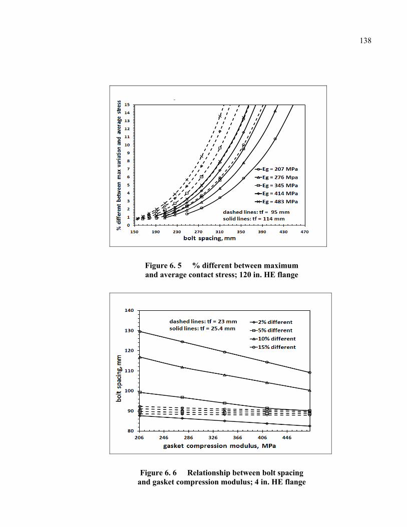
138
Figure 6. 5 % different between maximum and average contact stress; 120 in. HE flange
Figure 6. 6 Relationship between bolt spacing and gasket compression modulus; 4 in. HE flange

139
Figure 6. 7 Relationship between bolt spacing and gasket compression modulus; 16 in. HE flange
Figure 6. 8 Relationship between bolt spacing and gasket compression modulus; 24 in. HE flange

140
Figure 6. 9 Relationship between bolt spacing and flange thickness; 4 in. HE flange
Figure 6. 10 Relationship between bolt spacing and flange thickness; 16 in. HE flange

141
Figure 6. 11 Relationship between bolt spacing and flange thickness; 120 in HE flange
Figure 6. 12 Relationship between bolt spacing regression and gasket compression modulus; 4 in HE flange

142
Figure 6. 13 Relationship between bolt spacing regression and gasket compression modulus; 16 in HE flange
Figure 6. 14 Relationship between bolt spacing regression and gasket compression modulus; 52 in HE flange

143
Figure 6. 15 Relationship between bolt spacing regression and gasket compression modulus; 120 in HE flange
Figure 6. 16 Relationship between bolt spacing regression and flange thickness; 4 in HE flange

144
Figure 6. 17 Relationship between bolt spacing regression and flange thickness; 16 in HE flange
Figure 6. 18 Relationship between bolt spacing regression and flange thickness; 24 in HE flange

145
Figure 6. 19 Relationship between bolt spacing regression and flange thickness; 52 in HE flange
Figure 6. 20 Relationship between bolt spacing regression and flange thickness; 120 in HE flange

REFERENCES
[1] ASME Boiler and Pressure Vessel Code, 2001, Section VIII, Division 2, Appendix 2, Rules for Bolted Flange Connections with Ring Type Gaskets.
[2] EN 1591-1:2001 E, Flanges and their joints – Design rules for gasketed circular flange
connections Part 1: Calculation method. [3] Waters, E, O., Rossheim, D.B., Wesstrom, D.B. and Williams, F.S.G., 1937, “Formulas for
Stresses in Bolted Flanged Connections,” Transactions of the ASME, 59, pp. 161-169. [4] Waters, E, O., Rossheim, D.B., Wesstrom, D.B. and Williams, F.S.G., 1949, Development of
General Formulas for Bolted Flanges, Taylor Forge and Pipe Works, Chicago, Illinois. [5] G&W Taylor-Bonney Division, 1978, “Modern Flange Design”, Bulletin 502, Edition VII,
Southfield, Michigan. [6] George P. B., 1959, Standards of Tubular Exchanger Manufacturers Association, TEMA,
N.Y. 10017. [7] M’hadheb Mustapha, 2005, Effet de L’Espacement des Boulons Sur la Distribution des
Contraintes Dans Un Assemblage À Brides Boulonnées Muni d’un Joint d’Étanchéité, Master thesis, École de technologie supérieure.
[8] Nechache A. and Bouzid A., 2007, “Creep Analysis of Bolted Flange Joints,” International
Journal of Pressure Vessel and Piping, Vol. 84, no 3, pp. 185-194. [9] Lehnhoff, T. F.; McKay, M. L.; Bellora, V. A., 1992, “Member stiffness and bolt spacing of
bolted joints,” American Society of Mechanical Engineers, Pressure Vessels and Piping Division, PVP, v 248, Recent Advances in Structural Mechanics - 1992, pp. 63-72.
[10] McKee, R., Reddy, H., 1995, “Apparent Stiffness of a Bolted Flange,” American Society of
Mechanical Engineers Design Engineering Division, DE-Vol. 83, no 2 Pt 2, Computer Integrated Concurrent Design Conference, pp. 877-883.
[11] Roberts, I., 1950, “Gaskets and Bolted Joints,” Journal of Applied Mechanics, pp. 69-179. [12] Kilborn, D.F., 1975, “Spacing of Bolts in Flanged Joints,” 87 Ser A., no 7, pp. 339-342. [13] Koves. W. J., 2007, “Flange Joint Bolt Spacing Requirements,” Proceedings of 2007 ASME
Pressure Vessel and Piping Division Conference, PVP Vol. 3, p 3-10. [14] Bouzid, A. H., and Champliaud, H., 2004, “Contact Stress Evaluation of Nonlinear Gaskets
Using Dual Kriging Interpolation,” Journal of Pressure Vessel Technology, Vol. 126, no 4, pp. 445- 450.

147
[15] Volterra et al., 1974, Advanced Strength of Materials, Prentice-Hall, INC., Engewood Cliffs,
N.J., pp. 379-424. [16] Tan Dan Do, Bouzid. A. H., Thien-My Dao, 2008, “Effect of Bolt Spacing on the
Circumferential Distribution of Gasket Contact Stress in Bolted Flange Joints”, 16thInternational Conference on Nuclear Engineering, ICONE16, Paper No ICONE16- 48634, ASME, Orlando, Florida.
[17] Tan Dan Do, Bouzid. A. H., Thien-My Dao, 2010, “Effect of Bolt Spacing on the
Circumferential Distribution of Gasket Contact Stress in Bolted Flange Joints” Accepted, the Journal of Pressure Vessel Technology, Paper No PVT-10-1031.
[18] Tan Dan Do, Bouzid A. H., Thien-My Dao, 2010, “On the Use of the Theory of Ring on
Non-Linear Elastic Foundation to Study the Effect of Bolt Spacing in Bolted Flange Joints”, 2010 ASME-PVP Conference , Paper No PVP2010-26001, Bellevue, Washington.
[19] Tan Dan Do, Bouzid A. H., Thien-My DAO, 2010, “On the Use of the Theory of Ring on
Non-Linear Elastic Foundation to Study the Effect of Bolt Spacing in Bolted Flange Joints”, Submitted to the Journal of Pressure Vessel Technology.
[20] Martin Braun, 1983, Differential Equations and Their Applications, Sringer-Verlag, Third
Edition, USA. [21] Douglas C. Montgomery, 2009, Statistical Quality Control, John Wiley & Sons, Inc., pp.
150-169. [22] Matlab software, 2005, version 7.0.4.365, Release 14.

CONCLUSION
An accurate approach to developing a design procedure for bolted flange joints has been
presented. This approach considers an analytical model that includes the flexibility of all
joint members and is based on both the theories of linear and non-linear foundation behavior.
The proposed method is capable of examining joint structural integrity, as well as the
tightness behavior of the joint. Numerical results have been presented which show the effect
of initial bolt-up stress, and the distribution of gasket contact stresses on the circumferential
direction at the gasket reaction position. A simplified method to estimate bolt spacing of
bolted flange joints could ultimately become widely used in practical industrial applications.
Using this model, it could be possible to apply lower assembly loads with an adequate safety
margin while providing the required clamping force to maintain joint tightness during
operation. Therefore, gasket overload and excessive flange rotation may also conceivably be
avoided. In addition, the joint may further be lightened by reducing the flange thickness and
bolting, which is beneficial not only in terms of material savings but in overall costs savings
as well.
The tightness of the joint is achieved by combining the gasket mechanical properties and the
flange assembly and external forces. The most important factor which determines the
tightness behavior is the gasket contact stresses. As a result, the higher the gasket stresses, the
higher the tightness of the joint and the lower the likelihood of leakage in the joint. Thus,
information on gasket contact stress distributions and their variations is helpful in bolted
flange joint design procedures, which for their part, are based on the leakage behavior of
joints.
The initial bolt load has a major role in the performance of the bolted flange joint. Over-
tightening of the bolt load may lead to of gasket failure. The maximum allowable gasket
preload is limited by flange stresses, bolt stress and gasket crushes. Optimal design of initial
bolt-up stress and pressurized systems can be realized, allowing observance of environmental
safety standards and increasing the reliability of industrial facilities. Mastery of the tightness
behavior of bolted flange joints is taken into account. Bolt spacing is determined according to

149
the appropriate level of gasket contact stress variations to adopt with specific bolted joint
assembly and disassembly applications. It is necessary to define the gasket contact stress
variations to avoid the leakage that may occur in such system. It means that the contact stress
variations should remain below a certain threshold established to ensure safe operations, and
in some cases, by environmental protection standards. The behavior of different elements of
the assembly during loading and unloading, and particularly in the application of
temperature, must be taken into consideration during design.
The ASME flange design standard is not based on the leakage behavior of the system, and is
not taking into account the elastic interaction of different elements of the assembly. Bolted
flange joint designers rely on their experiences to estimate the leakage and follow the code
rules.
Various research endeavors undertaken within the framework of the present thesis have
developed an analytical model used to estimate flange displacement and gasket contact stress
distributions and their variations on bolted flange joints. This research focuses on the effect
of the gasket contact stress variations of the assembly on the circumferential direction at the
gasket reaction position.
The analytical model developed can evaluate the effect of bolt spacing on the tightness
behavior of the assembly according to different sizes of bolted flange joints. The research
presented in this thesis has three phases. The first step is to develop an analytical model of
the flange. It should be noted that in this stage, the flange is assumed to be a circular beam
resting on a linear elastic foundation. An analytical model based on the theory of a circular
beam on an linear elastic foundation is proposed to investigate the effect of bolt spacing on
the circumferential distribution of gasket contact stress of a 24-inch and 52-inch HE flange
has been developed. For the 24 in HE flange, the difference in the gasket contact stress
variations with respect to the average value is 25% for a flange thickness of 38 mm, gasket
Young modulus is 2 GPa and bolt number is 16 bolts. For the 52 in HE flange, it is 27% for a
flange thickness of 89 mm, gasket Young modulus is 3.5 GPa and bolt number is 24 bolts.

150
This current research gives more information than Koves model and it is adapted for more
research on nonlinear gasket behavior solution.
In the second stage, the non-linear behavior of the foundation is taken into account, and may
evaluate the tightness behavior of the joints by investigating the contact stress variations in
the circumferential direction at the gasket reaction position from bolt position to mid-bolt
position. The proposed analytical model was compared to a 3-D finite element numerical
model in order to validate the proposed theory. The results of the analytical model are in
good agreement with those of the 3-D finite element model. It should be noted that the
displacements of the linear and non-linear analytical solutions are quite similar in magnitude
and distribution, and compare relatively well with those of the FEA. The proposed analytical
model, based on the theory of a circular beam on a non-linear elastic foundation, for use in
investigating the effect of bolt spacing on the circumferential distribution of 52-inch and 120-
inch HE flange gasket contact stress has been created. For the 52 in HE flange; flange
thickness is 50.8 mm the difference in the gasket contact stress variations with respect to the
average value is 7.95% for a bolt number of 32 bolts, and 1.62% for a bolt number of 48
bolts. For the 120 in HE flange; flange thickness is 75 mm it is 8.05% for a bolt number of 56
bolts and 3.77% for a bolt number of 68 bolts.
The results show that when the flange thickness is greater than 115 millimeters for the 52-
inch HE flange, the bolt spacing may be not affected by the contact stress variations. The
same conclusion can be drawn for the 120-inch HE flange when the flange thickness is
greater than 135 millimeters. This model could potentially be used to improve the bolt
spacing design procedure.
The third step is focused on the linear relationship between the bolt spacing and flange Young
modulus, gasket compression modulus and flange thickness. The linear regression model was
applied to determine the appropriate bolt spacing values on the response variables, namely,
flange sizes, gasket Young’s modulus and flange Young’s modulus of bolted flange joints,
according to different maximum contact stresses compared to the average contact stress. The

151
proposed model is valid for different raised face type bolted flange joints, namely, 4-inch, 16-
inch, 24-inch, 52-inch and 120-inch heat exchanger flanges. The behaviors of Teflon based to
fiber reinforced sheet gaskets are examined in the analysis. The analytical solution evaluates
the bolt spacing based on the percentage between the maximum gasket contact stress
variations and the average contact stress of the joint. To realize the analytical model for
application, the linear regression model will be developed in order to provide the same
formula for five bolted flange joints sizes. Although the maximum residual emax (%) of 4 in
the HE flange is big, in most of the cases, the linear bolt spacing regressions are in good
agreement with the analytical model results. This model could potentially be used to improve
bolt spacing design and provide guidance to achieving safe in-service bolt replacement and
hot retorque.

RECOMMENDATIONS
The state of the art of bolted flange joints involves a number of variables that are difficult to
predict and control; these variables include internal pressure, external moments and forces,
gasket behavior, materials of bolt, flange and gasket, service temperatures, relaxation and
vibration of the system. The proposed analytical model is believed to be capable of
predicting with reasonable accuracy the effect of initial bolt-up and pressurization of raised
face type bolted flange joints incorporated into some gasket types. Some of the other
parameters mentioned above could readily be involved in this model.
The analytical model needs to be supported by the experiments. In future, experiments must
be done to validate our model.
The analytical model based on theory of ring on non-linear elastic foundation does not give
good results for 4 inch HE flange. Theory of plates is proposed to apply for small flange sizes
It is well established that the leakage behavior of joints is a function of the average gasket
contact stress of the joint and its variations on the circumferential direction at the gasket
reaction position. Therefore, the average contact stress and its variations must be investigated
in greater detail in order to relate it to tightness performance.
The effect of the gasket width and the influence of flange rotations on the tightness behavior
of joints also need to be further investigated and examined. The behaviors of the new gasket
types and materials obtained from room temperature tests need to be accounted for new
research studies.
Another major concern with bolted flange joints is the elevated temperature behavior of
joints and the effect of temperature on their leakage characteristics. The effect of vibration of
the system may also be an important factor that influences the tightness behavior of the joint.
The study of bolted flange joints involves a large number of parameters that are generally

153
difficult to identify. We recommend this work to allow a more thorough examination of the
following elements:
- The analytical analysis and finite element model must be validated through
experimental tests,
- The study of full face and metal-to-metal contact type bolted flange joints and the
behavior of different gasket must be considered,
- The thermal characterization of joints, the determination of the coefficient of
expansion and thermal conduction may be examined in future works,
- The study of bolted flange joints manufactured using composite materials.
In addition, full face and metal-to-metal contact type bolted flange joints should be
investigated in future works.
APPENDIX I
ANSYS PROGRAM: SOLUTION FOR 120 INCHES HE FLANGE
finish
/clear
/prep7
!==================
! 120 inches HE flange
!==================
*afun,deg ! unit of angle is degrees
!nb=84
!teta=360/nb/2-360/nb/3.5
!teta1=360/nb/2
!nb=84
!nb=68
nb=56
teta=360/nb/2-360/nb/3.5
teta1=360/nb/2
pi=3.1415926535897932384626433832795
!=================
! Define the elements
!=================
et,1,solid185 ! Solid element

155
!===================
! define flange’s material
!===================
uimp,1,ex,nuxy,alpx,30e6,0.3,12.5e-6
tb,creep,1,,,1
TBDATA,1,9.357e-29,5.5,0,0,
!=================
! define bolt’s material
!=================
uimp,2,ex,nuxy,alpx,30e6,0.3,14e-6
!===================
! define material for space
!===================
uimp,3,ex,nuxy,alpx,50,0.3,12.5e-12
MP,ALPX,4,3e-6
delta0 = 0.00e-3
stiff0 = 0.0e7
scap = 1.0e-5
!======================
! Define gasket characteristics
!======================

156
TB,GASKET,4,,,para
TBDATA, 1,delta0,stiff0,scap
!========================
! define gasket compression data
!========================
tb,gask,4,1,8,comp
tbpt,,0, 0
tbpt,,0.0054/2, 1047
tbpt,,0.0095/2, 2500
tbpt,,0.0119/2, 4550
tbpt,,0.0137/2, 8061
tbpt,,0.0156/2, 13360
tbpt,,0.0180/2, 24732
tbpt,,0.0199/2, 40000
!================
! List Gasket Material
!================
tblist,gask,all
tbplot,gask,4
!uimp,5,ex,nuxy,alpx,30e6,0.3,12.5e-6
uimp,5,ex,nuxy,alpx,30e10,0.3,12.5e-6
!=================
! define material of hub
!=================

157
uimp,6,ex,nuxy,alpx,30e6,0.3,12.5e-6
tb,creep,6,,,1
TBDATA,1,9.357e-29,5.5,0,0,
!=================
! define material of tube
!=================
uimp,7,ex,nuxy,alpx,30e6,0.3,12.5e-6
tb,creep,7,,,1
TBDATA,1,9.357e-29,5.5,0,0,
!==============
! define parameters
!==============
jeu=0
eps=0.00001
!===============
! the units are inches
!===============
ric= 120.25/2
ts=0.625
roc=ric+ts
g1=1.125

158
rocol=ric+g1
rop=127/2
h=3.125
!tf=6.5
!tf=4.5
!tf=2.9375
tf=1.5
rig=122/2
rog=123/2
G=rog-rig
rfs=rog
!===================
! bolt parameters (UNC)
!===================
D=1 ! nominal diameter of bolt (inches)
n=8 ! number of threads/inches (coarse thread)
As=(pi/4)*(D-0.9743/n)**2 ! tensile stress area
Ar=(pi/4)*(D-1.3/n)**2 ! root area
rmb=124.5/2 ! C = bolt circle (po)
rb=sqrt(Ar/pi)
rob=rmb+rb
rpb=1.25*D/2
roecrou=rmb+rpb
rtb=rb+0.01 !0.125/2
rotrou=rmb+rtb

159
rf=rfs !2.008*rmb-rop
radd=rtb+(rmb-rog-rtb)/2
hecrou=0.875*D
tj=0.063
efs=1e-4
r1=ric+ts/2
!===========
! input loads
!===========
pbolt=40000 ! initial pressure in bolts
!preserage=pbolt*84/84
!preserage=pbolt*84/68
!preserage=pbolt*84/56
preserage=pbolt*84/nb
pression=0
presseq=pression*(rog-G/2)**2/(roc**2-ric**2)
!=======================
! define the position of elements
!=======================
z1=0
z2=tj/2
z3=z2+efs

160
z4=z3+tf
z5=z4+hecrou
z6=z4+h
z7=z6+10*sqrt(ts*(ric+roc)/2)
csys,1
k,1,rog,0,z3
k,2,rog,teta,z3
k,3,rop,0,z3
k,4,rop,teta,z3
L,1,2
L,3,4
k,9,rf,0,z4
k,10,rf,teta,z4
k,11,rop,0,z4
k,12,rop,teta,z4
L,9,10
L,11,12
LOCAL, 11, 1, rmb, 0, 0
k,5,radd,0,z3
k,6,radd,45,z3
k,7,radd,135,z3
k,8,radd,180,z3
L,5,6
L,6,7
L,7,8

161
k,13,rpb,0,z4
k,14,rpb,45,z4
k,15,rpb,135,z4
k,16,rpb,180,z4
L,13,14
L,14,15
L,15,16
!/eof
csys,0
L,1,9
L,2,10
L,3,11
L,4,12
L,5,13
L,6,14
L,7,15
L,8,16
L,1,8
L,5,3
L,2,7
L,4,6
L,2,4
L,9,16
L,13,11
L,10,15

162
L,12,14
L,10,12
type,1
mat,1
kmax=8
V, 1, 8, 7, 2, 1+kmax, 8+kmax, 7+kmax, 2+kmax
V, 7, 6,4,2, 7+kmax, 6+kmax, 4+kmax, 2+kmax
V, 6,5, 3,4, 6+kmax, 5+kmax, 3+kmax, 4+kmax
!vplot
!/eof
csys,1
k,17,ric,0,z3
k,18,ric,teta,z3
k,19,rig,0,z3
k,20,rig,teta,z3
k,21,rocol,0,z3
k,22,rocol,teta,z3
k,23,ric,0,z4
k,24,ric,teta,z4
k,25,rig,0,z4
k,26,rig,teta,z4

163
k,27,rocol,0,z4
k,28,rocol,teta,z4
k,29,ric,0,z6
k,30,ric,teta,z6
k,31,r1,0,z6
k,32,r1,teta,z6
k,33,roc,0,z6
k,34,roc,teta,z6
k,35,ric,0,z7
k,36,ric,teta,z7
k,37,r1,0,z7
k,38,r1,teta,z7
k,39,roc,0,z7
k,40,roc,teta,z7
!=============
! create flange
!=============
vsel,none
v,17,19,20,18,23,25,26,24
v,19,21,22,20,25,27,28,26
v,21,1,2,22,27,9,10,28
vatt,1,0,1

164
!alls
!vplot
!/eof
!=====
!—Hub
!=====
vsel,none
v,23,25,26,24,29,31,32,30
v,25,27,28,26,31,33,34,32
vatt,6,0,1
!========
!—tube
!========
vsel,none
v,29,31,32,30,35,37,38,36
v,31,33,34,32,37,39,40,38
vatt,7,0,1
!alls
!vplot
!/eof
!=====================
! create bolts
!=====================

165
LOCAL, 11, 1, rmb, 0, 0
k,43,0,0,z1
k,44,(rob-rmb),0,z1
k,45,(rob-rmb),45,z1
k,46,(rob-rmb),135,z1
k,47,(rob-rmb),180,z1
k,51,0,45,z3
k,52,(rob-rmb),0,z3
k,53,(rob-rmb),45,z3
k,54,(rob-rmb),135,z3
k,55,(rob-rmb),180,z3
k,59,0,0,z4+jeu
k,60,(rob-rmb),0,z4+jeu
k,61,(rob-rmb),45,z4+jeu
k,62,(rob-rmb),135,z4+jeu
k,63,(rob-rmb),180,z4+jeu
k,67,(rotrou-rmb),0,z4+jeu
k,68,(rotrou-rmb),45,z4+jeu
k,69,(rotrou-rmb),135,z4+jeu
k,70,(rotrou-rmb),180,z4+jeu
k,71,(roecrou-rmb),0,z4+jeu
k,72,(roecrou-rmb),45,z4+jeu
k,73,(roecrou-rmb),135,z4+jeu
k,74,(roecrou-rmb),180,z4+jeu

166
k,75,0,0,z5
k,76,(rob-rmb),0,z5
k,77,(rob-rmb),45,z5
k,78,(rob-rmb),135,z5
k,79,(rob-rmb),180,z5
k,83,(rotrou-rmb),0,z5
k,84,(rotrou-rmb),45,z5
k,85,(rotrou-rmb),135,z5
k,86,(rotrou-rmb),180,z5
k,87,(roecrou-rmb),0,z5
k,88,(roecrou-rmb),45,z5
k,89,(roecrou-rmb),135,z5
k,90,(roecrou-rmb),180,z5
vsel,none
v,43,44,45,51,52,53
v,43,45,46,51,53,54
v,43,46,47,51,54,55
vatt,2,0,1
vsel,none
v,51,52,53,59,60,61
v,51,53,54,59,61,62
v,51,54,55,59,62,63
vatt,2,0,1
vsel,none
v,59,60,61,75,76,77

167
v,59,61,62,75,77,78
v,59,62,63,75,78,79
vatt,2,0,1
vsel,none
v,60,67,68,61,76,83,84,77
v,61,68,69,62,77,84,85,78
v,62,69,70,63,78,85,86,79
vatt,2,0,1
vsel,none
v,67,71,72,68,83,87,88,84
v,68,72,73,69,84,88,89,85
v,69,73,74,70,85,89,90,86
vatt,2,0,1
!alls
!vplot
!/eof
!==============================
! create space between bolts and flange
!==============================
k,99,rotrou-rmb,0,z3
k,100,rotrou-rmb,45,z3
k,101,rotrou-rmb,135,z3
k,102,rotrou-rmb,180,z3
k,103,rotrou-rmb,0,z4

168
k,104,rotrou-rmb,45,z4
k,105,rotrou-rmb,135,z4
k,106,rotrou-rmb,180,z4
k,115,(rob-rmb)+jeu,0,z3
k,116,(rob-rmb)+jeu,45,z3
k,117,(rob-rmb)+jeu,135,z3
k,118,(rob-rmb)+jeu,180,z3
k,119,(rob-rmb)+jeu,0,z4
k,120,(rob-rmb)+jeu,45,z4
k,121,(rob-rmb)+jeu,135,z4
k,122,(rob-rmb)+jeu,180,z4
vsel,none
v,99,5,6,100,103,13,14,104
v,100,6,7,101,104,14,15,105
v,101,7,8,102,105,15,16,106
vatt,1,0,1
vsel,none
v,115,99,100,116,119,103,104,120
v,116,100,101,117,120,104,105,121
v,117,101,102,118,121,105,106,122
vatt,3,0,1
csys,1
k,123,ric,0,z2
k,124,ric,teta,z2

169
k,125,rig,0,z2
k,126,rig,teta,z2
k,127,rocol,0,z2
k,128,rocol,teta,z2
k,129,rfs,0,z2
k,130,rfs,teta,z2
vsel,none
v,123,125,126,124,17,19,20,18
v,125,127,128,126,19,21,22,20
v,127,129,130,128,21,1,2,22
vatt,7,0,1
alls
vplot
!/eof
csys,1
k,131,ric,teta1,z3
k,132,rig,teta1,z3
k,133,rocol,teta1,z3
k,134,rog,teta1,z3
k,135,rop,teta1,z3
k,136,ric,teta1,z4
k,137,rig,teta1,z4

170
k,138,rocol,teta1,z4
k,139,rf,teta1,z4
k,140,rop,teta1,z4
k,141,ric,teta1,z6
k,142,r1,teta1,z6
k,143,roc,teta1,z6
k,144,ric,teta1,z7
k,145,r1,teta1,z7
k,146,roc,teta1,z7
vsel,none
v,18,20,132,131,24,26,137,136
v,20,22,133,132,26,28,138,137
v,22,2,134,133,28,10,139,138
v,2,4,135,134,10,12,140,139
vatt,1,0,1
!===========
!—Hub
!===========
vsel,none
v,24,26,137,136,30,32,142,141
v,26,28,138,137,32,34,143,142
vatt,6,0,1

171
!============
! tube
!============
vsel,none
v,30,32,142,141,36,38,145,144
v,32,34,143,142,38,40,146,145
vatt,7,0,1
alls
vplot
!/eof
csys,1
k,147,ric,teta1,z2
k,148,rig,teta1,z2
k,149,rocol,teta1,z2
k,150,rfs,teta1,z2
vsel,none
v,124,126,148,147,18,20,132,131
v,126,128,149,148,20,22,133,132
v,128,130,150,149,22,2,134,133
vatt,7,0,1
alls
csys,11
172
lsel,s,line,,100
lesize,all,,,8
lsel,s,line,,145
lesize,all,,,6
lsel,s,line,,150
lesize,all,,,6
lsel,s,line,,155
lesize,all,,,6
csys,1
lsel,s,line,,13
lesize,all,,,8
lsel,s,line,,2,4,2
lesize,all,,,6
lsel,s,line,,23,28,5
lesize,all,,,6
lsel,s,line,,1,3,2
lesize,all,,,6
lsel,s,line,,46
lesize,all,,,6
lsel,s,line,,49,51,2
lesize,all,,,3

173
lsel,s,line,,20,25,1
lesize,all,,,6
lsel,s,line,,41,43,2
lesize,all,,,6
lsel,s,line,,29,31,2
lesize,all,,,3
lsel,s,line,,230,232,2
lesize,all,,,6
lsel,s,line,,231,234,3
lesize,all,,,6
lsel,s,line,,222
lesize,all,,,6
lsel,s,line,,55
lesize,all,,,8
lsel,s,line,,68
lesize,all,,,60
esize,0.5
vmesh,all
alls

174
et,2,195
csys,1
k,151,rig,0,z1
k,152,rocol,0,z1
k,153,rog,0,z1
k,154,rig,teta,z1
k,155,rocol,teta,z1
k,156,rog,teta,z1
k,157,rig,teta1,z1
k,158,rocol,teta1,z1
k,159,rog,teta1,z1
vsel,none
v,151,152,155,154,125,127,128,126
v,152,153,156,155,127,129,130,128
v,154,155,158,157,126,128,149,148
v,155,156,159,158,128,130,150,149
vatt,4,0,2
k,160,rig,0,-z2
k,161,rocol,0,-z2
k,162,rog,0,-z2
k,163,rig,teta,-z2
k,164,rocol,teta,-z2

175
k,165,rog,teta,-z2
k,166,rig,teta1,-z2
k,167,rocol,teta1,-z2
k,168,rog,teta1,-z2
vsel,none
v,160,161,164,163,151,152,155,154
v,161,162,165,164,152,153,156,155
v,163,164,167,166,154,155,158,157
v,164,165,168,167,155,156,159,158
vatt,5,0,1
alls
vplot
csys,1
lsel,s,line,,271
lesize,all,,,6
lsel,s,line,,208
lesize,all,,,6
lsel,s,line,,265
lesize,all,,,6
lsel,s,line,,195
lesize,all,,,6
lsel,s,line,,207
lesize,all,,,6
lsel,s,line,,270
lesize,all,,,6

176
lsel,s,line,,202
lesize,all,,,6
lsel,s,line,,262
lesize,all,,,6
lsel,s,line,,251
lesize,all,,,6
lsel,s,line,,279
lesize,all,,,6
lsel,s,line,,259
lesize,all,,,6
lsel,s,line,,280
lesize,all,,,6
imesh,area,140,189,0
vmesh,50
imesh,area,144,194,0
vmesh,51
imesh,area,183,198,0
vmesh,52
imesh,area,186,202,0
vmesh,53
alls
csys,11
nsel,s,loc,x,rotrou-rmb-eps,roecrou-rmb+eps
nsel,r,loc,y,0-eps,180+eps
nsel,r,loc,z,z4-eps,z4+jeu+eps

177
cpintf,ux,1.1*jeu
cpintf,uy,1.1*jeu
cpintf,uz,1.1*jeu
nsel,all
csys,11
nsel,s,loc,x,rb-eps,rtb+0.001
nsel,r,loc,y,0-eps,180+eps
nsel,r,loc,z,z3-eps,z4+jeu-eps
cpintf,ux,1.1*0.01
cpintf,uy,1.1*0.01
nsel,all
finish
!=======================
! solving the problem
!=======================
/solu
csys,11
nsel,s,loc,x,0-eps,(rob-rmb)+eps
nsel,r,loc,y,0-eps,180+eps
nsel,r,loc,z,z1-eps,z1+eps
asel,s,,,50
asel,a,,,55
asel,a,,,59

178
sfa,all,,pres,-preserage
csys,11
asel,s,,,50
asel,a,,,55
asel,a,,,59
nsla,s
CP,1,UZ,ALL
ALLS
csys,1
nsel,s,loc,x,rig-eps,rog+eps
nsel,r,loc,y,0-eps,teta1+eps
nsel,r,loc,z,z1-eps,z1+eps
d,all,uz,0
alls
csys,1
nsel,s,loc,x,ric-eps,rop+eps
nsel,r,loc,y,0-eps,0+eps
nsel,r,loc,z,-z2-eps,z7+eps
dsym,symm,y,1

179
csys,1
nsel,s,loc,x,ric-eps,rop+eps
nsel,r,loc,y,teta1-eps,teta1+eps
nsel,r,loc,z,-z2-eps,z7+eps
dsym,symm,y,1
ALLS
rate,off
deltim,1e-45,1e-46,1e-45
time,1e-45
kbc,1
OUTRES,ALL,ALL
alls
SOLVE ! fluage
finish
/post1
esel,s,mat,,4
SET, , ,1, ,0, ,
PLNSOL,GKS,X,0,1
alls
/eof
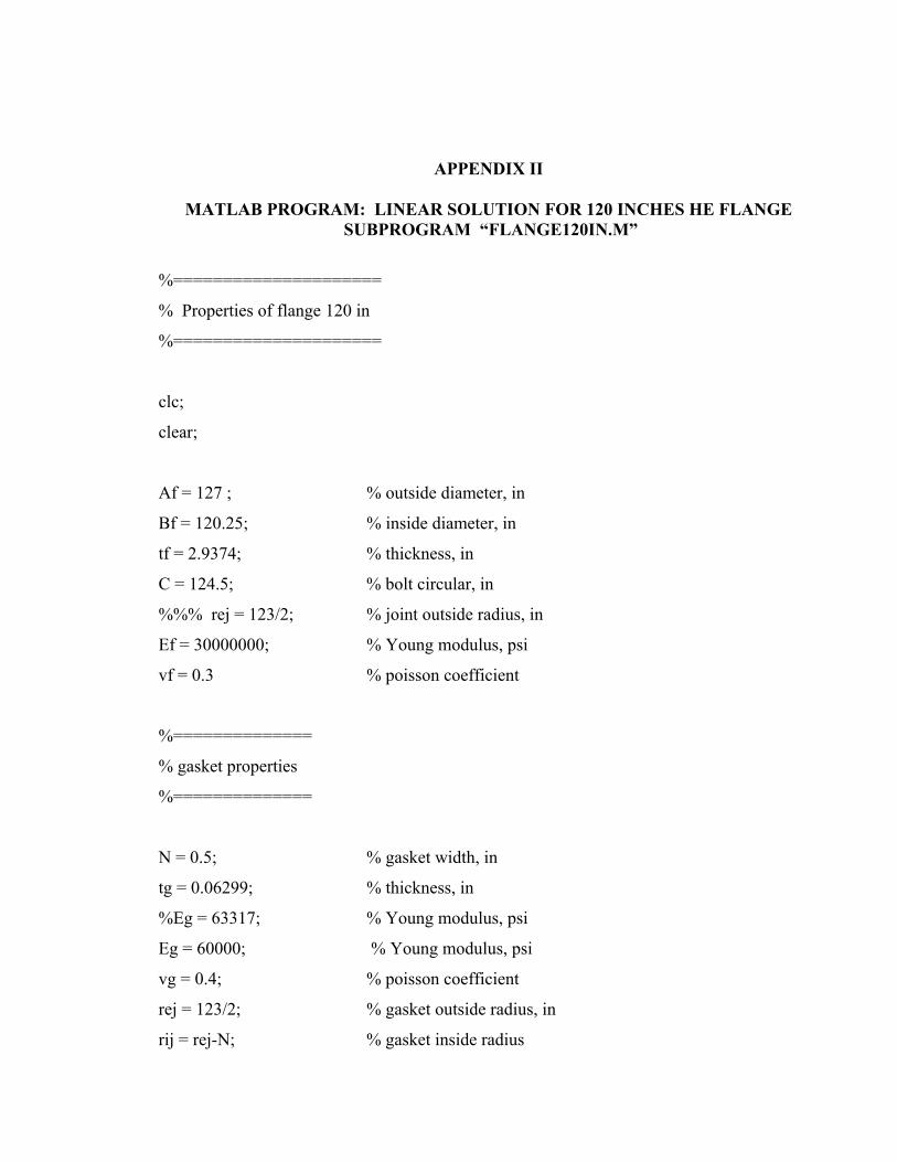
APPENDIX II
MATLAB PROGRAM: LINEAR SOLUTION FOR 120 INCHES HE FLANGE SUBPROGRAM “FLANGE120IN.M”
%=====================
% Properties of flange 120 in
%=====================
clc;
clear;
Af = 127 ; % outside diameter, in
Bf = 120.25; % inside diameter, in
tf = 2.9374; % thickness, in
C = 124.5; % bolt circular, in
%%% rej = 123/2; % joint outside radius, in
Ef = 30000000; % Young modulus, psi
vf = 0.3 % poisson coefficient
%==============
% gasket properties
%==============
N = 0.5; % gasket width, in
tg = 0.06299; % thickness, in
%Eg = 63317; % Young modulus, psi
Eg = 60000; % Young modulus, psi
vg = 0.4; % poisson coefficient
rej = 123/2; % gasket outside radius, in
rij = rej-N; % gasket inside radius
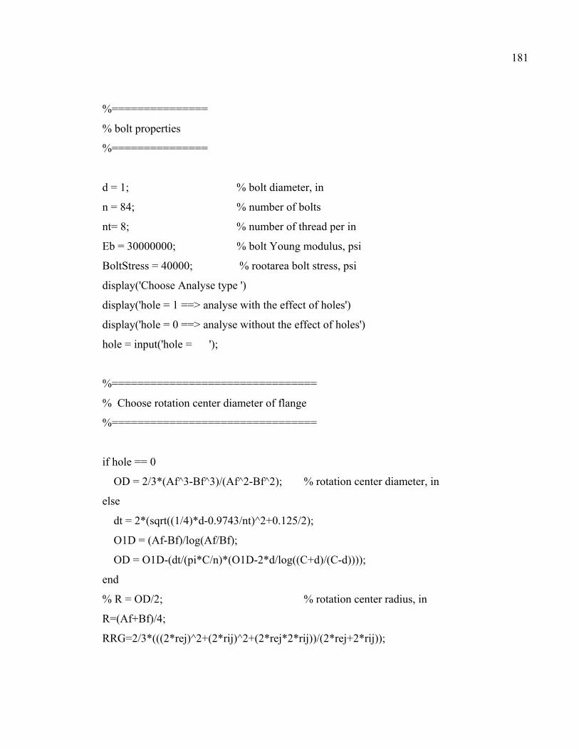
181
%===============
% bolt properties
%===============
d = 1; % bolt diameter, in
n = 84; % number of bolts
nt= 8; % number of thread per in
Eb = 30000000; % bolt Young modulus, psi
BoltStress = 40000; % rootarea bolt stress, psi
display('Choose Analyse type ')
display('hole = 1 ==> analyse with the effect of holes')
display('hole = 0 ==> analyse without the effect of holes')
hole = input('hole = ');
%================================
% Choose rotation center diameter of flange
%================================
if hole == 0
OD = 2/3*(Af^3-Bf^3)/(Af^2-Bf^2); % rotation center diameter, in
else
dt = 2*(sqrt((1/4)*d-0.9743/nt)^2+0.125/2);
O1D = (Af-Bf)/log(Af/Bf);
OD = O1D-(dt/(pi*C/n)*(O1D-2*d/log((C+d)/(C-d))));
end
% R = OD/2; % rotation center radius, in
R=(Af+Bf)/4;
RRG=2/3*(((2*rej)^2+(2*rij)^2+(2*rej*2*rij))/(2*rej+2*rij));

APPENDIX III
MATLAB PROGRAM: LINEAR SOLUTION FOR 120 INCHES HE FLANGE
%==========================================================
% Program to calculate deformation of circular beam on linear-elastic foundation
% Flange 120 inches
%==========================================================
clc;
clear;
flange120in
Gf = Ef/(2*(1+vf)); % shear modulus
In=OD*tf^3*log(Af/Bf)/24; % moment inertia
% Ib = ((Af-Bf)/2)^3*tf/12; % moment inertia Ib
% Ip = In+Ib; % moment polar inertia
% S = (Af-Bf)/2*tf; % surface area of section
G = 2/3*(((2*rej)^2+(2*rij)^2+(2*rej*2*rij))/(2*rej+2*rij)); % reaction diameter of gasket
hg = (R-G/2); % position of section centroid
K=16*((Af-Bf)/2)^3*(tf/2)*((1/3)-((64/(pi^5))*((Af-Bf)/tf)*tanh((pi*tf/2)/(Af-Bf))));
%==============
% bolt properties
%==============

183
StressArea = n*pi*(d-0.9743/nt)^2/4; % Forced suppoted Surface
RootArea = n*pi*(d-1.3/nt)^2/4; % root thread surface
LoadInBolt = BoltStress*RootArea; % bolt load, lb
Fb0 = (LoadInBolt/n)*C/OD; % load in each bolt, lb
gam1 = 360/n; % angle between 2 bolts, degree
gam = (gam1*pi/180)/2; % half angle between 2 bolts, radian
%========================
% applied repeated load on flange
%========================
qb = Fb0*n*(C-RRG)/(2*OD*pi);
Pb = 0; % outside repeated load on direction ob
%=================================
% Contribute the functions
%=================================
% y1 = v; % flange displacement
% y2 = beta; % bending angle
% y3 = teta; % twist rotation angle
% y4 = vb; % shear force
% y5 = Mn; % bending moment
% y6 = Mt; % torsion moment
Neff = N; % Neff initialization (joint effective width)
DN0 = 0.05*N; % variation admitted between N and Neff
while Neff <= N
K1 = Eg*Neff/(tg/2); % elastic foundation modulus

184
syms D w fa phi x C1 C2 C3 C4 C5 C6 v0 tta0 s v0 vp bet bp0 tta ttap
syms c1 c2 c3 c4 c5 c6
%================================
% bolt assembly equation system matrix
%================================
A = [0,1,0,0,0,0;
0,0,1/R,0,-1/(Ef*In),0;
0,-1/R,0,0,0,1/(Gf*K);
K1*G/OD,0,0,0,0,0;
0,0,0,1,0,-1/R;
K1*G*(OD-G)/(2*OD),0,0,0,1/R,0];
%==============
% load vector
%==============
gx = [0;0;0;-Fb0;0;qb];
%================================
% calculate the eigenvalues and eigenvector
%================================
[V,D] = eig(A);
reel = [];
for i=1:6
reel(i)=isreal(D(:,i));
end

185
reel; % identify the site of the complex values
sp = zeros(1,6);
z = zeros(1,6);
r = zeros(6,6);
m = zeros(6,6);
%======================
% solution of real eigenvalues
%======================
for i=1:6
j=reel(1,i);
if j==1; % real values
sp(1,i)=D(i,i);
r(:,i)=V(:,i);
M(:,i)=exp(sp(1,i)*x).*r(:,i);
end
end
%========================
% solution of eigenvalues complex
%========================
for i=1:6
j=reel(1,i);
if j==0; % value complex
z(1,i)=imag(D(i,i));
sp(1,i)=real(D(i,i));
r(:,i)=real(V(:,i));
m(:,i)=imag(V(:,i));
end

186
end
%========================
% seek eigenvalues
%========================
valconj=zeros(6,6);
for i=1:6
j=reel(1,i);
if j==0;
for k=i+1:6
if D(i,i)==conj(D(k,k))
valconj(i,k)=1;
end
end
end
end
%================================================
% assignment of the egeinvalues conjugees two by two and solution
%================================================
for i=1:6;
for j=i:6;
if valconj(i,j)==1
valconj(i+1:6,j)=0;
valconj(i,j+1:6)=0;
valconj(j,:)=0;
M(:,i)=exp(sp(i)*x)*(r(:,i)*cos(z(1,i)*x)-m(:,i)*sin(z(i)*x));
M(:,j)=exp(sp(i)*x)*(r(:,i)*sin(z(i)*x)+m(:,i)*cos(z(i)*x));

187
end
end
end
M;
%============================
% Calculate the initial condition vector
%============================
Y0=[c1;c2;c3;c4;c5;c6];
x=0
M0=eval(M); % evaluation of M at x=0
Ex=M*M0^-1;
E0=eval(Ex);
Ex1=Ex*E0;
x=-s;
Exs=eval(Ex); % evaluation of M at x=-s
%=================
% Calculate Y0
%=================
x = -gam*R; % coordinate curvilinear of the first bolt
Ex1m = eval(Ex1);
y11m = Ex1m(1,:); y21m = Ex1m(2,:); y31m = Ex1m(3,:);
y41m = Ex1m(4,:); y51m = Ex1m(5,:); y61m = Ex1m(6,:);
Exm = eval(Ex);
Ex2m = Exm*int(Exs*gx,s,0,-R*gam);
y12m = Ex2m(1,:); y22m = Ex2m(2,:); y32m = Ex2m(3,:);
y42m = Ex2m(4,:); y52m = Ex2m(5,:); y62m = Ex2m(6,:);

188
x = gam*R; % coordinate curvilinear of the second bolt
Ex1p = eval(Ex1);
y11p = Ex1p(1,:); y21p = Ex1p(2,:); y31p = Ex1p(3,:);
y41p = Ex1p(4,:); y51p = Ex1p(5,:); y61p = Ex1p(6,:);
Exp = eval(Ex);
Ex2p = Exp*int(Exs*gx,s,0,R*gam);
y12p = Ex2p(1,:); y22p = Ex2p(2,:); y32p = Ex2p(3,:);
y42p = Ex2p(4,:); y52p = Ex2p(5,:); y62p = Ex2p(6,:);
x = -gam*R+1e-16; % coordinate curvilinear at gam+
Ex1mp = eval(Ex1);
y41mp = Ex1mp(4,:); y61mp = Ex1mp(6,:);
Exp = eval(Ex);
Ex2mp = Exp*int(Exs*gx,s,0,-R*gam+1e-16);
y12mp = Ex2mp(1,:); y42mp = Ex2mp(4,:); y62mp = Ex2mp(6,:);
x = gam*R-1e-16; % coordinate curvilinear at gam-
Ex1pm = eval(Ex1);
y41pm = Ex1pm(4,:); y61pm = Ex1pm(6,:);
Exp = eval(Ex);
Ex2pm = Exp*int(Exs*gx,s,0,R*gam-1e-16);
y12pm = Ex2pm(1,:); y42pm = Ex2pm(4,:); y62pm = Ex2pm(6,:);
ch1 = -y12p+y12m;
ch2 = -y22p+y22m;
ch3 = -y32p+y32m;
ch4 = (-y62p+y62m)/(K*G)-(-y22p+y22m)/R;
ch5 = (-y32p+y32m)/R-(-y52p+y52m)/(Ef*In);
ch6 = Fb0+(-y42mp-y62mp/R+y42pm-y62pm/R);
%==============
% Load vector
%==============

189
Ch = [ch1;ch2;ch3;ch4;ch5;ch6];
%====================================================
% The equation system could be written as a function of B*Y0=Ch;
% Determine matrix B
%====================================================
By1 = y11p-y11m;
By2 = y21p-y21m;
By3 = y31p-y31m;
By4 = (y61p-y61m)/(K*G)-(y21p-y21m)/R;
By5 = (y31p-y31m)/R-(y51p-y51m)/(Ef*In);
By6 = (-y61mp+y61pm)/R+(y41mp-y41pm);
B = [By1;By2;By3;By4;By5;By6];
%==============
% Determine Y0
%==============
Y0 = inv(B)*Ch;
vpa(Y0);
%===========================
% numerical calculation of the solution
%===========================
SS = [];
j = 0;
for i = 0:gam/20:gam;
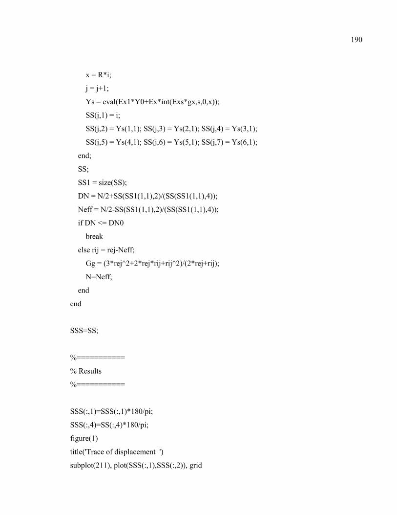
190
x = R*i;
j = j+1;
Ys = eval(Ex1*Y0+Ex*int(Exs*gx,s,0,x));
SS(j,1) = i;
SS(j,2) = Ys(1,1); SS(j,3) = Ys(2,1); SS(j,4) = Ys(3,1);
SS(j,5) = Ys(4,1); SS(j,6) = Ys(5,1); SS(j,7) = Ys(6,1);
end;
SS;
SS1 = size(SS);
DN = N/2+SS(SS1(1,1),2)/(SS(SS1(1,1),4));
Neff = N/2-SS(SS1(1,1),2)/(SS(SS1(1,1),4));
if DN <= DN0
break
else rij = rej-Neff;
Gg = (3*rej^2+2*rej*rij+rij^2)/(2*rej+rij);
N=Neff;
end
end
SSS=SS;
%===========
% Results
%===========
SSS(:,1)=SSS(:,1)*180/pi;
SSS(:,4)=SS(:,4)*180/pi;
figure(1)
title('Trace of displacement ')
subplot(211), plot(SSS(:,1),SSS(:,2)), grid

191
ylabel('y1: v = displacement');
xlabel('angle position alpha: degree');
subplot(212), plot(SSS(:,1), SSS(:,4)), grid
ylabel('y3: twist rotation angle teta: degree ')
xlabel('angle position alpha: degree')

APPENDIX IV
MATLAB PROGRAM: NON-LINEAR SOLUTION FOR 120 INCHES HE FLANGE SUBPROGRAM “RIGID52ODE.M”
function dy=rigid(t,y,param)
load param_save.mat
R = param(1);Ef = param(2);In = param(3);OD = param(4);G = param(5);K1 = param(6);K =
param(7);Gf = param(8);Pb = param(9);qb = param(10);exp(1)=param(11);
close all;
%%% nonlinear gasket behavior: q = K1*y^2
% dy=zeros(6,1);
% dy(1)=R*y(2);
% dy(2)=y(3)-y(5)*R/(Ef*In);
% dy(3)=-y(2)+y(6)*R/(K*Gf);
% dy(4)=R*G*K1*y(1)^2/OD-Pb*R;
% dy(5)=-y(6)+y(4)*R;
% dy(6)=y(5)+qb*R+(R*(OD-G)*G*K1*y(1)^2)/(2*OD);
%%% nonlinear gasket behavior: q = K1*y^3
% dy=zeros(6,1);
% dy(1)=R*y(2);
% dy(2)=y(3)-y(5)*R/(Ef*In);
% dy(3)=-y(2)+y(6)*R/(K*Gf);
% dy(4)=R*G*K1*y(1)^3/OD-Pb*R;
% dy(5)=-y(6)+y(4)*R;
% dy(6)=y(5)+qb*R+(R*(OD-G)*G*K1*y(1)^3)/(2*OD);

193
%%% nonlinear gasket behavior: Sg = 3.5e+11*y^4-0.5e+10*y^3+0.65e+8*y^2-56546*y
% dy=zeros(6,1);
% dy(1)=R*y(2);
% dy(2)=y(3)-y(5)*R/(Ef*In);
% dy(3)=-y(2)+y(6)*R/(K*Gf);
% dy(4)=R*G*(8500000*0.5^3*y(1)^4+900000*0.5^2*y(1)^3+112000000*0.5*y(1)^2-
235000*y(1))/OD-Pb*R;
% dy(5)=-y(6)+y(4)*R;
%dy(6)=y(5)+qb*R+(R*(OD-
G)*G*(8500000*0.5^3*y(1)^4+900000*0.5^2*y(1)^3+112000000*0.5*y(1)^2-
235000*y(1)))/(2*OD);
%%%q=K1*y: Test Program
% dy=zeros(6,1);
% dy(1)=R*y(2);
% dy(2)=y(3)-y(5)*R/(Ef*In);
% dy(3)=-y(2)+y(6)*R/(K*Gf);
% dy(4)=R*G*K1*y(1)/OD-Pb*R;
% dy(5)=-y(6)+y(4)*R;
% dy(6)=y(5)+qb*R+(R*(OD-G)*G*K1*y(1))/(2*OD);
%%% nonlinear gasket behavior: q = exp(1)^(K1*y)
% dy=zeros(6,1);
% dy(1)=R*y(2);
% dy(2)=y(3)-y(5)*R/(Ef*In);
% dy(3)=-y(2)+y(6)*R/(K*Gf);
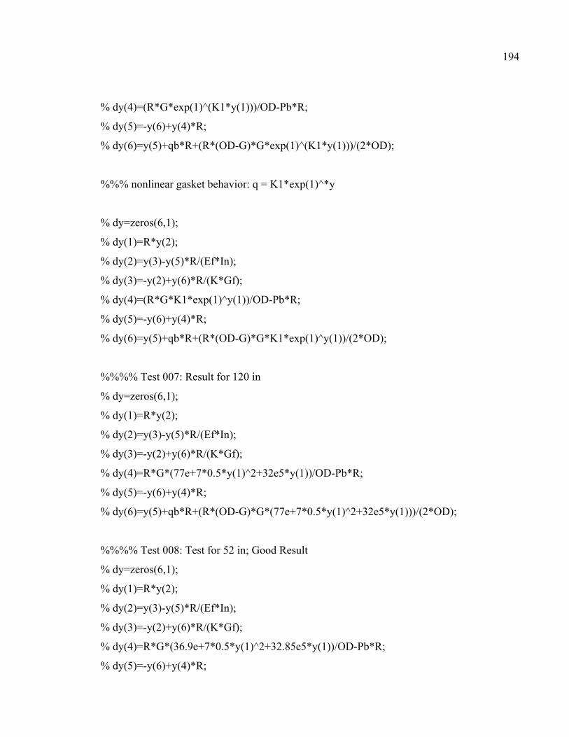
194
% dy(4)=(R*G*exp(1)^(K1*y(1)))/OD-Pb*R;
% dy(5)=-y(6)+y(4)*R;
% dy(6)=y(5)+qb*R+(R*(OD-G)*G*exp(1)^(K1*y(1)))/(2*OD);
%%% nonlinear gasket behavior: q = K1*exp(1)^*y
% dy=zeros(6,1);
% dy(1)=R*y(2);
% dy(2)=y(3)-y(5)*R/(Ef*In);
% dy(3)=-y(2)+y(6)*R/(K*Gf);
% dy(4)=(R*G*K1*exp(1)^y(1))/OD-Pb*R;
% dy(5)=-y(6)+y(4)*R;
% dy(6)=y(5)+qb*R+(R*(OD-G)*G*K1*exp(1)^y(1))/(2*OD);
%%%% Test 007: Result for 120 in
% dy=zeros(6,1);
% dy(1)=R*y(2);
% dy(2)=y(3)-y(5)*R/(Ef*In);
% dy(3)=-y(2)+y(6)*R/(K*Gf);
% dy(4)=R*G*(77e+7*0.5*y(1)^2+32e5*y(1))/OD-Pb*R;
% dy(5)=-y(6)+y(4)*R;
% dy(6)=y(5)+qb*R+(R*(OD-G)*G*(77e+7*0.5*y(1)^2+32e5*y(1)))/(2*OD);
%%%% Test 008: Test for 52 in; Good Result
% dy=zeros(6,1);
% dy(1)=R*y(2);
% dy(2)=y(3)-y(5)*R/(Ef*In);
% dy(3)=-y(2)+y(6)*R/(K*Gf);
% dy(4)=R*G*(36.9e+7*0.5*y(1)^2+32.85e5*y(1))/OD-Pb*R;
% dy(5)=-y(6)+y(4)*R;

195
% dy(6)=y(5)+qb*R+(R*(OD-G)*G*(36.9e+7*0.5*y(1)^2+32.85e5*y(1)))/(2*OD);
%%%% Test 009: Test for 52 in; Good Result
% dy=zeros(6,1);
% dy(1)=R*y(2);
% dy(2)=y(3)-y(5)*R/(Ef*In);
% dy(3)=-y(2)+y(6)*R/(K*Gf);
% dy(4)=R*G*(36.9e+7*0.5*y(1)^2+32.7e5*y(1))/OD-Pb*R;
% dy(5)=-y(6)+y(4)*R;
% dy(6)=y(5)+qb*R+(R*(OD-G)*G*(36.9e+7*0.5*y(1)^2+32.7e5*y(1)))/(2*OD);
%%%% Test 010: Test for 52 in; Good Result
dy=zeros(6,1);
dy(1)=R*y(2);
dy(2)=y(3)-y(5)*R/(Ef*In);
dy(3)=-y(2)+y(6)*R/(K*Gf);
dy(4)=R*G*(36.9e+7*0.5*y(1)^2+32.6e5*y(1))/OD-Pb*R;
dy(5)=-y(6)+y(4)*R;
dy(6)=y(5)+qb*R+(R*(OD-G)*G*(36.9e+7*0.5*y(1)^2+32.6e5*y(1)))/(2*OD);

APPENDIX V
MATLAB PROGRAM: NON-LINEAR SOLUTION FOR 120 INCHES HE FLANGE
%====================
% Properties of flange 120 in
%====================
clc;
clear;
close all;
%===============
% flange properties
%===============
Af = 127 ; % outside diameter, in
Bf = 120.25; % inside diameter, in
% tf = 1.5; % thickness, in
% tf = 2.9375; % thickness, in
% tf = 4.5; % thickness, in
tf = 6.5; % thickness, in
C = 124.5; % bolt circular, in
%%% rej = 53.125/2; % joint outside radius, in
Ef = 30000000; % Young modulus, psi
vf = 0.3; % poisson coefficient
pi=3.1415926535897932384626433832795;
Gf=Ef/(2*(1+vf));

197
ts=0.625; % thickness of shell
g1=1.125; % root thickness of hub
h=3.125; % height of hub
%===============
% gasket properties
%===============
N = 0.5; % gasket width, in
tg = 0.063; % thickness, in
vg = 0.4; % poisson coefficient
rej = 123/2; % gasket outside radius, in
rij = rej-N; % gasket inside radius
%================
% bolt properties
%================
d=1;
% d1 = 1.125; % bolt diameter, in
% d1 = 1.25;
% d1 = 1.375;
% d1 = 1.5;
n = 84; % number of bolts
% n1=84;
% n1=68

198
n1=56;
nt= 8; % number of thread per in
Eb = 30000000; % bolt Young modulus, psi
BoltStress = 40000; % root area bolt stress, psi
display('Choose Analyse type ')
display('hole = 1 ==> analyse with the effect of holes')
display('hole = 0 ==> analyse without the effect of holes')
hole = input('hole = ');
option=odeset('Reltol',1e-10,'Abstol',[1e-10,1e-10,1e-10,1e-10,1e-10,1e-10]);
param(1)=R; param(2) = Ef; param(3)=In; param(4)=OD;param(5)=G ;
param(6)=K1;param(7)=K;param(8) = Gf;param(9) = Pb;param(10)=qb;param(11)=exp(1);
save('param_save.mat','param');
% tf=2.9375 in; BoltStress=40000 psi
% [T,Y]=ode45(@rigid52ODE,[0 a/12 2*a/12 3*a/12 4*a/12 5*a/12 6*a/12 7*a/12 8*a/12
9*a/12 10*a/12 11*a/12 a],[-6.15769792e-3 0 -0.03593374 0 -120118 0],option);% 84 bolts
% [T,Y]=ode45(@rigid52ODE,[0 a/12 2*a/12 3*a/12 4*a/12 5*a/12 6*a/12 7*a/12 8*a/12
9*a/12 10*a/12 11*a/12 a],[-6.14130303e-3 0 -0.03593401 0 -117897 0],option);% 68 bolts
% [T,Y]=ode45(@rigid52ODE,[0 a/12 2*a/12 3*a/12 4*a/12 5*a/12 6*a/12 7*a/12 8*a/12
9*a/12 10*a/12 11*a/12 a],[-6.10770533e-3 0 -0.03593455 0 -114862 0],option);% 56 bolts
%
% tf=1.5 in; BoltStress=40000 psi
% [T,Y]=ode45(@rigid52ODE,[0 a/12 2*a/12 3*a/12 4*a/12 5*a/12 6*a/12 7*a/12 8*a/12
9*a/12 10*a/12 11*a/12 a],[-6.07783397e-3 0 -0.26987479 0 -120152 0],option);% 84 bolts

199
% [T,Y]=ode45(@rigid52ODE,[0 a/12 2*a/12 3*a/12 4*a/12 5*a/12 6*a/12 7*a/12 8*a/12
9*a/12 10*a/12 11*a/12 a],[-5.95759167e-3 0 -0.26987674 0 -118018 0],option);% 68 bolts
% [T,Y]=ode45(@rigid52ODE,[0 a/12 2*a/12 3*a/12 4*a/12 5*a/12 6*a/12 7*a/12 8*a/12
9*a/12 10*a/12 11*a/12 a],[-5.71810747e-3 0 -0.26988062 0 -115241 0],option);% 56 bolts
%
% tf=4.5 in; BoltStress=40000 psi
% [T,Y]=ode45(@rigid52ODE,[0 a/12 2*a/12 3*a/12 4*a/12 5*a/12 6*a/12 7*a/12 8*a/12
9*a/12 10*a/12 11*a/12 a],[-6.16662252e-3 0 -0.00999548 0 -120114 0],option);% 84 bolts
% [T,Y]=ode45(@rigid52ODE,[0 a/12 2*a/12 3*a/12 4*a/12 5*a/12 6*a/12 7*a/12 8*a/12
9*a/12 10*a/12 11*a/12 a],[-6.16204715e-3 0 -0.00999572 0 -117883 0],option);% 68 bolts
% [T,Y]=ode45(@rigid52ODE,[0 a/12 2*a/12 3*a/12 4*a/12 5*a/12 6*a/12 7*a/12 8*a/12
9*a/12 10*a/12 11*a/12 a],[-6.15263763e-3 0 -0.00999621 0 -114819 0],option);% 56 bolts
%
% tf=6.5 in; BoltStress=40000 psi
% [T,Y]=ode45(@rigid52ODE,[0 a/12 2*a/12 3*a/12 4*a/12 5*a/12 6*a/12 7*a/12 8*a/12
9*a/12 10*a/12 11*a/12 a],[-6.16892355e-3 0 -0.00331668 0 -120113 0],option);% 84 bolts
% [T,Y]=ode45(@rigid52ODE,[0 a/12 2*a/12 3*a/12 4*a/12 5*a/12 6*a/12 7*a/12 8*a/12
9*a/12 10*a/12 11*a/12 a],[-6.16740372e-3 0 -0.00331680 0 -117880 0],option);% 68 bolts
[T,Y]=ode45(@rigid52ODE,[0 a/12 2*a/12 3*a/12 4*a/12 5*a/12 6*a/12 7*a/12 8*a/12
9*a/12 10*a/12 11*a/12 a],[-6.16427491e-3 0 -0.00331703 0 -114807 0],option);% 56 bolts
%
alpha=T*180/pi
y1=Y(:,1)
y2=Y(:,2)
y3Radian=Y(:,3)
y3Degree=Y(:,3)*180/pi
y4=Y(:,4)

200
y5=Y(:,5)
y6=Y(:,6)
ContactStress=-77e7*Y(:,1).^2-32e5*Y(:,1)
figure(1)
title('Trace of displacement ')
subplot(211), plot(alpha,Y(:,1)), grid
%subplot(211), plot(SS(:,1),SS(:,2)), grid
ylabel('y1: displacement');
xlabel('angle position alpha: degree');
subplot(212), plot(alpha, Y(:,3)*180/pi), grid
ylabel('y2: theta = Rotation');
xlabel('angle position alpha: degree');

APPENDIX VI
MATLAB PROGRAM: REGRESSION MODEL OF BOLT SPACING
%======================================
% Regression model to calculate bolt spacing H (mm)
%======================================
% 2% different between maximum contact stress variation and
% average contact stress
clc;
clear;
close all;
%=============================================
% y : bolt spacing
% 2% different between maximum contact stress variation and
% average contact stress
%=============================================
y2 = [89.33; 88.64; 88.31;
89.03; 88.39; 88.06;
88.77; 88.21; 87.93;
88.51; 88.06; 87.81;
88.39; 87.93; 87.81;
170.43; 153.67; 124.46;
160.02; 146.05; 116.84;
152.14; 140.97; 111.76;
145.03; 134.62; 106.68;
140.97; 129.03; 102.87;

202
152.65; 124.46; 91.44;
142.24; 115.57; 84.33;
134.62; 109.22; 80.01;
129.54; 104.14; 76.2;
124.46; 100.33; 73.66;
335.28; 236.22; 97.79;
312.42; 219.71; 91.44;
294.64; 209.55; 86.36;
281.94; 199.39; 82.55;
274.32; 190.5; 80.01;
271.78; 236.22; 147.32;
251.46; 219.71; 137.16;
238.76; 208.28; 130.81;
228.6; 198.12; 124.46;
218.44; 190.5; 119.38];
%=============================================
% y : bolt spacing
% 5% different between maximum contact stress variation and
% average contact stress
%=============================================
y5 = [90.93; 89.79; 89.28;
90.34; 89.35; 88.95;
90.04; 89.1; 88.69;
89.66; 88.85; 88.49;
89.41; 88.69; 88.34;
215.9; 194.31; 154.94;
205.23; 184.15; 144.78;
203
193.04; 172.72; 138.43;
180.85; 164.08; 134.62;
172.72; 156.21; 128.27;
187.96; 151.13; 114.3;
180.34; 143.51; 106.68;
172.72; 137.16; 101.6;
163.83; 131.06; 96.52;
156.21; 125.98; 92.71;
405.13; 295.91; 120.65;
386.08; 276.86; 113.03;
370.84; 264.16; 107.95;
358.14; 251.46; 102.87;
345.44; 240.03; 99.06;
340.36; 297.18; 185.42;
317.5; 276.86; 172.72;
302.26; 264.16; 165.1;
287.02; 250.19; 156.21;
276.86; 241.3; 149.86];
%=============================================
% y : bolt spacing
% 10% different between maximum contact stress variation and
% average contact stress
%=============================================
y10 = [92.96; 91.18; 90.42;
91.99; 90.55; 89.91;
91.44; 90.17; 89.58;
90.98; 89.83; 89.33;

204
90.6; 89.58; 89.1;
242.57; 223.26; 185.42;
233.17; 213.36; 171.45;
223.52; 203.45; 160.02;
215.9; 193.04; 152.4;
207.77; 186.69; 146.05;
219.71; 183.38; 135.89;
208.28; 172.72; 129.54;
195.58; 161.79; 118.11;
191.01; 154.32; 116.07;
183.38; 146.81; 109.98;
467.36; 342.9; 143.51;
442.46; 320.54; 133.85;
422.91; 306.07; 127.51;
406.4; 293.37; 121.92;
394.97; 284.48; 116.84;
406.4; 354.33; 221.48;
378.46; 330.2; 206.24;
358.14; 313.69; 195.58;
342.9; 298.45; 186.69;
330.2; 287.02; 179.07];
%=============================================
% y : bolt spacing
% 15% different between maximum contact stress variation and
% average contact stress
%=============================================

205
y15 = [94.23; 92.32; 91.33;
93.47; 91.56; 90.7;
92.65; 91.01; 90.29;
91.99; 90.57; 89.96;
91.59; 90.29; 89.71;
252.73; 234.95; 198.12;
244.34; 226.31; 191.77;
237.49; 217.17; 180.34;
228.6; 206.5; 167.64;
222.25; 199.39; 158.75;
237.49; 197.61; 148.59;
228.34; 187.7; 139.7;
213.36; 178.05; 133.85;
204.47; 168.91; 125.22;
198.12; 162.05; 120.65;
519.43; 381; 180.34;
494.03; 360.68; 160.52;
464.82; 339.09; 140.46;
444.5; 322.07; 134.11;
429.26; 310.38; 132.08;
447.04; 391.16; 245.87;
419.1; 365.25; 228.6;
396.24; 346.71; 216.41;
378.46; 329.69; 206.24;
367.03; 318.77; 198.62];
206
%=============================================
% y : bolt spacing applies for a common equation
% 5% to 15% different between maximum contact stress variation and
% average contact stress
%=============================================
y = [90.93; 89.79; 89.28;
90.34; 89.35; 88.95;
90.04; 89.1; 88.69;
89.66; 88.85; 88.49;
89.41; 88.69; 88.34;
215.9; 194.31; 154.94;
205.23; 184.15; 144.78;
193.04; 172.72; 138.43;
180.85; 164.08; 134.62;
172.72; 156.21; 128.27;
187.96; 151.13; 114.3;
180.34; 143.51; 106.68;
172.72; 137.16; 101.6;
163.83; 131.06; 96.52;
156.21; 125.98; 92.71;
405.13; 295.91; 120.65;
386.08; 276.86; 113.03;
370.84; 264.16; 107.95;
358.14; 251.46; 102.87;
345.44; 240.03; 99.06;
340.36; 297.18; 185.42;
317.5; 276.86; 172.72;
302.26; 264.16; 165.1;
287.02; 250.19; 156.21;

207
276.86; 241.3; 149.86;
92.96; 91.18; 90.42;
91.99; 90.55; 89.91;
91.44; 90.17; 89.58;
90.98; 89.83; 89.33;
90.6; 89.58; 89.1;
242.57; 223.26; 185.42;
233.17; 213.36; 171.45;
223.52; 203.45; 160.02;
215.9; 193.04; 152.4;
207.77; 186.69; 146.05;
219.71; 183.38; 135.89;
208.28; 172.72; 129.54;
195.58; 161.79; 118.11;
191.01; 154.32; 116.07;
183.38; 146.81; 109.98;
467.36; 342.9; 143.51;
442.46; 320.54; 133.85;
422.91; 306.07; 127.51;
406.4; 293.37; 121.92;
394.97; 284.48; 116.84;
406.4; 354.33; 221.48;
378.46; 330.2; 206.24;
358.14; 313.69; 195.58;
342.9; 298.45; 186.69;
330.2; 287.02; 179.07;
94.23; 92.32; 91.33;
93.47; 91.56; 90.7;
92.65; 91.01; 90.29;
91.99; 90.57; 89.96;

208
91.59; 90.29; 89.71;
252.73; 234.95; 198.12;
244.34; 226.31; 191.77;
237.49; 217.17; 180.34;
228.6; 206.5; 167.64;
222.25; 199.39; 158.75;
237.49; 197.61; 148.59;
228.34; 187.7; 139.7;
213.36; 178.05; 133.85;
204.47; 168.91; 125.22;
198.12; 162.05; 120.65;
519.43; 381; 180.34;
494.03; 360.68; 160.52;
464.82; 339.09; 140.46;
444.5; 322.07; 134.11;
429.26; 310.38; 132.08;
447.04; 391.16; 245.87;
419.1; 365.25; 228.6;
396.24; 346.71; 216.41;
378.46; 329.69; 206.24;
367.03; 318.77; 198.62];
%========================
% Variable x1 = Af - Bf ( mm)
%========================
x1 = [175.91; 175.91; 175.91;
175.91; 175.91; 175.91;
175.91; 175.91; 175.91;
175.91; 175.91; 175.91;

209
175.91; 175.91; 175.91;
228.6; 228.6; 228.6;
228.6; 228.6; 228.6;
228.6; 228.6; 228.6;
228.6; 228.6; 228.6;
228.6; 228.6; 228.6;
158.75; 158.75; 158.75;
158.75; 158.75; 158.75;
158.75; 158.75; 158.75;
158.75; 158.75; 158.75;
158.75; 158.75; 158.75;
187.32; 187.32; 187.32;
187.32; 187.32; 187.32;
187.32; 187.32; 187.32;
187.32; 187.32; 187.32;
187.32; 187.32; 187.32;
171.45; 171.45; 171.45;
171.45; 171.45; 171.45;
171.45; 171.45; 171.45;
171.45; 171.45; 171.45;
171.45; 171.45; 171.45];
%==================
% Variable x2 = Eg/Ef
%==================
x2 = [0.01; 0.01; 0.01;
0.0133; 0.0133; 0.0133;
0.0163; 0.0163; 0.0163;
0.02; 0.02; 0.02;

210
0.0233; 0.0233; 0.0233;
0.01; 0.01; 0.01;
0.0133; 0.0133; 0.0133;
0.0163; 0.0163; 0.0163;
0.02; 0.02; 0.02;
0.0233; 0.0233; 0.0233;
0.01; 0.01; 0.01;
0.0133; 0.0133; 0.0133;
0.0163; 0.0163; 0.0163;
0.02; 0.02; 0.02;
0.0233; 0.0233; 0.0233;
0.01; 0.01; 0.01;
0.0133; 0.0133; 0.0133;
0.0163; 0.0163; 0.0163;
0.02; 0.02; 0.02;
0.0233; 0.0233; 0.0233;
0.01; 0.01; 0.01;
0.0133; 0.0133; 0.0133;
0.0163; 0.0163; 0.0163;
0.02; 0.02; 0.02;
0.0233; 0.0233; 0.0233];
%==================
% variable x3 = tf (mm)
%==================
x3 = [27.94; 22.86; 20.32;
27.94; 22.86; 20.32;
27.94; 22.86; 20.32;
27.94; 22.86; 20.32;

211
27.94; 22.86; 20.32;
57.15; 50.8; 38.1;
57.15; 50.8; 38.1;
57.15; 50.8; 38.1;
57.15; 50.8; 38.1;
57.15; 50.8; 38.1;
50.8; 38.1; 25.4;
50.8; 38.1; 25.4;
50.8; 38.1; 25.4;
50.8; 38.1; 25.4;
50.8; 38.1; 25.4;
142.87; 88.9; 25.4;
142.87; 88.9; 25.4;
142.87; 88.9; 25.4;
142.87; 88.9; 25.4;
142.87; 88.9; 25.4;
114.3; 95.25; 50.8;
114.3; 95.25; 50.8;
114.3; 95.25; 50.8;
114.3; 95.25; 50.8;
114.3; 95.25; 50.8];
%============================
% solving the problem
%============================
X = [ones(size(x1)) x1 x2 x3];

212
%===============================================
% Determine the coefficients of bolt spacing regression model
% a0 a1 a2 a3
%===============================================
A2 = X\y2
A5 = X\y5
A10 = X\y10
A15 = X\y15
Acommon = X\y

REFERENCES [1] Source: google.ca/images. [2] M. Schaaf, J. Bartonicek, “Calculation Of Bolted Flange Connections”, Transaction
of the 17th International Conference on Structural Mechanics in Reactor Technology (SMiRT 17), Prague, Czech Republic, August 17-22, 2003, Paper # F06-02.
[3] Bouzid, A., and Nechache, A., 2006, “Creep Analysis of Bolted Flange Joints”,
International Journal of Pressure Vessels and Piping, doi:10.1016/j.ijpvp.2006.06.004. [4] Waters, E. O., Rossheim, D. B., Wesstrom, D. B., and Williams, F. S. G., 1937,
“Formulas for Stresses in Bolted Flanged Connections,” Trans. ASME, 59, pp. 161-169.
[5] Labrow, S., 1939, “Design of Flange Joints”, Proc. I. Mech. E., pp. 66-72. [6] Roberts, I., Jeannette, P., 1950, “Gaskets and Bolted Joints”, Journal of Applied
Mechanics, pp. 169-179. [7] Wesstron et al., 1951, “Effects of Internal Pressure on Stress and Strains in Bolted
Flange Connections”, Transactions of the ASME, pp. 62-70. [8] Koves, W. J., 1996, “Analysis of Flange Joints Under External Loads”, Journal of
Pressure Vessel Technology, Vol. 118, pp. 59-63. [9] Kilborn, D.F., 1975, “Spacing of Bolts in Flanged Joints”. 87 Ser A., No. 7, p. 339-
342. [10] Sawa et al., 2002, “Stress Analysis and Determination of Bolt Preload in Pipe Flange
Connections with Gaskets Under Internal Pressure”. Journal of Pressure Vessel Technology, Transactions of the ASME, Vol. 124, No. 4, pp. 385-396.
[11] Fukuoka, T., and Takaki, T., 2003, “Finite Element Simulation of Bolt-up Process of
Pipe Flange Connections with Spiral Wound Gasket”, Journal of Pressure Vessel Technology, Transactions of the ASME, Vol. 125, No. 4, pp. 371-378.
[12] Koves. W. J., 2007, “Flange Joint Bolt Spacing Requirements”, Proceeding of
PVP2007, ASME Pressure Vessel and Piping Division Conference. [13] Abid, M., and Nash, D. H., 2006, “Structural Strength: Gasketed vs Non-Gasketed
Flange Joint Under Bolt Up and Operating Condition”, International Journal of Solids and Structures, Vol. 43, issues 14-15, pp. 4616-4629.

214
[14] Hwang, D. Y., and Stallings, J. M., 1994, “Finite Element Analysis of Bolted Flange Connections”, Journal of Computers and Structures, Vol. 5, pp. 521-533.
[15] Bouzid et al., 1995, “The Effect of Gasket Creep-Relaxation on the Leakage
Tightness of Bolted Flanged Joints”, Journal of Pressure Vessel Technology, Vol. 17, pp. 71-78.
[16] Bouzid, A. H., and Champliaud, H., 2004, “Contact Stress Evaluation of Nonlinear
Gaskets Using Dual Kriging Interpolation”, Journal of Pressure Vessel Technology, Vol. 126, No 4, pp. 445- 450.
[17] Bouzid, A., and Nechache, A., 2005, “An Analytical Solution for Evaluating Gasket
Stress Change in Bolted Flange Connections Subjected to High Temperature Loading”, Journal of Pressure Vessel Technology, Transactions of the ASME, Vol. 127, No. 4, pp. 414-422.
[18] Nechache A. and Bouzid A., 2007, “Creep Analysis of Bolted Flange Joints,”
International Journal of Pressure Vessel and Piping, Vol. 84, No. 3, pp. 185-194. [19] Volterra et al., Advanced strength of materials, 1974, Prentice-Hall, INC., Englewood
Cliffs, N. J. [20] George P. B., 1959, “Standards of Tubular Exchanger Manufacturers Association”,
TEMA, N.Y. 10017. [21] M’hadheb, M., 2005, “Effet de l’Espacement des Boulons sur la Distribution des
Contraintes dans un Assemblage à Brides Boulonnées Muni d’un Joint d’Étanchéité,” MS thesis, École de technologie supérieure, Montreal, Canada.
[22] Martin Braun, 1983, Differential Equations and Their Applications. Sringer-Verlag,
Third Edition, USA. [23] Matlab, 2005, version 7.0.4.365, Release 14. [24] ANSYS, 2007, ANSYS Academic Teaching Advanced, Version 11. [25] C. Ray Wylie, 1979, Differential Equations, McGraw Hill, Inc., USA. [26] William E. Boyce and Richard C. Diprima, 1986, Elementary Differential Equations,
John Wiley & Sons, Inc., USA, Fourth Edition. [27] Tan Dan Do, Bouzid. A. H., Thien-My Dao, 2008, “Effect of Bolt Spacing on the
Circumferential Distribution of Gasket Contact Stress in Bolted Flange Joints”, 16thInternational Conference on Nuclear Engineering, ICONE16, Paper No ICONE16- 48634, ASME, Orlando, Florida.

215
[28] Tan Dan Do, Bouzid. A. H., Thien-My Dao, 2010, “Effect of Bolt Spacing on the
Circumferential Distribution of Gasket Contact Stress in Bolted Flange Joints” Accepted, the Journal of Pressure Vessel Technology, Paper No PVT-10-1031.
[29] Tan Dan Do, Bouzid A. H., Thien-My Dao, 2010, “On the Use of the Theory of Ring
on Non-Linear Elastic Foundation to Study the Effect of Bolt Spacing in Bolted Flange Joints”, 2010 ASME-PVP Conference , Paper No PVP2010-26001, Bellevue, Washington.
[30] Tan Dan Do, Bouzid A. H., Thien-My DAO, 2010, “On the Use of the Theory of Ring
on Non-Linear Elastic Foundation to Study the Effect of Bolt Spacing in Bolted Flange Joints”, Submitted to the Journal of Pressure Vessel Technology.
[31] Douglas C. Montgomery, 2009, Statistical Quality Control, John Wiley & Sons, Inc.,
pp. 150-169.