eco 3724 qg assembly manual - trinity highway
TRANSCRIPT


Part No. 115348 Revision B August 2014 www.trinityhighway.com 1 All rights in copyright reserved
QuadGuard®
Assembly Manual
2525 Stemmons Freeway
Dallas, Texas 75207
Important: These instructions are to be used only in conjunction with the assembly, maintenance, and repair of the QuadGuard® system. These instructions are for standard assembly specified by the appropriate highway authority. In the event the specified system assembly, maintenance, or repair would require a deviation from standard assembly parameters, contact the appropriate highway authority engineer. This system has been accepted by the Federal Highway Administration for use on the national highway system under strict criteria utilized by that agency. Trinity Highway representatives are available for consultation if required.
This Manual must be available to the worker overseeing and/or assembling the product at all times. For additional copies, contact Trinity Highway at (888) 323-6374 or download copies from the website below.
The instructions contained in this Manual supersede all previous information and Manuals. All information, illustrations, and specifications in this Manual are based on the latest QuadGuard® system information available to Trinity Highway at the time of printing. We reserve the right to make changes at any time. Please contact Trinity Highway to confirm that you are referring to the most current instructions.

Revision B August 2014 www.trinityhighway.com 2 All rights in copyright reserved
Table of Contents Customer Service Contacts .......................................................................................................... 3 Important Introductory Notes ........................................................................................................ 3 Safety Rules for Assembly ............................................................................................................ 4 Safety Symbols ............................................................................................................................. 5 Warnings and Cautions ................................................................................................................. 5 Limitations and Warnings .............................................................................................................. 6 System Overview .......................................................................................................................... 7 Recommended Tools .................................................................................................................... 8 System Identification ................................................................................................................... 10 Narrow Systems .......................................................................................................................... 13 Site Preparation/Foundation ....................................................................................................... 14 Assembly Procedures ................................................................................................................. 15 Wide Systems ............................................................................................................................. 36 Site Preparation/Foundation ....................................................................................................... 37
Transition Panel Types ......................................................................................................... 39 MP-3® Polyester Anchoring system ............................................................................................ 56 Horizontal Assemblies ................................................................................................................ 58 MP-3® Assembly Cautions .......................................................................................................... 59 Maintenance and Repair ............................................................................................................. 60
Inspection Frequency ............................................................................................................ 60 Visual Drive-By Inspection .................................................................................................... 60 Walk-Up Inspection ............................................................................................................... 60
Post-Impact Instructions ............................................................................................................. 61 Parts Ordering Procedure ........................................................................................................... 64

Revision B August 2014 www.trinityhighway.com 3 All rights in copyright reserved
Customer Service Contacts Trinity Highway is committed to the highest level of customer service. Feedback regarding the QuadGuard® system, its assembly procedures, supporting documentation, and performance is always welcome. Additional information can be obtained from the contact information below:
Energy Absorption Systems, Inc. dba Trinity Highway
Telephone: (888) 323-6374 (USA) (312) 467-6750 (International)
E-mail: [email protected]
Internet: Trinity Highway www.trinityhighway.com
Important Introductory Notes Proper assembly of the QuadGuard® system is critical to achieve performance that has been evaluated and accepted by the Federal Highway Administration (FHWA) per NCHRP Report 350. These instructions should be read in their entirety and understood before assembling QuadGuard® system. These instructions are to be used only in conjunction with the assembly of QuadGuard® system and are for standard assemblies only as specified by the applicable highway authority. If you need additional information, or have questions about the QuadGuard® system, please contact the highway authority that has planned and specified this assembly and, if needed, contact Trinity Highway’s Customer Service Department. This product must be assembled in the location specified by the appropriate highway authority. If there are deviations, alterations, or departures from the assembly protocol specified in this Manual, the device may not perform as it was tested and accepted.
This system, like other Trinity Highway systems, has been crash tested pursuant to NCHRP Report 350 mandated criteria.
Important: DO NOT use any component part that has not been specifically crash tested and/or approved for this system during the assembly or repair of this system.

Revision B August 2014 www.trinityhighway.com 4 All rights in copyright reserved
This product has been specified for use by the appropriate highway authority and has been provided to that user who has unique knowledge of how this system is to be assembled. No person should be permitted to assist in the assembly, maintenance, or repair of this system that does not possess the unique knowledge described above. These instructions are intended for an individual qualified to both read and accurately interpret them as written. These instructions are intended only for an individual experienced and skilled in the assembly of highway products that are specified and selected by the highway authority.
A manufacturer’s drawing package will be supplied by Trinity Highway upon request. Each system will be supplied with a specific drawing package unique to that system. Such drawings take precedence over information in this Manual and shall be studied thoroughly by a qualified individual who is skilled in interpreting them before the start of any product assembly.
Important: Read safety instructions thoroughly and follow the assembly directions and suggested safe practices before assembling, maintaining, or repairing the QuadGuard® system. Failure to follow this warning can result in serious injury or death to workers and/or bystanders. It further compromises the acceptance of this system by the FHWA. Please keep up-to-date instructions for later use and reference by anyone involved in the assembly of the product.
Warning: Ensure that all of the QuadGuard® system Danger, Warning, Caution, and Important statements within the QuadGuard® Manual are completely followed. Failure to follow this warning could result in serious injury or death in the event of a collision.
Safety Rules for Assembly * Important Safety Instructions *
This Manual must be kept in a location where it is readily available to persons who are skilled and experienced in the assembly, maintenance, or repair of the QuadGuard® system. Additional copies of this Manual are immediately available from Trinity Highway by calling (888) 323-6374 or by email at [email protected]. Please contact Trinity Highway if you have any questions concerning the information in this Manual or about the QuadGuard® system. This Manual may also be downloaded directly from the website listed below.
Always use appropriate safety precautions when operating power equipment, mixing chemicals, and when moving heavy equipment or QuadGuard® components. Gloves, apron, safety goggles, safety-toe shoes, and back protection should be used.
Safety measures incorporating traffic control devices specified by the highway authority must be used to provide safety for personnel while at the assembly, maintenance, or repair site.

Revision B August 2014 www.trinityhighway.com 5 All rights in copyright reserved
Safety Symbols This section describes the safety symbols that appear in this QuadGuard® Manual. Read the Manual for complete safety, assembly, operating, maintenance, repair, and service information.
Symbol Meaning
Safety Alert Symbol: Indicates Important, Caution, Warning, or Danger. Failure to read and follow the Important, Caution, Warning, or Danger indicators could result in serious injury or death to the workers and/or bystanders.
Warnings and Cautions Read all instructions before assembling, maintaining, or repairing the QuadGuard® system.
Danger: Failure to comply with these warnings could result in increased risk of serious injury or death in the event of a vehicle impact with a system that has not been accepted by the Federal Highway Administration (FHWA).
Warning: Do not assemble, maintain, or repair the QuadGuard® system until you have read this Manual thoroughly and completely understand it. Ensure that all Danger, Warning, Caution, and Important statements within the Manual are completely followed. Please call Trinity Highway at (888) 323-6374 if you do not understand these instructions.
Warning: Safety measures incorporating appropriate traffic control devices specified by the highway authority must be used to protect all personnel while at the assembly, maintenance, or repair site. Failure to follow this warning could result in serious injury or death in the event of a collision. The traffic control plan established by the highway authority must always be observed in assembling or utilizing this product.
Warning: Use only Trinity Highway parts that are specified herein for the QuadGuard® for assembling, maintaining, or repairing the QuadGuard® system. Do not utilize or otherwise comingle parts from other systems even if those systems are other Trinity Highway systems. Such configurations have not been tested, nor have they been accepted for use. Assembly, maintenance, or repairs using unspecified parts or accessories is strictly prohibited. Failure to follow this warning could result in serious injury or death in the event of a vehicle impact with an UNACCEPTED system.
Warning: Do NOT modify the QuadGuard® system in any way.
Warning: Ensure that the QuadGuard® system and delineation used meet all federal, state, specifying agency, and local specifications.
Warning: Ensure that your assembly meets all appropriate Manual on Uniform Traffic Control Devices (MUTCD) and local standards.
Warning: Ensure that there is proper site grading for the QuadGuard® system placement as dictated by the state or specifying agency, pursuant to Federal Highway Administration (FHWA) acceptance.

Revision B August 2014 www.trinityhighway.com 6 All rights in copyright reserved
Warning: Use only Trinity Highway parts on the QuadGuard® system for assembly, maintenance, or repair. The assembly or comingling of unauthorized parts is strictly PROHIBITED. The QuadGuard® and its component parts have been accepted for state use by the FHWA. However, a comingled system has not been accepted within the applicable criteria.
Important: Trinity Highway makes no recommendation whether use or reuse of any part of the system is appropriate or acceptable following an impact. It is the sole responsibility of the local highway authority and its engineers to make that determination. It is critical that you inspect this product after assembly is complete to make certain that the instructions provided in this Manual have been strictly followed.
Warning: Ensure that this assembly conforms with the guidance provided by the AASHTO Roadside Design Guide, including, but not limited to, those regarding placement on or adjacent to curbs.
Limitations and Warnings
Trinity Highway, in compliance with the National Cooperative Research Highway Program 350 (NCHRP Report 350) “Recommended Procedures for the Safety Performance of Highway Safety Features”, contracts with FHWA approved testing facilities to perform crash tests, evaluation of tests, and submittal of results to the Federal Highway Administration for review.
The QuadGuard® system has been approved by FHWA as meeting the requirements and guidelines of NCHRP Report 350. These tests typically evaluate product performance defined by NCHRP Report 350 involving a range of vehicles on roadways, from lightweight cars (approx. 820 kg [1800 lb.]) to full size pickup trucks (approx. 2000 kg [4400 lb.]). A product can be certified for multiple Test Levels. The QuadGuard® is certified to the Test Level(s) as shown below:
Test Level 2: 70 km/h [43 mph] Test Level 3: 100 km/h [62 mph]
These FHWA directed tests are not intended to represent the performance of systems when impacted by every vehicle type or every impact condition existing on the roadway. This system is tested only to the test matrix criteria of NCHRP Report 350 as approved by FHWA.
Trinity Highway neither represents nor warrants that the impact results of these federally established test criteria prevent or reduce the severity of any injury to person(s) or damage to property. These tests only demonstrate the occurrence of certain results following an impact within NCHRP Report 350 criteria. Every departure from the roadway is a unique event.
The QuadGuard® system is intended to be assembled, delineated, and maintained within specific state and federal guidelines. It is important for the highway authority specifying the use of a highway product to select the most appropriate product configuration for its site specifications. The customer should be careful to properly select, assemble, and maintain the product. Careful evaluation of the site lay out, vehicle population type; speed, traffic direction, and visibility are some of the elements that require evaluation in the selection of a highway product. For example, curbs could cause an untested effect on an impacting vehicle.

Revision B August 2014 www.trinityhighway.com 7 All rights in copyright reserved
After an impact occurs, the debris from the impact should be removed from the area immediately and the specified highway product should be evaluated and restored to its original specified condition or replaced as the highway authority determines as soon as possible.
System Overview The QuadGuard® is a potentially reusable, redirective, non-gating crash cushion for roadside obstacles ranging in width from 610 mm to 3200 mm (24" to 126"). It consists of energy-absorbing cartridges surrounded by a framework of Quad-Beam
TM
Panels. Again, the decision as to whether this product is reusable after impact rests within the sound discretion of the trained engineer, experienced in highway products, who is working at the direction of the local DOT, or appropriate highway authority, which specified and now owns the product.
The QuadGuard® system utilizes two types of cartridges in a “staged” configuration to address both lighter cars and heavier, high center-of-gravity vehicles. Its modular design allows the system length to be tailored to the design speed of a site. See the QuadGuard® Product Manual to determine the appropriate number of Bays for a given speed.
Impact Performance
The 6 Bay QuadGuard® systems have successfully passed the requirements stipulated in NCHRP Report 350, Test Level 3 tests with both the light car and pickup at speeds of up to 100 km/h [62 mph] at angles up to 20 degrees.
During head-on impact testing, within NCHRP Report 350 criteria, the QuadGuard® has been shown to telescope rearward to absorb the energy of impact. When impacted from the side it has shown that it redirects the vehicle back toward its original travel path and away from the roadside obstacle, when that impact occurs within NCHRP Report 350 criteria.

Revision B August 2014 www.trinityhighway.com 8 All rights in copyright reserved
Recommended Tools Documentation
Manufacturer’s Assembly Manual Manufacturer’s Drawing Package
Cutting equipment
Rotary Hammer Drill
Rebar cutting bit
Concrete drill bits – 22 mm [7/8”] (*Double-Fluted)
Grinder, Hacksaw or Cutting Torch
Drill bits 1/16” through 7/8”
Trinity Highway recommends using double-fluted drill bits to achieve optimum tensile strength when applying the MP-3® anchoring system.
Hammers
Sledgehammer
Standard hammer
Wrenches
Heavy duty 1/2" drive impact wrench
Standard adjustable wrench
1/2" drive impact sockets: 9/16", 11/16", 3/4", 15/16", 1 1/8", 1 1/4"
1/2" drive Deep well sockets: 15/16", 1 1/4"
1/2" drive Ratchet and attachments
1/2" drive Breaker bar - 24" long
1/2" drive Torque wrench: 200 ft-lb
Allen wrench: 3/8”
Personal Protective equipment
Safety Glasses
Gloves
Safety-toe shoes
Apron for MP-3® application

Revision B August 2014 www.trinityhighway.com 9 All rights in copyright reserved
Miscellaneous
Traffic control equipment
Lifting and moving equipment (A lifting device is preferred although a forklift can be used.) Minimum 5,000 lb. capacity required.
Air Compressor (100 psi minimum) and Generator (5 kW)
Long pry bar
Drift pin 300 mm [12”]
Center punch
Tape measure 7.5 m [25’]
Chalk line
Concrete marking pencil
Nylon bottle brush for cleaning 7/8” drilled holes
Rags, water, and solvent for touch-up
Note: The above list of tools is a general recommendation. Depending on specific site conditions and the complexity of the assembly specified by the appropriate highway authority, additional or fewer tools may be required. Decisions as to what tools are needed to perform the job are entirely within the discretion of the specifying highway authority and the authority’s selected contractor performing the assembly of the system at the authority’s specified site.

Revision B August 2014 www.trinityhighway.com 10 All rights in copyright reserved
System Identification
Figure 1 Plans & Elevation
(Six Bay systems with Tension Strut Backups shown)
Qu
adG
uar
d® S
yste
m f
or
Nar
row
R
oad
sid
e O
bst
acle
s Q
uad
Gu
ard
® S
yste
m f
or
Wid
e R
oad
sid
e O
bst
acle
s
610 mm [24”] Model No. QS24 _ _
760 mm [30”] Model No. QS30 _ _
915 mm [36”] Model No. QS36 _ _
1219 mm [48”] Model No. QS48 _ _
1755 mm [69”] Model No. QS69 _ _ 5.83 m [19’-1”]
2285 mm [90”] Model No. QS90 _ _ 8.73 m [22’-1”]
3200 mm [126”] Model No. QS126 _ _ (Min. 6 bays required)

Revision B August 2014 www.trinityhighway.com 11 All rights in copyright reserved
How to Determine Left/Right
To determine left from right when ordering parts, stand in front of the system facing the roadside obstacle. Your left is the system’s left and your right is the system’s right.
Counting the Number of Bays
One Bay consists of one Cartridge, one Diaphragm, two Fender Panels, etc. The Nose section is not considered a Bay, though there is a Cartridge in the Nose of each system. Note that this means there will always be one more Cartridge in the system than the number of Bays in the system. To determine number of Bays, count Fender Panels on one side (see Figure 2). The Five-Bay system is shown.
Figure 2 System Orientation

Revision B August 2014 www.trinityhighway.com 12 All rights in copyright reserved
Measuring the Width The QuadGuard® system is available in five nominal widths:
610 mm [24”]
760 mm [30”]
915 mm [36”]
1219 mm [48”]
1755 mm [69”]
2285 mm [90”]
3200 mm [126”]
The nominal width of a parallel system is the width of the diaphragm (see Figure 3).
The nominal width of a wide system is the width at the location shown in Figure 4.
The outside width of the system is approximately 150 mm [6”] to 230 mm [9”] wider than the nominal width. The width of the system is not the same as the width of the Backup.
Figure 4
Width of wide system
Figure 3 Width of Parallel system
Revision B August 2014 www.trinityhighway.com 13 All rights in copyright reserved
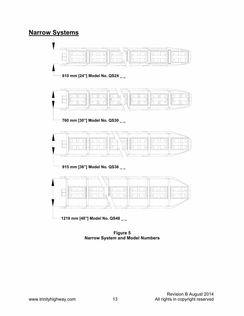
Narrow Systems
Figure 5 Narrow System and Model Numbers
1219 mm [48”] Model No. QS48 _ _
915 mm [36”] Model No. QS36 _ _
760 mm [30”] Model No. QS30 _ _
610 mm [24”] Model No. QS24 _ _

Revision B August 2014 www.trinityhighway.com 14 All rights in copyright reserved
Site Preparation/Foundation A QuadGuard® should be assembled only on an existing or freshly placed and cured concrete base (28 MPa [4000 psi] minimum). Location and orientation of the concrete base and attenuator must comply with project plans or as otherwise determined by the resident project engineer.
Recommended dimension and reinforcement specifications for new concrete foundations are provided in Trinity Highway concrete foundation drawings, supplied with the system. The system may be assembled on a non-reinforced concrete roadway (minimum 200 mm [8”] thick). Deployment cross-slope shall not exceed 8% and should not twist more than 2% over the length of the system; the foundation surface shall have a light broom finish.
Caution: Accurate placement of all steel rebar is critical to avoid interference with the concrete anchor bolts.
Warning: Location of the Backup in relation to nearby objects will affect the operation of the attenuator. Upon impact, the Fender Panels telescope rearward and extend beyond the rigid Backup as much as 876 mm [34.5”]. Position the Backup so that the rear ends of the last Fender Panels are a minimum of 760 mm [30”] forward of objects that would otherwise interfere with movement of the rearmost Fender Panels. Failure to comply with this requirement will result in impaired system performance offering motorists less protection and causing component damage.
Figure 6 Cross-Slope

Revision B August 2014 www.trinityhighway.com 15 All rights in copyright reserved
Assembly Procedures Inspect Shipping
Before deploying the QuadGuard® system, check the received parts against the shipping list supplied with the system. Make sure all parts have been received.
Assembly Procedures
Important: The Drawing Package supplied with the QuadGuard® system must be used with these instructions for proper assembly and should take precedence over these general instructions.
1) Determine Backup & Transition Type
The QuadGuard® system is available with a Tension Strut Backup or a Concrete Backup. See Figure 7 and 8, along with the Backup Assembly drawing, to determine which type of Backup is being deployed.
A Transition Panel or Side Panel must be used on each side of the Backup. A Side Panel is not needed when a Transition Panel is used. Several types of Transitions are available for use with the QuadGuard® system. See Figures 9 through 14 and the Drawing Package to determine which type of Panels to attach.
Figure 8 Concrete Backup
Figure 7 Tension Strut Backup
Figure 9 Transitioning the QuadGuard® System

Revision B August 2014 www.trinityhighway.com 16 All rights in copyright reserved
Transition Panel Types
Note: The proper Transition Panel or Side Panel must be used for proper impact performance of the system. The correct Panel(s) to use will depend on the direction of traffic and what type of barrier or roadside obstacle the QuadGuard® system is shielding. Contact the Customer Service Department prior to deployment if you have any questions.
Figure 14
Quad-Beam™ End Shoe Transition Panel
Figure 11 Quad-Beam™ to Safety Shape Barrier Transition Panel
Figure 10 No Transition
Figure 13 Quad-Beam™ to W-Beam Transition Panel
Figure 12 Quad-Beam™ to Thrie-Beam Transition Panel

Revision B August 2014 www.trinityhighway.com 17 All rights in copyright reserved
2) Mark System Location
Locate the centerline of the system by measuring the proper offset from the roadside obstacle. See the Drawing Package supplied with the system. Place chalk line to mark the centerline of the system. Mark a construction line parallel to the center line and offset 165 mm [6.5”] to one side as shown in Figure 15. The edge of the Monorail will be positioned on this line.
Note: The concrete foundation shall comply with the project plans supplied with the system.
Warning: Location of system with respect to the roadside obstacle is critical and dependent on the type of Transition Panel used. See the Project Plans supplied with the system for details.
Figure 15 (Top view of concrete foundation)
Revision B August 2014 www.trinityhighway.com 18 All rights in copyright reserved
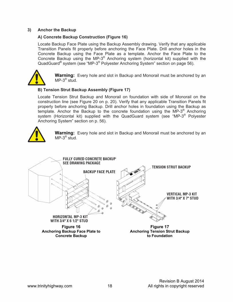
3) Anchor the Backup
A) Concrete Backup Construction (Figure 16)
Locate Backup Face Plate using the Backup Assembly drawing. Verify that any applicable Transition Panels fit properly before anchoring the Face Plate. Drill anchor holes in the Concrete Backup using the Face Plate as a template. Anchor the Face Plate to the Concrete Backup using the MP-3® Anchoring system (horizontal kit) supplied with the QuadGuard® system (see “MP-3® Polyester Anchoring System” section on page 56).
Warning: Every hole and slot in Backup and Monorail must be anchored by an MP-3® stud.
B) Tension Strut Backup Assembly (Figure 17)
Locate Tension Strut Backup and Monorail on foundation with side of Monorail on the construction line (see Figure 20 on p. 20). Verify that any applicable Transition Panels fit properly before anchoring Backup. Drill anchor holes in foundation using the Backup as template. Anchor the Backup to the concrete foundation using the MP-3® Anchoring system (Horizontal kit) supplied with the QuadGuard system (see “MP-3® Polyester Anchoring System” section on p. 56).
Warning: Every hole and slot in Backup and Monorail must be anchored by an MP-3® stud.
Figure 16 Anchoring Backup Face Plate to
Concrete Backup
Figure 17 Anchoring Tension Strut Backup
to Foundation

Revision B August 2014 www.trinityhighway.com 19 All rights in copyright reserved
4) Anchor the Monorail
A) Monorail Assembly for Concrete Backup (Figure 19)
Locate Monorail on foundation with side of Monorail on the construction line and rear edge of Monorail foot 10” forward of front face of Concrete Backup (see Figure 18).
Orient the Monorail so that the Monorail tongues face Backup (see Figure 18).
Drill 140 mm [5 1/2"] deep anchor holes using the Monorail as a template. Do not drill through foundation.
Warning: Every hole and slot in Backup and Monorail must be anchored by an MP-3® stud.
Anchor each Monorail section using the MP-3® vertical kits provided. See Figure 19 and the MP-3® Polyester Anchoring System Instructions included with this Manual. It is important to attach each segment of Monorail in alignment from the back to the front of the system (± 6 mm [1/4”]).
Warning: Improper alignment at the Monorail Sections will prevent proper system collapse during impact.
Figure 19 Proper Stud Height
Figure 18 Monorail Location for Concrete Backup
WASHER
ROADWAY BACKUP OR MONORAIL
NUT CAUTION:
40 MM [1.5”] MAXIMUM STUD HEIGHT
MP-3® Anchor

Revision B August 2014 www.trinityhighway.com 20 All rights in copyright reserved
B) Monorail Assembly for Tension Strut Backup (Figure 20)
Locate Monorail on foundation with side of Monorail on the construction line and rear edge of Backup foot 4” forward of edge of foundation (see Figure 20).
Drill 140 mm [5 1/2"] deep anchor holes using the Monorail as a template. Do not drill through foundation.
Warning: Every hole and slot in Backup and Monorail must be anchored by an MP-3® stud.
Anchor each Monorail section using the MP-3® vertical kits provided. See Detail 20a and the MP-3® Polyester Anchoring System Instructions included with this Manual. It is important to attach each segment of Monorail in alignment from the back to the front of the system (± 6 mm [1/4”]).
Warning: Improper alignment at the Monorail splice joints will prevent proper system collapse during impact.
Figure 20 Backup and Monorail Location for Tension Strut Backup
Detail 20a Proper Stud Height

Revision B August 2014 www.trinityhighway.com 21 All rights in copyright reserved
5) Attach Side Panels and/or Transition Panels to Backup Assembly
Attach Transition Panel or Side Panel to side of Backup using 5/8” rail bolt and 5/8” rail nut (two places - top and bottom holes only). See Figure 21 and Backup Assembly drawing.
Note: A Side Panel is not needed when a Transition Panel is used.
Assembly tip:
Use drift pin to align the center hole of the Panel with the center hole of the Backup before inserting the rail bolts.
Figure 21 Side Panel/Transition Panel Attachment
NARROW SIDE PANEL
Revision B August 2014 www.trinityhighway.com 22 All rights in copyright reserved
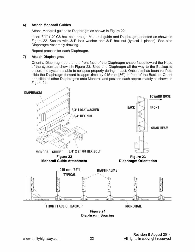
6) Attach Monorail Guides
Attach Monorail guides to Diaphragm as shown in Figure 22:
Insert 3/4" x 2” G8 hex bolt through Monorail guide and Diaphragm, oriented as shown in Figure 22. Secure with 3/4" lock washer and 3/4" hex nut (typical 4 places). See also Diaphragm Assembly drawing.
Repeat process for each Diaphragm.
7) Attach Diaphragms
Orient a Diaphragm so that the front face of the Diaphragm shape faces toward the Nose of the system as shown in Figure 23. Slide one Diaphragm all the way to the Backup to ensure the system is able to collapse properly during impact. Once this has been verified, slide the Diaphragm forward to approximately 915 mm [36”] in front of the Backup. Orient and slide all other Diaphragms onto Monorail and position each approximately as shown in Figure 24.
Figure 22 Monorail Guide Attachment
Figure 23 Diaphragm Orientation
Figure 24 Diaphragm Spacing

Revision B August 2014 www.trinityhighway.com 23 All rights in copyright reserved
8) Attach Fender Panels
Note: Do not mix the 5/8” rail nuts (large) with the 5/8” hex nuts (small) (see Figure 25).
Starting at the Backup, attach left and right Fender Panels shown on page 24 and Fender Panel Assembly drawing.
Step 1
Place the Fender Panel so that the center of the slot of the rearward Diaphragm is lined up with the approximate center of the slot in the Fender Panel.
Attach Mushroom Washer Assembly as shown in Figure 26 and Detail 26a and Detail 26b but do not torque at this time. (This helps to balance the Fender Panel.)
Step 2
Slide the Fender Panel forward until the holes in the Fender Panel line up with the holes in the forward Diaphragm.
Step 3
Use a drift pin to align the center hole of the Fender Panel with the center hole of the Diaphragm.
Step 4
Attach the front of the Fender Panels to the next Diaphragm using two (2) rail bolts and large hex rail nuts per side. Use only the top and bottom holes; leave the center hole open until the next Fender Panel is attached.
Figure 25 Rail Nuts are Oversize

Revision B August 2014 www.trinityhighway.com 24 All rights in copyright reserved
Step 5
Be sure Mushroom Washer lays flat against the Fender Panel as shown in Figure 26b. Standoff on Mushroom Washer must be seated completely through slot.
Figure 26 Fender Panel Assembly
Detail 26b Mushroom Washer Orientation
Detail 26a Mushroom Washer Attachment

Revision B August 2014 www.trinityhighway.com 25 All rights in copyright reserved
Step 6
Check Diaphragm spacing to ensure 915 mm [36”] between rear faces of consecutive Diaphragms as shown in Figure 27 and Fender Panel Assembly drawing.
Step 7
Once proper spacing has been achieved, torque the Mushroom Washer Assembly (small hex) nut until it reaches the end of the threads.
Assemble the remaining Diaphragms and Fender Panels following the same procedures.
Figure 27 Proper Spacing Between Diaphragms
Revision B August 2014 www.trinityhighway.com 26 All rights in copyright reserved
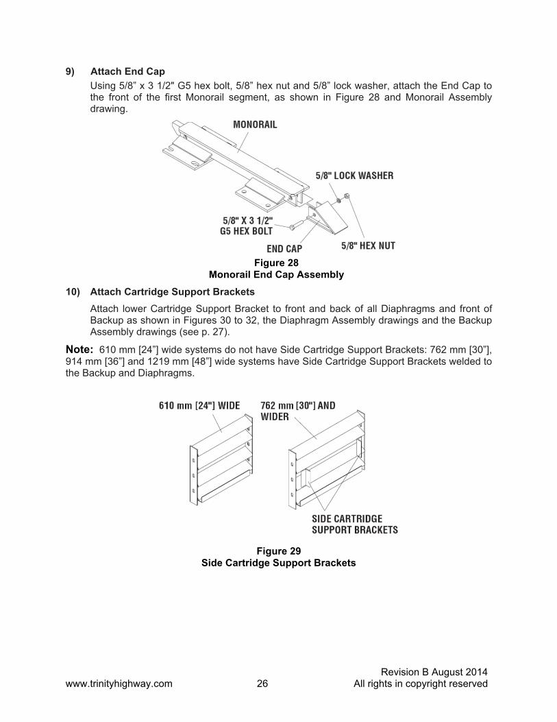
9) Attach End Cap
Using 5/8” x 3 1/2" G5 hex bolt, 5/8” hex nut and 5/8” lock washer, attach the End Cap to the front of the first Monorail segment, as shown in Figure 28 and Monorail Assembly drawing.
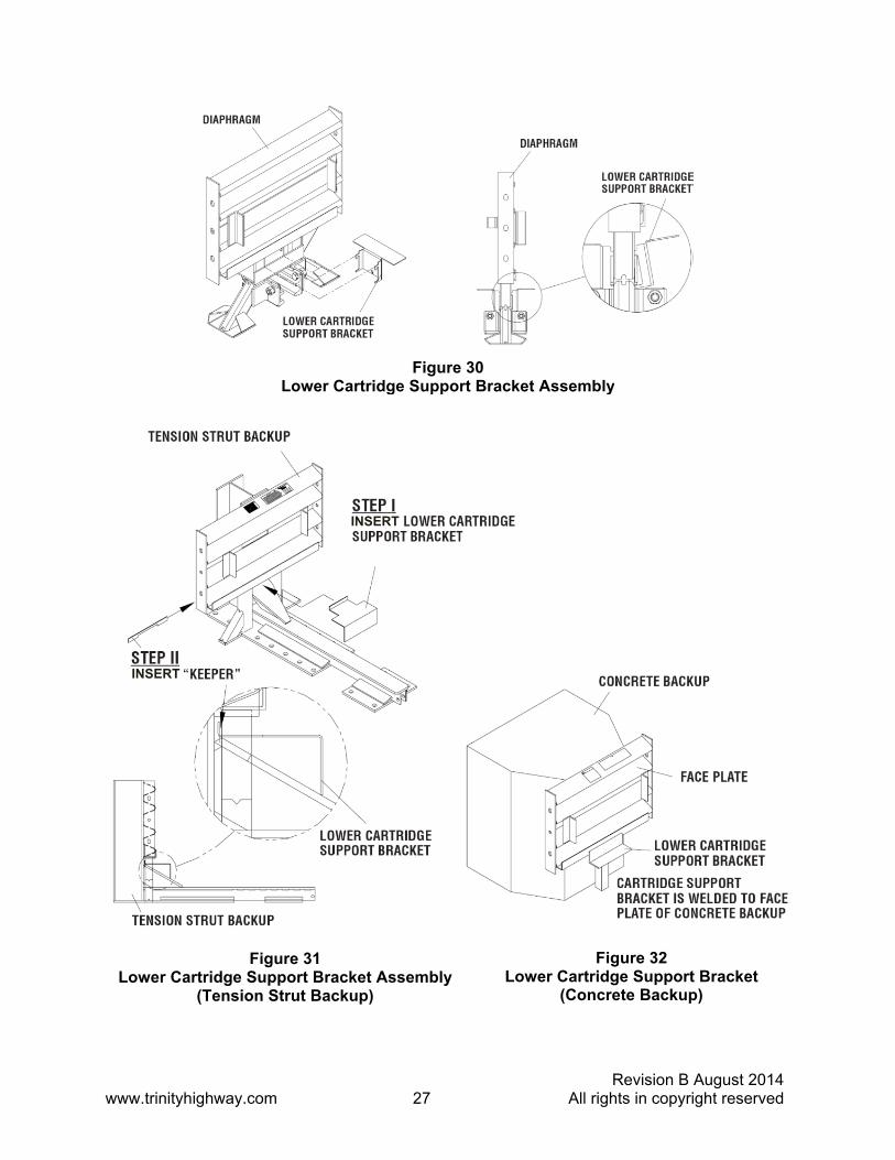
10) Attach Cartridge Support Brackets
Attach lower Cartridge Support Bracket to front and back of all Diaphragms and front of Backup as shown in Figures 30 to 32, the Diaphragm Assembly drawings and the Backup Assembly drawings (see p. 27).
Note: 610 mm [24”] wide systems do not have Side Cartridge Support Brackets: 762 mm [30”], 914 mm [36”] and 1219 mm [48”] wide systems have Side Cartridge Support Brackets welded to the Backup and Diaphragms.
Figure 28 Monorail End Cap Assembly
Figure 29 Side Cartridge Support Brackets
Revision B August 2014 www.trinityhighway.com 27 All rights in copyright reserved
Figure 31 Lower Cartridge Support Bracket Assembly
(Tension Strut Backup)
Figure 32 Lower Cartridge Support Bracket
(Concrete Backup)
INSERT
INSERT
Figure 30 Lower Cartridge Support Bracket Assembly

Revision B August 2014 www.trinityhighway.com 28 All rights in copyright reserved
11a) Attach Plastic Nose Assembly
Determine which style of Cartridges your system has. If your system has Cartridge style A as shown in Figure 33, attach Cartridge Support in the upper two slots as shown.
If your system has Cartridge style B as shown in Figure 33, attach Cartridge Support in the lower two slots as shown.
Figure 33 Adjustable Bracket Locations

Revision B August 2014 www.trinityhighway.com 29 All rights in copyright reserved
As shown in Detail 33a, Cartridge Style A is attached with the Adjustable Support Bracket incorrectly in the lower position.
As shown in Detail 33b, Cartridge Style B is attached with the Adjustable Cartridge Support Bracket incorrectly in the upper position.
Detail 33c shows the Adjustable Cartridge Support Bracket attached correctly.
Detail 33a Incorrect Attachment of Adjustable Cartridge Support Bracket
Detail 33b Incorrect Attachment of Adjustable Cartridge Support Bracket
Detail 33c Correct Attachment of Adjustable Cartridge Support Bracket

Revision B August 2014 www.trinityhighway.com 30 All rights in copyright reserved
Bolt the Nose Assembly directly to the Front Diaphragm, as shown in Detail 33d and the Nose Assembly drawings, using six (6) rail bolts which also hold the front two Fender Panels to the Diaphragm with Bar Washer under each bolt.
Place Pullout Brackets under center nuts.
The top and bottom holes of the Nose are slotted to provide adjustment. Adjust so the top edge of the Nose is level with the top edge of the Fender Panels and then torque all six (6) nuts to 35 N-m [25 ft-lb].
Detail 33e Adjust Nose
Detail 33d Nose Assembly
PULL OUT BRACKET

Revision B August 2014 www.trinityhighway.com 31 All rights in copyright reserved
11b) Optional Steel Nose Assembly
Bolt the Nose directly to the front Diaphragm, as shown in Figures 35, 35a, 35b and the Nose Assembly drawing, using six (6) rail bolts which also hold the front two Fender Panels to the Diaphragm with Bar Washer under each bolt.
Place Pullout Brackets under center bolts.
Figure 35
Detail 35a Detail 35b Steel Nose not shown for Clarity
SEE DETAILS 35a - 35g
STEEL NOSE ASSEMBLY
5/8” FLAT WASHER
5/8” X 1 1/4" HEX SOCKET BOLT 5/8” RAIL
NUT
PULLOUT BRACKET
SEE DETAIL 35C (INSIDE VIEW)
5/8” COUPLING NUT

Revision B August 2014 www.trinityhighway.com 32 All rights in copyright reserved
Detail 35f shows proper placement of Front Cartridge Support Bracket.
Detail 35g
Note difference of front Diaphragm Bracket. The Cartridge sits lower on this Bracket than the Bays to the rear.
Detail 35e Detail 35f Steel Nose not shown for Clarity
Detail 35d End View: Nose Cover Cut Away
Detail 35c End View with no Nose Cover
CARTRIDGE SUPPORT BRACKET
SEE DETAIL 35f TOTAL SIX 1/4-20 FASTENERS
113518G BOLT,HX,1/4X3/4,G5,G 118085G WASHER,LOCK,1/4,G 115946G NUT,HX,1/4,G
FASTEN ALL LOCATIONS WITH 1/4-20 FASTENERS
THREAD COUPLING NUT FLUSH WITH OUTSIDE HUMPS ON FENDER PANEL

Revision B August 2014 www.trinityhighway.com 33 All rights in copyright reserved
11c) Optional Belt Nose Assembly
a. Using 5/8” x 5” hex bolt, two (2) 5/8” x 1 3/4" flat washers and 5/8” hex nut, attach Fender Panel to front Diaphragm top and bottom as shown in Figure 36 (two places per side).
b. Using 5/8” x 5” hex bolt and 5/8” hex nut, attach Pullout Bracket to front Diaphragm and Fender Panel middle as shown (one place per side).
c. Thread second 5/8” nuts onto the attached bolts. Be sure the faces of the nuts are flush with humps on Fender Panels (see Figure 36). Slide third 5/8” x 1 3/4” flat washers onto bolts (three places per side).
d. Align holes in each end of the Nose Belt with the attached bolts (three per side) and slide Nose Belt onto bolts.
e. Align holes in Belt Clamps with bolts and slide Belt Clamps onto bolts.
f. Using fourth 5/8” x 1 3/4" flat washer and third 5/8” hex nut, secure the Belt Clamps and Nose Belt (three places per side).
Refer also to Nose Belt Assembly drawing.
Note: Nose alignment shown in Figure 33e not necessary with Nose Belt Assembly (see p. 30).
Note: Nose of system may be delineated to comply with local codes (chevron, reflective material, signs, etc. supplied by others).
5/8” X 1 3/4"FLAT WASHER
QG NOSE BELT
BELT CLAMP
5/8” X 5" G5 ALL THREAD HEX BOLT
5/8” X 1 3/4" FLAT WASHER
5/8” HEX NUT
FRONT DIAPHRAGM
FACE OF THE NUT TO BE FLUSH WITH HUMPS
ON FENDER PANEL
5/8” X 1 3/4" FLAT WASHER
5/8” HEX NUT
Figure 36 Optional Nose Belt Assembly

Revision B August 2014 www.trinityhighway.com 34 All rights in copyright reserved
12) Checking the System Assembly
At this point recheck to ensure that all fasteners are properly tightened throughout the system (anchor bolts, etc.). See warning below. Check all Fender Panels. If they do not fit tightly against the underlying Panel, system realignment may be necessary (see Detail 26a & 26b).
Warning: Bolt Torque Requirements
Anchor Studs – see Table A, p. 56 May slightly protrude above nuts
Critical Clearances Anchor Studs above nuts – see Figure 19, p. 19 Fender Panel Gap Narrow – 20 mm [0.78”] see below
13) Cartridge Assembly
Be sure the Adjustable Cartridge Support in the Nose is attached correctly. See “Attach Nose Assembly” in Step 11 on page 28. The top surface of the Nose Cartridge should be horizontal.
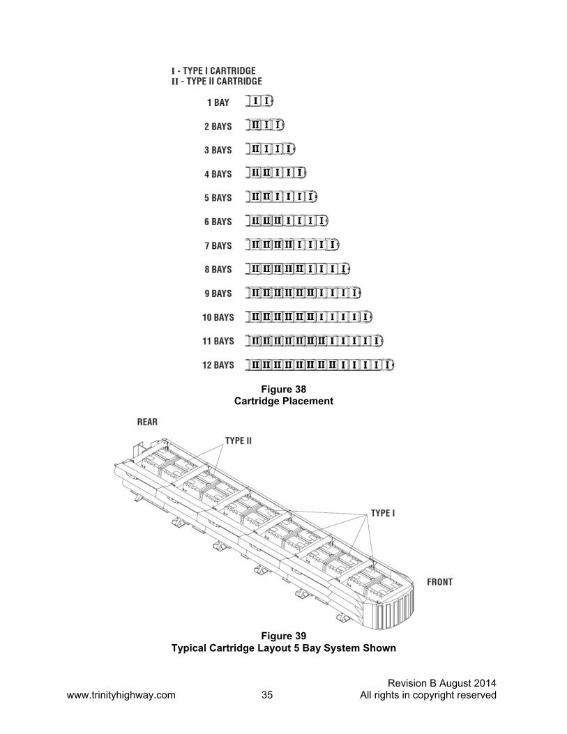
To complete the assembly of a QuadGuard® system, place the appropriate Cartridge in each Bay and Nose section of the system. Type 1 Cartridges are placed toward the front (Nose) of the system; Type II Cartridges are placed toward the rear (Backup) of the system (see Figures 38 and 39).
Warning: Placing the wrong Cartridge in the Nose or any Bay is strictly prohibited pursuant to NCHRP Report 350 testing criteria. Such configurations have not been accepted for use and may result in unacceptable crash performance.
Figure 37 Fender Panel Gap for Narrow Systems
Revision B August 2014 www.trinityhighway.com 35 All rights in copyright reserved
Figure 39 Typical Cartridge Layout 5 Bay System Shown
Figure 38 Cartridge Placement

Revision B August 2014 www.trinityhighway.com 36 All rights in copyright reserved
Wide Systems
Figure 40 Wide Systems and Model Numbers

Revision B August 2014 www.trinityhighway.com 37 All rights in copyright reserved
Site Preparation/Foundation A QuadGuard® system should be constructed only on an existing or freshly placed and cured concrete base (28 MPa [4000 psi] minimum). Location and orientation of the concrete base and attenuator must comply with project plans or as otherwise determined by the resident project engineer.
Recommended dimension and reinforcement specifications for new concrete foundations are provided in Trinity Highway concrete foundation drawings, supplied with the system. The system may be assembled on a non-reinforced concrete roadway (minimum 200 mm [8”] thick). Deployment cross-slope shall not exceed 8% and should not twist more than 2% over the length of the system; the foundation surface shall have a light broom finish.
Caution: Accurate placement of all steel rebar is critical to avoid interference with the concrete anchor bolts.
Warning: Location of the Backup in relation to nearby objects will affect the operation of the attenuator. Upon impact, the Fender Panels telescope rearward and extend beyond the rigid Backup as much as 876 mm [34.5”]. Position the Backup so that the rear ends of the last Fender Panels are a minimum of 760 mm [30”] forward of objects that would otherwise interfere with movement of the rearmost Fender Panels. Failure to comply with this requirement will result in impaired system performance offering motorists less protection and cause component damage.
Inspect Shipping
Before deploying the QuadGuard® system, check the received parts against the shipping list supplied with the system. Make sure all the parts have been received.
Assembly Procedures
Caution: The Drawing Package supplied with the QuadGuard® system must be used with these instructions for proper assembly and should take precedence over these general instructions.
1) Determine Backup and Transition Type
The QuadGuard® is available with a Tension Strut Backup or a Concrete Backup. See Figures 41 and 42, along with the Backup assembly drawing, to determine which type of Backup is being deployed.
A Transition Panel or Side Panel must be used on each side of the Backup. A Side Panel is not needed when a Transition Panel is used. Several types of transitions are available for use with the QuadGuard® system. See Figures 43 through 48 and the drawing package to determine which types of panels to attach.

Revision B August 2014 www.trinityhighway.com 38 All rights in copyright reserved
Figure 41 Tension Strut Backup
Figure 42 Concrete Backup
Figure 43 Transitioning the QuadGuard® System

Revision B August 2014 www.trinityhighway.com 39 All rights in copyright reserved
Transition Panel Types
Note: The proper Transition Panel or Side Panel must be used for impact performance of the system. The correct Panel(s) to use will depend on the direction of traffic and what type of barrier or roadside feature the QuadGuard® system is shielding. Contact the Customer Service Department prior to deployment if you have any questions. Arrows indicate traffic direction.
Figure 44 No Transition
Figure 45 Quad-Beam™ to Safety Shape Barrier
Figure 47 Quad-Beam™ to W-Beam
Figure 46 Quad-Beam™ to Thrie-Beam
Figure 48 Quad-Beam™ End Shoe
Note: Arrows indicate traffic direction.
Note: Arrows indicate traffic direction.

Revision B August 2014 www.trinityhighway.com 40 All rights in copyright reserved
2) Mark System Location
Locate the centerline of the system by measuring the proper offset from the roadside obstacle. See the Drawing Package supplied with the system. Place chalk line to mark the centerline of the system. Mark a construction line parallel to the center line and offset 165 mm [6.5”] to one side as shown in Figure 49. The edge of the Monorail will be placed on this line.
Note: The concrete foundation shall comply with the project plans supplied with the system.
Warning: Location of system with respect to the roadside obstacle is critical and dependent on the type of Transition Panel used. See the Project Plans supplied with the system for details.
3) Anchor the Backup
A) Concrete Backup Construction (Figure 50)
Locate Backup Face Plate using the Backup assembly drawing. Verify that any applicable Transition Panels fit properly before anchoring the Face Plate. Drill anchor holes in the Concrete Backup using the Face Plate as a template. Anchor the Face Plate to the Concrete Backup using the MP-3® Anchoring system (horizontal kit) supplied with the QuadGuard® system (see “MP-3® Polyester Anchoring System” section on p. 56).
Warning: Every hole and slot in Backup and Monorail must be anchored by an MP-3® stud.
Figure 49 (Top view of concrete foundation)
Figure 50 Anchoring Backup Face Plate to Concrete Backup

Revision B August 2014 www.trinityhighway.com 41 All rights in copyright reserved
B) Monorail Assembly for Tension Strut Backup
Locate the Tension Strut Backup on foundation with side of Monorail on the construction line (see Figure 55 on page 44). Verify that any applicable Transition Panels fit properly before anchoring Backup. Drill anchor holes in foundation using the Backup as template. Anchor the Backup to the concrete foundation using the MP-3® Anchoring System (vertical kit) supplied with the QuadGuard® system (see “MP-3® Polyester Anchoring System” section on p. 56).
Warning: Every hole and slot in Backup and Monorail must be anchored by an MP-3® stud.
Figure 51 Anchoring Tension Strut Backup to Foundation

Revision B August 2014 www.trinityhighway.com 42 All rights in copyright reserved
C) Extra-Wide Tension Strut Backup Assembly (Figure 52)
Locate the Extra-Wide Tension Strut Backup center section and Monorail on foundation with side of Monorail on the construction line (see Figure 55 on p.44).
Locate the Extra-Wide Tension Strut Backup left section on the left side of the center section, aligning the three holes in the side plates.
Locate the Extra-Wide Tension Strut Backup right section on the right side of the center section, aligning the three holes in the side plates.
Secure the Backup sections to each other using 5/8” x 2” hex bolt, 5/8” x 1 3/4" flat washer (2), 5/8” lock washer and 5/8” hex nut (6 places) as shown in Figure 52 and Detail 52a.
Verify that any applicable Transition Panels fit properly before anchoring Backup. Drill anchor holes in foundation using the Backup as template. Anchor the Backup to the foundation using the MP-3® vertical kits supplied with the QuadGuard® system (see “MP-3® Polyester Anchoring System” on page 56).
Warning: Every hole and slot in Backup and Monorail must be anchored by an MP-3® stud.
Detail 52a
Figure 52 Anchoring Extra-Wide Tension Strut Backup to
Foundation See Drawing Package
52a
Revision B August 2014 www.trinityhighway.com 43 All rights in copyright reserved
4) Anchor the Monorail
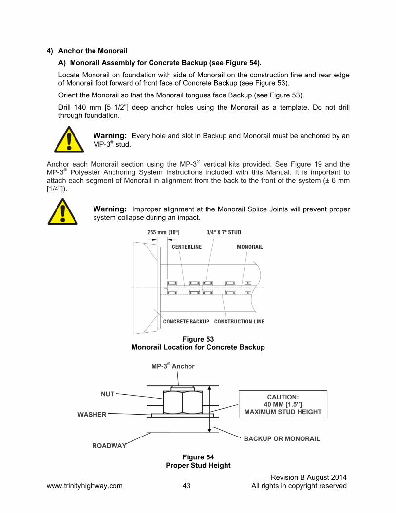
A) Monorail Assembly for Concrete Backup (see Figure 54).
Locate Monorail on foundation with side of Monorail on the construction line and rear edge of Monorail foot forward of front face of Concrete Backup (see Figure 53).
Orient the Monorail so that the Monorail tongues face Backup (see Figure 53).
Drill 140 mm [5 1/2"] deep anchor holes using the Monorail as a template. Do not drill through foundation.
Warning: Every hole and slot in Backup and Monorail must be anchored by an MP-3® stud.
Anchor each Monorail section using the MP-3® vertical kits provided. See Figure 19 and the MP-3® Polyester Anchoring System Instructions included with this Manual. It is important to attach each segment of Monorail in alignment from the back to the front of the system (± 6 mm [1/4”]).
Warning: Improper alignment at the Monorail Splice Joints will prevent proper system collapse during an impact.
Figure 54 Proper Stud Height
Figure 53 Monorail Location for Concrete Backup
MP-3® Anchor
WASHER
ROADWAY BACKUP OR MONORAIL
NUT CAUTION: 40 MM [1.5”]
MAXIMUM STUD HEIGHT

Revision B August 2014 www.trinityhighway.com 44 All rights in copyright reserved
B) Monorail Assembly for Tension Strut Backup (see Figure 55).
Locate Monorail on foundation with side of Monorail on the construction line and rear edge of Backup foot 4” forward of edge of foundation (see Figure 55).
Drill 140 mm [5 1/2"] deep anchor holes using the Monorail as a template. Do not drill through foundation.
Warning: Every hole and slot in Backup and Monorail must be anchored by an MP-3® stud.
5) Attach Side Panels and/or Transition Panels to Backup Assembly (see Figure 56).
a. Attach Hinge Plate to the Transition Panel or Side Panel using 5/8” rail bolt and 5/8” rail nut (two places – top and bottom holes only).
b. Attach Transition Panel or Side Panel assembly to side of Backup using 5/8” x 4” hex bolt, 5/8” lock washer and 5/8” hex nut at three places on each side of Backup (see Figure 56).
c. Attach diagonal brace to Fender Panel and Backup using 3/8” hex bolt, 3/8” lock washer and 3/8” hex nut (two places per brace: 4 places per side).
d. Secure each diagonal brace with 3/8” hex bolt, 3/8” lock washer, and 3/8” hex nut (two places per brace) as shown in Figure 56.
Note: A Side Panel is not needed when a Transition Panel is used. Diagonal braces not used with some Transition Panels. See drawing package.
TONGUE
Detail 55a Proper Stud Height
Figure 55 Backup and Monorail Location for Tension Strut Backup

Revision B August 2014 www.trinityhighway.com 45 All rights in copyright reserved
Assembly tip:
Use drift pin to align the center hole of the Panel with the center hole of the Backup before attaching the rail bolts.
Figure 56 Side Panel/Transition Panel Attachment
TENSION STRUT BACKUP
3/8” X 3 1/2" HEX BOLT
3/8” LOCK WASHER
CONCRETE BACKUP
5/8” RAIL NUT (LARGE) (SEE FIGURE 60)
5/8” LOCK WASHER
3/8” HEX NUT
DIAGONAL BRACE (OUTER)
3/8” X 3 1/2" HEX BOLT
5/8” X 4" HEX BOLT
DIAGONAL BRACE (INNER)
HINGE PLATE
5/8” HEX NUT (SMALL)
3/8” LOCK WASHER
5/8” RAIL BOLT
WIDE SIDE PANEL
3/8” HEX NUT

Revision B August 2014 www.trinityhighway.com 46 All rights in copyright reserved
6) Attach Monorail Guides
Attach Monorail guides to Diaphragm as shown in Figure57:
Insert 3/4" x 2” G8 hex bolt through Monorail guide and Diaphragm, oriented as shown in Figure 57. Secure with 3/4" lock washer and 3/4" hex nut (typical two places per guide). See also Diaphragm assembly drawing. Shims are sandwiched between Monorail guides and Diaphragm.
Repeat process for each Diaphragm.
Figure 57 Monorail Guide Attachment
3/4" HEX NUT
3/4" LOCK WASHER
3/4" X 2” GR8 HEX BOLT
MONORAIL GUIDE
DIAPHRAGM
Revision B August 2014 www.trinityhighway.com 47 All rights in copyright reserved
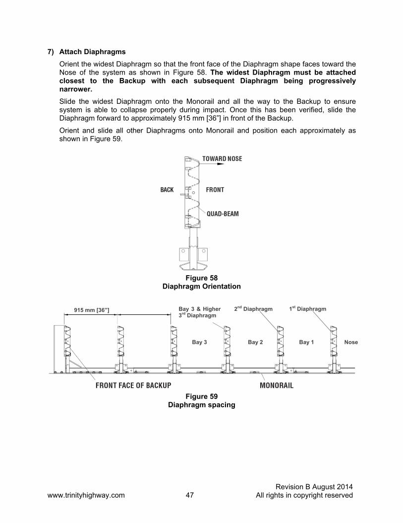
7) Attach Diaphragms
Orient the widest Diaphragm so that the front face of the Diaphragm shape faces toward the Nose of the system as shown in Figure 58. The widest Diaphragm must be attached closest to the Backup with each subsequent Diaphragm being progressively narrower.
Slide the widest Diaphragm onto the Monorail and all the way to the Backup to ensure system is able to collapse properly during impact. Once this has been verified, slide the Diaphragm forward to approximately 915 mm [36”] in front of the Backup.
Orient and slide all other Diaphragms onto Monorail and position each approximately as shown in Figure 59.
Figure 58 Diaphragm Orientation
915 mm [36”] Bay 3 & Higher 3rd Diaphragm
Bay 2Bay 3 Bay 1 Nose
2nd Diaphragm 1st Diaphragm
Figure 59 Diaphragm spacing

Revision B August 2014 www.trinityhighway.com 48 All rights in copyright reserved
8) Attach Hinge Plate onto Fender Panels
Note: Do not mix the 5/8” rail nuts (large) with the 5/8” hex nuts (small) (see Figure 60).
Note: For proper impact performance, wide systems must use Hinge Plates.
Attach Hinge Plate on each Fender Panel using two (2) 5/8” rail bolts and two (2) 5/8” rail nuts, using top and bottom holes only, leaving the center-hole open as shown in Figure 61.
9) Attach Fender Panels
Starting at the Backup, attach left and right Fender Panels as shown in Figure 62 and Fender Panel Assembly drawing.
Step 1
Place the Fender Panel so that the center of the slot of the rearward Diaphragm is lined up with the approximate center of the slot in the Fender Panel.
Attach Mushroom Washer Assembly as shown in Figure 62, Detail 62a and Detail 62b, but do not torque at this time (this helps to balance the Fender Panel).
Figure 60 Rail Nuts are Oversize
Figure 61 Hinge Plate Assembly

Revision B August 2014 www.trinityhighway.com 49 All rights in copyright reserved
Step 2
Slide the Fender Panel forward until the holes in the Fender Panel line up with the holes in the forward Diaphragm.
Step 3
Use a drift pin to align the center hole of the Fender Panel with the center hole of the Diaphragm.
Step 4
Attach the front of the Fender Panels to the next Diaphragm using two (2) rail bolts and large hex nuts per side. Use only the top and bottom holes; leave the center hole open until the next Fender Panel is attached.
Step 5
Be sure Mushroom Washer lays flat against the Fender Panel as shown in Detail 62a. Standoff on Mushroom Washer must be seated completely through slot.
Figure 62 Fender Panel Assembly

Revision B August 2014 www.trinityhighway.com 50 All rights in copyright reserved
Detail 62a Mushroom Washer Orientation
Detail 62b Mushroom Washer Attachment
DIAPHRAGM OR BACKUP
18 mm [11/16]” ROUND HOLE
LONG SLOT IN FENDER PANEL
MUSHROOM WASHER
QUAD-BEAM FENDER PANEL
HINGE PLATE
PANEL ALREADY ATTACHED TO DIAPHRAGM OR BACKUP
1 1/2" DIE SPRING
5/8" RAIL NUT (LARGE)

Revision B August 2014 www.trinityhighway.com 51 All rights in copyright reserved
Step 6
Check Diaphragm spacing to ensure 915 mm [36”] between rear faces of consecutive Diaphragms as shown in Figure 63 and Fender Panel Assembly drawing.
Step 7
Once the proper spacing has been achieved, torque the Mushroom Washer Assembly (small hex nut) until it reaches the end of the threads. Assemble the remaining Diaphragms and Fender Panels following the same procedures.
10) Attach End Cap
Using 5/8” x 3 1/2” G5 hex bolt, 5/8” hex nut and 5/8” lock washer, attach the End Cap to the front of the first Monorail segment as shown in Figure 64 and the Monorail Assembly drawing.
Figure 64 Monorail End Cap Assembly
Figure 63 Proper Spacing Between Diaphragms
DIAPHRAGM OR BACKUP
FENDER PANELDIAPHRAGM
BAY SPACING
915 mm [36”]
Revision B August 2014 www.trinityhighway.com 52 All rights in copyright reserved
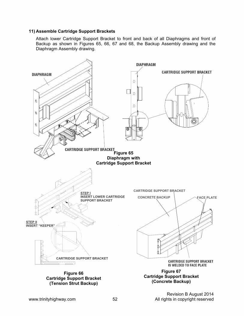
11) Assemble Cartridge Support Brackets
Attach lower Cartridge Support Bracket to front and back of all Diaphragms and front of Backup as shown in Figures 65, 66, 67 and 68, the Backup Assembly drawing and the Diaphragm Assembly drawing.
Figure 66 Cartridge Support Bracket
(Tension Strut Backup)
Figure 67 Cartridge Support Bracket
(Concrete Backup)
Figure 65 Diaphragm with
Cartridge Support Bracket
CONCRETE BACKUP
CARTRIDGE SUPPORT BRACKET
FACE PLATE
CARTRIDGE SUPPORT BRACKET
STEP II INSERT “KEEPER”
STEP I INSERT LOWER CARTRIDGE SUPPORT BRACKET

Revision B August 2014 www.trinityhighway.com 53 All rights in copyright reserved
12) Attach Nose Assembly
See pages 28 – 33 for Nose Assembly information.
13) Checking the System Assembly
At this point recheck to ensure that all fasteners are properly tightened throughout the system (anchor bolts, etc.). See warning below. Check all Fender Panels. If they do not fit tightly against the underlying Fender Panels, system realignment may be necessary (see Figure 69).
Warning: Bolt Torque Requirements
Anchor Studs – see Table A, p. 56 May slightly protrude above nuts
Critical Clearances Anchor Studs above nuts – see Figure 18, p. 19 Fender Panel Gap Wide – 25 mm [1.00”] see below
Figure 69 Fender Panel Gap for Wide Systems
Figure 68 Extra-Wide First Diaphragm With Cartridge Support Bracket
(see Drawing Package)

Revision B August 2014 www.trinityhighway.com 54 All rights in copyright reserved
14) Cartridge Attachment
Be sure the Adjustable Cartridge Support in the Nose is attached correctly. See “Attach Nose Assembly” in Step 11a on page 28. The top surface of the Nose Cartridge should be horizontal.
To complete the assembly of a QuadGuard® system, place the appropriate Cartridge in each Bay and Nose section of the system. Type I Cartridges are placed toward the front (Nose) of the system; Type II Cartridges are placed toward the rear (Backup) of the system (see Figures 70 and 71).
Warning: Placing the wrong Cartridge in the Nose or any Bay is strictly prohibited pursuant to NCHRP Report 350 testing criteria. Such configurations have not been accepted for use and may result in unacceptable crash performance.
Figure 70
Cartridge Placement

Revision B August 2014 www.trinityhighway.com 55 All rights in copyright reserved
Figure 71
Typical Cartridge Layout (6 Bay System Shown)

Revision B August 2014 www.trinityhighway.com 56 All rights in copyright reserved
MP-3® Polyester Anchoring system The MP-3® Polyester Anchoring System is a quick and easy way to securely anchor crash cushions and other common highway devices. MP-3® features high pullout strength, superior vibration resistance, and exceptional durability.
Each MP-3® kit contains a can of MP-3® resin, hardener, cold weather promoter, studs, nuts, and washers. The cold weather promoter shortens hardening time by as much as seven hours. Both vertical and horizontal assemblies are possible using the MP-3® system.
Vertical Assemblies
Note: Read MP-3® Instructions before starting.
1) Prepare the Concrete Foundation
Warning: Do not allow the MP-3® resin or hardener to contact skin or eyes. See MSDS (material safety data sheet) supplied with the MP-3® kit for first-aid procedures. Use only in well-ventilated area. Do not use near open flame.
Warning: Wear safety goggles, apron, and gloves during construction.
The anchor bolts (studs) that anchor the QuadGuard® system Backup and/or Monorail sections to the concrete foundation must be those shipped in the kit or of high strength steel (830 MPa [120,000 psi] minimum tensile strength or equal). These studs must be set in minimum 28 MPa [4000 psi] concrete. Allow the concrete to cure a minimum of seven days before applying MP-3®.
2) Drill Holes
Note: Trinity Highway recommends using double-fluted drill bits to achieve optimum tensile strength when applying the MP-3® anchoring system.
Use the part that is to be anchored as a drilling template. Drill the holes 3 mm [1/8”] larger than the stud diameter to the recommended depth, using a rotary hammer drill. If a diamond drill bit is used, the surface will be too smooth for the MP-3® to adhere and full strength will not be achieved. See the MP-3® assembly instructions provided with your kit. Check to be sure all the holes are drilled to the proper depth and aligned with the part to be anchored (see Table A).
Stud Size
Concrete Bit Size
Minimum Depth
Recommended Torque
3/4”x 6 1/2" 22 mm [7/8”] 125 mm [5”] 165 N-m [120 ft-lb] 3/4”x 7" 22 mm [7/8”] 140 mm [5” 1/2"] 165 N-m [120 ft-lb] 3/4”x 18" 22 mm [7/8”] 420 mm [16 1/2”] 15 N-m [10 ft-lb]
Important: When mounting on asphalt, initial torque shall be as shown in Table A. Due to the instability of asphalt, anchors may loosen over time. For this reason Trinity Highway recommends anchoring to asphalt only at temporary locations. It is recommended to re-torque anchors in asphalt every 6 months to the proper initial torque specified.
Table A MP-3® Anchoring Information

Revision B August 2014 www.trinityhighway.com 57 All rights in copyright reserved
3) Clean the Holes
Blow the concrete dust from the hole using oil-free compressed air. Thoroughly brush it with a stiff-bristled brush and then blow it out again. If the hole is wet, completely flush it with water while brushing. Then blow it clean using oil-free compressed air.
4) Mix the Resin and Hardener
Wearing gloves, apron and safety goggles, remove the lids from the MP-3® Part A-resin and Part B-hardener containers. Pour Part B into Part A then mix vigorously for 30 seconds to form MP-3® grout (an anchor stud may serve as a stirring rod).
5) Add Cold Weather Promoter (in Cold Weather)
For faster hardening in cold weather, promoter may be used. Add the entire contents of the partially filled promoter container to the MP-3® grout then mix for an additional 30 seconds. Use immediately because the MP-3® grout will thicken quickly (see Table B for hardening times).
Warning: Do not use promoter when the temperature is above 15 degrees Celsius (60 degrees Fahrenheit) as the grout will harden too quickly. Use only in well-ventilated area. Do not use near open flame.
6) Pour Grout into Holes
Crimp the mouth of the can to form a sprout and pour the MP-3® grout mixture down into the hole through the part. Fill the hole to 1/3 - 1/2 full.
Caution: Do not overfill or underfill the hole. If the hole is overfilled, there will not be enough grout to use all of the anchor studs/kit. If hole is underfilled, the grout may not develop the required pull out strength.
7) Add the Washers and Nuts
Place a flat washer onto the stud and then thread a nut on until 1 or 2 threads of the NUT are left exposed.
8) Insert Studs in Holes and Wait for Grout to Harden
Push the stud down through the part to be anchored and into the hole. Give the stud several twists in the MP-3® to wet the threads.
Caution: Do not disturb or load the stud until the MP-3® material has hardened (see Table B).
9) Torque the Nuts
Once the grout has hardened, torque the nut to the recommended values (see Table A on p. 56).

Revision B August 2014 www.trinityhighway.com 58 All rights in copyright reserved
Temperature Hardening Times (hours) (C) (F) No Promoter With Promoter >26 >80 1/2 N/R*
22-26 70-79 1 N/R 16-21 60-69 2 N/R 10-15 50-59 4 3/4
4-9 40-49 8 1 -1-3 30-39 N/R 1 1/2 <-1 <30 N/R N/R**
*Not recommended **Contact Customer Service Department for moreInformation (see p. 3).
Horizontal Assemblies The horizontal MP-3® kit is the same as the vertical kit except that a Cartridge for a standard caulking gun is supplied in the horizontal kits and the resin for the horizontal kits is a thixotropic (TX) resin. The TX-Resin is a gelled resin intended to keep the grout in place in horizontal holes during application.
When using the horizontal MP-3® kits, follow the vertical instructions with the following exceptions:
1) Thread Dispensing Tip onto Dispenser
Prior to mixing the grout, carefully thread the dispensing tip onto the dispenser.
2) Pour Mixed Grout into Dispenser
Once the grout is mixed, crimp the mouth of the can to form a spout and pour the MP-3® grout into the open end of the dispenser (use mixing stud to scrape out the portion remaining in the can). You may use the box to hold the dispenser upright. Close the box lid and poke the dispenser tip into the top of it. Seal the dispenser with the plunger provided.
3) Place Dispenser in Caulking Gun and Dispense Grout
Cut the small end of the dispenser tip off. Place the dispenser into a caulking gun and dispense until MP-3® TX grout reaches the tip of the dispenser, then release pressure. Push the dispenser tip through the part to the bottom of the hole and dispense while slowly withdrawing the tip.
Caution: Do not overfill or underfill the hole. Fill hole approximately 1/3 to 1/2 full. If the hole is overfilled, there will not be enough grout to use all of the anchor studs/kit. If hole is underfilled, the grout may not develop the required pull out strength.
4) Add the Washers and Nuts
Put washer and nut on stud leaving nut flush with end of stud (see Figure 72).
Table B Approximate Hardening Times (hours)

Revision B August 2014 www.trinityhighway.com 59 All rights in copyright reserved
5) Insert Studs into Holes
Push stud through part to be anchored and into hole. Twist the stud in the MP-3® grout to wet the threads.
Note: In horizontal applications the stud should be flush with the top of the nut (see Figure 72).
Caution: Do not disturb or load the stud until the MP-3® material has hardened (see Table B for hardening times).
6) Torque the nuts
Once the grout has hardened, torque the nut to 165 N-m [120 ft-lb].
MP-3® Assembly Cautions 1) Shelf life
If the shelf life of the MP-3® has expired (see MP-3® kit for expiration information), mix a small amount of MP-3® in the proportions of one part A to two parts B by volume. If the material does not set according to the instructions, replace MP-3® kit with new material.
Warning: Do not use the MP-3® if: the material fails to set up, Part A-Resin had gelled (for vertical applications), or TX-Resin is NOT gelled (for horizontal applications).
2) Steel rebar
If steel rebar is encountered while drilling an MP-3® anchor bolt hole, apply one of the following solutions:
A) Using a diamond core drill bit or rebar drilling tool, drill through the rebar only, then switch back to the concrete bit and drill into the underlying concrete until the proper hole depth is reached.
Caution: Do not drill through rebar without first obtaining permission to do so from the local project engineer.
B) Drill a new hole down at an angle past the rebar to the proper depth. Anchor the stud by completely filling both holes with MP-3®.
Figure 72 MP-3® Horizontal Application

Revision B August 2014 www.trinityhighway.com 60 All rights in copyright reserved
Maintenance and Repair
Inspection Frequency Inspections are recommended as needed based upon volume of traffic and impact history. Visual Drive-By Inspections are recommended at least once a month. Walk-Up Inspections are recommended at least once a year for QuadGuard® systems on asphalt.
Visual Drive-By Inspection 1) Check to see if there is evidence of an impact. If so, a walk-up inspection will be
necessary.
2) Check to see if the Cartridges appear to be off the Support Brackets. Any damaged Cartridges will need to be replaced.
Warning: See Cartridge placement instructions on page 35 or 54.
3) Be sure the Nose is in place.
4) Note the location and condition of the QuadGuard® system and the date of visual drive-by inspection.
Walk-Up Inspection 1) Clear and dispose of any debris on the site.
2) Be sure all bolts are tight and rust free.
3) Be sure anchor bolts are securely anchored (see Table A on p. 56).
4) Be sure Diaphragm Legs are straight.
5) Be sure all Mushroom Washer Assemblies are properly aligned and positioned.
6) Fender Panels and Transition Panels should nest tightly against the system.
Warning: Fender Panel Maximum gap allowed:Narrow Systems 20 mm [0.78”] Wide Systems 25 mm [1.00”]
(see Figures 76 & 77 on p. 63)
7) Be sure Cartridges have not been damaged and are properly positioned on their Support Brackets. Replace crushed or sagging Cartridges. To ensure NCHRP Report 350 criteria, partially crushed Cartridges (due to slow speed impacts) shall be replaced.
8) Make all necessary repairs as described above. See Post-Impact Instructions on page 61 for more information.
9) Note the location and condition of the QuadGuard® system and any work done in the Impact Attenuator Inspection Logbook under the date of this inspection. If further repair is necessary, note repair request date in logbook. See Post-Impact Instructions on page 61 and the assembly section of this Manual for more information.
10) In deciding if a product should be replaced, or is potentially reusable, a trained engineer, experienced in highway products, directed by the DOT, or other appropriate local highway authority, must be consulted.

Revision B August 2014 www.trinityhighway.com 61 All rights in copyright reserved
Post-Impact Instructions Danger: If either (wide or narrow) system is anchored to asphalt, up to 10% of the total anchors may be replaced if damaged. If more than 10% of the anchors are damaged, the system should be relocated to fresh, undisturbed asphalt and redeployed using the 460 mm [18”] threaded rods.
Narrow Systems
1) Deploy the appropriate traffic-control devices for protection.
2) Check to see that all anchor bolts have remained firmly anchored in the roadway surface. Replace any that are loose, broken, or pulled out.
The proper performance of the system during an angle impact depends on the Monorail anchors being properly anchored.
3) Clear and dispose of any debris on the site.
4) Check the system to be certain that the Mushroom Washer Assemblies holding the Fender Panels together are still intact and that the system has not been deformed in a way that would prevent pulling it back to its original position.
5) Be sure that the Diaphragm Support Legs are all properly attached to the Monorail.
Wide Systems
1) Deploy the appropriate traffic-control devices for protection.
2) Check to see that all anchor bolts have remained firmly anchored in the roadway surface. Replace any that are loose, broken, or pulled out.
The proper performance of the system during an angle impact depends on the Monorail Anchors being properly anchored.
Caution: QuadGuard® wide systems should never be anchored to asphalt.
3) Clear and dispose of any debris on the site.
4) Check the system to be certain that the Mushroom Washer Assemblies holding the Fender Panels together are still intact and that the system has not been deformed in a way that would prevent pulling it back to its original position.
5) Be sure that the Diaphragm Support Legs are all properly attached to the Monorail.
Caution: Use safety goggles and gloves when refurbishing the Mushroom Spring Assembly. Do not place fingers underneath an assembled Mushroom Washer. Parts may suddenly shift and fingers may be pinched. If the spring is still under compression as the nut is nearing the end of the bolt, to prevent injury, make sure that the spring is restrained with a clamp so it does not suddenly release when nut is removed from the Mushroom Washer Bolt.
6) Attach chain to Pullout Brackets on first Diaphragm (see Figure 73). Attach both ends of chain to a heavy vehicle (such as a 1 ton pickup).

Revision B August 2014 www.trinityhighway.com 62 All rights in copyright reserved
Warning: Stand clear in case chain breaks or becomes disconnected.
Slowly pull the QuadGuard® system forward until the system reaches its original length. Have someone watch the system during repositioning to be certain previously undetected damage does not cause the Diaphragms to bind or pull out improperly.
7) Remove all crushed Cartridges from within the system.
8) Check to see that the Diaphragms are in usable condition. Diaphragms which are bowed or have bent legs must be replaced.
9) Check that the Fender Panels are properly attached with the Mushroom Washer Assemblies. Damaged Fender Panels and Transition Panels must be replaced. Often, Cartridge Support Brackets with minor damage can be straightened and reused by doing the following:
a. Remove damaged Cartridge Support Bracket from Diaphragm.
b. Clamp Cartridge Support Bracket to Backup and begin bending using pipe wrench as shown in Figure 74.
Figure 73 Pullout
Figure 74 Straighten Cartridge Support Bracket

Revision B August 2014 www.trinityhighway.com 63 All rights in copyright reserved
c. Then, using a sledge hammer and Quad-Beam™ Panel on Backup as an anvil, straighten Cartridge Support Bracket back into 90° shape (see Figure 75).
Warning: Fender Panel Maximum gap allowed:Narrow Systems 20 mm [0.78”] Wide Systems 25 mm [1.00”]
10) Check the gaps between Fender Panels. The maximum gap allowed for these overlapping parts (including Fender Panels overlapping Panels behind the system) is 20 mm [.78”] for narrow systems and 25 mm [1.00”] for wide systems. Be sure the Mushroom Washer Assemblies are torqued to the end of the threads. If the gaps between the Fender Panels are still too large, it may be necessary to replace bent parts.
11) Replace all crushed Cartridges (see Cartridge Placement on p. 35 or 54).
12) Remove damaged Nose Assembly. Attach the new Nose to the first Diaphragm using the six (6) rail bolts, coupling nuts, rail nuts, cap screws, Pull-Out Brackets, and Bar Washers that hold the Nose to the first Diaphragm. Adjust Nose to align with Fender Panels and then tighten all six (6) nuts.
Figure 75 Form Cartridge Support Bracket
Figure 77 Fender Panel Gap for Wide Systems
Figure 76 Fender Panel Gap for Narrow Systems

Revision B August 2014 www.trinityhighway.com 64 All rights in copyright reserved
Table C
Warning: Bolt Torque Requirements
Anchor Studs – see Table A, p. 56 May slightly protrude above nuts – see Figure 19, p. 19
Critical Clearances Anchor Studs above nuts – see Figure 19, p. 19 Fender Panel Gap Narrow – 20 mm [0.78”] Fender Panel Gap Wide – 25 mm [1.00”]
13) Check the torque of all bolts on the system (see Table A, p. 56).
14) Check to be certain that the site is free from any debris. The QuadGuard® system is once again ready for use.
Parts Ordering Procedure
Make a list of all damaged parts using part descriptions shown on page 65 and 66 of the system images. Answer the following questions in the spaces provided. This information is necessary to receive the proper parts.
Description: Choices Fill in this section What is the width of system? See “Measuring the Width” on p. 12.
610 mm [24”] 760 mm [30”] 915 mm [36”] 1219 mm [48”] 1755 mm [69”] 2285 mm [90”] 3200 mm [126”]
What is the Number of Bays? See “Counting The Number of Bays” on p. 11.
Narrow systems: 1 through 12 Wide systems: 3 through 12
What Type of Backup Does the System Have? See Figure 3 or 4 on p. 12.
Concrete Tension Strut
What Type of Transition Panel? (see “Side Panel and Transition Panel Types” on page 15 and16.) Be sure to note right side, left side, both sides, (see “How to Determine Left/Right” on p. 11) or no Transitions.
Quad to W Quad to Thrie Quad to Safety Shape
Barrier Quad to End Shoe 4” Offset Panel
Table D QuadGuard® System Ordering Information Chart

Revision B August 2014 www.trinityhighway.com 65 All rights in copyright reserved
Figure 78 QuadGuard® for Narrow Roadside Obstacles
QU
AD
-BE
AM
™ F
EN
DE
R P
AN
EL
FIR
ST
DIA
PH
RA
GM
VE
RT
ICA
L M
P-3
® A
NC
HO
R K
IT
WIT
H 3
/4”
X 7
” S
TU
D
5/8”
HE
X N
UT
DIA
PH
RA
GM
TR
AN
SIT
ION
PA
NE
L
(NU
ME
RO
US
TY
PE
S)
DIA
PH
RA
GM
MO
NO
RA
IL (
UN
DE
R S
YS
TE
M)
AN
CH
OR
ED
WIT
H M
P-3
® A
NC
HO
R K
IT
TY
PE
I C
AR
TR
IDG
ES
MU
SH
RO
OM
WA
SH
ER
AS
SE
MB
LY
NO
SE
CO
VE
R A
SS
EM
BL
Y
BA
CK
UP
(T
EN
SIO
N S
TR
UT
SH
OW
N)
TY
PE
II
CA
RT
RID
GE
S
CA
RT
RID
GE
S
UP
PO
RT
B
RA
CK
ET
S
MU
SH
RO
OM
WA
SH
ER
5/8”
X 5
” F
LA
T S
CR
EW
SP
RIN
G
5/8”
X 1
3/4
” F
LA
T W
AS
HE
R

Revision B August 2014 www.trinityhighway.com 66 All rights in copyright reserved
Figure 79 QuadGuard® for Wide Roadside Obstacles
HIN
GE
QU
AD
-BE
AM
™ F
EN
DE
R P
AN
EL
(CO
NC
RE
TE
SH
OW
N)
