eclipse c3 aluminum folding door system · c3 aluminum folding door system: assembly manual / job...
TRANSCRIPT

C3 Aluminum Folding Door System: Assembly Manual / Job Site Assembly & Installation Guide • Revision (9) July 23, 2014
Exterior Folding Door Systems
The DS Group Of Companies : Draftseal®, Kristrack®, Eclipse Architectural® & DSD Hardware
www.theDSgroup.com
Tomorrow’s Innovative Solutions for Today’s Doors & Windows
Eclipse C3 Aluminum Folding Door System• Assembly Manual• Job Site Assembly & Installation Guide

2 © Copyright 2014 • DS Group® & Eclipse Architectural®
Contents
Introduction
Important Notices and Information
Parts Identification
PHase I - Panel assembly and glazing
Panel orientation
Design criteria
Assembly 1st Panel
Assembly 2nd Panel
Assembly 3rd Panel
Assembly 4th Panel
PHase II - Frame assembly & hanging Panel
PHase III – Completion, adjustments and Service
Completion Check List
Adjustments
Panel handle application
Recommended Product Care after Placement
Recommended Product Care for End-user
1
1
5
12
12
13
13
22
23
24
25
32
32
33
33
34
35
Introduction
Precautions & Safety
This document describes the key steps in assembling the Panels, frame components and hardware of Eclipse Architectural C3 Folding
Panel program and is intended as an informational guide.
The KD-program assembly guide will provide generic process steps broken down in three different sequential phases and executed
in different locations :
PHase I: Panel assembly and glazing Panels - Manufacturing facilityPHase II: Assemble and install the frame into the rough opening and hang Panels – on the Job sitePHase III: Service and adjustability – on the Job site
• Do not work alone. It is recommended that at least two people work together to avoid personal injury or damage when working with the Folding Door System.
• Use caution when handling glass. Broken or cracked glass can cause serious injury.• Wear necessary protective gear (feet, ear protecting, eye protection, etc.).• Secure tools, ladders or scaffolding. Follow equipment manufacturers’ operation instructions, warnings and cautions.

© Copyright 2014 • DS Group® & Eclipse Architectural® 3
Important Notices and Information
Read these instructions in their entirety prior to installing the C3 Folding Panel system. Contact Eclipse Architectural toll free at 1-888-520-9009 for clarification.
•When order is received check the following within 10 working days :• All shipped quantities of components are in accordance with packing slip.• All shipped parts are defect free.• Any local, regional or national building code requirements supersede these instructions.• Eclipse Architectural is not responsible for site measurements nor the structural and architectural requirements for the installation of the Folding Door.
• Building design, construction methods, building materials and site conditions unique to your project may require methods different from these instructions.
•Choosing the appropriate method is the responsibility of you, your architect, or your construction professional.•Confirm with sealant/foam/barrier manufacturers that all materials used are compatible with one another.• All drawings are shown not to scale. Images are for illustrative purpose only.• To ensure accuracy, make sure you have the latest approved shop drawings and assembly and installation guides.• This assembly guide is explaining the assembly concepts for one generic configuration, however they are consistent with every possible straight line Folding Door configuration.
Notice
Tools/ Installation Materials Required
All construction details and wall systems must be designed to manage the possibility of unanticipated infiltration of moisture past the exterior wall cladding. Incidental moisture penetrating past the wall cladding must be prevented from entering moisture sensitive areas through the use of a barrier or membrane that diverts the water to outside the building.
Eclipse Architectural is not responsible for claims or damages related to moisture infiltration resulting from : failure to install Eclipse Architectural products in accordance with the local building codes and/or construction details which, when integrated with the Panel system do not allow for the proper management of moisture within the wall system; deficient maintenance of the building; and unanticipated water infiltration.
The site specific suitability of all building details, including the appropriate Folding Panel product model, the installation details and the means of protection against air, water and structural forces is the responsibility of the customer, designer, architect, engineer, or building contractor.
Provided by Eclipse Architectural:•Appropriate fasteners for installation.
Not provided by Eclipse Architectural:•Cedar or impervious shims/spacers •Scissors or utility knife•Continuous boards of construction material to fit into jamb •Screw gun (quad and Phillips drill bits)•Closed-cell low-expansion foam •Caulking Gun• Flashing tape • Ladders• Interior trim •Glass• Tape measure •Setting blocks• Laser Level •Silicone•Square •white petroleum jelly (Vaseline)•Hammer •3M Scotch-Weld Low-Odor Acrylic Adhesive DP-810
•Manual Screwdrivers with long shafts (Phillips & Flathead)

4 © Copyright 2014 • DS Group® & Eclipse Architectural®
RCS
HS
PSWPS
WPSPS
HHS
ICS
Not accessiblefrom exterior.
DH
ESP
TP
WPSPS
HHS HHS
ICS RCS
Not accessiblefrom exterior.TP TP
WPS WPSPS PS
HS
RCSTP
TP
MPLLLS
MPLLLS
WPS WPSPS PS
HHS
ICS
DH
TP MPSLS
MPLLLS
WPS WPSPS PS
HHS HHS
ICS
RCSTP TP
MPLLLS
WPS WPSPS PS
HHS HS
ICS
LCS
DH
TP TP
MPLLLS
WPSPS
HSHHS
ICS ICS
DH
ESPTP TP
MPLLLS
WPS WPSPS PS
HHS
ICSICS
ICS ICS ICS
HHSDH DH
TP TPMPSLS
MPLLLS
WPSPS
HSHHS DH
ESPTP TP TP
MPLLLS
WPS WPSPS PS
HHS HHS
ICS
HHS
ICS
RCS
DH
TP TP TP
MPLLLS
WPS WPSPSPS
HS HSHHS
ICS ICS
LCS
DHTP TP TP
MPLLLS
WPS WPSPSPS
HSHHS
ICS
HHS
ICSICS
DH DH
TP TP TPMPSLS
MPLLLS
HS
WPSPS
HHS
6L
HS HHS
TB TB TB
ICS ICS RCS
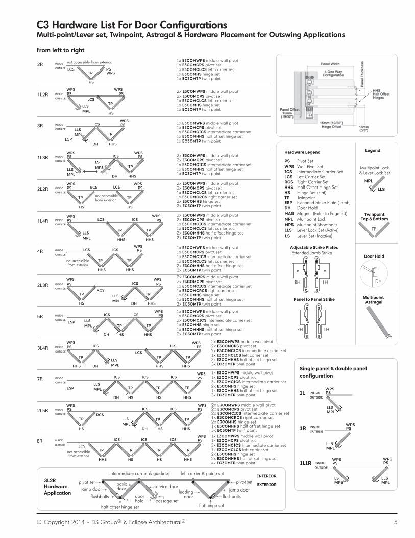
1x E3COMWPS middle wall pivot1x E3COMCPS pivot set1x E3COMCRCS right carrier set1x E3COMHS hinge set1x EC3OMTP twin point
2x E3COMWPS middle wall pivot2x E3COMCPS pivot set1x E3COMCRCS right carrier set1x E3COMHS hinge set1x EC3OMTP twin point
1x E3COMWPS middle wall pivot1x E3COMCPS pivot set1x E3COMCICS intermediate carrier set1x E3COMHHS half offset hinge set1x EC3OMTP twin point
2x E3COMWPS middle wall pivot2x E3COMCPS pivot set1x E3COMCICS intermediate carrier set1x E3COMHHS half offset hinge set1x EC3OMTP twin point
1x E3COMWPS middle wall pivot1x E3COMCPS pivot set1x E3COMCICS intermediate carrier set1x E3COMCRCS right carrier set2x E3COMHHS half offset hinge set2x EC3OMTP twin point
2x E3COMWPS middle wall pivot2x E3COMCPS pivot set1x E3COMCICS intermediate carrier set1x E3COMCRCS right carrier set2x E3COMHHS half offset hinge set2x E3COMTP twin point
2x E3COMWPS middle wall pivot2x E3COMCPS pivot set1x E3COMCICS intermediate carrier set1x E3COMCLCS left carrier set1x E3COMHS hinge set1x E3COMHHS half offset hinge set2x EC3OMTP twin point
1x E3COMWPS middle wall pivot1x E3COMCPS pivot set2x E3COMCICS intermediate carrier set1x E3COMHS hinge set1x E3COMHHS half offset hinge set2x EC3OMTP twin point
2x E3COMWPS middle wall pivot2x E3COMCPS pivot set2x E3COMCICS intermediate carrier set2x E3COMHHS half offset hinge set2x EC3OMTP twin point
1x E3COMWPS middle wall pivot1x E3COMCPS pivot set3x E3COMCICS intermediate carrier set2x E3COMHS hinge set1x E3COMHHS half offset hinge set3x EC3OMTP twin point
2x E3COMWPS middle wall pivot2x E3COMCPS pivot set2x E3COMCICS intermediate carrier set1x E3COMCRCS right carrier set3x E3COMHHS half offset hinge set3x EC3OMTP twin point
2x E3COMWPS middle wall pivot2x E3COMCPS pivot set2x E3COMCICS intermediate carrier set1x E3COMCLCS left carrier set2x E3COMHS hinge set1x E3COMHHS half offset hinge set3x EC3OMTP twin point
2x E3COMWPS middle wall pivot2x E3COMCPS pivot set3x E3COMCICS intermediate carrier set1x E3COMHS hinge set2x E3COMHHS half offset hinge set3x EC3OMTP twin point
1x E3COMWPS middle wall pivot1x E3COMCPS pivot set2x E3COMCICS intermediate carrier set1x E3COMCRCS right carrier set1x E3COMHS hinge set2x E3COMHHS half offset hinge set3x EC3OMTP twin point
C3 Hardware List For Door ConfigurationsMulti-point/Lever set, Twinpoint, Astragal & Hardware Placement for Outswing Applications
From left to right
Inswingapplication“D”pullhandleoption
INTERIOR
EXTERIOR
OUTSWING3L
INSWING
INTERIOR
EXTERIOR
3LI
How To Determine Swing Of Systems
TP TP
3L
INTERIOR
EXTERIOR
TP TP5RI
INTERIOR
EXTERIOR
Use“D”pullhandleonexitdoor(outswingsystem)wherepassageset/locknotrequired.Useflushboltstopandbottomtolockdoorfromtheinsideonly.Note:exitdoornotaccessiblefromexterior.
Configurationisalwaysdeterminedwhenviewingsystemfromexteriorside,goingfromlefttoright.
outswingapplication“D”pullhandleoption
Useone“D”pullhandleoneachpairofinswingdoorstopullopenandclosedoors.
1x E3COMCLCS Left Carrier Set1x E3COMCRCS Right Carrier Set1x E3COMHS Hinge Set1x E3COMTP Twin Point
Hardware Legend
PS Pivot SetWPS Wall Pivot SetICS Intermediate Carrier SetLCS Left Carrier SetRCS Right Carrier SetHHS Half Offset Hinge SetHS Hinge Set (Flat)TP Twinpoint
TP
ESP Extended Strike Plate (Jamb)DH Door HoldMAG Magnet
Door Hold
DH
MPL Multipoint LockMPS Multipoint ShootboltsLLS Lever Lock Set (Active)
Multipoint Lock& Lever Lock Set
TwinpointTop & Bottom
MultipointAstragal
Legend
Per pair of doors:
MPLLLS
Floating Door Pairs
LS Lever Set (Inactive)
DSSPLK730-60RH DSSPLK729-60LH DSSPLK732-60RH DSSPLK731-60LH
Adjustable Strike Plates
Panel to Panel Strike Extended Jamb Strike
RH LHRH LH
DSSPLK654adjustable hook strikefor panel to panel or jamb
© Copyright 2014 • DS Group® & Eclipse Architectural® 5
TP
Door Hold
DH
Multipoint Astragal
TwinpointTop & Bottom
Multipoint Lock& Lever Lock Set
MPL
LLS
Hardware Legend
PS Pivot SetWPS Wall Pivot SetICS Intermediate Carrier SetLCS Left Carrier SetRCS Right Carrier SetHHS Half Offset Hinge SetHS Hinge Set (Flat)TP TwinpointESP Extended Strike Plate (Jamb)DH Door HoldMAG Magnet (Refer to Page 33)MPL Multipoint Lock
LLS Lever Lock Set (Active)
Legend
LS Lever Set (Inactive)
MPS Multipoint Shootbolts
Adjustable Strike Plates
Panel to Panel Strike
Extended Jamb Strike
RH LH
RH LH
WPSPS
MPLLLS
WPSPS
MPLLLS
PSWPS
MPSLS
Single panel & double panel configuration
1L1R
PSWPS
MPLLLS
INSIDE
OUTSIDE1L
INSIDE
OUTSIDE
INSIDE
OUTSIDE
1R
C3 Hardware List For Door ConfigurationsMulti-point/Lever set, Twinpoint, Astragal & Hardware Placement for Outswing Applications
RCS
RCS
RCS
LCS
LCS
LCS
LCS
LCS
LCS
LCS
HS
HS
HS
HS
HS
HS
HS
HS
HSHS
HS
PS
PS
PS
PS
PS PS
PS
PS PS
PS
PS PS
PS
PS PS
PS
PS
PS
PS
PS
HHS
HHS
HHS
HHS
HHS
HHS
HHS
HS
HHS
HHS HHS
HHS
HHSHHS
HHS
ICS
ICS
ICS
ICS
ICS
ICS
ICS
ICS
ICS ICS ICS
ICS
ICS ICS
ICS
ICS
ICS
WPS
WPS
WP WS PS
WPS
WPS
WPS
WPS
WPS
WP WS PS
WPS
WPS
WPS
WP WS PS
WPS
WPS
WPS
WPS
not accessible from exterior.
not accessiblefrom exterior.
not accessiblefrom exterior.
not accessiblefrom exterior.
DHESP
DH
DH
ESP
DH
DH
ESP
DH
DH
TP
TP
TP
TP
TP TP
TP TP
TP TP
TP TP
TP TP
TP TPTP
TP TPTP
TP TPTP
TP TPTP TP
MPLLLS MPS
LS
HHS
MPLLLS
MPLLLS
MPLLLS
MPLLLS
MPLLLS
MPLLLS
MPLLLS
MPLLLS
1x E3COMWPS middle wall pivot1x E3COMCPS pivot set1x E3COMCLCS left carrier set1x E3COMHS hinge set1x EC3OMTP twin point
2x E3COMWPS middle wall pivot2x E3COMCPS pivot set1x E3COMCLCS left carrier set1x E3COMHS hinge set1x EC3OMTP twin point
1x E3COMWPS middle wall pivot1x E3COMCPS pivot set1x E3COMCICS intermediate carrier set1x E3COMHHS half offset hinge set1x EC3OMTP twin point
2x E3COMWPS middle wall pivot2x E3COMCPS pivot set1x E3COMCICS intermediate carrier set1x E3COMHHS half offset hinge set1x EC3OMTP twin point
2x E3COMWPS middle wall pivot2x E3COMCPS pivot set1x E3COMCLCS left carrier set1x E3COMCRCS right carrier set2x E3COMHS hinge set2x EC3OMTP twin point
2x E3COMWPS middle wall pivot2x E3COMCPS pivot set1x E3COMCICS intermediate carrier set1x E3COMCLCS left carrier set2x E3COMHHS half offset hinge set2x EC3OMTP twin point
1x E3COMWPS middle wall pivot1x E3COMCPS pivot set1x E3COMCICS intermediate carrier set1x E3COMCLCS left carrier set2x E3COMHHS half offset hinge set2x EC3OMTP twin point
2x E3COMWPS middle wall pivot2x E3COMCPS pivot set1x E3COMCICS intermediate carrier set1x E3COMCRCS right carrier set1x E3COMHS hinge set1x E3COMHHS half offset hinge set2x EC3OMTP twin point
1x E3COMWPS middle wall pivot1x E3COMCPS pivot set2x E3COMCICS intermediate carrier set1x E3COMHS hinge set1x E3COMHHS half offset hinge set2x EC3OMTP twin point
1x E3COMWPS middle wall pivot1x E3COMCPS pivot set3x E3COMCICS intermediate carrier set2x E3COMHS hinge set1x E3COMHHS half offset hinge set3x EC3OMTP twin point
2x E3COMWPS middle wall pivot2x E3COMCPS pivot set2x E3COMCICS intermediate carrier set1x E3COMCRCS right carrier set2x E3COMHS hinge set1x E3COMHHS half offset hinge set3x EC3OMTP twin point1x E3COMWPS middle wall pivot1x E3COMCPS pivot set3x E3COMCICS intermediate carrier set1x E3COMCLCS left carrier set2x E3COMHS hinge set2x E3COMHHS half offset hinge set4x EC3OMTP twin point
2x E3COMWPS middle wall pivot2x E3COMCPS pivot set2x E3COMCICS intermediate carrier set1x E3COMCLCS left carrier set3x E3COMHHS half offset hinge set3x EC3OMTP twin point
From left to right
intermediate carrier & guide set left carrier & guide set INTERIOR
EXTERIORpivot set
flushbolts flushbolts
half offset hinge set flat hinge setpassage set
pivot set
jamb doorjamb doorbasic door
leadingdoor
service door
door hold
3L2R Hardware Application

6 © Copyright 2014 • DS Group® & Eclipse Architectural®
NO SCALENO SCALE
Additional hinge (fourth) recommended for doors over 8 ft (2438mm) in height.
Also use as fifth hinge if required.
Replacement part bottom pivot housing onlyEC3PIVOTG gasket for under c3 bottom pivot. apply to bottom before fastening pivot into sill channel.
E3COMCPSPivot set, 2 piece set
Replacement part(cup only for middle pivot)
jamb mounted middle pivot for doors over 88” (2235mm)
E3COMWPSCentre pivot set, 1 piece
E3COMCLCSLeft carrier set, 2 piece set
E3COMCRCS Right carrier set, 2 piece set
E3COMCICSintermediate carrier set3 piece set
E3COMEHInterior D pull handlefor inswing doors1 piece
E3COMHSHinge set with middle handle for outswing doors, 3 piece set
E3COMHSNHSHinge set with no middle handle for inswing doors3 piece set
E3COMHHSHalf offset hinge set with middle handle for outswing doors,3 piece set
E3COMHHNHSHalf offset hinge set with no middle handle for inswing doors, 3 piece set
Intermediate carrier set with additional hinge
Hinge set with handle for outswing doors
Hinge set no handle for inswing doors
Half offset hinge set with handle for outswing doors
Half offset hinge set no handle for inswing doors
concealed bottom guide
concealed bottom guide
concealed bottom guide
concealed bottom guide
flat (outswing doors)
flat (inswing doors)
offset (outswing doors)
offset (inswing doors)
C3 Parts Selection

© Copyright 2014 • DS Group® & Eclipse Architectural® 7
NO SCALE
DSSPLK729-60LH
Parts Identification: Multipoint Components
Panel To Panel Strike Extended Jamb Strike Hook Strike
Shootpoint Set
left left right non handed
6” (152.4mm) top6” (152.4mm) top
8” (203.2mm) bottom8” (203.2mm) bottom
Active Handle Set Inactive Handle Set
DSSPLK731-60LHDSSPLK730-60RH DSSPLK732-60RH DSSPLK654
DSSPLSB100-60 (SET)
Enhanced Shootpoint Set
DSSPLSB24-60 DSSPLSB27-60
DSSPL 2325-60
Face Plate Extension
DSPF1341 DSPF1342
right
14” (355.6mm)
8 © Copyright 2014 • DS Group® & Eclipse Architectural®
NO SCALE
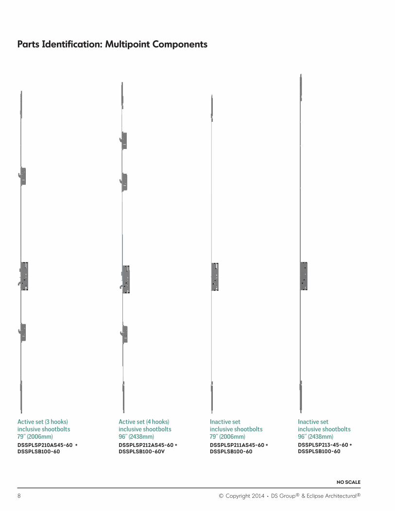
Parts Identification: Multipoint Components
Active set (3 hooks)inclusive shootbolts79” (2006mm)
Active set (4 hooks)inclusive shootbolts 96” (2438mm)
Inactive setinclusive shootbolts79” (2006mm)
Inactive setinclusive shootbolts96” (2438mm)
DSSPLSP210AS45-60 +DSSPLSB100-60
DSSPLSP212AS45-60 + DSSPLSB100-60V
DSSPLSP211AS45-60 + DSSPLSB100-60
DSSPLSP213-45-60 + DSSPLSB100-60

© Copyright 2014 • DS Group® & Eclipse Architectural® 9
NO SCALE
Parts Identification: Twinpoint Components
End Cap GearboxShootbolt
Gearbox Brace
Rod Attachment
Extension RodHandle
EC3TWINPOINT
Twinpoint

10 © Copyright 2014 • DS Group® & Eclipse Architectural®
NO SCALE
Panel Stop (Panel Hold Magnet) Panel Stop (Panel Hold Magnets)Panel Stop (Latching Panel Hold)
Parts Identification: Miscellaneous Components
KT740DH KT740DH KTDCA
Parts Identification: Hardware Fasteners
Twinpoint Handle Set Screw Shootbolts50 x 5.4mm (Phillips FH)
Astragal / Endcap/ Multipoint Screw8 - 32 x 1-1/2” (Square FH)
Pivot Set Bottom Screw8 x 1” (Phillips PH)
Handle Set Screw 71.3 x 4.8mm (Phillips)
Panel Corner / Frame Corner10 x 2” (Square PH)
Frame Installation Screw12 x 3” (Square PH)
Hinge Screw/ Strike Plates / Enhanced8 - 32 x 3/4” (Phillips FH)
Corner Key Nut & Bolt M8 5/16” x 1-1/4”
Centre Wallpivot Screw8 x 1-1/2” (Phillips FH)
EC3PANELSCREW EC3FRAMESCREW
EC3HSPSCREW
EC3MPSCREW EC3FNUTM8 EC3FPOINTM8X1.25

© Copyright 2014 • DS Group® & Eclipse Architectural® 11
NO SCALE
Parts Identification: Weather Seal And Sealants
Panel Weather Seal Panel Weather Seal
Pile with kerf leg for active panel
Gasket With Adhesive For Both Ends Of Sill
Frame / Astragal Weather Strip
Glazing Gasket (Exterior)Pile For Head
Gasket For Lever Lock Set
Glazing Gasket (Interior)
Gasket With Adhesive For Hinge
standard version enhanced version
KT423 KT426 DS426
EC3GGASKETEXT
EC3AP500
EC3GGASKETINTDSP108-20
EC3HINGEGASKET EC3SILLGASKET
3/8” (9.5mm)
1-1/2” (38mm)
NO SCALE
DS672DW White pile with adhesive for top & bottom of astragals
DS672DBL Black pile with adhesive for top & bottom of astragals
DS672DW White pile with adhesive for top & bottom of astragals
DS672DBL Black pile with adhesive for top & bottom of astragals
1/2” (12.7mm)
2” (50.8mm)
Placement of pile weatherseal at top & bottom of astragal
Placement of pile weatherseal at top & bottom of astragal
NO SCALE

12 © Copyright 2014 • DS Group® & Eclipse Architectural®
NO SCALE
Parts Identification: Extrusions
Head Track Ada Sill
Common Stile
T-Astragal
Recessed Stile
Snap In Bead
Sill Floor Channel
Multipoint/Beveled Stile
6mm Glass Adaptor
Side Jamb
Top & Bottom rail
MP - AstragalCorner Key
14mm Glass Adaptor Pvc Channel Insert
EC3HEAD EC3SILL EC3HEAD EC3ADASILL EC3FCHANNEL
EC3RAIL EC3CSTILE
Frame
Panel
EC3RESTILE EC3MPSTILE
EC3CORNERKEY12M EC3MPASTRAGAL EC3TASTRAGAL EC3SBEAD
EC3REDUCER14G EC3REDUCER6GHigh Security L-Bracket
© Copyright 2014 • DS Group® & Eclipse Architectural® 13
NO SCALE
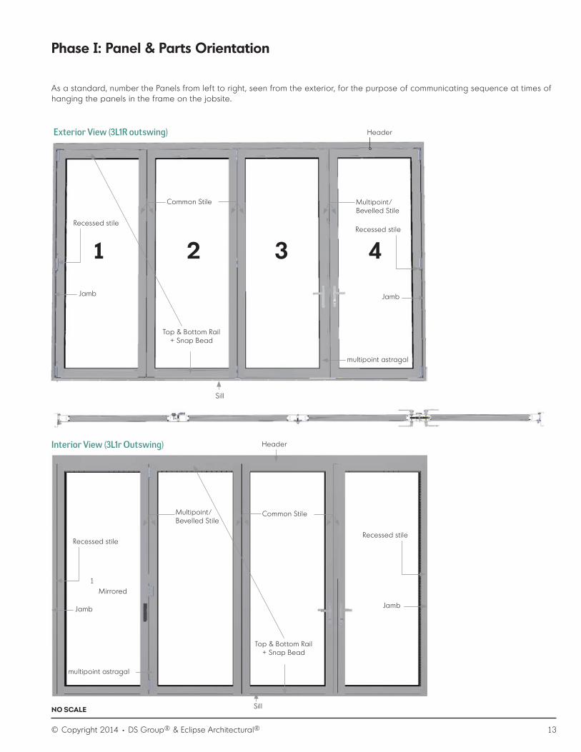
Phase I: Panel & Parts Orientation
1
1
2 3 4
As a standard, number the Panels from left to right, seen from the exterior, for the purpose of communicating sequence at times of hanging the panels in the frame on the jobsite.
Recessed stile
Recessed stile
Recessed stile
Recessed stile
Mirrored
Jamb
Jamb
Jamb
Jamb
multipoint astragal
multipoint astragal
Top & Bottom Rail+ Snap Bead
Top & Bottom Rail+ Snap Bead
Common Stile
Common Stile
Multipoint/ Bevelled Stile
Multipoint/ Bevelled Stile
Sill
Sill
Header
Header
Exterior View (3L1R outswing)
Interior View (3L1r Outswing)

14 © Copyright 2014 • DS Group® & Eclipse Architectural®
NO SCALE
Design Criteria
Panel orientation
Panel Design - Uneven Faces
Drawing A
Drawing B
DRAWING A: Ensure extrusions “mate” correctly by using the “T” as your reference point. If your application is an outswing configuration, the “T” will be located on the exterior. If your application is an inswing configuration, the “T” will be located on the interior.
DRAWING B: Ensure the rail is evenly spaced in between the stiles.
Top / Bottom Rail + Snap Bead
Top / Bottom Rail
2-5/32” (55mm)
2-1/4” (58mm)
Step 1.1a C3 Standard / C3 Enhanced Step 1.1b C3 Storm
Step 1.2
C3 Storm: It is recommended to first dry-fit components before applying 3M product.
Assembly 1st Panel
Recessed stile
Top & Bottom Rail
Corner key requires 2 nuts & bolts. In order to seal of joint, please run a bead of silicone on rail end prior to assembly.
Apply 3M Scotch-Weld Low-Odor Acrylic Adhesive (not provided by Eclipse Architectural) on corner key and all touching areas of the rail walls prior inserting the stile into rails (green color as per image).
Step 1.3 Step 1.4
4 / 10 x 2” (Square PH)
Caution: It is recommended to use screw wax to prevent screw from snapping. Clamp corner to ensure proper alignment.
Important considerations during panel assembly:

© Copyright 2014 • DS Group® & Eclipse Architectural® 15
NO SCALE
Important assembly consideration: Prior to glazing, the loose stile will need to be dry-fitted for glazing and reducer bar alignment.
a. IG unit - 15/16” (24mm)
Step 1.5 Assemble top & bottom rails to one stile
Step 1.6 - Determine applicable glazing options:
Top & Bottom Rail
b. Single glass - 1/4” (6.4mm) - adding 6mm glass adopter required on both interior and exterior side
c. Hurricane glass - 9/16” (14.3mm) – 14mm glass adopter required
2-1/4”
58mm
3-17/32”
89mm

16 © Copyright 2014 • DS Group® & Eclipse Architectural®
NO SCALE
Important glazing consideration:Always insert interior glazing gasket on the opposite face of where the “T” on the extrusion is located.
Step 1.7 - Insert interior glazing gasket
Important glazing block consideration (3L1R unit seen from exterior):
• Purple = glazing blocks • Apply minimal amount silicone to keep the glazing blocks from slipping.• Ensure that installed glass in panel does not shift at times of transportation
Step 1.8 Setting-blocks (not supplied by Eclipse Architectural)
a. IG unit - 15/16” (23.8mm) Setting block : 1/2”
b. Single glass - 1/4” (6.4mm) Setting block : 1/2”
c. Hurricane glass - 9/16” (14.3mm) Setting block : 3/8”
Step 1.9 Insert glass
Run a bead of silicone prior to adaptor placement into stile and rails
Run a bead of 3M Scotch-Weld Low-Odor Acrylic Adhesive DP-810 prior to adaptor placement into stile and rails
© Copyright 2014 • DS Group® & Eclipse Architectural® 17
NO SCALE
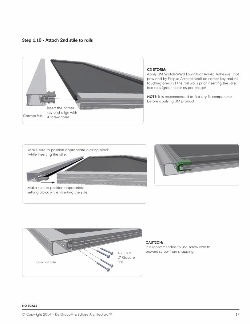
Step 1.10 - Attach 2nd stile to rails
Common Stile
C3 STORM:Apply 3M Scotch-Weld Low-Odor Acrylic Adhesive (not provided by Eclipse Architectural) on corner key and all touching areas of the rail walls prior inserting the stile into rails (green color as per image).
NOTE: It is recommended to first dry-fit components before applying 3M product.
Make sure to position appropriate glazing block while inserting the stile.
Insert the corner key and align with 4 screw holes
Make sure to position appropriate setting block while inserting the stile.
CAUTION:It is recommended to use screw wax to prevent screw from snapping.4 / 10 x
2” (Square PH)Common Stile

18 © Copyright 2014 • DS Group® & Eclipse Architectural®
NO SCALE
Step 1.11 - Insert exterior glazing gasket
Step 1.12 - Apply snap bead and roll in the exterior horizontal glazing gasket on top & bottom rail
Important consideration while glazing:
1. Always insert exterior glazing gasket on the face of where the “T” is located.2. Always insert interior glazing gasket on the opposite face of where the “T” is located.
1. Apply snap bead and snap in place2. Cut the glazing gasket to length (ends 2 x 90˚)3. Roll the exterior glazing gasket into place.
1. Cut the glazing vertical gasket to length (copy angle of horizontal gaskets)
2. Roll/apply the vertical exterior glazing gasket into place.3. Apply minimal amount of silicone in the corners where the
gaskets meet.

© Copyright 2014 • DS Group® & Eclipse Architectural® 19
NO SCALE
Step 1.13 - Apply hinges
Pivot Set (PS)
4/ 8 - 32 x 3/4” (Phillips FH)Screw holes are pre-drilled
Apply top Pivot hinge in PHase II
Recessed stile
Common Stile
Important hinge consideration:Position all hinges in a way that one pushes the hinge away from the centre of the style as per arrow so that slight space occurs between the face of the panel and the knuckle of the hinge.
Space between face (reveal) of the panel and the hinge
Recessed stile
Apply half offset hinge set (HHS)
3/ 8 - 32 x 3/4” (Phillips FH) - Screw holes are pre-drilled
Recessed stile
Common Stile

20 © Copyright 2014 • DS Group® & Eclipse Architectural®
NO SCALE
top
bottom
Twinpoint is not pre-assembled or pre-cut to length.
Important consideration:Retract shootbolts prior to inserting twinpoint into stile by rotating twinpoint handle upwards.
Step 1.14 - Apply Twinpoint
Flat side of shootbolt facing side of the panel
Slide the gearset into the stile, while passing corner bolts by holding gearbox close to external wall
Common Stile
Mount twinpoint handle set to the gearbox while twinpoint handle is pointing up (retract position)

© Copyright 2014 • DS Group® & Eclipse Architectural® 21
NO SCALE
2 / 50 x 5.4mm (Phillips FH)
2 / 8 x 32” x 1 (Square FH)
NOTE:• 2 / Endcap – apply bead of clear silicone on edge of stile extrusion• Pre-drill end-cap for screws
Recessed stile

22 © Copyright 2014 • DS Group® & Eclipse Architectural®
NO SCALE
NOTE:1. When handle in pointing up position, the shootbolt should
be retracted, flush with the installed endcap.2. Ensure that when rotating the twinpoint handle, the handle
rotates towards the glass opening of the panel.
C3 Enhanced and C3 Storm program as per design carries two twinpoint sets.
Step 1.15 - Apply weather seal & sealants
Recessed stile
Generic Panel Weather Seal placement orientation
Common stile
Apply hinge seal
Apply weatherseal to edge of hinge flap. (same applies to the other hinges on this panel)
Do not run weatherseal to single hinge flap.
Apply weatherseal from edge of flap to top of door.

© Copyright 2014 • DS Group® & Eclipse Architectural® 23
NO SCALE
Step 2.1 - Apply intermediate carrier set (ICS)
6/ 8 - 32 x 3/4” (Phillips FH)Screw holes are pre-drilled
Apply top Intermediate hinge at time of hanging the panel in the frame.
Brush Sweep To Bottom Of Panels
Assembly 2nd Panel (2 will go through similar assembly process steps as described for Panel 1)
Common stile
INTERIOREXTERIOR
Panel to Floor Channel Detail
finished floor line
glazing block by other
3/8” (10mm)
7/8” (22.1mm)
19/64” (7.4mm)
DS158 brushed sweep
11/16 (17.5mm)
7/16 (11.1 mm)
Panel to ADA Sill Detail
INTERIOREXTERIOR
finished floor line
blockoutflooring forsill channel
finished floor line
3/8” (10mm)
19/64” (7.4mm)
11/16 (17.5mm)
7/16 (11.1 mm)
DS158
brushed sweep
glazing block by other
1/2”12.7 mm
24 © Copyright 2014 • DS Group® & Eclipse Architectural®
NO SCALE
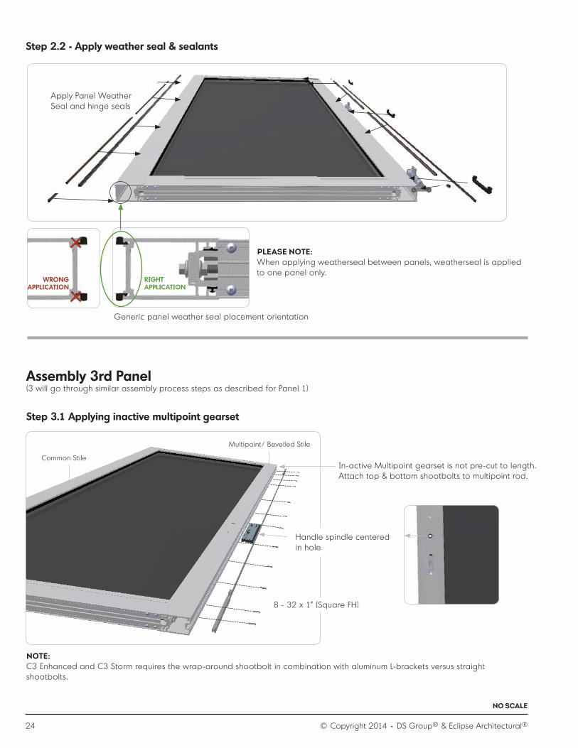
Step 2.2 - Apply weather seal & sealants
Generic panel weather seal placement orientation
Handle spindle centered in hole
8 - 32 x 1” (Square FH)
Apply Panel Weather Seal and hinge seals
Assembly 3rd Panel (3 will go through similar assembly process steps as described for Panel 1)
Step 3.1 Applying inactive multipoint gearset
Common Stile
Multipoint/ Bevelled Stile
In-active Multipoint gearset is not pre-cut to length. Attach top & bottom shootbolts to multipoint rod.
NOTE:C3 Enhanced and C3 Storm requires the wrap-around shootbolt in combination with aluminum L-brackets versus straight shootbolts.
PLEASE NOTE:When applying weatherseal between panels, weatherseal is applied to one panel only.
WRONG APPLICATION
RIGHT APPLICATION

© Copyright 2014 • DS Group® & Eclipse Architectural® 25
NO SCALE
multipoint/ bevelled stile multipoint/ bevelled stile
2/ 8 - 32 x 3/4” (Phillips FH)
2/ 8 - 32 x 1-1/2” (Square FH)
L-bracket
8 - 32 x 1-1/2” (Square FH)
Step 3.2 Applying multipoint astragal
Multipoint Astragalmultipoint/ bevelled stile
Common Stile

26 © Copyright 2014 • DS Group® & Eclipse Architectural®
NO SCALE
Step 3.2 Applying T-astragal (2L1R configuration example)
Step 3.2 Applying multipoint strike plates
Step 3.3 Apply weather seal & sealants
It is recommended to use a construction handle during the time of constructions and only apply handle set after jobsite activities are finalized, this to prevent damage, loss, and or theft.
8 - 32 x ½“ (Phillips FH)
T- Astragal
8 - 32 x 1 ½” (Square FH)
Apply panel Weather Seal in 1st groove and Pile with adhesive on top and bottom of Astragal.
End of Weather Seal flush with bottom of astragal
Pile flush with face of astragal , top & bottom
© Copyright 2014 • DS Group® & Eclipse Architectural® 27
NO SCALE
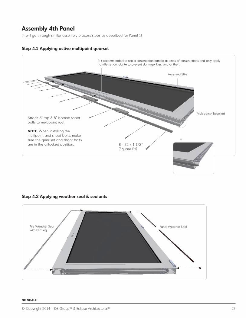
Attach 6” top & 8” bottom shoot bolts to multipoint rod.
NOTE: When installing the multipoint and shoot bolts, make sure the gear set and shoot bolts are in the unlocked position. 8 - 32 x 1-1/2”
(Square FH)
Assembly 4th Panel (4 will go through similar assembly process steps as described for Panel 1)
Step 4.1 Applying active multipoint gearset
Step 4.2 Applying weather seal & sealants
It is recommended to use a construction handle at times of constructions and only apply handle set on jobsite to prevent damage, loss, and or theft.
Recessed Stile
Multipoint/ Bevelled
Pile Weather Seal with kerf leg
Panel Weather Seal

28 © Copyright 2014 • DS Group® & Eclipse Architectural®
NO SCALE
3 / 10 x 2” (Square PH)
3 / 10 x 2” (Square PH)
PHase II: Frame Assembly
Step A.1) Assemble bottom corner
Step A.2) Assemble top corner
Sill to Jamb Gasket
Sill
Note that track insert is in place prior to screwing sill to the jamb.
PRE-CAUTION: it is recommended to use screw wax to prevent screw from snapping.
NOTE: Do not use this screw chase
Jamb
PRE-CAUTION: it is recommended to use screw wax to prevent screw from snapping

© Copyright 2014 • DS Group® & Eclipse Architectural® 29
NO SCALE
Step A.3) Apply horizontal frame weather seal
Step A.4) Apply vertical frame weather seal
Jamb
Header
Cut weather-strip ends at 90 degrees.
TIP: In order to insert Weather Seal smoothly, apply paraffin wax in Weather Seal grooves.
Jamb Header
Cut vertical Weather Seal ends at 45 degree angle to match horizontal weather-stripping.
Jamb
NOTE: Apply minimal amount of clear silicone between 45 degree angled cut ends and horizontal Weather Seal.
JambSill
C3 Enhanced and C3 Storm apply DS426 Weather Seal on frame.
Slide Pile-Fin Weather Seal (non-adhesive) into the slot.

30 © Copyright 2014 • DS Group® & Eclipse Architectural®
NO SCALE
Detail C : Header
Detail A : Sill
Detail B : Jamb
Step A.4) Jobsite preparation considerations rough opening
Step A.5) Frame placement into rough opening
1. Ensure correct rough opening specifications :a) Measure according to signed Eclipse Architectural shop drawingb) Plumb openingc) Level openingd) Square opening
2. Make sure the frame header is designed to withstand the dead loads of all Panels including glass plus momentum and impact loading since it is a top-hung Panel system. Rough opening header must not deflect more than 1/16” (2 mm) when carrying the weight of the Panels according to hardware suppliers’ specifications.
3. Ensure the head of the Folding Panel system can be securely fastened to the header components of existing structural header beam.
4. Recommended wood framing for opening or a continuous plane of structural wood to maintain stability, ease of fastening and securing.
5. Each panel can weigh up to a maximum of 176 lbs (80 kg). Weigh one Panel or consult quote to determine total weight of Folding Panel system or contact Eclipse Architectural for the weight of each Panel.
NOTE:1. Ensure sill is plumb and level2. “Sill sag” to be no more than 1/6 *(2mm) at centre span3. “Sill bow” to be avoided at any location of the sill4. Anchoring screws are supplied by Eclipse Architectural5. Envelope details are not included in this guide. Please consult with your local building codes.6. In order to reach enhanced performance (>DP60), use extra screw line located in the shootbolt channel as per images
for head / jamb / sill.7. Seal off all installation screw holes in frame with silicone.
DETAIL A: SILL

© Copyright 2014 • DS Group® & Eclipse Architectural® 31
NO SCALE
NOTE: 1. The supplied 3” (75mm) PH track screw is a suggested screw size only. The final screw
used must penetrate at least 1 ½” (38mm) into the rough opening structural header beam that is to carry the accumulative Panel load. The size of the bolt head should not interfere with any carrier wheels.
2. The material used for insulating the shim space should be non-expandable material.3. Avoid the head from sagging after panels are installed and after full roof load is in
place. We recommend installing the header with a slight bow (crown), but not more than 1/8” (3mm) over the full system length.
4. Anchoring screws are supplied by Eclipse Architectural.
DETAIL C: HEADER
C3 Enhanced/ C3 Storm extra installation screw
Step A.6) Loading the head track
NOTE:1. Before installing the carriers, ensure that the track is clear of all debris and there is no contamination of metal parts that
could restrict Panel movement or damage wheels.2. Use a clean cloth to lubricate the track and the wheels with a small quantity of white petroleum jelly (Vaseline) not
provided by Eclipse Architectural.3. Consult the shop drawings and load sequentially to applicable configuration.4. Load carrier sets through square hole in track.
Header
Jamb
NOTE:1. To accommodate for the wall pivot cup, it is recommended to pre-drill a 11/16” (17mm)
diameter hole in the rough opening due to the protruding wall cups ( ½” or 12mm).2. Bow of the jamb to be kept to a minimum of 1/8” (3mm)3. Anchoring screws are supplied by DS group4. It is recommended to use a continuous board (as alternate apply pieces) that will act as a
back-up in the hollow jamb.5. Seal off backside of middle pivot cup(s) with silicone
C3 Storm extra installation screw hole
DETAIL B: JAMB

32 © Copyright 2014 • DS Group® & Eclipse Architectural®
NO SCALE
Step A.7) Determine panel sequence
Detail A.7.3
Step A.7.2
Step A.7.1
Step A.7.1.a) Bottom pivot set placement Step A.7.1.b) Receive panel onto pivot
1 2 3 4
We suggest the panels are identified for the purpose of communicating sequence.
2 / 8 x 1”- 25mm (Phillips PH)NOTE: Seal off fastener holes
Sill
Ensure when inserted in track, the hinge pin is located on the exterior as per image.
Recessed stile
Jamb
Step A.7.2) Install cup for wall-pivot
NOTE:1. Seal off holes for Pivot Cups with silicone.2. Insert the hinge cap into the Bearing Tube first and then slide
hinge pin down to engage into wall-pivot cup.
CAUTION: Always support weight of Panel panels with flat/pry bar or similar tool when locating and securing any pivot or carrier vertical adjustment.
Apply gasket underpivot.
Black plastic sleeve can only go on one way

© Copyright 2014 • DS Group® & Eclipse Architectural® 33
NO SCALE
NOTE:To ensure proper operation of Folding Panel System, insert the hinge while aligning the slot in the hinge flap with the rib on the Bearing Tube.
Step A.7.3) Mounting the top wall pivot hinge to 1st panel
Step A.8) Adjust panel height
4/8 - 32 x 3/4” (Phillips FH)
Important hinge consideration:Position all hinges in a way that one pushes the hinge up as per arrow.
Recessed Stile
NOTE:Adjust clearance between top of the panel to bottom of the head track to 13/64" (5 mm) by using a flathead screw driver into the yellow shipping clip.
CAUTION: Always support weight of Panel panels with flat/pry bar or similar tool when locating and securing any pivot or carrier vertical adjustment.
13/64” (5 mm)

34 © Copyright 2014 • DS Group® & Eclipse Architectural®
NO SCALE
Step A.9 – Adjust panel reveal with jamb
Step A.10) Hanging 2nd panel: mounting the top intermediate carrier to 2nd panel
Jamb
RecessedStile
Sill
5/32” (4 mm)
NOTE:Adjust clearance between jamb and panel to 5/32” (4 mm) by using a long shafted Phillips screw driver as per image. Clearance dimension is measured when panel is in closed position.
NOTE:Adjust clearance between top of the panel to bottom of the head track to 13/64” (5 mm) by using a flathead screw driver into the yellow shipping clip.
6/ 8 - 32 x 3/4” (Phillips FH)

© Copyright 2014 • DS Group® & Eclipse Architectural® 35
NO SCALE
Step A.11) Hanging 2nd panel – Connecting 2nd panel to 3rd panel
6/ 8 - 32 x ” (Phillips FH)
Step A.12) Hanging 3rd panel: mounting the top intermediate carrier to 2nd panel
Step A.13) Hanging 4th panel: repeat steps a.7.1 - a.7.3
3/ 8 - 32 x 3/4” (Phillips FH)

36 © Copyright 2014 • DS Group® & Eclipse Architectural®
NO SCALE
Phase III: Completion, Adjustments and Service
9 Step 1: Ensure the multipoint is operating smoothly. (if applicable)
9 Step 2: Ensure equal reveal to left and right of the system.
9 Step 3: Ensure horizontal and vertical alignment.
9 Step 4: Carrier pins at the top pivots, intermediate and end carriers are supplied with a yellow plastic shipping clip, which is
installed to make the initial adjustment very easy.
9 Step 5: Insert a flathead screwdriver into the slot to rotate the pin.
9 Step 6: When the correct adjustment is reached and the Panels operate well, remove the shipping clip.
9 Step 7: The blade will automatically snap into place once the blade and slot are aligned.
9 Step 8: To readjust at a later date, simply pull the blade down to disengage it from the slot and rotate the pin.
9 Step 9: Mount panel hold(s) to door at desired location/ direction with 8-32” x 3/4” screws (9/64” tapped screw holes), keeping
in mind the distance between the handle-set(s), alignment of Holds with one another and adjust the Hold to desired friction to
open and close.
Completion Check List
Folding Door Adjustments
Using Surelock™:
1. Surelock™ is supplied with a yellow plastic shipping clip installed
to make initial adjustment very easy.
2. Insert a flathead screwdriver into the slot to rotate the pin.
3. When correct adjustment is reached and doors operate well,
remove the shipping clip
4. Surelock™ will automatically snap into place when the blade
and slot are aligned.
5. To re-adjust at a later date, simply pull the blade down to
disengage it from the slot and rotate the pin.
Carrier pins at the top pivots, intermediate and end carriers support the full door weight and it is here that the height of the panels
is adjusted. Surelock™ ensures that once the heights are set, they stay set.
1
2 3 4 5

© Copyright 2014 • DS Group® & Eclipse Architectural® 37
NO SCALE
Multipoint Door Adjustments
Panel Handle Application
All strike plates are adjustable to en sure smooth fine tuning, by using Phillips screw driver to loosen adjust screws, sliding the strike box to desired location and fasten the adjustments screws.
Adjustment screws (Phillips)
Ensure slotted face of the spindle is facing down to receive the insert screw

38 © Copyright 2014 • DS Group® & Eclipse Architectural®
Recommended Product Care after Placement
1. Keep the plastic protection inserts on the sill at all times! Create a sturdy bridge to protect sill during construction phase. In
addition, place a ‘bridge’ while system is in open position and protect the side jambs of the Folding Door frame from damage.
2. Protect the Folding Door system from the following :
• Stucco : Causes etching on aluminum clogs the track and damages rollers.• Drywall : clogs the system tracks; gums up rollers.• Duct tape : Some adhesives chemically react with many finishes. Therefore use tape such as 3m painter ’s tape, but do not leave on any surface for more than 7 days.
3. Instructions for the owner and general contractor :
• Do not have small children operate or play within the confines of the Folding Panel system.• Do not force the Folding Door system, contact Eclipse Architectural if it is found to be difficult to operate.• Apply protection bumpers if exterior handles contact the metal clad of the next Panel.• Anchor Panel when in open position to prevent uncontrolled movement that might cause damage.
Attention: Contractor

© Copyright 2014 • DS Group® & Eclipse Architectural® 39
Recommended Product Care for End-user
Operating of the Folding Door system:
SAFETY TIPS:• Do not have small children operate or play within the confines of the Folding Door System.
• Anchor Panels when in open position to prevent uncontrolled movement that might cause damage.
• Do not force the Folding Door System.
• Have a qualified installer remove Panels or hardware when required.
• Contact Eclipse Architectural if Panel is difficult to operate. (1-888-520-9009)
• Open system according to the following sequence :
A. Multipoint release (if applicable)
B. Release Twinpoint (s)
C. Slide Panels to open position starting with Panel that does not have an Astragal (if applicable)
• Close system according to the following sequence :
A. Slide Panels to close position starting with Panel that has an Astragal (if applicable)
B. Lock Twinpoint(s)
C. Close swing-Panel with multipoint (if applicable)
NOTE: To close the Folding Door system, slide/fold the stack of Panels one by one (perpendicular to the track). If applicable, rotate
the swing Panel to the closed position, only when all Panels are in their closed position.
Attention: Consumer / End User
Frequency
• Carry out care procedures with the following minimum recommendations :
• General environments – every 6 months.
• Marine and industrial environments – every 3 months.
• Regular maintenance is required for all hardware, even stainless steel, to keep manufacturer ’s warranty in place.
Consult Eclipse Architectural Warranty Care Guide. Consult specific hardware Folding Door care and maintenance guide :
• Hinges: Wipe down the visible surfaces with warm soapy water on a soft cloth and then rinse off by wiping with a clean damp cloth.
• Twinpoint: Spray suitable lubricant, such as, CRC Marine 66, Innox or WD40 to sliding pin and lock cylinder. Use plastic tube (supplied with lubricant) to direct spray.
• Track and bearings: Apply, approximately 1/4 teaspoon (1 ml) of white petroleum jelly (Vaseline) or equivalent, to inner lip of each side of head track. Use clean cloth. Distribute lubricant evenly along track. Ensure wheels and bearings receive sufficient
lubricant. Wipe all contaminant from track surfaces with damp cloth and mild detergent, clean surfaces with clean soft cloth.
Apply thin film for systems installed in severe environments by wiping surfaces of track with anti-corrosive substance, such as,
CRC Marine 66, Innox or WD40.
• Hangers, pivots and brackets: Spray thin film to hangers, pivots and brackets with anti-corrosive substance, such as, CRC Marine 66, Innox or WD40. Wipe exposed surfaces with clean soft cloth soaked in warm soapy water; rinse clean before
applying corrosive preventative.

The DS Group Of Companies : Draftseal®, Kristrack®, Eclipse Architectural® & DSD Hardware
www.theDSgroup.com
Tomorrow’s Innovative Solutions for Today’s Doors & Windows
Head Office & Manufacturing Centre, Vancouver, Canada7470 Buller Avenue, Burnaby, B.C. V5J 4S5 CanadaPhone : (604) 451-1080 • Fax : (604) 451-1140 • [email protected] Vancouver, B.C., please use our toll free numbers : Phone : 1-888-520-9009 Fax : 1-800-567-2887
Branch Office & Manufacturing Centre, Toronto, CanadaPhone head office toll free 1-888-520-9009 for branch address
Branch Office & Distribution Centre, Los Angeles, CaliforniaPhone head office toll free 1-888-520-9009 for branch address
Eclipse Architectural® Corporate ShowroomsVancouver & Toronto, Canada • Los Angeles, California, USA
THE DS GROUP IS THE BRAND IMAGE OF A.K. DRAFT SEAL LTD.
3L1R Outswing System
CAN / CGSB 82.1-M89
Air : A2
Water Leakage Resistance : B4 (510 PA)
Wind Load Resistance : C3
AAMA / WDMA / CSA 101 / I.S.2 / A440-08 • NAFS-08
Air Infiltration : A2
Water Leakage Resistance : DP70 (510 PA) or PG70 • C3 Storm 45, 70, series and C3 H100 series
Wind Load Resistance : DP70 (3360 PA) (Enhanced System) or PG70 • C3 Storm 70 Series
Wind Load Resistance : DP45 (2160 PA) (Standard System) or PG45 • C3 Storm 45 Series
Wind Zone 4 (Hurricane) ASTM (cycling) E1996 : DP100 (C3 H100 Series)
Wind Zone 4 (Hurricane) ASTM (impact) E1886 : Pass (C3 H100 Series)
C3 Test Performance • Met all requirements
For full test results, please visit www.eclipsearchitectural.com