ecg signal acquisition hardware design · ecg signal $ artifacts (disturbances) can have many...
TRANSCRIPT

11/18/13
1
ECG SIGNAL ACQUISITION HARDWARE DESIGN �
Origin of Bioelectric Signals

11/18/13
2
Cell membrane, channel proteins
Electrical and chemical gradients at the semi-permeable cell membrane As a result, we get a membrane resting potential of about -70mV

11/18/13
3
Depolarization Sodium Cations rush in Hyperpolarization Potassium Cations rush out
Sodium-Channel Potassium- Channel
Voltage- and Time dependent activation of Ion Channels: the physiological basis for action potentials

11/18/13
4
Bioelectric Signals
ECG Electro-Cardiogram, Heart activity
EMG Electro-Myogram, Muscle movement
EOG Electro-Oculogram, Eye movement
EEG Electro-Encephalogram
GSR Galvanic Skin Response
● Measured with electrodes: skin-electrode interface: Ions <--> Electrodes
Breathing, temperature, movement etc.
● Measured with other sensors / transducers:
NTC, LDR, piezo-crystal, hall-sensor, Accelerometer, Goniometer, …
11/18/13
5
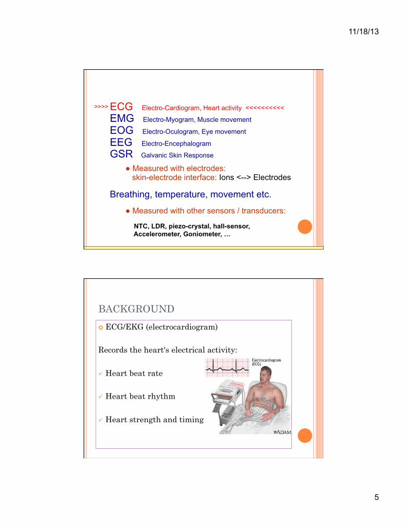
ECG Electro-Cardiogram, Heart activity <<<<<<<<<<
EMG Electro-Myogram, Muscle movement
EOG Electro-Oculogram, Eye movement
EEG Electro-Encephalogram
GSR Galvanic Skin Response
● Measured with electrodes: skin-electrode interface: Ions <--> Electrodes
Breathing, temperature, movement etc.
● Measured with other sensors / transducers:
NTC, LDR, piezo-crystal, hall-sensor, Accelerometer, Goniometer, …
>>>>
BACKGROUND�
¢ ECG/EKG (electrocardiogram)
Records the heart's electrical activity:
ü Heart beat rate
ü Heart beat rhythm
ü Heart strength and timing

11/18/13
6
BACKGROUND�
ECG works mostly by detecting and ampl i fy ing the t iny potential changes on the skin that are caused when the electrical signal in the heart muscle is charged and spread during each heart beat. This is detected as tiny rises and fal ls in the voltage between two electrodes placed either side of the heart.
BACKGROUND �
¢ The heart's electrical system:
¢ Sinoatrial(SA) node
¢ Atrioventricular(AV) node
¢ His-Purkinje system

11/18/13
7
BACKGROUND �
P wave: signal spread from SA node to make the atria contract.
P-Q Segment: signal arrives AV node stay for a instant to allow the ventricle to be filled with blood.
Q wave :After the Bundle of His the signal is divided into two branches and run through the septum.
R,S wave: Left and right ventricle contraction are marked by the R,S wave.
T wave: ventricle relaxing Schematic representation of normal ECG
ECG SIGNAL�
¢ ECG bio-signal typical specifications:
Ø low differential voltage from 0.4 to 3 mV Ø high common-mode rejection ratio level Ø low frequency range Ø high noise

11/18/13
8
ECG SIGNAL�
l Artifacts (disturbances) can have many causes. Common causes are:
p Movement
Baseline drift
Sudden movement
ECG SIGNAL�
p Electrical interference
àFrom a nearby electrical appliance. A typical example is a 100 Hz background distortion from fluorescent lights. To be confused with atrial fibrillation.

11/18/13
9
ECG ELECTRODE�
¢ Lead u The signal recorded as the difference between
two potentials on the body surface is called an "ECG lead". Each lead is said to look at the heart from a different angle.
ELECTRODE �
¢ Lead position
Lead III Lead 12

11/18/13
10
ECG ELECTRODE �
① Limb Leads (Bipolar) ② Chest Leads (Unipolar) ③
Augmented Limb Leads (Unipolar)
Wet, dry and insulating…
A typical surface electrode used for ECG recording is made of Ag/AgCl, as shown on right Figure . The disposable electrodes are attached to the patients’ skin and can be easily removed.
First, to make sure we know where the heart is …

11/18/13
11
Sensing the heart’s electrical activity via electrodes (contacts placed on the surface of the body)
Sensing the heart’s electrical activity via electrodes (contacts placed on the surface of the body)
Note: anatomical orientation is from the subject’s perspective:

11/18/13
12
The basic four limb electrodes:
right arm
left leg
left arm
right leg
electrical polarity:
neutral or ground
negative
positive (manipulated by the EKG machine)
right arm
left leg
left arm
right leg
electrical polarity:
neutral or ground
negative
positive
Lead I (toward left)

11/18/13
13
for any given viewing (positive) electrode:
An approaching train of muscle fiber depolarizations (or repolarizations moving away) is seen as an upward trace on the recording (opposite movement = downward trace)
Interpreting the view from an electrode
Note: the normal average direction for the heart’s electrical activity is from the upper right, in the right atrium, to the lower left.
P
Q
R
S
T
(This particular tracing does not show a Q wave, a downward wave just before the R wave.)
The main, typical waves of an EKG.

11/18/13
14
ATRIA: depol-pause-repol (atrial repolarization is obscured by ventricular depolarization)
P
VENTRICLES: depol-pause-repolarize
Q
R
S
T
QRS complex

11/18/13
15
1 mm = 0.1 mV
1 cm = 1 mV
1 mm = 0.04 seconds
5 mm = 0.20 seconds 25 mm/second
Standard calibration of EKG recordings
Electrocardiograph Block Diagram

11/18/13
16
Characteristics of ECG signals
the actual signal value will be ~0.4mV in an offset environment of 300mV.
SOURCES OF NOISE IN ECG SIGNALS
¢ Baseline wander (low frequency noise) ¢ Power line interference ( 60Hz noise from power
lines) ¢ Muscle noise (This noise is very difficult to remove
as it is in the same region as the actual signal. It is usually corrected in software.)
¢ Other interference (i.e., radio frequency noise from other equipment)

11/18/13
17
REMOVAL OF COMMON MODE NOISE
¢ Use instrumentation amplifiers with very high
common mode rejection ratios on the order of 100dB
¢ Drive the patient body with an inverted common mode signal.
¢ Apply software algorithms after acquisition for the removal of noise
Our EKG Analog Front End Circuit

11/18/13
18
Instrumentation Amplifier
• High Common Mode Rejection– 120dB minimum • Settable gain of 1 to 1000x, controlled by R3 • Low voltage, Single supply
Virtual Ground Circuit
• Virtual Ground– 3.3v/2 • allows signals 0-3.3v swing

11/18/13
19
Band Pass filter ~1 Hz to ~40 Hz
60 Hz Notch filter and output buffer

11/18/13
20
Our EKG Analog Front End Circuit
THIS WEEK’S LAB 7
¢ Build an Analog Front End circuit for an ECG ¢ Test it ¢ Connect it to the FriendlyArm ADC
Next Week– display traces on LCD and calibrate To Standard Grid Add digital processing to clean up signal Final week– Add diagnostic signal processing routines

11/18/13
21
Our EKG Analog Front End Circuit
Our EKG Analog Front End Circuit

11/18/13
22