ece 4110 internetwork programming lab 8: setting up a...
TRANSCRIPT
1
ECE 4110 Internetwork Programming Lab 8: Setting up a Network Using VRFs, VLAN, NAT, OSPF
Group Number: _________________________ Member Names: _________________________ _________________________
Date Issued: November 22, 2010 Turn-in Due: December 3, 2010 Last Edited: November 20, 2010 This lab requires that you use one of three setups. If a signup sheet has been posted, you must sign up in advance on the lab door. You may reserve each setup for no more than 2 hours at a time. YOU MUST USE THE SAME SETUP EACH TIME YOU WORK ON THIS LAB. A TA must be present for two check-offs of this lab. Also, it would be useful to bring your ECE4110 Lab5 and Lab6 documentation to help you in configuring/troubleshooting the network. Please read the entire lab before you show up to start working on it. Fill this blank in after you make your reservation: We signed up for PLAYSTATION #: _______________
Lab Goals
• Configure switches and routers on a network • Understand VLANs and inter-VLAN routing • Understand VRFs (VPN Routing and Forwarding Instances) • Undertand NAT • Understand OSPF processes on a router

2
Prelab Questions:
1. What is the purpose of creating VLANs on a switch? 2. How can the devices connected to switch ports associated with multiple VLAN
communicate?
3. What is NAT and how it is used in a network?
4. What are some advantages of configuring routing protocols instead of static routes? Check-off Point 0: TA has to make sure that routers are properly reloaded.
3
Lab Scenario
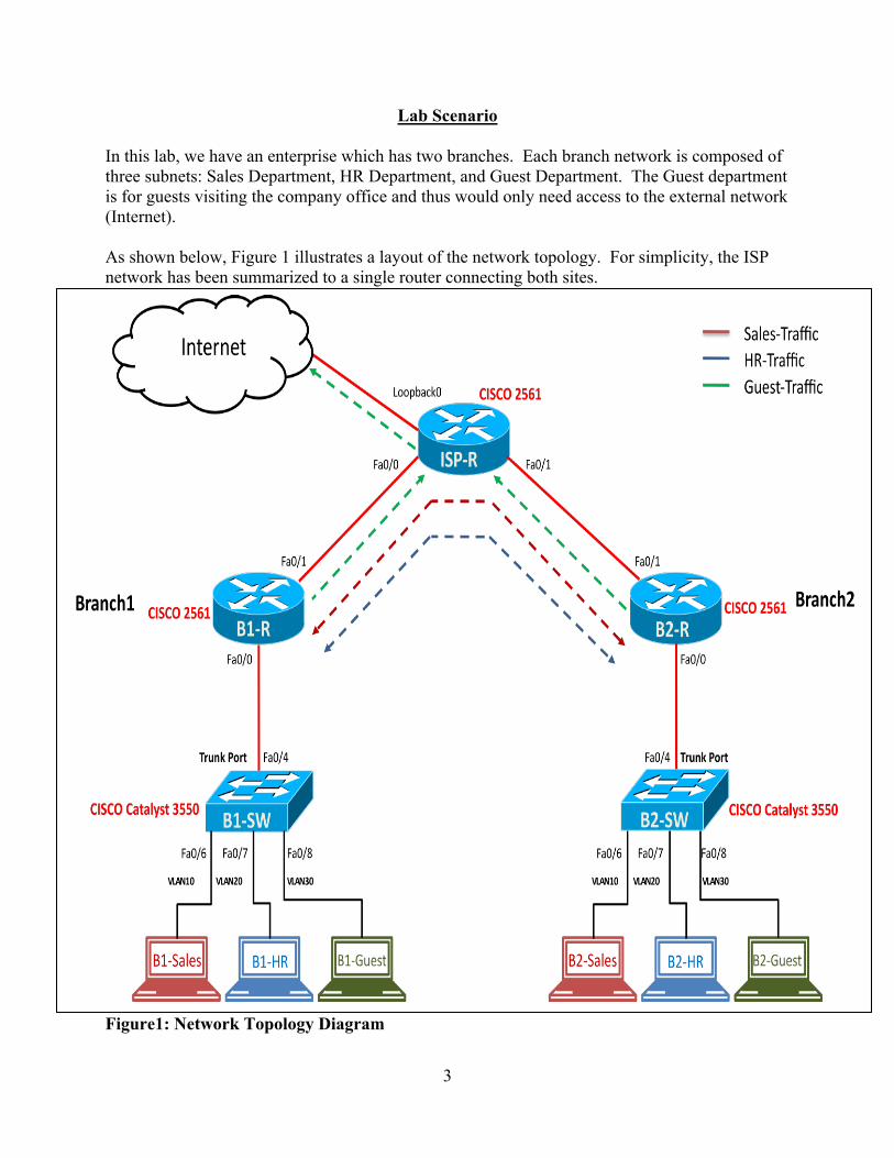
In this lab, we have an enterprise which has two branches. Each branch network is composed of three subnets: Sales Department, HR Department, and Guest Department. The Guest department is for guests visiting the company office and thus would only need access to the external network (Internet). As shown below, Figure 1 illustrates a layout of the network topology. For simplicity, the ISP network has been summarized to a single router connecting both sites. Figure1: Network Topology Diagram
4
Network Setup Requirements: The company would like to enforce the following policies on their network: Policy1: Devices on different VLANs are not allowed to communicate. For example, Sales end-hosts cannot communicate with HR end-hosts within a branch or across branches. Policy2: Devices on Sales and HR network are not allowed to access external network (Internet). Policy3: Guest network devices are only allowed to access external network (Internet). Policy4: Both Sales and HR end-hosts need to be able to communicate with their peer end-hosts in the remote branch.
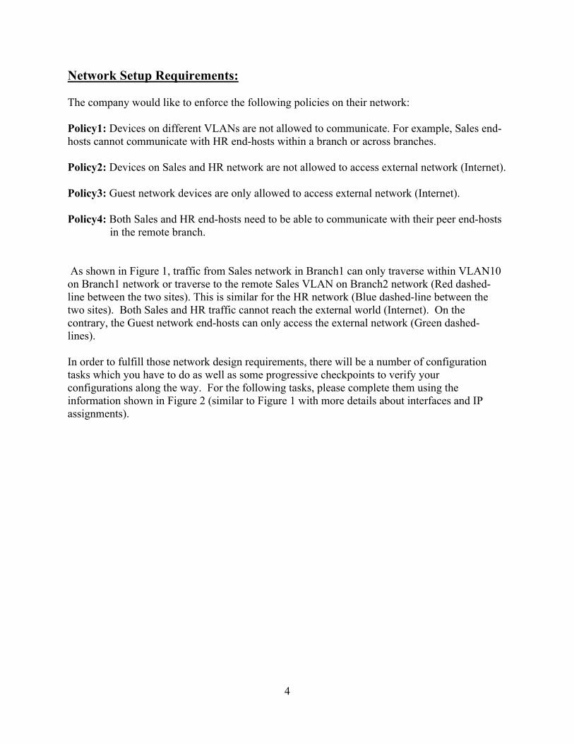
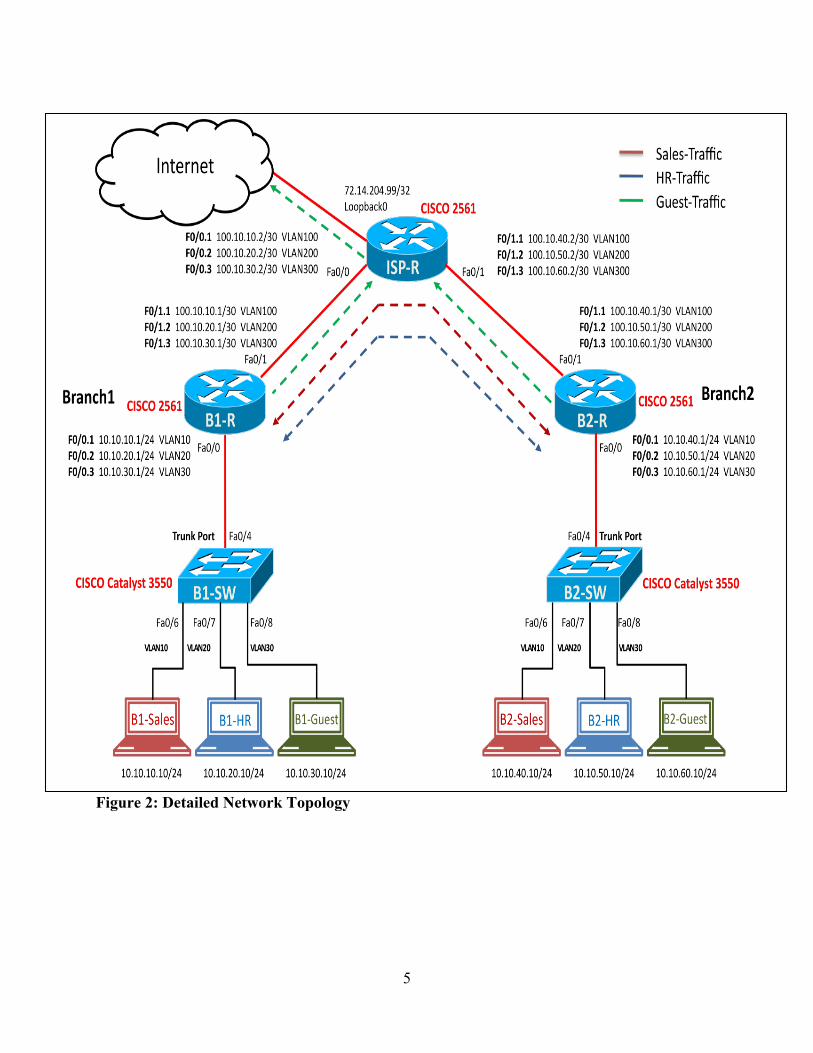
As shown in Figure 1, traffic from Sales network in Branch1 can only traverse within VLAN10 on Branch1 network or traverse to the remote Sales VLAN on Branch2 network (Red dashed-line between the two sites). This is similar for the HR network (Blue dashed-line between the two sites). Both Sales and HR traffic cannot reach the external world (Internet). On the contrary, the Guest network end-hosts can only access the external network (Green dashed-lines). In order to fulfill those network design requirements, there will be a number of configuration tasks which you have to do as well as some progressive checkpoints to verify your configurations along the way. For the following tasks, please complete them using the information shown in Figure 2 (similar to Figure 1 with more details about interfaces and IP assignments).
5
Figure 2: Detailed Network Topology
6
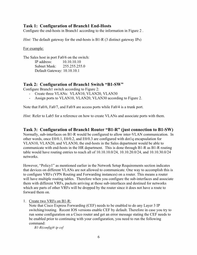
Task 1: Configuration of Branch1 End-Hosts Configure the end-hosts in Branch1 according to the information in Figure 2 . Hint: The default gateway for the end-hosts is B1-R (3 distinct gateway IPs) For example: The Sales host in port Fa0/6 on the switch:
IP address: 10.10.10.10 Subnet Mask: 255.255.255.0 Default Gateway: 10.10.10.1
Task 2: Configuration of Branch1 Switch “B1-SW” Configure Branch1 switch according to Figure 2:
- Create three VLANs: VLAN10, VLAN20, VLAN30 - Assign ports to VLAN10, VLAN20, VLAN30 according to Figure 2.
Note that Fa0/6, Fa0/7, and Fa0/8 are access ports while Fa0/4 is a trunk port. Hint: Refer to Lab5 for a reference on how to create VLANs and associate ports with them. Task 3: Configuration of Branch1 Router “B1-R” (just connection to B1-SW) Normally, sub-interfaces on B1-R would be configured to allow inter-VLAN communication. In other words, once E0/0.1, E0/0.2, and E0/0.3 are configured with dot1q encapsulation for VLAN10, VLAN20, and VLAN30, the end-hosts in the Sales department would be able to communicate with end-hosts in the HR department. This is done through B1-R as B1-R routing table would have routing entries to reach all of 10.10.10.0/24, 10.10.20.0/24, and 10.10.30.0/24 networks. However, “Policy1” as mentioned earlier in the Network Setup Requirements section indicates that devices on different VLANs are not allowed to communicate. One way to accomplish this is to configure VRFs (VPN Routing and Forwarding instances) on a router. This means a router will have multiple routing tables. Therefore when you configure the sub-interfaces and associate them with different VRFs, packets arriving at those sub-interfaces and destined for networks which are parts of other VRFs will be dropped by the router since it does not have a route to forward them on. 1. Create two VRFs on B1-R:
Note that Cisco Express Forwarding (CEF) needs to be enabled to do any Layer 3 IP switching/routing. Recent IOS versions enable CEF by default. Therefore in case you try to run some configuration on a Cisco router and get an error message stating the CEF needs to be enabled prior to continuing with your configuration, you need to run the following command: B1-R(config)# ip cef
7
By default, a router has only one routing table, referred to as the “Global” vrf. In this task, you will create two additional VRFs on B1-R named “RED” and “BLUE” as shown below.
B1-R(config)# ip vrf RED B1-R(config)# description Sales-Traffic B1-R(config)# rd 1:1 B1-R(config)# ip vrf BLUE B1-R(config)# description HR-Traffic B1-R(config)# rd 2:2
2. Create the sub-interfaces connecting B1-R to B1-SW:
You need to configure E0/0.1, E0/0.2, and E0/0.3 on B1-R as follows:
E0/0.1 is associated with vrf RED E0/0.2 is associated with vrf BLUE E0/0.3 is associated with the Global vrf (default table) So, the configuration commands would be:
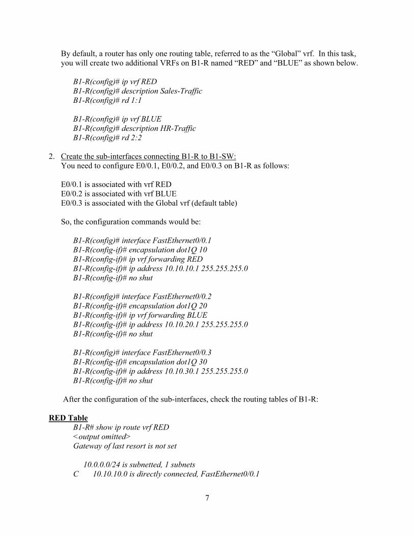
B1-R(config)# interface FastEthernet0/0.1 B1-R(config-if)# encapsulation dot1Q 10 B1-R(config-if)# ip vrf forwarding RED B1-R(config-if)# ip address 10.10.10.1 255.255.255.0 B1-R(config-if)# no shut B1-R(config)# interface FastEthernet0/0.2 B1-R(config-if)# encapsulation dot1Q 20 B1-R(config-if)# ip vrf forwarding BLUE B1-R(config-if)# ip address 10.10.20.1 255.255.255.0 B1-R(config-if)# no shut B1-R(config)# interface FastEthernet0/0.3 B1-R(config-if)# encapsulation dot1Q 30 B1-R(config-if)# ip address 10.10.30.1 255.255.255.0 B1-R(config-if)# no shut
After the configuration of the sub-interfaces, check the routing tables of B1-R: RED Table
B1-R# show ip route vrf RED <output omitted> Gateway of last resort is not set 10.0.0.0/24 is subnetted, 1 subnets C 10.10.10.0 is directly connected, FastEthernet0/0.1
8
BLUE Table
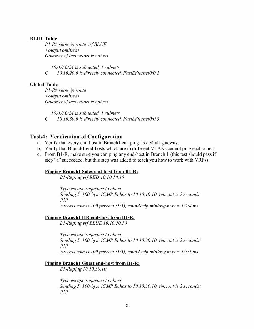
B1-R# show ip route vrf BLUE <output omitted> Gateway of last resort is not set 10.0.0.0/24 is subnetted, 1 subnets C 10.10.20.0 is directly connected, FastEthernet0/0.2
Global Table
B1-R# show ip route <output omitted> Gateway of last resort is not set 10.0.0.0/24 is subnetted, 1 subnets C 10.10.30.0 is directly connected, FastEthernet0/0.3
Task4: Verification of Configuration
a. Verify that every end-host in Branch1 can ping its default gateway. b. Verify that Branch1 end-hosts which are in different VLANs cannot ping each other. c. From B1-R, make sure you can ping any end-host in Branch 1 (this test should pass if
step “a” succeeded, but this step was added to teach you how to work with VRFs) Pinging Branch1 Sales end-host from B1-R:
B1-R#ping vrf RED 10.10.10.10 Type escape sequence to abort. Sending 5, 100-byte ICMP Echos to 10.10.10.10, timeout is 2 seconds: !!!!! Success rate is 100 percent (5/5), round-trip min/avg/max = 1/2/4 ms
Pinging Branch1 HR end-host from B1-R: B1-R#ping vrf BLUE 10.10.20.10 Type escape sequence to abort. Sending 5, 100-byte ICMP Echos to 10.10.20.10, timeout is 2 seconds: !!!!! Success rate is 100 percent (5/5), round-trip min/avg/max = 1/3/5 ms
Pinging Branch1 Guest end-host from B1-R:
B1-R#ping 10.10.30.10 Type escape sequence to abort. Sending 5, 100-byte ICMP Echos to 10.10.30.10, timeout is 2 seconds: !!!!!
9
Success rate is 100 percent (5/5), round-trip min/avg/max = 1/2/4 ms
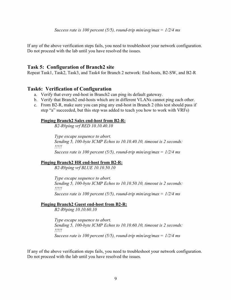
If any of the above verification steps fails, you need to troubleshoot your network configuration. Do not proceed with the lab until you have resolved the issues. Task 5: Configuration of Branch2 site Repeat Task1, Task2, Task3, and Task4 for Branch 2 network: End-hosts, B2-SW, and B2-R Task6: Verification of Configuration
a. Verify that every end-host in Branch2 can ping its default gateway. b. Verify that Branch2 end-hosts which are in different VLANs cannot ping each other. c. From B2-R, make sure you can ping any end-host in Branch 2 (this test should pass if
step “a” succeeded, but this step was added to teach you how to work with VRFs) Pinging Branch2 Sales end-host from B2-R:
B2-R#ping vrf RED 10.10.40.10 Type escape sequence to abort. Sending 5, 100-byte ICMP Echos to 10.10.40.10, timeout is 2 seconds: !!!!! Success rate is 100 percent (5/5), round-trip min/avg/max = 1/2/4 ms
Pinging Branch2 HR end-host from B2-R: B2-R#ping vrf BLUE 10.10.50.10 Type escape sequence to abort. Sending 5, 100-byte ICMP Echos to 10.10.50.10, timeout is 2 seconds: !!!!! Success rate is 100 percent (5/5), round-trip min/avg/max = 1/2/4 ms
Pinging Branch2 Guest end-host from B2-R: B2-R#ping 10.10.60.10 Type escape sequence to abort. Sending 5, 100-byte ICMP Echos to 10.10.60.10, timeout is 2 seconds: !!!!! Success rate is 100 percent (5/5), round-trip min/avg/max = 1/2/4 ms
If any of the above verification steps fails, you need to troubleshoot your network configuration. Do not proceed with the lab until you have resolved the issues.
10
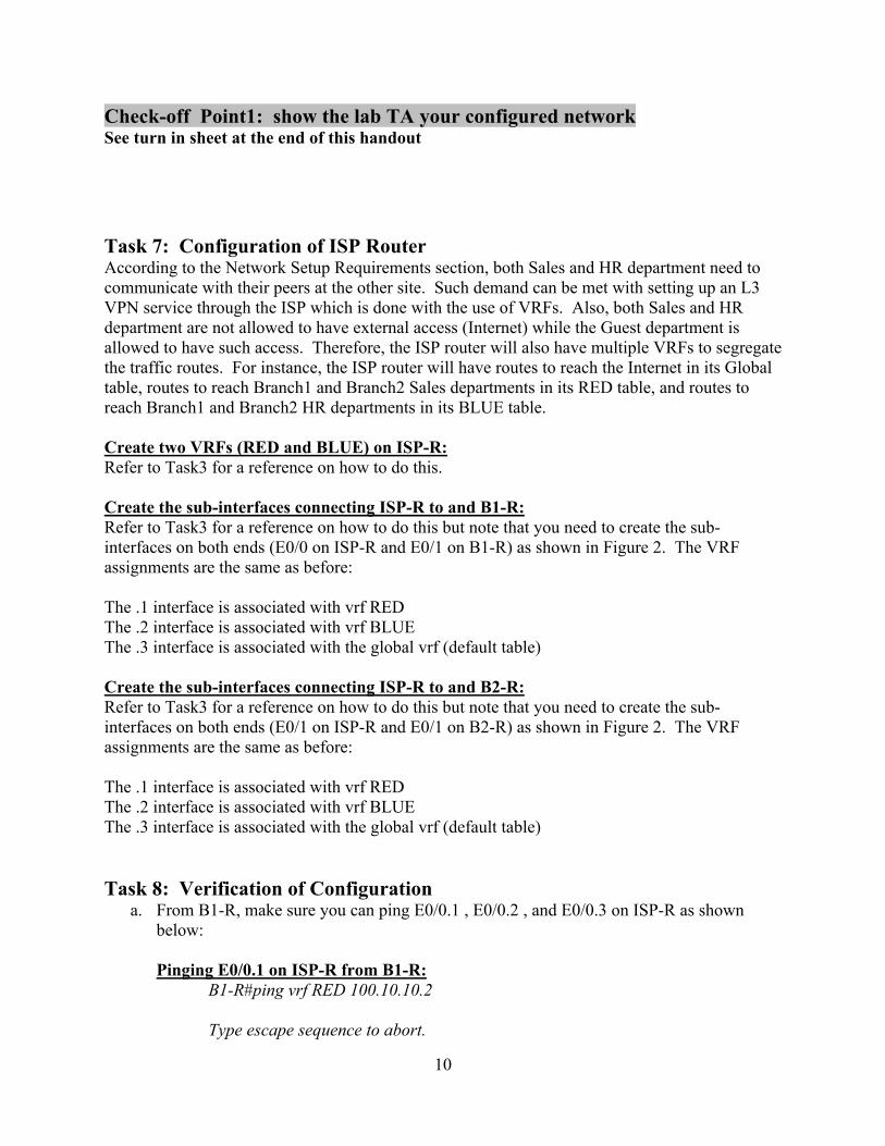
Check-off Point1: show the lab TA your configured network See turn in sheet at the end of this handout Task 7: Configuration of ISP Router According to the Network Setup Requirements section, both Sales and HR department need to communicate with their peers at the other site. Such demand can be met with setting up an L3 VPN service through the ISP which is done with the use of VRFs. Also, both Sales and HR department are not allowed to have external access (Internet) while the Guest department is allowed to have such access. Therefore, the ISP router will also have multiple VRFs to segregate the traffic routes. For instance, the ISP router will have routes to reach the Internet in its Global table, routes to reach Branch1 and Branch2 Sales departments in its RED table, and routes to reach Branch1 and Branch2 HR departments in its BLUE table. Create two VRFs (RED and BLUE) on ISP-R: Refer to Task3 for a reference on how to do this. Create the sub-interfaces connecting ISP-R to and B1-R: Refer to Task3 for a reference on how to do this but note that you need to create the sub-interfaces on both ends (E0/0 on ISP-R and E0/1 on B1-R) as shown in Figure 2. The VRF assignments are the same as before: The .1 interface is associated with vrf RED The .2 interface is associated with vrf BLUE The .3 interface is associated with the global vrf (default table) Create the sub-interfaces connecting ISP-R to and B2-R: Refer to Task3 for a reference on how to do this but note that you need to create the sub-interfaces on both ends (E0/1 on ISP-R and E0/1 on B2-R) as shown in Figure 2. The VRF assignments are the same as before: The .1 interface is associated with vrf RED The .2 interface is associated with vrf BLUE The .3 interface is associated with the global vrf (default table) Task 8: Verification of Configuration
a. From B1-R, make sure you can ping E0/0.1 , E0/0.2 , and E0/0.3 on ISP-R as shown below: Pinging E0/0.1 on ISP-R from B1-R:
B1-R#ping vrf RED 100.10.10.2 Type escape sequence to abort.

11
Sending 5, 100-byte ICMP Echos to 100.10.10.2, timeout is 2 seconds: !!!!! Success rate is 100 percent (5/5), round-trip min/avg/max = 1/2/4 ms
Pinging E0/0.2 on ISP-R from B1-R: B1-R#ping vrf BLUE 100.10.20.2 Type escape sequence to abort. Sending 5, 100-byte ICMP Echos to 100.10.20.2, timeout is 2 seconds: !!!!! Success rate is 100 percent (5/5), round-trip min/avg/max = 1/2/4 ms
Pinging E0/0.3 on ISP-R from B1-R: B1-R#ping 100.10.30.2 Type escape sequence to abort. Sending 5, 100-byte ICMP Echos to 100.10.30.2, timeout is 2 seconds: !!!!! Success rate is 100 percent (5/5), round-trip min/avg/max = 1/3/4 ms
b. From B2-R, make sure you can ping E0/1.1 , E0/1.2 , and E0/1.3 on ISP-R as shown
below: Pinging E0/1.1 on ISP-R from B2-R:
B2-R#ping vrf RED 100.10.40.2 Type escape sequence to abort. Sending 5, 100-byte ICMP Echos to 100.10.40.2, timeout is 2 seconds: !!!!! Success rate is 100 percent (5/5), round-trip min/avg/max = 1/2/4 ms
Pinging E0/1.2 on ISP-R from B2-R: B2-R#ping vrf BLUE 100.10.50.2 Type escape sequence to abort. Sending 5, 100-byte ICMP Echos to 100.10.50.2, timeout is 2 seconds: !!!!! Success rate is 100 percent (5/5), round-trip min/avg/max = 1/2/4 ms
Pinging E0/1.3 on ISP-R from B2-R: B2-R#ping 100.10.60.2 Type escape sequence to abort. Sending 5, 100-byte ICMP Echos to 100.10.60.2, timeout is 2 seconds: !!!!! Success rate is 100 percent (5/5), round-trip min/avg/max = 1/3/4 ms

12
If any of the above verification steps fails, you need to troubleshoot your network configuration. Do not proceed with the lab until you have resolved the issues. Task 9: Configure OSPF on B1-R, B2-R, and ISP-R Routers At this point, ISP-R only has information about directly connected routes such as B1-R WAN and B2-R WAN. ISP-R does not have any routes to B1-R LAN or B2-R LAN. Similarly, B1-R and B2-R only have information about directly connected routes and does not know how to reach the Internet. There are two options for the routers to learn about new routes: statically or dynamically. In this lab, we will enable OSPF on B1-R, B2-R, and ISP-R to learn the routes dynamically. The OSPF configuration is very similar to the OSPF configuration you did in a previous lab except to the part that every router will be running three OSPF processes:
1. One for the Global VRF 2. One for the RED VRF 3. One for the BLUE VRF
For example, B1-R OSPF can be configured as follows: OSPF process for RED vrf:
B1-R(config)# router ospf 1 vrf RED B1-R(config-route)# router-id 0.0.1.1 B1-R(config-route)# network 10.10.10.0 0.0.0.255 area 0 B1-R(config-route)# network 100.10.10.0 0.0.0.3 area 0
OSPF process for BLUE vrf:
B1-R(config)# router ospf 2 vrf BLUE B1-R(config-route)# router-id 0.0.1.2 B1-R(config-route)# network 10.10.20.0 0.0.0.255 area 0 B1-R(config-route)# network 100.10.20.0 0.0.0.3 area 0
OSPF process for Global table:
B1-R(config)# router ospf 3 B1-R(config-route)# router-id 0.0.1.3 B1-R(config-route)# network 100.10.30.0 0.0.0.3 area 0
If you noticed, B1-R advertised both 10.10.10.0/24 and 10.10.20.0/24 LANs to ISP-R because both Sales and HR departments need to communicate with their peers in Branch2 through ISP-R (L3 VPN connection). As for the Guest network, 10.10.30.0/24, B1-R did not advertise it since this network only need to access the external network (Internet). B1-R cannot advertise to the public a private address, so NAT will be configured on B1-R to address this later on in this lab.
13
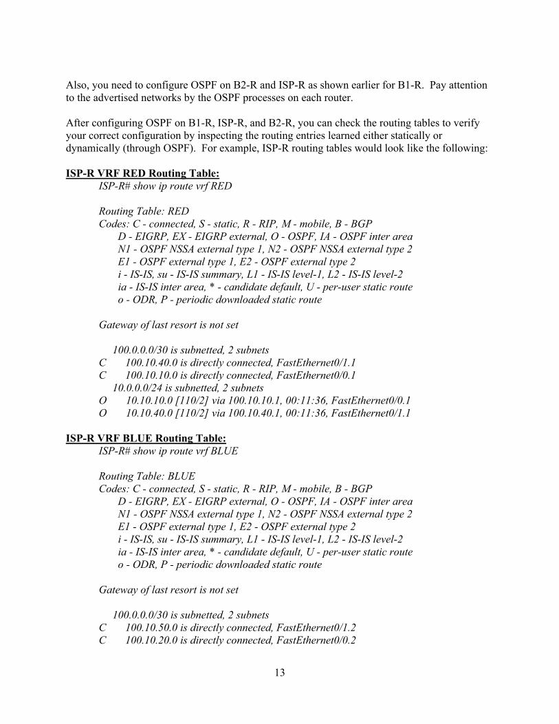
Also, you need to configure OSPF on B2-R and ISP-R as shown earlier for B1-R. Pay attention to the advertised networks by the OSPF processes on each router. After configuring OSPF on B1-R, ISP-R, and B2-R, you can check the routing tables to verify your correct configuration by inspecting the routing entries learned either statically or dynamically (through OSPF). For example, ISP-R routing tables would look like the following: ISP-R VRF RED Routing Table:
ISP-R# show ip route vrf RED Routing Table: RED Codes: C - connected, S - static, R - RIP, M - mobile, B - BGP D - EIGRP, EX - EIGRP external, O - OSPF, IA - OSPF inter area N1 - OSPF NSSA external type 1, N2 - OSPF NSSA external type 2 E1 - OSPF external type 1, E2 - OSPF external type 2 i - IS-IS, su - IS-IS summary, L1 - IS-IS level-1, L2 - IS-IS level-2 ia - IS-IS inter area, * - candidate default, U - per-user static route o - ODR, P - periodic downloaded static route Gateway of last resort is not set 100.0.0.0/30 is subnetted, 2 subnets C 100.10.40.0 is directly connected, FastEthernet0/1.1 C 100.10.10.0 is directly connected, FastEthernet0/0.1 10.0.0.0/24 is subnetted, 2 subnets O 10.10.10.0 [110/2] via 100.10.10.1, 00:11:36, FastEthernet0/0.1 O 10.10.40.0 [110/2] via 100.10.40.1, 00:11:36, FastEthernet0/1.1
ISP-R VRF BLUE Routing Table:
ISP-R# show ip route vrf BLUE Routing Table: BLUE Codes: C - connected, S - static, R - RIP, M - mobile, B - BGP D - EIGRP, EX - EIGRP external, O - OSPF, IA - OSPF inter area N1 - OSPF NSSA external type 1, N2 - OSPF NSSA external type 2 E1 - OSPF external type 1, E2 - OSPF external type 2 i - IS-IS, su - IS-IS summary, L1 - IS-IS level-1, L2 - IS-IS level-2 ia - IS-IS inter area, * - candidate default, U - per-user static route o - ODR, P - periodic downloaded static route Gateway of last resort is not set 100.0.0.0/30 is subnetted, 2 subnets C 100.10.50.0 is directly connected, FastEthernet0/1.2 C 100.10.20.0 is directly connected, FastEthernet0/0.2

14
10.0.0.0/24 is subnetted, 2 subnets O 10.10.20.0 [110/2] via 100.10.20.1, 00:11:17, FastEthernet0/0.2 O 10.10.50.0 [110/2] via 100.10.50.1, 00:11:17, FastEthernet0/1.2
ISP-R Global Routing Table:
ISP-R# show ip route Codes: C - connected, S - static, R - RIP, M - mobile, B - BGP D - EIGRP, EX - EIGRP external, O - OSPF, IA - OSPF inter area N1 - OSPF NSSA external type 1, N2 - OSPF NSSA external type 2 E1 - OSPF external type 1, E2 - OSPF external type 2 i - IS-IS, su - IS-IS summary, L1 - IS-IS level-1, L2 - IS-IS level-2 ia - IS-IS inter area, * - candidate default, U - per-user static route o - ODR, P - periodic downloaded static route Gateway of last resort is not set 100.0.0.0/30 is subnetted, 2 subnets C 100.10.60.0 is directly connected, FastEthernet0/1.3 C 100.10.30.0 is directly connected, FastEthernet0/0.3
Task 10: Verification of Configuration a. Verify that Sales end-host in Branch1 can ping Sales end-host in Branch2 b. Verify that HR end-host in Branch1 can ping HR end-host in Branch2
If any of the above verification steps fails, you need to troubleshoot your network configuration. Do not proceed with the lab until you have resolved the issues. Check-off Point2: show the lab TA your configured network See turn in sheet at the end of this handout Task 11: Add Route to the Internet on ISP-R, B1-R, and B2-R Typically, an ISP router will have routes to reach entities such as Google server, MSN server, CNN server, etc. However, to simplify the lab setup, a route to a Google server from the ISP router will be emulated using a loopback interface on ISP-R. A loopback interface is a logical interface internal to a router and it is not connected to any device. By default, a loopback interface is enabled on a Cisco router and in order to use it, it needs to be configured with an IP address. In our lab, the loopback interface will be assigned a public IP address representing a public search engine server. Illustrated below are the commands used to configure the loopback interface on ISP-R:
ISP-R(config)# interface loopback 0 ISP-R(config-if)# ip address 72.14.204.99 255.255.255.255

15
Next, you need to configure a static default route on both B1-R and B2-R pointing to ISP-R. This way, packets arriving at B1-R and B2-R from the Guest network and destined to a public address will be routed to ISP-R . Adding a default route on B1-R can be done as follows:
B1-R(config)# ip route 0.0.0.0 0.0.0.0 100.10.30.2 (where 100.10.30.2 is the next-hop IP address, E0/0.3 address on ISP-R)
Task 12: Verification of Configuration
1. Pinging 72.14.204.99 from both B1-R and B2-R should succeed From B1-R:
B1-R#ping 72.14.204.99 Type escape sequence to abort. Sending 5, 100-byte ICMP Echos to 72.14.204.99, timeout is 2 seconds: !!!!! Success rate is 100 percent (5/5), round-trip min/avg/max = 1/3/4 ms
From B2-R:
B2-R#ping 72.14.204.99 Type escape sequence to abort. Sending 5, 100-byte ICMP Echos to 72.14.204.99, timeout is 2 seconds: !!!!! Success rate is 100 percent (5/5), round-trip min/avg/max = 1/2/4 ms
2. Pinging 72.14.204.99 from either Guest end-hosts should fail
From B1-Guest:
B1-Guest#ping 72.14.204.99 Type escape sequence to abort. Sending 5, 100-byte ICMP Echos to 72.14.204.99, timeout is 2 seconds: ..... Success rate is 0 percent (0/5)
From B2-Guest:
B2-Guest#ping 72.14.204.99 Type escape sequence to abort. Sending 5, 100-byte ICMP Echos to 72.14.204.99, timeout is 2 seconds: ..... Success rate is 0 percent (0/5)
16
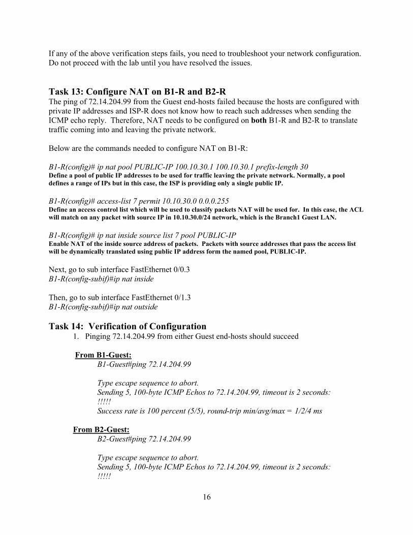
If any of the above verification steps fails, you need to troubleshoot your network configuration. Do not proceed with the lab until you have resolved the issues. Task 13: Configure NAT on B1-R and B2-R The ping of 72.14.204.99 from the Guest end-hosts failed because the hosts are configured with private IP addresses and ISP-R does not know how to reach such addresses when sending the ICMP echo reply. Therefore, NAT needs to be configured on both B1-R and B2-R to translate traffic coming into and leaving the private network. Below are the commands needed to configure NAT on B1-R: B1-R(config)# ip nat pool PUBLIC-IP 100.10.30.1 100.10.30.1 prefix-length 30 Define a pool of public IP addresses to be used for traffic leaving the private network. Normally, a pool defines a range of IPs but in this case, the ISP is providing only a single public IP. B1-R(config)# access-list 7 permit 10.10.30.0 0.0.0.255 Define an access control list which will be used to classify packets NAT will be used for. In this case, the ACL will match on any packet with source IP in 10.10.30.0/24 network, which is the Branch1 Guest LAN. B1-R(config)# ip nat inside source list 7 pool PUBLIC-IP Enable NAT of the inside source address of packets. Packets with source addresses that pass the access list will be dynamically translated using public IP address form the named pool, PUBLIC-IP. Next, go to sub interface FastEthernet 0/0.3 B1-R(config-subif)#ip nat inside Then, go to sub interface FastEthernet 0/1.3 B1-R(config-subif)#ip nat outside Task 14: Verification of Configuration
1. Pinging 72.14.204.99 from either Guest end-hosts should succeed
From B1-Guest: B1-Guest#ping 72.14.204.99 Type escape sequence to abort. Sending 5, 100-byte ICMP Echos to 72.14.204.99, timeout is 2 seconds: !!!!! Success rate is 100 percent (5/5), round-trip min/avg/max = 1/2/4 ms
From B2-Guest: B2-Guest#ping 72.14.204.99 Type escape sequence to abort. Sending 5, 100-byte ICMP Echos to 72.14.204.99, timeout is 2 seconds: !!!!!
17
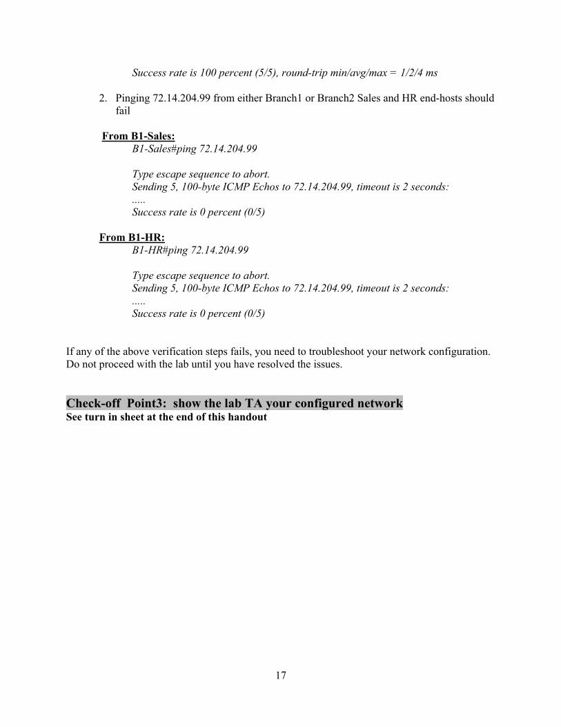
Success rate is 100 percent (5/5), round-trip min/avg/max = 1/2/4 ms
2. Pinging 72.14.204.99 from either Branch1 or Branch2 Sales and HR end-hosts should fail
From B1-Sales:
B1-Sales#ping 72.14.204.99 Type escape sequence to abort. Sending 5, 100-byte ICMP Echos to 72.14.204.99, timeout is 2 seconds: ..... Success rate is 0 percent (0/5)
From B1-HR: B1-HR#ping 72.14.204.99 Type escape sequence to abort. Sending 5, 100-byte ICMP Echos to 72.14.204.99, timeout is 2 seconds: ..... Success rate is 0 percent (0/5)
If any of the above verification steps fails, you need to troubleshoot your network configuration. Do not proceed with the lab until you have resolved the issues. Check-off Point3: show the lab TA your configured network See turn in sheet at the end of this handout
18
ECE 4110 Internetwork Programming Turn in sheet
Lab 8: Setting up a Network Using VRFs, VLAN, NAT, OSPF
Group Number: ________ Member Names: _________________________ _________________________ Date: _____________________ Check-off Point1: show the lab TA Successful ping of B1-Sales from B1-R : ___________________________ Successful ping of B1-HR from B1-R : ___________________________ Successful ping of B1-Guest from B1-R : ___________________________ Successful ping of B2-Sales from B2-R : ___________________________ Successful ping of B2-HR from B2-R : ___________________________ Successful ping of B2-Guest from B2-R : ___________________________ TA Signature _______________________ DATE ______________________ Check-off Point2: show the lab TA Successful ping of B2-Sales from B1-Sales : ________________ Successful ping of B2-HR from B1-HR : ________________ TA Signature _______________________ DATE ______________________ Check-off Point3: show the lab TA Successful ping of 72.14.204.99 from B1-Guest and B2-Guest : ________________________ Failed ping of 72.14.204.99 from B1-Sales/B2-Sales/B1-HR/B2-HR : ________________ TA Signature _______________________ DATE ______________________

19
Turn-in List
1. The turn in sheet from the back of the lab (this sheet) 2. Nine Screenshots: Routing tables for the three routers (3 tables per router: Global
Table, RED Table, and BLUE Table)