ebook: powering wireless networks
TRANSCRIPT

Powering wireless networks

Chapter 1: Introduction 2
Elements of power To understand how wireless communication networks are powered, you need to begin with the basics—which really haven’t changed all that much since Thomas Edison lit up Manhattan’s Financial District (NYC) on September 4, 1882. Sure, we’ve seen a lot of refinements, improvements and safety measures since then, but the principles of power generation and distribution still apply.
If you want to prepare your networks to meet the power challenges of tomorrow, take a few minutes for this quick refresher on Power 101.
Contents
Introduction 31
Elements of power 42
Powering today’s macro site 123
PowerShift® Macro 164
Powering small cell metro networks 205
PowerShift® Metro 246
Conclusion 287

Chapter 1: Introduction 3
Introduction Putting power in contextEvery year, our reliance on always-on technology grows. We expect to be able
to place a call or surf the internet with our cell phones at any time, under any
circumstances. However, the electrical infrastructure that powers our wireless
networks has not kept pace with the demand for more macro cells and small cells.
The challenge goes deeper than powering additional cell sites. The architectures of
cellular access are changing dramatically. Customer demand is pushing 5G rollouts
which, in turn, require more RF equipment. Additional radios, more frequencies and
increasing use of remote radio units, plus an entire small cell layer that still needs to
be built out are pushing outdated power systems to the brink.
What’s at stake from a business perspective? Plenty. A reliable power infrastructure
has significant implications for both cost and revenue. Running power to thousands
of small cells will be expensive. Cutting cost by even a point or two can generate
major savings, as can reducing deployment times by a day or two. On the revenue
side, we know the effect that network outages have on churn rates. With the vast
majority of cell sites relying on older power grids for primary power, the need for
reliable backup power is more important than ever.
Welcome to the intersection of now and next To keep pace with the changes and, more importantly, to satisfy user expectations
of 24/7 availability, mobile operators need to re-evaluate all aspects of their power
infrastructure. That means taking stock of where we are from a solution standpoint,
where we need to be, and developing a cohesive, future-capable strategy to get us
from here to there.
That’s why CommScope has developed this ebook, to help keep you out in front.
Here, you’ll find the “what,” “why” and “how” to help guide your power decisions
as you navigate what’s next. We’ve broken it down into easy-to-digest chapters and
sections that walk you through the key issues of powering your macro and small cell
networks. Along the way, we added the CommScope innovations designed to help you
realize the more efficient, future-ready power solutions needed to keep you and your
networks moving forward.

Chapter 2: Elements of power 4
Elements of power To understand how wireless communication networks are powered, you need to begin with the basics—which really haven’t changed all that much since Thomas Edison lit up Manhattan’s Financial District (NYC) on September 4, 1882. Sure, we’ve seen a lot of refinements, improvements and safety measures since then, but the principles of power generation and distribution still apply.
Thomas Edison’s Pearl Street Station was the first commercial central power plant in the United States. It was located in the Financial District of Manhattan (New York City). Fired by coal and powered by six dynamos, it came on line September 4, 1882 and served an initial load of 400 lamps at 82 customers.
Chapter 2: Elements of power 5
DID YOU KNOW? In the late 1800s, Nikola Tesla was sure
he could transmit electricity wirelessly over long distances—either via a series of strategically positioned towers (above) or suspended balloons. He obviously failed,
but that’s a story for another time.
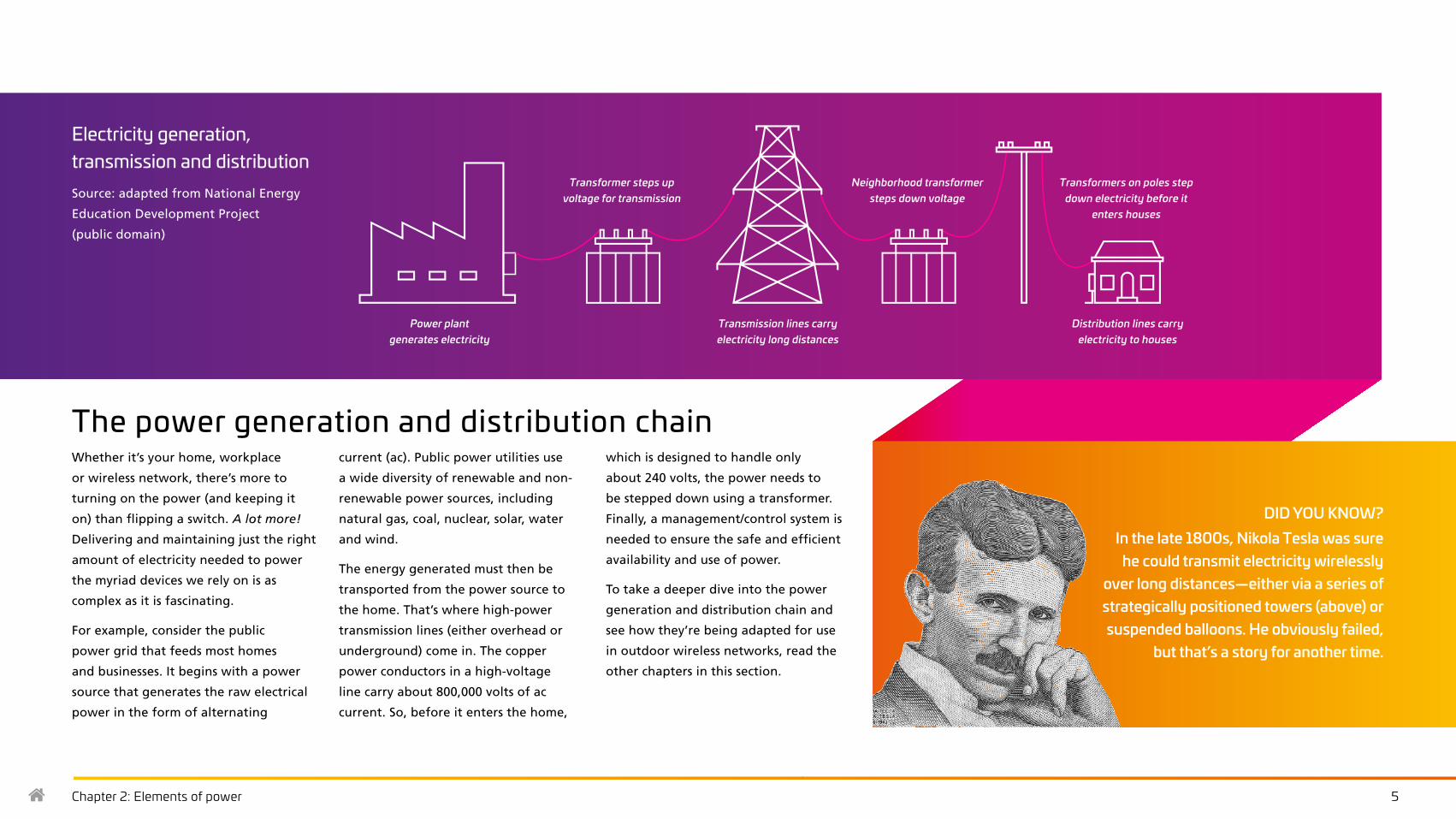
The power generation and distribution chain Whether it’s your home, workplace
or wireless network, there’s more to
turning on the power (and keeping it
on) than flipping a switch. A lot more!
Delivering and maintaining just the right
amount of electricity needed to power
the myriad devices we rely on is as
complex as it is fascinating.
For example, consider the public
power grid that feeds most homes
and businesses. It begins with a power
source that generates the raw electrical
power in the form of alternating
current (ac). Public power utilities use
a wide diversity of renewable and non-
renewable power sources, including
natural gas, coal, nuclear, solar, water
and wind.
The energy generated must then be
transported from the power source to
the home. That’s where high-power
transmission lines (either overhead or
underground) come in. The copper
power conductors in a high-voltage
line carry about 800,000 volts of ac
current. So, before it enters the home,
which is designed to handle only
about 240 volts, the power needs to
be stepped down using a transformer.
Finally, a management/control system is
needed to ensure the safe and efficient
availability and use of power.
To take a deeper dive into the power
generation and distribution chain and
see how they’re being adapted for use
in outdoor wireless networks, read the
other chapters in this section.
Power plant generates electricity
Transformer steps up voltage for transmission
Electricity generation, transmission and distributionSource: adapted from National Energy
Education Development Project
(public domain)
Transmission lines carry electricity long distances
Neighborhood transformer steps down voltage
Distribution lines carry electricity to houses
Transformers on poles step down electricity before it
enters houses
Chapter 2: Elements of power 6
Power sources for wireless networksWhen the grid isn’t enough It’s important to note that, in most cases, outdoor wireless networks use the public
power grid as their primary source of electricity. Access to power drops is readily
available and the cost per kilowatt is reasonable.
The challenge with the public power grid, however, is age and reliability. Each year,
power outages affect every city in every country across the globe. When the grid
is down, so is everything attached to it, including macro cell sites, small cells and
DAS systems. Outages don’t affect just personal and business communications. They
cripple public safety and first responder providers and they affect smart city services
and a host of other critical applications.
So, while tapping the power grid for your primary source of power is usually fine, it is
not enough. Provisioning your networks with a safe, reliable and cost-efficient power
backup system is vital. The following overview highlights some of the most common
and emerging technologies for supplying backup power to wireless networks.
There are critical cases, especially with small cell networks and DAS networks, where tapping into the power grid may not be the safest or most cost-effective solution. We discuss an alternative solution for those instances later on.
Lead-acid batteriesThese are commonly used as backups
for telecom power systems. They are
compact relative to their output and are
similar to the kind you would find under
the hood of your car. They are available
in vented and valve-regulated forms.
Vented (also known as wet or flooded) batteriesVented batteries maintain a charge for
up to 20 years or longer. However, they
demand a lot of costly maintenance such
as water treatment, spill containment
and forced-air ventilation. These
drawbacks make them less suited to
remote cell base stations.
Valve-regulated lead-acid batteries (VRLAs) VRLAs are recombinant batteries,
which means oxygen and hydrogen
can recombine to prevent water loss.
Because they don’t need added water,
they are easier to ship, maintain and
install, making them the preferred
choice for cell site base station use.
Lithium-ion batteriesThese batteries are relatively new for
wireless telecom applications. They
are highly compact, about 50 percent
the volume of a comparable VRLA
battery. Unlike VRLA batteries, which
are composed of four 12 Vdc batteries
per string, lithium-ion batteries are
packaged in a single rack-mounted
module that provides –48 Vdc output.
Should an individual module fail, the
remaining modules will continue to
provide backup power.
NiCad batteriesThese are becoming popular as
backups for telecom power systems.
In general, NiCad batteries have a
lower temperature operating range
and have fewer (or no) battery cooling
requirements, lighter weight and
longer life.
Battery stringsPower capacity is directly related to the
size of the battery; but, rather than
spending more on larger batteries, we
can achieve the same boost to capacity
by adding more battery strings in
parallel, as opposed to adding them
in series. This safeguards against the
failure of an individual battery, which
would remove its string from the system
altogether. By connecting in parallel,
the spare capacity is already online and
ready to maintain the current for its
rated length of time. This configuration
also provides a convenient means of
maintaining the batteries. Often, these
strings will be installed with separate
disconnection breakers—making it
easier to locate failures and isolate
problems that could otherwise cripple
the entire system.
GeneratorsBatteries alone can maintain operations
for only a few hours. Longer ac service
interruptions require a longer-term
solution. Unlike batteries, generators
provide power by burning fuel, typically
diesel. Like batteries, there are different
types and configurations available.
Which one you install depends on
factors like space, cost and service
expectations.
Since they operate outside the cell
station’s internal dc system, generators
aren’t considered part of that system.
Because they supply the dc system’s
rectifiers with the ac power they need,
however, they’re a vital link in assuring
reliable operation. In the event the
station must switch from external power
to generator-supplied ac power, an
electrical device called a “transfer switch”
shunts the load to the generator.
Chapter 2: Elements of power 7
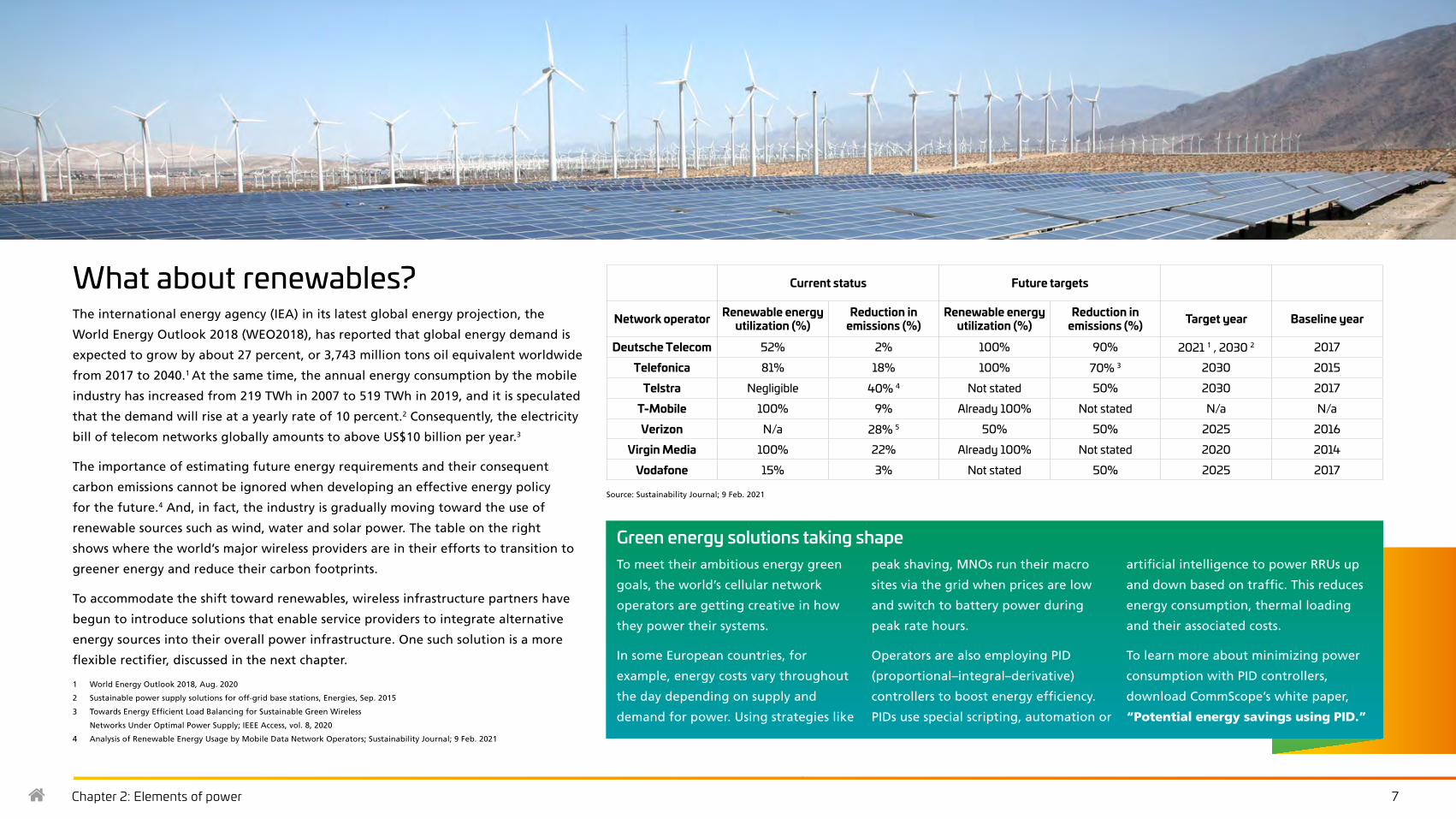
What about renewables?The international energy agency (IEA) in its latest global energy projection, the
World Energy Outlook 2018 (WEO2018), has reported that global energy demand is
expected to grow by about 27 percent, or 3,743 million tons oil equivalent worldwide
from 2017 to 2040.1 At the same time, the annual energy consumption by the mobile
industry has increased from 219 TWh in 2007 to 519 TWh in 2019, and it is speculated
that the demand will rise at a yearly rate of 10 percent.2 Consequently, the electricity
bill of telecom networks globally amounts to above US$10 billion per year.3
The importance of estimating future energy requirements and their consequent
carbon emissions cannot be ignored when developing an effective energy policy
for the future.4 And, in fact, the industry is gradually moving toward the use of
renewable sources such as wind, water and solar power. The table on the right
shows where the world’s major wireless providers are in their efforts to transition to
greener energy and reduce their carbon footprints.
To accommodate the shift toward renewables, wireless infrastructure partners have
begun to introduce solutions that enable service providers to integrate alternative
energy sources into their overall power infrastructure. One such solution is a more
flexible rectifier, discussed in the next chapter.
1 World Energy Outlook 2018, Aug. 2020
2 Sustainable power supply solutions for off-grid base stations, Energies, Sep. 2015
3 Towards Energy Efficient Load Balancing for Sustainable Green Wireless
Networks Under Optimal Power Supply; IEEE Access, vol. 8, 2020
4 Analysis of Renewable Energy Usage by Mobile Data Network Operators; Sustainability Journal; 9 Feb. 2021
Current status Future targets
Network operator Renewable energy utilization (%)
Reduction in emissions (%)
Renewable energy utilization (%)
Reduction in emissions (%) Target year Baseline year
Deutsche Telecom 52% 2% 100% 90% 2021 1 , 2030 2 2017
Telefonica 81% 18% 100% 70% 3 2030 2015
Telstra Negligible 40% 4 Not stated 50% 2030 2017
T-Mobile 100% 9% Already 100% Not stated N/a N/a
Verizon N/a 28% 5 50% 50% 2025 2016
Virgin Media 100% 22% Already 100% Not stated 2020 2014
Vodafone 15% 3% Not stated 50% 2025 2017
Source: Sustainability Journal; 9 Feb. 2021
Green energy solutions taking shapeTo meet their ambitious energy green
goals, the world’s cellular network
operators are getting creative in how
they power their systems.
In some European countries, for
example, energy costs vary throughout
the day depending on supply and
demand for power. Using strategies like
peak shaving, MNOs run their macro
sites via the grid when prices are low
and switch to battery power during
peak rate hours.
Operators are also employing PID
(proportional–integral–derivative)
controllers to boost energy efficiency.
PIDs use special scripting, automation or
artificial intelligence to power RRUs up
and down based on traffic. This reduces
energy consumption, thermal loading
and their associated costs.
To learn more about minimizing power
consumption with PID controllers,
download CommScope’s white paper,
“Potential energy savings using PID.”

Chapter 2: Elements of power 8
Rectifiers: the ac-dc interfaceNearly all modern communication networks (wired and wireless) run on direct
current (dc) electricity. But, because homes and offices are powered by alternating
current (ac), the electric grid is ac. Rectifiers are used to convert an ac power feed to
dc. In both macro sites and small cells, the rectifiers’ output is connected to the radio
and its transmission equipment—the “load” for the current—as well as the backup
battery equipment.
The rectifier provides enough dc voltage level to maintain the charge in the backup
batteries. This level, called “float voltage,” supplies the equipment load as well as a
trickle charge to the battery. In the event of an ac power interruption, the rectifiers go
off-line and the batteries automatically kick in. When external ac power is restored,
the rectifiers re-engage and the batteries return to their trickle-charging state.
Multiple rectifier modules are usually required to supply power for the base station’s
load. Modules are connected in parallel, enabling them to share an equal part of
the load. This load sharing allows operators to design in a degree of redundancy to
guard against individual rectifier module failures.
A block diagram of a basic telecommunications power system
acinverter
dcconverter
R
Tomiscloads
Utilityac
D I S T
L O A D S
B A T T
R E C T
R E C T
acout
dcout
– dc
– dc
+ dc+ dc
Batteries
Utility grid
ac 10ac 30
ac or dc generatordc fuel cell
Power source flexibility lets rectifiers draw from conventional or renewable sources
ac power sourcing flexibilityWith ever-increasing utility costs, the ability to combine power from renewable sources with utility power is another
aspect of power flexibility. To address this, some rectifiers can accept ac power from attached solar panels or wind
turbines just as easily as they can draw it from the utility’s transmission lines.
Choosing the right rectifierThe first consideration in deciding which rectifier will best suit a given installation is the kind of ac power it will receive.
Switchmode rectifiers are the preferred choice for cell and microwave sites since they can support multiple ac inputs
and have a broader operating range—from single-phase to three-phase inputs. This flexibility means fewer rectifiers are
required—saving money, space and maintenance.

Chapter 2: Elements of power 9
Power distributionThe rectifier is merely the first stage in the power system.
Once converted, the power must be distributed to the
many component loads within the system. As mentioned
above, these loads include core elements like the radio,
transmitter and battery backup, but they can also include
secondary systems like lighting, security networks and
HVAC systems. In the most complex installations there may
be so many components that up to 80 circuit breakers are
required to manage them.
Bus bar conductorsIn the macro layer, the cell site’s
distribution system is supported by the
bus bar conductors, which physically
connect the rectifiers to the batteries
and dc loads. There are two bus bar
connectors: the charge bus and battery
return bus.
The charge bus is a current-carrying
conductor that connects the rectifier’s
output to the battery string. For
instance, in a –48 V system the
negative rectifier lead would terminate
on the charge bus along with the
corresponding negative lead of the
battery. The battery return bus provides
a common return point for the loads
connected to the power system. This
common point is grounded to provide a
low-impedance path for transients and
noise and offers a ground reference to
all connected equipment.
Within the power distribution system
there are a number of sub-systems
designed to prevent overloads, over-
heating and other unsafe conditions.
These sub-systems include fuses and
circuit breakers and surge protectors.
Fuses vs. circuit breakersWhile both fuses and breakers provide
overcurrent protection, they do it in
different ways. Fuses are designed to
melt under unsafe currents—physically
breaking the connection between the
power source and the load. Circuit
breakers have internal switches that
pop to the “off” position under unsafe
conditions—again providing a physical
break in the circuit.
Sensitive wireless equipment requires
“fast blow” fuses or short delay
curve breakers to provide the needed
protection. Fuses are generally used for
lower loads and offer the advantages
of lower cost, greater flexibility and fast
action. Circuit breakers are preferred
for larger loads and do not require
replacement every time they are tripped.
Surge protection
Typical variations in ac power are not
the only threat to a cell site. Electrical
events like lightning can also produce
excessive voltages and currents—
events known as “electrical surges.”
Surge protection devices (SPDs) are
incorporated to reduce the effects of
these surges on sensitive electronics.
An SPD features a non-linear voltage-
current characteristic that reduces unsafe
voltages by increasing the conducted
current. In this case, a cell site’s SPD
operates on the same principle as a
surge protector does in your home—
safeguarding expensive electronics from
lightning-induced surges.

Chapter 2: Elements of power 10
The following are some of the key functions and capabilities that controllers provide:
Plant controlControl functions are extended from
the supervisory panel to control other
power system components. These
panels communicate directly with
the rectifiers and, in some cases, can
coordinate the sequenced restart of
all rectifiers to prevent power surges
during switchovers from external ac to
a backup power source.
Manual equalizing
This allows a user to engage all
rectifiers in equalize mode at once.
This is useful for maintenance on VRLA
batteries—equalizing cell voltage
within a battery string.
High-voltage shutdown/overvoltage protection (HSVD/OVP)
Controllers can automatically shut down
rectifiers when dc output overvoltage
conditions are detected—avoiding costly
damage to load components.
Low-voltage disconnect (LVD)
If a low-voltage condition is detected
in the backup batteries, the controller
can open additional contacts to
equalize voltage and close them
again when levels equalize. This
helps prevent damage to sensitive
electronics and protect the battery
from over-discharging. LVDs also
enable the operator to prioritize which
components are disconnected, and
in which order—preserving limited
function when necessary.
Battery disconnectsSwitches installed on a battery string
that allow easy disconnection for
maintenance or replacement. Some
disconnects incorporate safety measures
such as overcurrent fusing or breakers.
Power safety, maintenance and managementModern telecommunication power plants are equipped
with electronic monitoring and control systems, generally
called “controllers.” They keep track of system voltages,
currents, temperatures and other key indicators. They
also allow operators to make adjustments from a central
monitoring point—usually on the power plant itself, on the
distribution cabinet or in a rectifier slot.
Chapter 2: Elements of power 11
dc to dc power conversionSome wireless sites require multiple
dc voltage outputs. Installing a second
rectifier plant is one solution, but
requires a second battery backup array.
Instead, many operators use a dc-
dc converter that changes a dc input
voltage to a different dc output voltage.
The solution consists of multiple dc
converters arranged in parallel and may
feature many of the same functions as
the primary dc power system, such as
distribution. It also has dedicated fuses
or circuit breakers isolating it from the
rest of the system.
Since a dc-dc converter system does not
have an associated battery connected
to its output, it isn’t bound by a battery
system’s requirement for precise output
voltage. However, since it is necessarily
energized by the primary dc power
system, that demand must be figured
into the power system’s initial design.
Advantages of converting voltage
Modern dc-dc converters are essentially
“plug and play” devices designed to
fit in the racks alongside rectifiers and
other converters. This approach offers
communications providers the greatest
flexibility in adopting next-generation
technology—offering new services while
maintaining older standards.
Disadvantages of converting voltageOn the downside, converting to a given
voltage is inherently less efficient than
drawing that voltage directly from the
rectifiers, so losses increase as more and
more dc power is converted away from
the primary voltage.
Mapping the positionsSince a single power plant can generate
varying amounts of both primary and
secondary voltages, the need arises
to assign numbers to the distribution
positions of each voltage. A selectable
voltage distribution panel makes this
organization possible.
Power conversion
Chapter 3: Powering Today’s Macro Site 12
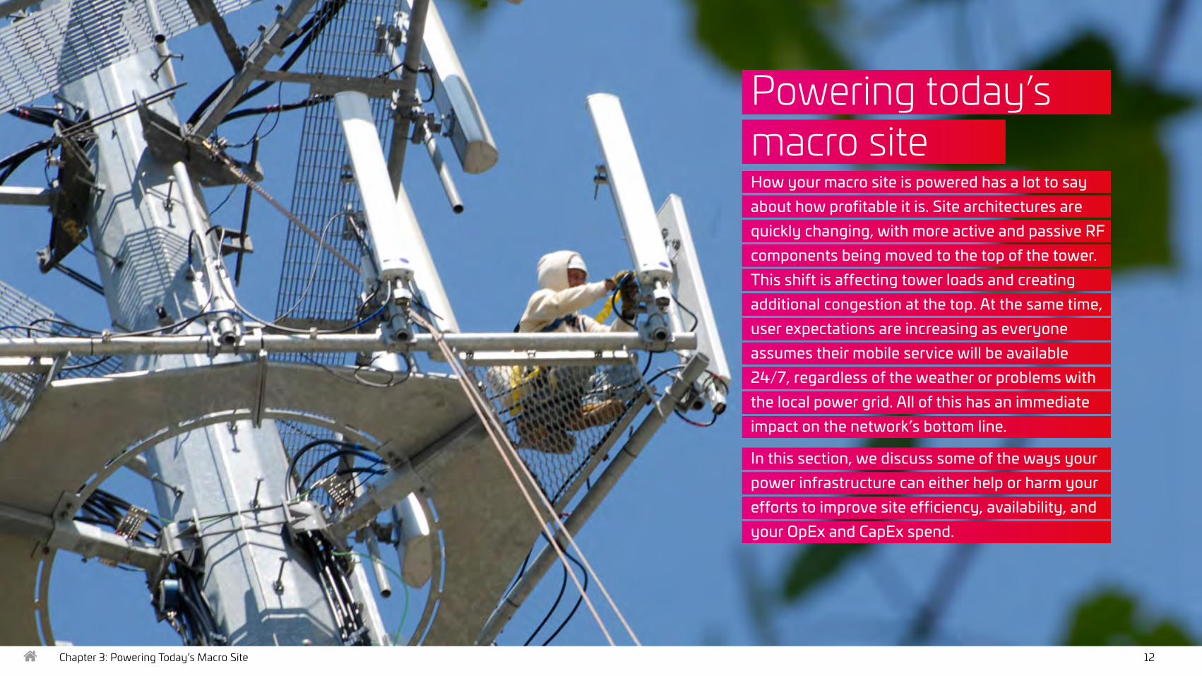
Powering today’s macro siteHow your macro site is powered has a lot to say about how profitable it is. Site architectures are quickly changing, with more active and passive RF components being moved to the top of the tower. This shift is affecting tower loads and creating additional congestion at the top. At the same time, user expectations are increasing as everyone assumes their mobile service will be available 24/7, regardless of the weather or problems with the local power grid. All of this has an immediate impact on the network’s bottom line.
In this section, we discuss some of the ways your power infrastructure can either help or harm your efforts to improve site efficiency, availability, and your OpEx and CapEx spend.

Chapter 3: Powering Today’s Macro Site 13
Power needs move to the topOne of the most significant architectural changes in cell site
design has been an explosion in the number of passive and
active RF components at the top of the tower. The main
drivers behind the change are the increasing number of
remote radio heads being deployed and the ramp-up
of 5G services.
Remote radio heads (RRHs) have become
one of the most important subsystems
of today’s distributed base stations.
In an RRH deployment, the baseband
equipment remains on the ground while
the remote radio head, containing the
base station’s RF circuitry, analog/digital
and up/down converters, is positioned
on the tower. This frees up more space
in the base station shelter and reduces
cooling costs. At the top of the tower,
the RRHs make MIMO operation easier
and increase base station efficiency.
In addition to the optical fiber
connecting it to the base station, the RRH
also requires a power feed. Herein lies
the challenge.
Each RRH needs a battery backup to
ensure operation in case of a power
failure. Locating the battery on the
tower isn’t feasible because of weather
risks, so it must be housed in the shelter,
far away from the RRH. Therefore, a
heavier gauge of power transmission
line is needed to sustain the voltage
required to operate the RRH. This adds
a significant weight onto the already-
overloaded tower.
Alternatively, you can convert the power
feed, based on its voltage drop, to a
higher voltage at ground level to ensure
the correct voltage at the RRH.This would
enable operators to deliver the right
amount of power to the RRHs without
having to substantially increase the
conductor gauge and risk exceeding the
tower’s loading capacities. This alternative
has, in fact, been developed and is being
used successfully. For more, see the next
section in this ebook on PowerShift.
–48 Vdc
dc power plant remote
ac in
dc out
dc load
dc in
dc out
Typical power feed for a remote radio head
Chapter 3: Powering Today’s Macro Site 14
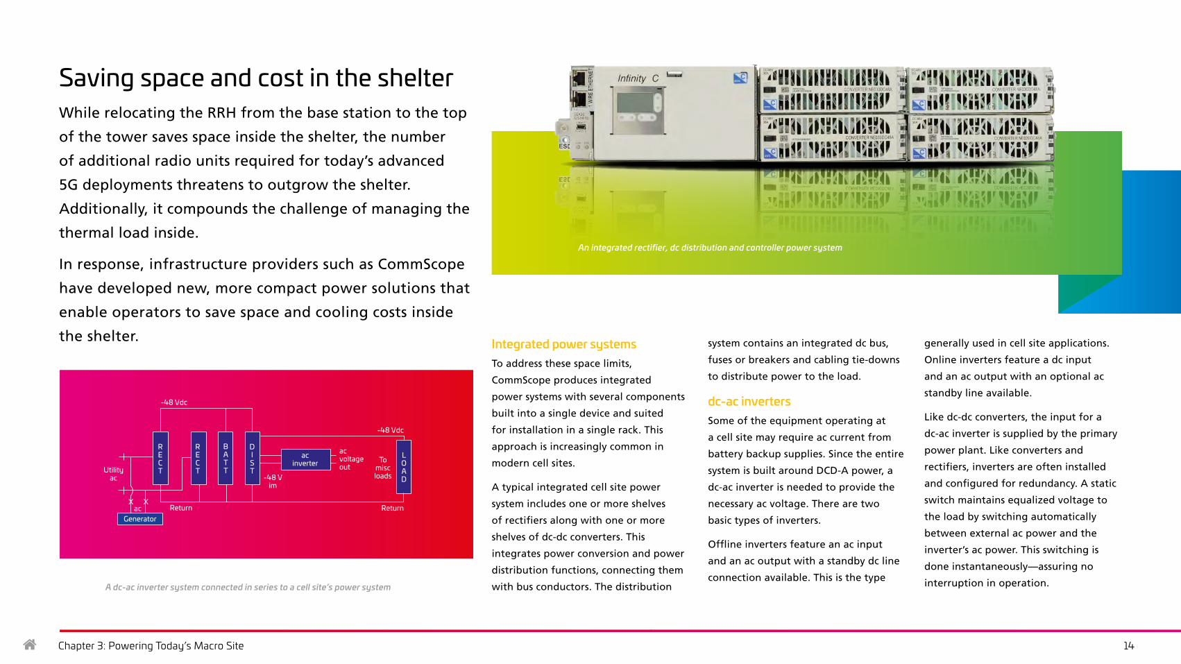
Saving space and cost in the shelterWhile relocating the RRH from the base station to the top
of the tower saves space inside the shelter, the number
of additional radio units required for today’s advanced
5G deployments threatens to outgrow the shelter.
Additionally, it compounds the challenge of managing the
thermal load inside.
In response, infrastructure providers such as CommScope
have developed new, more compact power solutions that
enable operators to save space and cooling costs inside
the shelter. Integrated power systemsTo address these space limits,
CommScope produces integrated
power systems with several components
built into a single device and suited
for installation in a single rack. This
approach is increasingly common in
modern cell sites.
A typical integrated cell site power
system includes one or more shelves
of rectifiers along with one or more
shelves of dc-dc converters. This
integrates power conversion and power
distribution functions, connecting them
with bus conductors. The distribution
system contains an integrated dc bus,
fuses or breakers and cabling tie-downs
to distribute power to the load.
dc-ac invertersSome of the equipment operating at
a cell site may require ac current from
battery backup supplies. Since the entire
system is built around DCD-A power, a
dc-ac inverter is needed to provide the
necessary ac voltage. There are two
basic types of inverters.
Offline inverters feature an ac input
and an ac output with a standby dc line
connection available. This is the type
generally used in cell site applications.
Online inverters feature a dc input
and an ac output with an optional ac
standby line available.
Like dc-dc converters, the input for a
dc-ac inverter is supplied by the primary
power plant. Like converters and
rectifiers, inverters are often installed
and configured for redundancy. A static
switch maintains equalized voltage to
the load by switching automatically
between external ac power and the
inverter’s ac power. This switching is
done instantaneously—assuring no
interruption in operation.
An integrated rectifier, dc distribution and controller power system
acinverter
GeneratorReturn
D I S T
B A T T
R E C T
R E C TUtility
ac -48 Vim
ac
-48 Vdc
LO A D
-48 Vdc
To misc loads
acvoltage out
Return
A dc-ac inverter system connected in series to a cell site’s power system
Chapter 3: Powering Today’s Macro Site 15
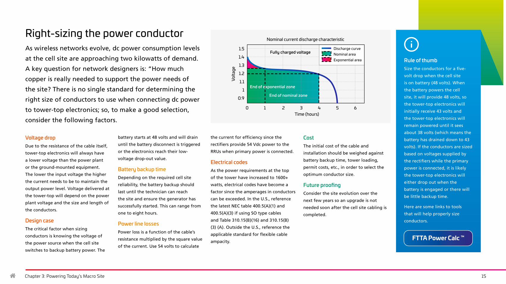
Right-sizing the power conductorAs wireless networks evolve, dc power consumption levels
at the cell site are approaching two kilowatts of demand.
A key question for network designers is: “How much
copper is really needed to support the power needs of
the site? There is no single standard for determining the
right size of conductors to use when connecting dc power
to tower-top electronics; so, to make a good selection,
consider the following factors.
Voltage dropDue to the resistance of the cable itself,
tower-top electronics will always have
a lower voltage than the power plant
or the ground-mounted equipment.
The lower the input voltage the higher
the current needs to be to maintain the
output power level. Voltage delivered at
the tower-top will depend on the power
plant voltage and the size and length of
the conductors.
Design caseThe critical factor when sizing
conductors is knowing the voltage of
the power source when the cell site
switches to backup battery power. The
battery starts at 48 volts and will drain
until the battery disconnect is triggered
or the electronics reach their low-
voltage drop-out value.
Battery backup timeDepending on the required cell site
reliability, the battery backup should
last until the technician can reach
the site and ensure the generator has
successfully started. This can range from
one to eight hours.
Power line lossesPower loss is a function of the cable’s
resistance multiplied by the square value
of the current. Use 54 volts to calculate
the current for efficiency since the
rectifiers provide 54 Vdc power to the
RRUs when primary power is connected.
Electrical codesAs the power requirements at the top
of the tower have increased to 1600+
watts, electrical codes have become a
factor since the amperages in conductors
can be exceeded. In the U.S., reference
the latest NEC table 400.5(A)(1) and
400.5(A)(3) if using SO type cables
and Table 310.15(B)(16) and 310.15(B)
(3) (A). Outside the U.S., reference the
applicable standard for flexible cable
ampacity.
CostThe initial cost of the cable and
installation should be weighed against
battery backup time, tower loading,
permit costs, etc., in order to select the
optimum conductor size.
Future proofingConsider the site evolution over the
next few years so an upgrade is not
needed soon after the cell site cabling is
completed.
Rule of thumbSize the conductors for a five-
volt drop when the cell site
is on battery (48 volts). When
the battery powers the cell
site, it will provide 48 volts, so
the tower-top electronics will
initially receive 43 volts and
the tower-top electronics will
remain powered until it sees
about 38 volts (which means the
battery has drained down to 43
volts). If the conductors are sized
based on voltages supplied by
the rectifiers while the primary
power is connected, it is likely
the tower-top electronics will
either drop out when the
battery is engaged or there will
be little backup time.
Here are some links to tools
that will help properly size
conductors.
Nominal current discharge characteristic
Volta
ge
Time (hours)
1.5
1.4
1.3
1.2
1.1
1
0.9
Discharge curveNominal areaExponential area
Fully charged voltage
0 1 2 3 4 5 6
End of exponential zone
End of nominal zone
FTTA Power Calc ™

Chapter 4: PowerShift Macro 16
PowerShift® MacroToday’s high-performance remote radio units (RRUs) consume more power, and operators are installing more of them to keep up with exploding data traffic. Radio equipment is also increasingly moving to the top of the tower, requiring more energy to deliver the right power level to the units.
To handle the increased power requirements, higher-wattage RRUs require additional power cables or larger power conductors, which use more copper. The increase in copper adds more weight on the tower—as do the thicker, more expensive cables required to support these new RRUs. Add higher installation costs and rising copper prices, and operators are feeling the financial squeeze of upgrading their network.

Chapter 4: PowerShift Macro 17
Take back the power with PowerShift®
With PowerShift, CommScope shatters the old paradigm
for delivering dc power to the tower, opening new
opportunities for efficiency and performance. With
PowerShift, operators can:
Baseband
Backhaul
To RRU
Batterybackup
120/220 Vac mains120/220 Vac mains
With PowerShift
Deliver the most e�cient voltage the
RRU can receiveProgrammable -50
to -75 VDC to power RRU
Baseband
Backhaul
To RRU
Batterybackup
Powerac to -48 volt
dc rectifier
Powerac to -48 volt
dc rectifier
Traditional-48 volt dc to all
required equipment including RRUs
Baseband
Backhaul
To RRU
Batterybackup
120/220 Vac mains120/220 Vac mains
With PowerShift
Deliver the most e�cient voltage the
RRU can receiveProgrammable -50
to -75 VDC to power RRU
Baseband
Backhaul
To RRU
Batterybackup
Powerac to -48 volt
dc rectifier
Powerac to -48 volt
dc rectifier
Traditional-48 volt dc to all
required equipment including RRUs
How it worksPowerShift gives you back the balance
of power by delivering the most
efficient voltage to your RRUs in real
time automatically—regardless of power
supply, distance, conductor size or RRU
power requirements. That optimization
enables you to decrease the cost of
network rollouts and upgrades and start
earning a greater return on investment
from day one. PowerShift also offers
the system design flexibility you need to
create an agile, future-ready network.
PowerShift works by optimizing backup
battery power by solving the voltage-
drop challenge discussed in the previous
section. PowerShift is inserted between
the battery plant and the trunk cable at
the base of the tower. The battery output
is fed into PowerShift, which adjusts its
output voltage (VPS) to compensate for
the cable voltage drop (VC), providing a
regulated, programmable voltage to the
RRU input (VL).
As the battery discharges down to 42
volts, PowerShift continues to boost its
output to maintain the programmed
input voltage to the RRU. This effectively
eliminates the RRU dropout voltage as a
major concern, ensuring full utilization
of backup battery runtime by the RRU.
PowerShift also eliminates having
to oversize the power plant and
battery backup to handle a worst case
scenario. So, MNOs can save cost and
accommodate higher-power RRUs in
the future.
Traditional setup Setup with PowerShift
Watch this brief video to learn more about the CommScope PowerShift Macro solutions
All while evolving their macro layer network to support
and deliver 5G-enabled services and beyond.
Reduce CapEx
Extend RF battery uptime by up to 50 percent
Achieve 97.7% power efficiency
Build future-ready infrastructure to accept higher-powered radios
Improve cost effectiveness of RRU upgrades

Chapter 4: PowerShift Macro 18
PowerShift® Macro portfolioEngineered to provide the most efficient and reliable power feed for your remote radio units, the PowerShift Macro
family can support multiple RRUs per circuit and maximize existing power infrastructue and power cable design
PowerShift V1 High Density & Capacity
Where cell capacity is critical, you can now
power up to 12 RRUs in 1-RU of rack space
with 1,460 watts and -54 Vdc per RRU.
• 4 modules, 3 RRUs per module
• Manual or Automatic setup for any power
level or conductor length
• Pulsar® controller (optional) to
manage performance
• All active electronics are centralized
• Extended battery backup life for
service continuity
• Dynamic voltage regulation at the RRU
PowerShift V2 Total Redundancy
Get the highest level of reliability with two
independent, redundant circuits per RRU
with bypass redundancy in a 3-RU chassis.
• 12 hot-swappable modules for
full redundancy
• 12 dedicated 2,000 watts circuits (1 per RRU)
• Manual or Automatic setup for any power
level or conductor length
• Pulsar® controller to manage performance
• Easy wiring, open accessible design
• Extended battery back up life for
service continuity
• Dynamic voltage regulation at the RRU
PowerShift V3 Modular High Power
Four 2,000-watt, -54 Vdc circuits in a 1-RU
chassis deliver the power and agility to
support future network growth.
• Modular from 1-RU to 3-RU (4-12 RRUs)
• 4 dedicated 2000W output circuits
(per 1-RU)
• Ganged front input and output
connections for easy installation in
tight spaces
• Pulsar® controller to manage
performance
• Extended battery back up life for
service continuity
• Dynamic voltage regulation at the RRU
PowerShift Constant Boost
Designed to meet budget constraints for
applications involving a low number of
high-power RRUs, where deployment
speed is key.
• 3 high-power circuits in 1-RU chassis
• 2,166 watts per circuit, 6,500 watts
per shelf
• Ability to gang the output circuits
• Front access for quick connectivity to
input and output connections
• Plug & play requires no configuration
or training
Chapter 4: PowerShift Macro 19
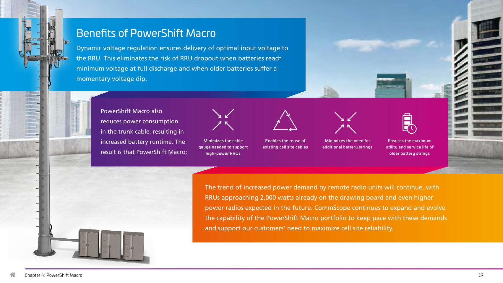
Benefits of PowerShift MacroDynamic voltage regulation ensures delivery of optimal input voltage to
the RRU. This eliminates the risk of RRU dropout when batteries reach
minimum voltage at full discharge and when older batteries suffer a
momentary voltage dip.
Minimizes the cable gauge needed to support
high-power RRUs
Enables the reuse of existing cell site cables
The trend of increased power demand by remote radio units will continue, with
RRUs approaching 2,000 watts already on the drawing board and even higher
power radios expected in the future. CommScope continues to expand and evolve
the capability of the PowerShift Macro portfolio to keep pace with these demands
and support our customers’ need to maximize cell site reliability.
Minimizes the need for additional battery strings
Ensures the maximum utility and service life of
older battery strings
PowerShift Macro also
reduces power consumption
in the trunk cable, resulting in
increased battery runtime. The
result is that PowerShift Macro:

Chapter 5: Powering Small Cell Metro Networks 20
Powering small cell metro networksDemand for wireless data is exploding, with 5G deployments increasing daily. Increased data traffic requires more computational power. As a result, networks must increase cell density, adding thousands of small cells, up to 10 for every LTE macro site. And they all need power. How do you run reliable power to every small cell—quickly and affordably? Your solutions are as limited as your time and budget. What’s your strategy?

Chapter 5: Powering Small Cell Metro Networks 21
Operational powerThe long lead time for deploying a
macro site enables the operator to assess
the power requirements and schedule a
power drop from the public utility long
in advance. The hectic pace of small cell
installation doesn’t allow for this. Often,
it’s not until after the site survey that
engineers discover there is no electrical
power close to some of the proposed
small cell locations. Tapping power
from existing buildings and/or getting
municipal approval involves negotiations
with building owners, tenants and local
agencies, and takes time.
Backup powerBattery backups can be added to
a macro site without affecting
permitting issues, which is not the case
with small cells. In some instances, the
power backup solution can take up
more space than the small cell itself;
if that backup solution involves a
diesel generator, there are additional
permitting and environmental issues to
overcome as well.
Space constraintsA macro tower site is pre-designed with
the power cabinet and power meter
typically housed in a dedicated space
within the shelter. In deploying urban
small cells, mobile network operators
must work within the constraints of the
available space. On lamp posts or utility
poles, for example, there may not be
room for a dedicated power source,
meter or backup power supply. Small cell
solutions that can integrate with street
furniture or are available pre-assembled
for faster turn-up can help operators
deal with these challenges.
Powering small cells is a whole new challengeThe advanced capabilities of today’s 5G small cells
create added power requirements. A typical three-sector
small cell can require 200–1,000 watts of power. With
thousands of small cells, the challenge is how to run
power to each one in a way that’s fast, efficient and
repeatable. The first step is realizing the vast differences
between powering macro cells versus small cells.
Macro cell deployment is a deliberate and structured
process of permitting, building and provisioning; each
tower location represents a unique, carefully planned
project. With small cells, operators don’t have that
luxury. They must accelerate rollouts using processes
that are agile enough to adapt to siting, backhaul and
power configurations on the fly. The following are some
of the key differences between powering macro and
small cell networks.
Chapter 5: Powering Small Cell Metro Networks 22
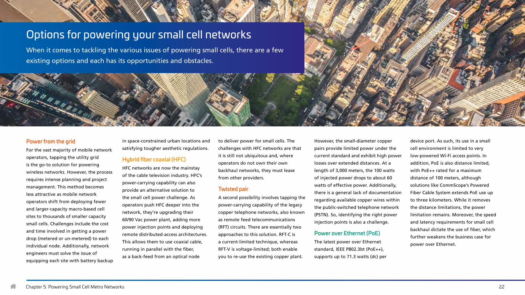
Options for powering your small cell networksWhen it comes to tackling the various issues of powering small cells, there are a few
existing options and each has its opportunities and obstacles.
Power from the gridFor the vast majority of mobile network
operators, tapping the utility grid
is the go-to solution for powering
wireless networks. However, the process
requires intense planning and project
management. This method becomes
less attractive as mobile network
operators shift from deploying fewer
and larger-capacity macro-based cell
sites to thousands of smaller capacity
small cells. Challenges include the cost
and time involved in getting a power
drop (metered or un-metered) to each
individual node. Additionally, network
engineers must solve the issue of
equipping each site with battery backup
in space-constrained urban locations and
satisfying tougher aesthetic regulations.
Hybrid fiber coaxial (HFC) HFC networks are now the mainstay
of the cable television industry. HFC’s
power-carrying capability can also
provide an alternative solution to
the small cell power challenge. As
operators push HFC deeper into the
network, they’re upgrading their
60/90 Vac power plant, adding more
power injection points and deploying
remote distributed-access architectures.
This allows them to use coaxial cable,
running in parallel with the fiber,
as a back-feed from an optical node
to deliver power for small cells. The
challenges with HFC networks are that
it is still not ubiquitous and, where
operators do not own their own
backhaul networks, they must lease
from other providers.
Twisted pair A second possibility involves tapping the
power-carrying capability of the legacy
copper telephone networks, also known
as remote feed telecommunications
(RFT) circuits. There are essentially two
approaches to this solution. RFT-C is
a current-limited technique, whereas
RFT-V is voltage-limited; both enable
you to re-use the existing copper plant.
However, the small-diameter copper
pairs provide limited power under the
current standard and exhibit high power
losses over extended distances. At a
length of 3,000 meters, the 100 watts
of injected power drops to about 60
watts of effective power. Additionally,
there is a general lack of documentation
regarding available copper wires within
the public-switched telephone network
(PSTN). So, identifying the right power
injection points is also a challenge.
Power over Ethernet (PoE) The latest power over Ethernet
standard, IEEE P802.3bt (PoE++),
supports up to 71.3 watts (dc) per
device port. As such, its use in a small
cell environment is limited to very
low-powered Wi-Fi access points. In
addition, PoE is also distance limited,
with PoE++ rated for a maximum
distance of 100 meters, although
solutions like CommScope’s Powered
Fiber Cable System extends PoE use up
to three kilometers. While it removes
the distance limitations, the power
limitation remains. Moreover, the speed
and latency requirements for small cell
backhaul dictate the use of fiber, which
further weakens the business case for
power over Ethernet.
Chapter 5: Powering Small Cell Metro Networks 23
CommScope has developed a solution that checks all the boxes. To learn more about PowerShift Metro for small cell networks, go to the next section. >>>
The importance of getting it right from Day 1Due to the accelerated pace of small cell deployment and more
extensive power infrastructure required, there will be a high price
to pay by not getting it right from the beginning. Meeting the large
demand in a compressed timeframe will be hard enough without
having to switch strategies six months down the road.
This is where having a go-to solution that has already been field-
tested and vetted can be a major help. As noted earlier, a fast, flexible
and repeatable process that enables operators to deploy quickly and
efficiently—regardless of backhaul needs, power requirements or
proximity to the grid—is essential to a successful small cell rollout.
Chapter 6: PowerShift Metro 24
PowerShift® MetroUntil recently, powering small cells required separate ac power drops for each site. Operators often have to reconfigure their network to stay on schedule and within budget. Then there’s the question of backup power. When the grid goes down, most small cells don’t have the backup power infrastructure that macro sites do. And power’s only half the problem. You still need to run fiber.
Chapter 6: PowerShift Metro 25
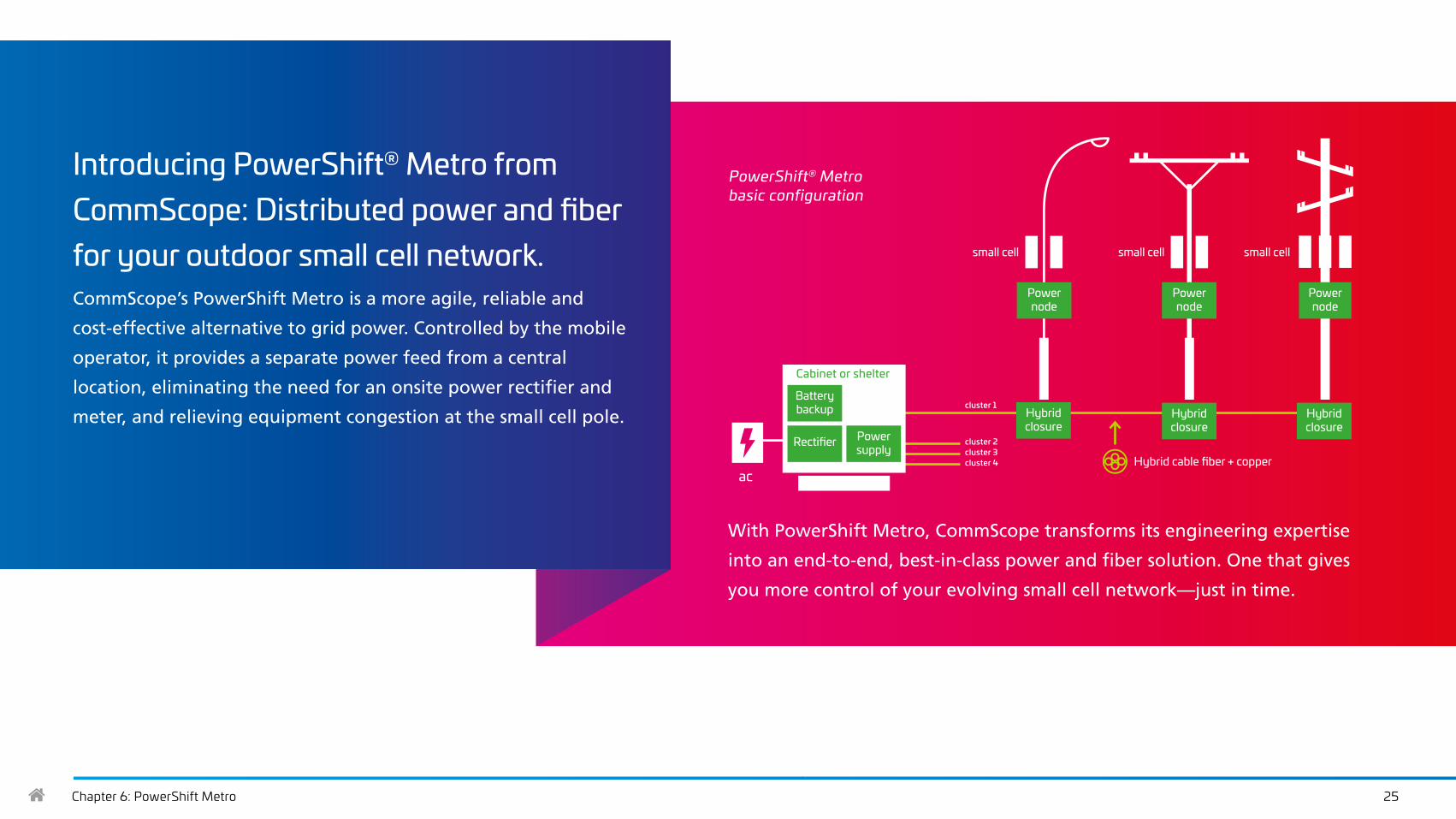
Introducing PowerShift® Metro from CommScope: Distributed power and fiber for your outdoor small cell network. CommScope’s PowerShift Metro is a more agile, reliable and
cost-effective alternative to grid power. Controlled by the mobile
operator, it provides a separate power feed from a central
location, eliminating the need for an onsite power rectifier and
meter, and relieving equipment congestion at the small cell pole.
With PowerShift Metro, CommScope transforms its engineering expertise
into an end-to-end, best-in-class power and fiber solution. One that gives
you more control of your evolving small cell network—just in time.
small cell
ac
Power node
Power node
Power node
Hybrid closure
Hybrid closure
Hybrid closure
Cabinet or shelter
Battery backup
Rectifier Power supply
PowerShift® Metro basic configuration
Hybrid cable fiber + copper
small cell small cell
cluster 1
cluster 2cluster 3cluster 4
Chapter 6: PowerShift Metro 26
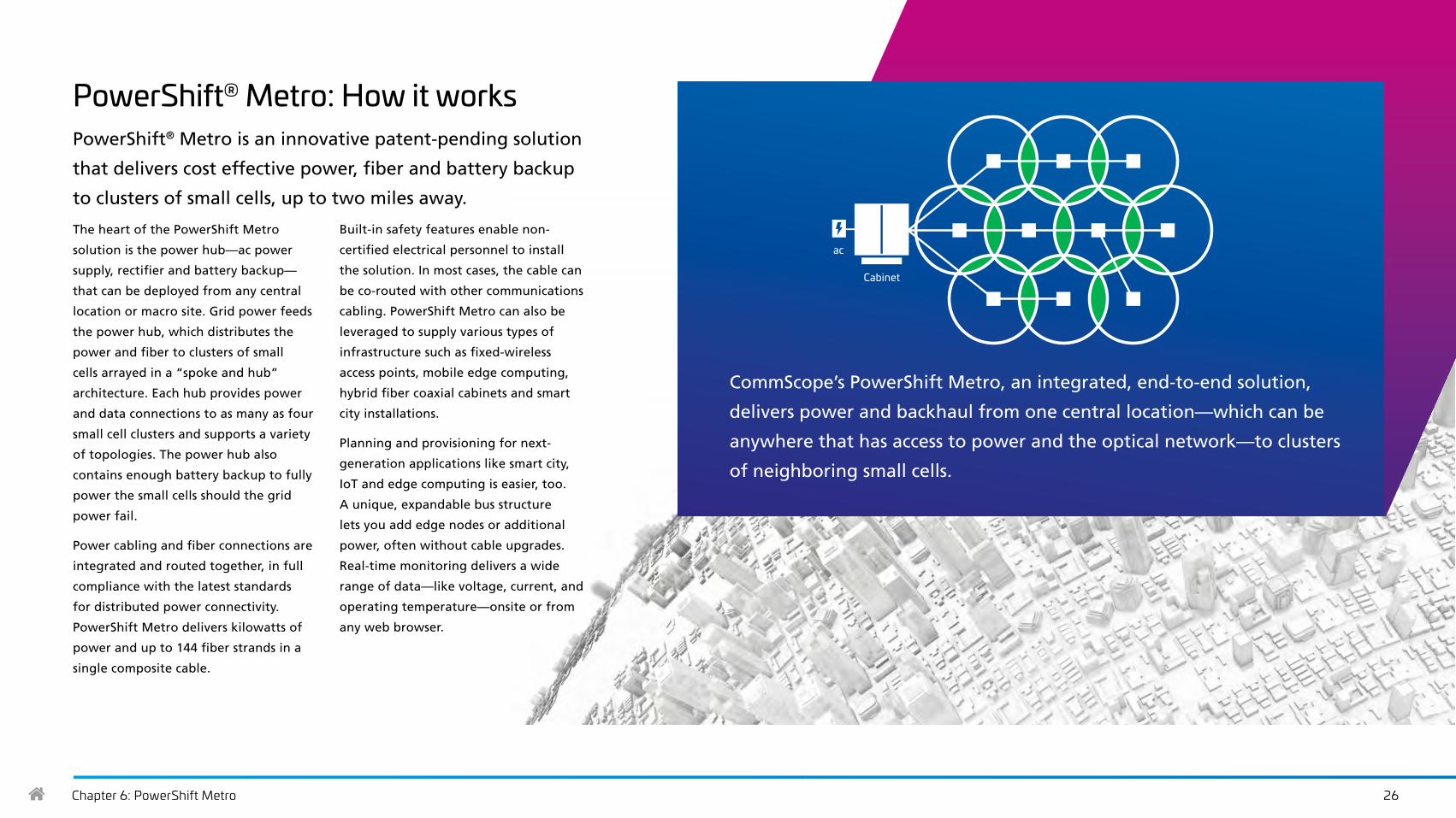
PowerShift® Metro: How it worksPowerShift® Metro is an innovative patent-pending solution
that delivers cost effective power, fiber and battery backup
to clusters of small cells, up to two miles away.
The heart of the PowerShift Metro
solution is the power hub—ac power
supply, rectifier and battery backup—
that can be deployed from any central
location or macro site. Grid power feeds
the power hub, which distributes the
power and fiber to clusters of small
cells arrayed in a “spoke and hub”
architecture. Each hub provides power
and data connections to as many as four
small cell clusters and supports a variety
of topologies. The power hub also
contains enough battery backup to fully
power the small cells should the grid
power fail.
Power cabling and fiber connections are
integrated and routed together, in full
compliance with the latest standards
for distributed power connectivity.
PowerShift Metro delivers kilowatts of
power and up to 144 fiber strands in a
single composite cable.
Built-in safety features enable non-
certified electrical personnel to install
the solution. In most cases, the cable can
be co-routed with other communications
cabling. PowerShift Metro can also be
leveraged to supply various types of
infrastructure such as fixed-wireless
access points, mobile edge computing,
hybrid fiber coaxial cabinets and smart
city installations.
Planning and provisioning for next-
generation applications like smart city,
IoT and edge computing is easier, too.
A unique, expandable bus structure
lets you add edge nodes or additional
power, often without cable upgrades.
Real-time monitoring delivers a wide
range of data—like voltage, current, and
operating temperature—onsite or from
any web browser.
ac
Cabinet
CommScope’s PowerShift Metro, an integrated, end-to-end solution,
delivers power and backhaul from one central location—which can be
anywhere that has access to power and the optical network—to clusters
of neighboring small cells.

Chapter 6: PowerShift Metro 27
PowerShift® Metro: The benefitsBy eliminating the excessive time and costs required for a
utility drop, mobile network operators can deploy power to
their small cells faster and less expensively in places where
power is not quickly and easily available. It also allows for
battery backups or generators at the centralized location to
support busy or mission-critical small cells.
By reducing the number of uncontrolled variables—
scheduling delays, electrician availability, additional
meters—the distributed power connectivity solution gives
operators full control over how, when and where to add
small cell coverage. This enables mobile network operators
to swiftly respond to new market opportunities and
increase speed to revenue—capabilities that are critical in
an increasingly competitive marketplace.
The variable-voltage power supply also reduces OpEx by
enabling peak shaving across small cell sites. When the
demand and cost for grid power are highest, MNOs can
avoid spikes in power consumption by leveling out peak use
of electricity. This not only reduces the amount of energy
purchased, but it also improves power grid stability.
Reduce operating costs and dramatically lower installation costs
Accelerate time to market
Ensure service continuity
Prepare your power infrastructure for the future
Reduce congestion at the pole
Key benefits:
Learn moreTo learn more about the CommScope PowerShift Metro solution, watch this brief video and see how PowerShift Metro can help you take control of your small cell networks.

Chapter 7: Conclusion 28
ConclusionAt home, work and play, the world relies on wireless networks like never before. But the demands on your network are quickly increasing. A relentless appetite for more bandwidth, fast-changing technologies, slowing subscriber growth and the arrival of 5G are causing massive disruptive shifts in the wireless landscape.
In response to these changes, outdoor networks are growing in scope and complexity. But what about the power distribution systems that enable them? As public power grids age, the always-on wireless services customers rely on become less reliable.
Your outdoor network is evolving. Your power distribution solutions must evolve as well.
Hopefully, this ebook has provided valuable information and inspiration to help you improve the operational resiliency of your power distribution system. But we’ve only skimmed the surface. For a deeper dive into how to develop a more reliable and efficient outdoor wireless power strategy, contact us.

www.commscope.comVisit our website or contact your local CommScope representative for more information.
© 2021 CommScope, Inc. All rights reserved. All trademarks identified by ® or ™ are registered trademarks or trademarks, respectively, of CommScope, Inc. This document is for planning purposes only and is not intended to modify or supplement any specifications or warranties relating to CommScope products or services.CO-116104-EN (09-21)
Always prepared, always pushing ourselves to do it better and smarter, keeping you ready for whatever is next.
That’s the value of CommScope.