eb-ew-i-s-11 installation and service manual · installation and service manual eb-ew-i-s-11 hot...
TRANSCRIPT
1
INSTALLATION AND SERVICE MANUALEB-EW-I-S-11
HOT WATER HEATING BOILERSDomestic Water Heaters
150,000 - 300,000 Btu/hr MODELS
WARRANTY
This is a gas appliance and should be installed by a licensed electrician and/or certified gas supplier. Service must be performed by a qualified service installer, service agency or the gas supplier.
IMPORTANT:
Installation and service must be performed by a qualified service installer, service agency or the gas supplier.
Factory warranty (shipped with appliance) does not apply to appliances improperly installed or improperly operated.
Experience has shown that improper installation or system design, rather than faulty equipment, is the cause of most operating problems.
1. Excessive water hardness causing a lime build-up in the copper tube is not the fault of the equipment and is not covered under the manufacturer’s warranty (see Water Treatment and Water Chemistry).
2. Excessive pitting and erosion on the inside of the copper tube may be caused by too much water velocity through the tubes and is not covered by the manufacturer’s warranty (see Boiler Flow Rates and Temperature Rise for flow requirements).
This manual supplies information for the installation, operation and servicing of the appliance. It is strongly recommended that this manual be reviewed completely before proceeding with an installation.
Improper installation, adjustment, alteration, service or maintenance can cause property damage, personal injury or loss of life. Refer to this manual for assistance or additional information, consult a qualified installer, service agency or the gas supplier. This appliance contains material that has been identified as carcinogenic, or possibly carcinogenic to humans.
SPECIAL INSTRUCTIONSTO OWNER
Note: Retain this manual for future information.
� WARNING
CHECKING EQUIPMENT
Upon receiving equipment, check for signs of shipping damage. Pay particular attention to parts accompanying the appliance which may show signs of being hit or otherwise being mishandled. Verify total number of pieces shown on packing slip with those actually received. In case there is damage or a shortage, immediately notify carrier.
DO NOT use this appliance if any part has been under water. The possible damage to a flooded appliance can be extensive and present numerous safety hazards. Any appliance that has been under water ust be replaced.
If the information in this manual is not followed exactly, a fire or explosion may result causing property damage, personal injury or loss of life.
This appliance MUST NOT be installed in any location where gasoline or flammable vapors are likely to be present.
WHAT TO DO IF YOU SMELL GAS
• Do not try to light any appliance.• Do not touch any electric switch; do not use any
phone in your building.• Immediately call your gas supplier from a neighbors
phone. Follow the gas supplier’s instructions.• If you cannot reach your gas supplier, call the fire
department.• Installation and service must be performed by a
qualified installer, service agency or the gas supplier.
� WARNING
LOW LEAD CONTENT

2
Consult and follow local Building and Fire Regulations and other Safety Codes that apply to this installation. Consult your local gas utility company to authorize and inspect all gas and flue connections.
Should overheating occur or the gas supply fail to shut off, do not turn off or disconnect the electrical supply to the pump. Instead, shut off the gas supply at a location external to the appliance.
To minimize the possibility of serious personal injury, fire or damage to your appliance, never violate the following safety rules.
1. Boilers and water heaters are heat producing appliances. To avoid damage or injury, do not store materials against the appliance or the vent-air intake system. Use proper care to avoid unnecessary contact (especially children) with the appliance and vent-air intake components.
2. Never cover your appliance, lean anything against it, store trash or debris near it, stand on it or in any way block the flow of fresh air to your ap pli ance.
3. UNDER NO CIRCUMSTANCES must flammable materials such as gasoline or paint thinner be used or stored in the vicinity of this appliance, vent-air intake system or any location from which fumes could reach the appliance or vent-air intake system.
� WARNING
� WARNING
IMPORTANT
Your conventionally vented gas appliance must have a supply of fresh air circulating around it during burner operation for proper gas combustion and proper venting.
IMPORTANT
Warranty ............................................................................1Safety Warnings .................................................................1Codes ..................................................................................3Location ..............................................................................3Clearances ...........................................................................4Combustion/Ventilation Air Requirements.....................4Venting - General ..............................................................6Conventional Venting .......................................................8E+Venting ........................................................................11Direct Vent Sidewall ........................................................14Direct Vent Vertical .........................................................18Outdoor Installation .......................................................22Gas Supply ........................................................................23Gas Pressure & Piping .....................................................24Manifold Pressure Adjustment .......................................26Supply Pressure Measurement ........................................28Water Connections ..........................................................29Relief Valve .......................................................................29Flow Switch ......................................................................29Gas Valve ..........................................................................29Electrical Requirements ...................................................30Temperature Adjustment ................................................30Outdoor Air Reset Option ..............................................32Lighting Instructions .......................................................34Hot Surface Ignition Control ..........................................35Operation & Diagnostic Lights .......................................35Ignition & Control Timings ............................................35Freeze Protection .............................................................36Maintenance .....................................................................36Flame Patterns..................................................................37Combustion Air Adjustments .........................................37Burner Cleaning ...............................................................38Heat Exchanger Inspection .............................................39Lubrication .......................................................................39Gas Train ..........................................................................40Heating Boiler ..................................................................40Typical Piping ..................................................................40Pump Requirements ........................................................40Pressure Drop Curve .......................................................41Boiler Pump Operation ...................................................41Bypass Requirements .......................................................41Low Temperature Systems ..............................................42Boiler Flow Rates .............................................................43Temperature Rise Chart ..................................................43Placing Boiler in Operation.............................................44Boiler Temperature Control ...........................................45Remote Thermostat Connection ....................................45Domestic Water Heater ..................................................46Water Velocity Control ...................................................46Water Chemistry ..............................................................46Piping Requirements .......................................................47Pump Operation ..............................................................47Thermostat Adjustment ..................................................48Relief Valve .......................................................................49Wiring Diagrams..............................................................50Troubleshooting Charts ..................................................54Revision Notes ..................................................Back Cover
CONTENTSThe information contained in this manual isin tend ed for use by qualified professional in stall ers, service technicians or gas suppliers. Con sult your local expert for proper installation or service procedures.
CONTENTS

3
CODES
The equipment shall be installed in accordance with those installation regulations in force in the local area where the installation is to be made. These regulations shall be carefully followed in all cases. Authorities having jurisdiction shall be consulted before installations are made. In the absence of such requirements, the installation shall conform to the latest edition of the National Fuel Gas Code, ANSI Z223.1 and/or CAN/CGA-B149 Installation Code. Where required by the authority having jurisdiction, the installation must conform to American Society of Mechanical Engineers Safety Code for Controls and Safety Devices for Automatically Fired Boilers, ASME CSD-1. All boilers conform to the latest edition of the ASME Boiler and Pressure Vessel Code, Section IV. Where required by the authority having jurisdiction in Canada, the installation must comply with the CSA International CAN/CGA-B149 .1 and/or B149.2 Installation Code and/or local codes.
This appliance meets the safe lighting performance criteria with the gas manifold and control assembly provided, as specified in the ANSI standards for gas-fired appliances, ANSI Z21.13 and ANSI Z21.10.3
INSTALLATION PROCEDURE
FIG. 1 Typical (Front View) Cabinet Construction
FIG. 2 Typical Boiler (Rear View) Cabinet Construction
LOCATION OF UNIT1. Locate the appliance so that if water connections should
leak, water damage will not occur. When such locations cannot be avoided, it is recommended that a suitable drain pan, adequately drained, be installed under the appliance. The pan must not restrict combustion air flow. Under no circumstances is the manufacturer to be held responsible for water damage in connection with this appliance, or any of its components.
2. The appliance must be installed so that the ignition system components are protected from water (dripping, spraying, rain, etc.) during appliance operation and service (circulator replacement, control replacement, etc.).
3. Appliances located in a residential garage and in adjacent spaces that open to the garage and are not part of the living space of a dwelling appliance must be installed so that all burners and burner ignition devices have a minimum clearance of not less than 18” (46 cm) above the floor. The appliance must be located or protected so that it is not subject to physical damage by a moving vehicle.
4. DO NOT install this appliance in any location where gasoline or flammable vapors are likely to be present.
5. The appliance must be installed on a level floor. A combustible wood floor may be used without additional bases or special floor buildup. Maintain required clearances from combustible surfaces.

4
CLEARANCES FROM COMBUSTIBLE CONSTRUCTION
6. The appliance must not be installed on carpet or other combustible material other than wood flooring.
7. Outdoor models require the installation of an optional outdoor kit. Instructions for mounting the parts in the kit are included in the venting section of this manual. Outdoor models MUST NOT be installed directly on the ground. The outdoor appliance must be installed on a concrete, brick, block or wood flooring. Outdoor models have additional special location and clearance requirements. These are specifically addressed in the venting section under Outdoor Installation. A windproof/rainproof cabinet protects the appliance from the weather.
FIG. 3 Installation Clearances Drawing
Clearances from Combustible Construction:
Right Side - 1" (25.4 mm)Rear - 1" (25.4 mm)Left Side - 6" (15 cm) (24" (61 cm) suggested for service)Front - 3" (76.2 mm) (24" (61 cm) suggested for service)Top - 3" (76.2 mm)Flue - 1" (25.4mm)
All appliances have been approved for closet installation .
Allow sufficient space for servicing pipe connections, pump and other auxiliary equipment, as well as the appliance.
COMBUSTION AND VENTILATION AIR REQUIREMENTS FOR
CONVENTIONALLY VENTED APPLIANCES
Provisions for combustion and ventilation air must be in accordance with Section 5.3, Air for Combustion and Ventilation, of the latest edition of the National Fuel Gas Code, ANSI Z223.1, in Canada, the latest edition of CGA Standard B149 Installation Code for Gas Burning Appliances and Equipment, or applicable provisions of the local building codes.
The room where the appliance is installed MUST be provided with properly sized openings to assure adequate combustion air and proper ventilation when the appliance is installed with conventional venting.
FIG. 4 Combustion Air Direct from Outside
1. If air is taken directly from outside the building with no duct, provide two permanent openings:
a. Combustion air opening, with a minimum free area of one square inch per 4000 Btu/hr input (5.5cm2 per kW). This opening must be located within 12" (30 cm) of the top of the enclosure.
b. Ventilation air opening, with a minimum free area of one square inch per 4000 Btu/hr input (5.5cm2 per kW). This opening must be located within 12" (30 cm) of the bottom of the enclosure.
5
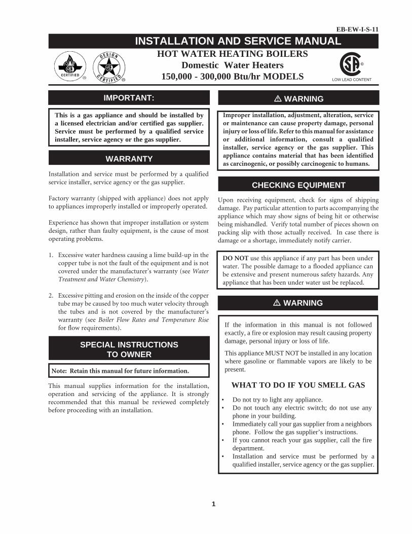
2. If combustion and ventilation air is taken from the outdoors using a duct to deliver the air to the mechanical room, each of the two openings should be sized based on a minimum free area of one square inch per 2000 Btu/hr (11cm2 per kW).
FIG. 5 Combustion Air through Ducts
FIG. 6 Air from an Interior Space
3. If air is taken from another interior space, each of the two openings specified above should have a net free area of one square inch for each 1000 Btu/hr (22cm2 per kW) of input, but not less than 100 square inches (645 cm2).
FIG. 7 Combustion Air from Outside - Single Opening
4. If a single combustion air opening is provided to bring combustion air in directly from the outdoors, the opening must be sized based on a minimum free area of one square inch per 3000 Btu/hr (7cm2 per kW). This opening must be located within 12” (30 cm) of the top of the enclosure.
5. See venting section for combustion air requirements on E+Venting and direct vent applications.
TABLE AMINIMUM RECOMMENDED COMBUSTION
AIR SUPPLY TO MECHANICAL ROOMBoiler Input
Outside Air*2 Openings
Outside Air*1 Opening
Inside Air*2 Openings
150,000 38 in2 50 in2 150 in2
199,000 50 in2 67 in2 200 in2
250,000 63 in2 83 in2 250 in2
300,000 75 in2 100 in2 300 in2
*Outside air openings shall directly communicate with the outdoors. When combustion air is drawn from the outside through a duct, the net free area of each opening must have twice (2 times) the free area required for each Outside Air Openings. The above requirements are for the appliance only, additional gas fired appliances in the mechanical room will require an increase in the net free area to supply adequate combustion air for all appliances. Combustion air requirements are based on the latest edition of the National Fuel Gas Code, ANSI Z223.1, in Canada refer to CSA International CAN/CGA B149.1 or B149.2 Installation Code. Check all local code requirements for combustion air.

6
All dimensions based on net free area in square inches. Metal louvers or screens reduce the free area of a combustion air opening a minimum of approximately 25%. Check with louver manufacturers for exact net free area of louvers. Where two openings are provided, one must be within 12"(30 cm) of the ceiling and one must be within 12" (30 cm) of the floor of the mechanical room. Each opening must have net free area as specified in Table A. Single openings shall commence within 12" (30 cm) of the ceiling.
Under no circumstances should the equipment room ever be under a negative pressure. Particular care should be taken where exhaust fans, attic fans, clothes dryers, compressors, air handling units, etc. may take away air from the unit.
� CAUTION
The combustion air supply must be completely free of any chemical fumes which may be corrosive to the appliance. Common chemical fumes which must be avoided are fluorocarbons and other halogenated compounds, most commonly present as refrigerants or solvents, such as Freon, trichlorethylene, perchlorethylene, chlorine, etc. These chemicals, when burned form acids which quickly attack the heat exchanger finned tubes, tube headers, flue collectors, and the vent system. The result is improper combustion and a non-warrantable, premature appliance failure.
EXHAUST FANS: Any fan or equipment which exhausts air from the mechanical room may deplete the combustion air supply and/or cause a down draft in the venting system. Spillage of flue products from the venting system into an occupied living space can cause a very hazardous condition that must be immediately corrected. If a fan is used to supply combustion air to the boiler room, the installer must make sure that it does not cause drafts which could lead to nuisance operational problems with the appliance.
E+Vent and Direct Vent venting systems have specific requirements for combustion air ducts from the outside which are directly connected to the appliance. See the requirements for this combustion air duct in the venting section for each specialized vent system.
VENTING
General
Vent installations for connection to gas vents or chimneys must be in accordance with Part 7, “Venting of Equipment,” of the latest edition of the National Fuel Gas Code, ANSI Z223.1, in Canada, the latest edition of CAN/CGA B149 Installation Code for Gas Burning Appliances and Equipment or applicable provisions of the local building codes.
Conventionally vented applications where outside air is used must have adequate combustion and ventilation air supplied to the mechanical room in accordance with the latest edition of the National Fuel Gas Code, ANSI Z223.1, in Canada, the latest edition of CAN/CGA B149 Installation Code for Gas Burning Appliances and Equipment, or applicable provisions of the local building codes.
The distance of the vent terminal from adjacent buildings, windows that open and building openings MUST comply with the latest edition of the National Fuel Gas Code, ANSI Z223.1, in Canada, the latest edition of CAN/CGA B149 Installation Code for Gas Burning Appliances and Equipment.
Vent connection is made directly to the top of the appliance. No additional draft diverter is required. The connection from the appliance vent to the stack must be made as direct as possible.
The negative draft in conventional vent installations must be within the range of a negative 0.02 to 0.05 inches water to ensure proper operation. All draft readings are made while appliance is in stable operation (approximately 2 to 5 minutes).
Locate units as close as possible to chimney or gas vent.
See the vent material requirements for each of the specific venting options. Conventional venting systems use Type “B” double wall vent material. Direct vent systems have specific vent kits and material requirements noted for each application.
Any vent materials not provided or specified must be listed by a nationally recognized test agency for use as vent material.
Avoid long horizontal runs of the vent pipe, 90° elbows, reductions and restrictions. Horizontal portions of the venting system shall be supported to prevent sagging. Horizontal runs must slope upwards not less than 1/4 inch per foot (21 mm per meter) from the appliance to the vent terminal. Follow manufacturers instructions.
The weight of the venting system must not rest on the appliance. Adequate support of the venting system must be provided in compliance with local codes and other applicable codes. All connections should be secured with rustproof sheet metal screws.
Barometric Damper Location
Any venting system option that requires a barometric damper must adhere to the following directions for optimum performance.

7
The preferred location for the barometric damper is in a tee or collar installed in the vertical pipe rising from the appliance’s flue outlet. The barometric damper MUST NOT be installed in a bull head tee installed on the appliance’s flue outlet. The tee or collar containing the barometric damper should be approximately three feet vertically above the connection to appliance’s flue outlet. This location ensures that any positive velocity pressure from the appliance’s internal combustion fan is dissipated and the flue products are rising due to buoyancy generated from the temperature of the flue products. Adjust weights on damper to ensure that draft is maintained within the specified range.
FIG. 8 Vent Termination from a Peaked Roof 10' or less from Ridge
FIG. 9 Vent Termination from a Peaked Roof more than 10' from Ridge
The vertical vent terminal should exhaust outside the building at least 2 feet (61 cm) above the highest point of the roof within a 10 foot (3.05 m) radius of the termination.
The vertical termination must be a minimum of 3 feet (91 cm) above the point of exit.
FIG. 10 Vent Termination from a Flat Roof 10' or Less from Parapet Wall
FIG. 11 Vent Termination from a Flat Roof more than 10' from Parapet Wall
A vertical termination less than 10 feet (3.05 m) from a parapet wall must be a minimum of 2 feet (61 cm) higher than the parapet wall.
The vent cap should have a minimum clearance of 4 feet (1.22 m) horizontally from and in no case above or below,

8
unless a 4 foot (1.22 m) horizontal distance is maintained from electric meters, gas meters, regulators and relief equipment.
Do not terminate the vent in a window well, stairwell, alcove, courtyard or other recessed area. The vent cannot terminate below grade.
Do not use an existing chimney as a raceway if another appliance or fireplace is vented through the chimney.
To avoid a blocked flue condition, keep the vent cap clear of snow, ice, leaves, debris, etc.
Flue gases will form a white plume in winter. Plume could obstruct window view.
Flue gas condensate can freeze on exterior surfaces or on the vent cap. Frozen condensate on the vent cap can result in a blocked flue condition. Flue gas condensate can cause discoloration of exterior building surfaces. Adjacent brick or masonry surfaces should be protected with a rust resistant sheet metal plate.
Examine the venting system at least once a year. Check all joints and vent pipe connections for tightness. Also check for corrosion or deterioration. Immediately correct any problems observed in the venting system.
IMPORTANT
VENT SYSTEM OPTIONS
This appliance has five venting options. They are:
1. Conventional Negative Draft Venting Conventional negative draft venting with vertical termination.
2. E+ with a Vertical Conventional Vent E+Vent with a vertical conventional vent for flue products and a combustion air pipe from either the sidewall or roof top.
3. Direct Venting with Sidewall Terminations Direct vent with sidewall terminations for flue products and combustion air.
4. Direct Venting with Vertical Terminations Direct vent with vertical through-roof terminations for flue products and combustion air.
5. Outdoor Installation Outdoor installation consists of the installation of
a special vent cap / top assembly, gas valve cover, deflectors, and a weatherproof junction box.
All appliances are shipped from the factory equipped for conventional negative draft venting. All other optional vent systems require the installation of specific vent kits and venting materials. The following is a detailed explanation of the installation requirements for each venting system, components used and part numbers of vent kits for each model.
E+Conventional Venting
FIG. 12 Conventional Venting Installation
Follow all requirements in the General Venting section for venting flue products to the outdoors, obtaining adequate combustion and ventilation air and general installation instructions. All conventionally vented appliances must have combustion and ventilation air supplied to the mechanical room in accordance with the latest edition of the National Fuel Gas Code, ANSI Z223.1, in Canada, the latest edition of CAN/CGA B149 Installation Code for Gas Burning Appliances and Equipment, or applicable provisions of the local building codes.
A bell increaser is installed directly on the appliance vent outlet. The bell increases the vent size by 1 inch (25.4 mm) in diameter. The bell increaser MUST be installed on the appliance vent outlet for all conventional negative draft vent systems. Vent connection is made directly to the bell increaser on top of the appliance. No additional draft diverter or barometric damper is required on single appliance installations with a dedicated stack and a negative draft within the specified range of a negative 0.02 to 0.05 inches water. Multiple appliance installations with combined venting or common venting with other negative draft appliances require that each appliance must have a barometric damper installed to regulate draft within the proper range. If the draft in a dedicated stack for a single
A CONVENTIONAL NEGATIVE DRAFT VENTING SYSTEM

9
appliance installation exceeds the specified draft, a barometric damper must be installed to control draft.
The vent pipe sizes are:
TABLE BCONVENTIONAL VENT FLUE SIZE
Input Btu/hr Flue Size*
150,000 5"
199,999 5"
250,000 6"
300,000 6"
*Vent size with 1" bell increaser installed for conventional negative draft venting
On a conventionally vented, negative draft appliance, the connection from the vent to the stack or vent termination outside the building MUST be made with listed Type “B” double wall (or equivalent) vent connectors and must be direct as possible with no reduction in diameter. Use the National Fuel Gas Code venting tables for double wall vent to properly size all vent connectors and stacks. The Type “B” vent and accessories, such as firestop spacers, thimbles, caps, etc., MUST be installed in accordance with the manufacturer’s listing. The vent connector and firestop must provide correct spacing to combustible surfaces and seal to the vent connector on the upper and lower sides of each floor or ceiling through which the vent connector passes.
Locate appliances as close as possible to chimney or gas vent.
Horizontal runs must slope upwards not less than 1/4 inch per foot (21 mm per meter) from the appliance to the vent terminal. Follow manufacturers instructions.
Vent connectors serving appliances vented by natural draft shall not be connected to any portion of a mechanical draft system operating under positive pressure. Connection to a positive pressure stack may cause flue products to be discharged into the living space causing serious health injury.
Any vent materials not provided or specified must be listed by a nationally recognized test agency for use as vent material.
The vent terminal should be vertical and exhaust outside the building at least 2 feet (61 cm) above the highest point of the roof within a 10 foot (3.05 m) radius of the termination.
The vertical termination must be a minimum of 3 feet(91 cm) above the point of exit.
A vertical termination less than 10 feet (3.05 m) from a parapet wall must be a minimum of 2 feet (61 cm) higher than the parapet wall.
The vent cap should have a minimum clearance of 4 feet (1.22 m) horizontally from and in no case above or below, unless a 4 foot (1.22 m) horizontal distance is maintained from electric meters, gas meters, regulators and relief equipment.
MASONRY CHIMNEY INSTALLATIONS (CONVENTIONAL VENTING ONLY)
A masonry chimney must be properly sized for the installation of a high efficiency gas fired appliance. Venting of a high efficiency appliance into a cold or oversized masonry chimney can result in operational and safety problems. Exterior masonry chimneys, with one or more sides exposed to cold outdoor temperatures, are more likely to have venting problems. The temperature of the flue products from a high efficiency appliance may not be able to sufficiently heat the masonry structure of the chimney to generate proper draft. This will result in condensing of flue products, damage the masonry flue/tile, insufficient draft and possible spillage of flue products into an occupied living space. Carefully inspect all chimney systems before installation. If there is any doubt about the sizing or condition of a masonry chimney, it must be relined with a properly sized and approved chimney liner system.
Inspection of a Masonry Chimney
A masonry chimney must be carefully inspected to determine its suitability for the venting of flue products. A clay tile lined chimney must be structurally sound, straight and free of misaligned tile, gaps between liner sections, missing sections of liner or any signs of condensate drainage at the breaching or clean out. If there is any doubt about the condition of a masonry chimney, it must be relined. An unlined masonry chimney must not be used to vent flue products from this high efficiency appliance. An unlined chimney must be relined with an approved chimney liner system when a new appliance is being attached to it. Metallic liner systems (Type “B” double-wall or flexible or rigid metallic liners) are recommended. Consult with local code officials to determine code requirements or the advisability of using or relining a masonry chimney.
Common venting systems may be too large when an existing appliance is removed. At the time of removal of an existing appliance, the following steps shall be followed with each appliance remaining connected to the common venting system placed in operation, while other appliances remaining connected to the common venting system are not in operation.

10
1. Seal any unused opening in the common venting system.
2. Visually inspect the venting system for proper size and horizontal pitch and determine there is no blockage or restriction, leakage, corrosion and other unsafe condition.
3. Insofar as is practical, close all building doors and windows and all doors between the space in which the appliances remaining connected to the common venting system are located and other spaces of the building. Turn on clothes dryers and any other appliances not connected to the common venting system. Turn on any exhaust fans, such as range hoods and bathroom exhausts, so they will operate at maximum speed. Do not operate a summer exhaust fan. Close fire place dampers.
4. Place in operation, the appliance being inspected. Follow the lighting instructions. Adjust thermostat so appliance will operate continuously.
5. Test for spillage at the draft hood/relief opening after 5 minutes of main burner operation. Use the flame of a match or candle, or smoke from a cigarette, cigar or pipe.
6. After it has been determined that each appliance remaining connected to the common venting system properly vents when tested as above, return doors, windows, exhaust fans, fireplace dampers and other gas burning appliances to there previous conditions of use.
7. Any improper operation of the common venting system should be corrected so that the installation conforms to the latest edition of the National Fuel Gas Code, ANSI Z223.1, in Canada, the latest edition of CAN/CGA Standard B149 Installation Code for Gas Burning Appliances and Equipment. When resizing any portion of the common venting system, the common venting system should be resized to approach the minimum size as determined using the appropriate tables in Appendix G in the latest edition of the National Fuel Gas Code, ANSI Z223.1, in Canada, the latest edition of CAN/CGA Standard B149 Installation Code for Gas Burning Appliances and Equipment.
A CONVENTIONAL VERTICAL NEGATIVE DRAFT VENTING SYSTEM WITH COMBUSTION AIR PROVIDED FROM A SIDEWALL OR ROOF TOP
INLET CAP
Follow all requirements in the General Venting section and Conventional Negative Draft Venting for venting flue products to the outdoors and general installation instructions.
This vent system uses two pipes, one vertical pipe with a roof top termination for the flue products and one pipe for combustion air. The combustion air pipe may terminate horizontally with a sidewall air inlet or vertically with a roof top air inlet. A bell increaser is installed directly on the vent outlet. This bell increases the vent size by 1” (25.4 mm) in diameter. The bell increaser MUST be installed on the vent outlet for all conventional negative draft vent systems. Vent connection is made directly to the bell increaser on top of the appliance. No additional draft diverter or barometric damper is required on single appliance installations with a dedicated stack and a negative draft maintained between 0.02 to 0.05 inches water. The flue may be combined with the vent from any other negative draft, Category I appliances. Multiple appliance installations common vented with other negative draft appliances require that each appliance must have a barometric damper installed to regulate draft within the proper range. The common vent and connectors from multiple appliances must be sized per the requirements of the venting tables for type “B” double wall vents in the latest edition of the National Fuel Gas Code, ANSI Z223.1.
The sidewall or vertical roof top E+Vent combustion air supply system has specific vent material and installation requirements. The air inlet pipe connects directly to the appliance to supply combustion air. In most installations, the combustion air inlet pipe will be a dedicated system with one air inlet pipe per appliance. Multiple air inlets may be combined if the guidelines in “Combined Air Inlet Points” are followed. The air inlet pipe will be connected to a combustion air inlet cap as specified in this section.
Combustion air supplied from outdoors must be free of contaminants (see Combustion and Ventilation Air Section).

11
FIG. 13 E+Vent with Sidewall Air
Sidewall Air Inlet
The sidewall air inlet cap is supplied in the E+Sidewall Vent Kit which should be ordered from the manufacturer. This sidewall cap will supply combustion air for a single appliance only.
Locate appliances as close as possible to sidewall where the combustion air supply system will be installed.
To prevent recirculation of flue products from an adjacent vent cap into the combustion air inlet, follow all applicable clearance requirements in the latest edition of the National Fuel Gas Code and instructions in this manual.
The combustion air inlet cap must be installed at least one foot (30 cm) above ground level and above normal snow levels.
FIG. 14 E+Vent with Rooftop Air
Vertical Roof Top Air Inlet
The air inlet cap for the vertical roof top air inlet is assembled from components purchased locally. The air inlet cap consist of two 90° ells installed at the point of termination for the air inlet pipe. The first 90° ell is installed on the roof top at the highest vertical point of the air inlet pipe and turned horizontal, the second 90° ell is installed on the horizontal outlet of the first ell and turned down. A 90° ell and a 90° street ell may be used to make this assembly. If a straight piece of pipe is used between the two ells, it should not exceed 6” (51 mm) in length. The termination ell on the air inlet must be located a minimum of 12” (30 cm) above the roof or above normal levels of snow accumulation.
FIG. 15 Air Inlet Cap for RoofTop Termination
The point of termination for the combustion air inlet cap MUST be at least 2 feet (61 cm) below the point of flue gas termination (vent cap) if it is located within 10’ (3.05 m) of the flue outlet. Use care to ensure that the 90° ell assembly is properly installed on the air inlet pipe.
The combustion air inlet cap must not be installed closer than 10 feet (3.05 m) from an inside corner of an L-shaped structure.
The combustion air inlet cap must be installed at least one foot (30 cm) above the roof top and above normal snow levels.
Incorrect installation and/or location of the air inlet cap can allow the discharge of flue products to be drawn into the combustion process on the heater. This can result in incomplete combustion and potentially hazardous levels of carbon monoxide in the flue products. This will cause operational problems with the heater and possible spillage of flue products which can cause personal injury, death or property damage

12
Combined Air Inlet Points
The air inlet pipes from multiple appliances can be combined to a single common connection if the common air inlet pipe has a cross sectional area equal to or larger than the total area of all air inlet pipes connected to the common air inlet pipe. [Example: two 5" air inlet pipes (19.6 in2 area each) have a total area of 39.2 in2 require a 8"(50.3 in2 area) common air inlet pipe.] The air inlet point for multiple appliance air inlets must be provided with an exterior opening which has a free area equal to or greater than the total area of all air inlet pipes connected to the common air inlet. This exterior opening for combustion air must connect directly to the outdoors. The total length of the combined air inlet pipe must not exceed a maximum of 50 (15.25 m) equivalent feet. You must deduct the restriction in area provided by any screens, grills or louvers installed in the common air inlet point. These are common on the sidewall air inlet openings. Screens, grills or louvers installed in the common air inlet can reduce the free area of the opening from 25% to 75% based on the materials used.
Air Inlet Pipe Materials
The air inlet pipe(s) must be sealed. Choose acceptable combustion air inlet pipe materials from those specified in this section.
Select air inlet pipe material from the following specified materials:
PVC or CPVC (4", 5" or 6" I.D.)*
Dryer Vent (not recommended for roof top air inlet)
Galvanized steel vent pipe with joints and seams sealed as specified below.
Type “B” double wall vent with joints and seams sealed as specified below.
* Plastic pipe requires an adapter (not provided) to transition between the air inlet and cap.
Using other vent or air intake materials, failure to properly seal all seams and joints or failure to follow vent pipe manufacturer’s instructions can result in personal injury, death or property damage. Mixing of venting materials will void the warranty and certification of the appliance.
� WARNING
The use of double wall vent material for the combustion air inlet pipe is recommended in cold climates to prevent the condensation of airborne moisture in the incoming combustion air.
NOTE:
Length of Air Inlet Pipe
The total equivalent length of the sidewall or vertical roof top E+Vent combustion air inlet pipe must not exceed a maximum of 50 (15.24 m) equivalent feet in length. Subtract 5 feet (1.52 m) for each elbow in the air intake system. Do not exceed limits for the combustion air inlet piping lengths.
Sealing of Type “B” double wall vent material or galvanized vent pipe material used for air inlet pipe on a sidewall or vertical roof top E+Vent Combustion Air Supply System
1. Seal all joints and seams of the air inlet pipe using either Aluminum Foil Duct Tape meeting UL Standard 723 or 181A-P or a high quality UL Listed silicon sealant such as those manufactured by Dow Corning or General Electric.
2. Do not install seams of vent pipe on the bottom of horizontal runs.
3. Secure all joints with a minimum of three sheet metal screws or pop rivets. Apply aluminum foil duct tape or silicone sealant to all screws or rivets installed in the vent pipe.
4. Ensure that the air inlet pipes are properly supported.
The PVC or CPVC air inlet pipe should be cleaned and sealed with the pipe manufacturers recommended solvents and standard commercial pipe cement for the material used. The PVC, CPVC, or Dryer Vent air inlet pipe should use a silicone sealant to ensure a proper seal at the appliance connection and the air inlet cap connection. Dryer vent should use a screw type clamp to seal the vent to the appliance and air inlet cap. Proper sealing of the air inlet pipe ensures that combustion air will be free of contaminants and supplied in proper volume.
When a sidewall or vertical roof top E+Vent combustion air supply system is disconnected for any reason, the air inlet pipe must be resealed to ensure that combustion air will be free of contaminants and supplied in proper volume.

13
Failure to properly seal all joints and seams as required in the air inlet piping may result in flue gas recirculation, spillage of flue products and carbon monoxide emissions causing severe personal injury or death.
� WARNING
FIG. 16 Sidewall Air Inlet Cap
Vent Kits
The sidewall E+Vent Kit must be ordered from the manufacturer for single appliance installations with sidewall air inlet. The part number for each kit is listed by appliance size. Each kit includes a sidewall combustion air inlet cap to supply air to a single appliance and instructions for proper installation. The flue pipe, roof top vent cap and air inlet pipes are purchased locally. The air inlet cap for a vertical roof top termination is fabricated from materials purchased locally. The air inlet cap for the combined air supply from multiple appliances must be purchased locally.
TABLE CSIDEWALL VENT KITS
Input Btu/hr
Conventional Flue Size*
Air Inlet Pipe**
Sidewall E+Vent Kit
150,000 5" 4" SVK3020
199,999 5" 4" SVK3020
250,000 6" 5" SVK3021
300,000 6" 6" SVK3021
*Vent size with 1" increaser installed for conventional negative draft venting.
**Minimum diameter, installer may increase diameter one pipe size for ease of installation if needed. A 6" diameter air inlet cap may be ordered as Sidewall E+Vent Kit SVK3022.
The sidewall air inlet cap supplied in the Sidewall E+Vent Kit is used to supply combustion air to a single appliance. The roof top vent cap for flue products should be a standard commercial cap purchased locally. The use of a sidewall air inlet cap other than the manufacturers recommended cap for single appliance installations or use of a common air inlet cap for multiple appliances with insufficient free area and/or protection from wind and weather may result in operational problems with the appliance or potentially hazardous spillage of flue products which can cause personal injury, death or property damage.
Venting of Flue Products
On a conventionally vented, negative draft appliance, the connection from the vent to the stack or vent termination outside the building MUST be made with listed Type “B” double wall (or equivalent) vent connectors and must be direct as possible with no reduction in diameter. The bell increaser, factory installed on the flue outlet, MUST be used. Use the National Fuel Gas Code venting tables for double wall vent to properly size all vent connectors and stacks. The type “B” vent and accessories, such as firestop spacers, thimbles, caps, etc., MUST be installed in accordance with the manufacturers listing. The vent connector and firestop must provide correct spacing to combustible surfaces and seal to the vent connector on the upper and lower sides of each floor or ceiling through which the vent connector passes. The vertical flue of an E+Vent must maintain a negative draft within the specified range.
An appliance installed in an application such as a restaurant or industrial installation where exhaust fans, air handlers or other mechanical equipment are creating an excessive negative pressure in the mechanical room may require that the appliance be installed with an optional direct vent system. Local codes which require the installation of a certified direct vent system must use one of the ANSI tested direct vent systems. The direct vent system uses a sealedAL29-4C stainless steel vent material and a sealed combustion air inlet pipe. See E+Vertical Direct Vent System or E+Sidewall Direct Vent System installation requirements in this manual.
The connection from the vent to the vent termination outside the building MUST be made with type “B” double wall vent materials and must be direct as possible with no reduction in diameter. The vent accessories, such as firestop spacers, thimbles, caps, etc., MUST be from the same vent material and installed in accordance with the manufacturers listing. The vent connection through the roof must provide correct spacing to combustible surfaces.

14
Horizontal runs must slope upwards not less than 1/4 inch per foot (21 mm per meter) from the appliance to the vent terminal. Follow manufacturers instructions. The vent cap shall terminate at least 3 feet (91 cm) above any forced air inlet within 10 feet (3.05 m).
The vent shall terminate at least 4 feet (1.22 m) below, 4 feet (1.22 m) horizontally from or 1 foot (30 cm) above any door, window or gravity air inlet to the building.
Do not terminate the vent in a window well, stairwell, alcove, courtyard other recessed area. The vent can not terminate below grade.
Flue gas condensate can freeze on exterior walls or on the vent cap. Frozen condensate on the vent cap can result in a blocked flue condition. Some discoloration to exterior building surfaces can be expected. Adjacent brick or masonry surfaces should be protected with a rust resistant sheet metal plate.
The vent cap should have a minimum clearance of 4 feet (1.22 m) horizontally from and in no case above or below, unless a 4 foot (1.22 m) horizontal distance is maintained from electric meters, gas meters, regulators and relief equipment.
Locate units as close as possible to chimney or gas vent.
Vent connectors serving appliances vented by natural draft shall not be connected to any portion of a mechanical draft system operating under positive pressure. Connection to a positive pressure stack may cause flue products to be discharged into the living space causing serious health injury.
The Vent terminal should be vertical and exhaust outside the building at least 2 feet (61 cm) above the highest point of the roof within a 10 foot (3.05 m) radius of the termination.
The vertical termination must be a minimum of 3 feet(91 cm) above the point of exit in the rooftop.
A vertical termination less than 10 feet (3.05 m) from a parapet wall must be a minimum of 2 feet (61 cm) higher than the parapet wall.
The vent cap should have a minimum clearance of 4 feet (1.22 m) horizontally from and in no case above or below, unless a 4 foot (1.22 m) horizontal distance is maintained from electric meters, gas meters, regulators and relief equipment.
An appliance which is shut down or will not operate may experience freezing due to convective air flow in the air inlet pipe connected to the unit. Proper freeze protection must be provided, see see Freeze Protection.
� CAUTION
FIG. 17 E+Vent Sidewall Direct Vent System
A DIRECT VENT SYSTEM WITH SIDEWALL TERMINATIONS
Follow all requirements in the General Venting section for venting flue products to the outdoors and general installation instructions. All direct vent appliances must have combustion air supplied directly to the appliance with a separate air pipe.
The bell increaser, installed on the appliance vent outlet, must be removed. The bell increaser is NOT USED with the direct vent system. Vent connection is made directly to the top of the appliance. No additional bell increaser, draft diverter or barometric damper is required. The direct vent system uses a two pipe system, one pipe for the flue products and one pipe for the combustion air supply. The sidewall vented flue MUST be a dedicated stack. The flue can NOT be combined with any other appliance vent or common vent from multiple appliances. The vent on a direct vent system may have a positive pressure in the flue which requires all vent joints and seams to be sealed gas-tight. The sidewall direct vent system has specific vent material and installation requirements. The flue from a direct vent system must have a condensate drain with provisions to properly collect and dispose of any condensate that may occur in the venting system. Choose acceptable vent materials from those listed on page 15.
The E+Sidewall Direct Vent System

15
Sidewall Air Inlet for Direct Vent
The combustion air inlet pipe must also be a dedicated system with one air inlet pipe per appliance. The air inlet pipes from multiple appliances can NOT be combined to a single common connection. The air inlet pipe connects directly to the appliance to supply combustion air. The air inlet pipe must be sealed. Choose acceptable combustion air pipe materials from those specified in this section.
FIG. 18 Sidewall Direct Vent Caps
Sidewall Direct Vent Kits
The sidewall direct vent kit must be ordered from the appliance manufacturer. The part number for each kit is listed by appliance size. Each kit includes a sidewall vent cap for flue products, a firestop, a combustion air inlet cap and instructions for proper installation. The flue pipe and air inlet pipes are purchased locally.
TABLE DSIDEWALL DIRECT VENT KITS
Input Btu/hr
Direct Vent Flue Size*
Air Inlet Pipe**
Sidewall E+Vent Kit
150,000 4" 4" HDK3013
199,999 4" 4" HDK3013
250,000 5" 5" HDK3014
300,000 5" 5 HDK3014
*Minimum diameter, installer may increase diameter one pipe size for ease of installation if needed.
The sidewall vent cap and sidewall air inlet cap supplied in the Sidewall Direct Vent Kit MUST be used to vent the flue products to the outdoors and supply combustion air. Use of a vent cap and/or air inlet cap other than the manufacturers recommended caps may result in operational problems with the appliance or potentially hazardous spillage of flue products which can cause personal injury, death or property damage.
Flue Pipe Materials
Select venting material from the following specified vent materials:
Heat-Fab Saf-T CI Vent with AL29-4C stainless steel (Call 800-772-0739 for nearest distributor)
Z-Flex Z-Vent with AL29-4C stainless steel(Call 1-800-654-5600 for nearest distributor)
Protech Systems Inc. Fas-N-Seal Vent withAL29-4C stainless steel (Call 1-800-766-3473 for nearest distributor)
Flex-L International, Inc. Star-34 Vent withAL29-4C stainless steel(Call 1-800-561-1980 for nearest distributor)
Metal-Fab Corr/Guard Vent with AL29-4C stainless steel (Call 1-800-835-2830 for nearest distributor) or other listed AL29-4C vent systems suitable for positive pressure
Air Inlet Pipe Materials
Select air inlet pipe material from the following specified materials:
PVC or CPVC (4”, 5”or 6” I.D.)*
Dryer Vent
Galvanized steel vent pipe with joints and seams sealed as specified below.
Type “B” double wall vent with joints and seams sealed as specified below.
* Plastic pipe requires an adapter (not provided) to transition between the air inlet and cap.

16
The use of double wall vent material for the combustion air inlet pipe is recommended in cold climates to prevent the condensation of airborne moisture in the incoming combustion air.
NOTE:
Using other vent or air intake materials, failure to properly seal all seams and joints or failure to follow vent pipe manufacturer’s instructions can result in personal injury, death or property damage. Mixing of vent materials will void the warranty and certification of the appliance.
� WARNING
Length of Flue Pipe and Air Inlet Pipe
The total equivalent length of the direct vent flue pipe or the air inlet pipe must not exceed a maximum of 50 (15.24 m) equivalent feet in length for each pipe. Subtract 5 feet(1.52 m) for each elbow in the vent pipe or air intake system. Do not exceed limits for piping lengths.
Sealing of Type “B” double wall vent material or galvanized vent pipe material used for air inlet pipe on a Direct Vent System
1. Seal all joints and seams of the air inlet pipe using either Aluminum Foil Duct Tape meeting UL Standard 723 or 181A-P or a high quality UL Listed silicon sealant such as those manufactured by Dow Corning or General Electric.
2. Do not install seams of vent pipe on the bottom of horizontal runs.
3. Secure all joints with a minimum of three sheet metal screws or pop rivets. Apply aluminum foil duct tape or silicone sealant to all screws or rivets installed in the vent pipe.
4. Ensure that the air inlet pipes are properly supported.
The PVC or CPVC air inlet pipe should be cleaned and sealed with the pipe manufacturers recommended solvents and standard commercial pipe cement for the material used. The PVC, CPVC, or Dryer Vent air inlet pipe should use a silicone sealant to ensure a proper seal at the appliance connection and the air inlet cap connection. Dryer vent should use a screw type clamp to seal the vent to the appliance and air inlet cap. Proper sealing of the air inlet pipe ensures that combustion air will be free of contaminants and supplied in proper volume.
Sealing of vent material for use with the Sidewall Direct Vent system
The vent materials, Heat-Fab Saf-T CI Vent, Z-Flex Z-Vent, Protech Systems Fas-N-Seal Vent, Flex-L Star-34 Vent, Metal-Fab Corr/Guard Vent or listed AL29-4C vent system suitable for positive pressure, must be installed and sealed per the vent manufacturers installation instructions.
FIG. 19 Drain Tee Installation
Drain Tee Installation
A drain tee must be installed in the vent pipe to collect and dispose of any condensate that may occur in the vent system. The drain tee must be installed as the first fitting after the horizontal ell on the top of the appliance. See the typical vent installation drawings. Plastic drain tubing, sized per the vent manufacturers instructions, shall be provided as a drain line from the tee. The drain tubing must have a trap provided by a 3” (76 mm) diameter circular trap loop in the drain tubing. Prime the trap loop by pouring a small quantity of water into the drain hose before assembly to the vent. Secure the trap loop in position with nylon wire ties. Use caution not to collapse or restrict the condensate drain line with the nylon wire ties. The condensate drain must be routed to a suitable drain for disposal of condensate that may occur in the direct vent system. Refer to the condensate drain installation instructions as supplied by the manufacturer of the vent material. See “Freeze Protection” for more information.
When a direct vent system is disconnected for any reason, the flue must be reassembled and resealed according to the vent manufacturers instructions. The air inlet pipe must also be resealed to ensure that combustion air will be free of contaminants and supplied in proper volume.

17
Failure to properly seal all vent joints and seams may result in flue gas spillage and carbon monoxide causing severe personal injury or death.
� DANGER
The connection from the vent to the vent termination outside the building MUST be made with one of the specified vent materials and must be direct as possible with no reduction in diameter. The vent accessories not otherwise provided, such as firestop spacers, thimbles, caps, etc., MUST be from the same vent material manufacturer and installed in accordance with the manufacturers listing. The vent connection through the sidewall must provide correct spacing to combustible surfaces. The vent pipe connection to the sidewall vent cap MUST have a gas-tight seal to prevent the leakage of flue products.
FIG. 20 Sidewall Vent Locations
Venting of Flue Products
Locate appliances as close as possible to the sidewall where the vent for flue products will be installed.
Horizontal runs must slope upwards not less than 1/4 inch per foot (21 mm per meter) from the appliance to the vent terminal. Follow manufacturers instructions.
The vent cap shall terminate at least 3 feet (91 cm) above any forced air inlet within 10 feet (3.05 m).
The vent shall terminate at least 4 feet (1.22 m) below, 4 feet (1.22 m) horizontally from or 1 foot (30 cm) above any door, window or gravity air inlet to the building.
The vent system shall terminate at least 1 foot (30 cm) above grade and above normal snow levels.
The vent for a direct vent system shall NOT terminate above public walkways.
The vent shall not be installed closer than 10 feet (3.05 m) from an inside corner of an L-shaped structure.
Do not terminate the vent in a window well, stairwell, alcove, courtyard, or other recessed area. The vent can not terminate below grade.
Flue gas condensate can freeze on exterior walls or on the vent cap. Frozen condensate on the vent cap can result in a blocked flue condition. Some discoloration to exterior building surfaces can be expected. Adjacent brick or masonry surfaces should be protected with a rust resistant sheet metal plate.
The vent cap should have a minimum clearance of 4 feet (1.22 m) horizontally from and in no case above or below, unless a 4 foot (1.22 m) horizontal distance is maintained from electric meters, gas meters, regulators and relief equipment.
Combustion Air Inlet
Combustion air supply pipes can NOT be combined into a single pipe for multiple appliance installations.
Combustion air supplied from outdoors must be free of contaminants (See Combustion and Ventilation Air). To prevent recirculation of flue products into the combustion air inlet, follow all instructions in this section.
To help prevent recirculation of flue products: The combustion air inlet cap MUST NOT be installed above the flue outlet cap.
The combustion air inlet cap must be installed horizontally or below the flue outlet and MUST maintain a minimum 3 foot (91 cm) radius clearance from the flue outlet cap.
The combustion air inlet cap and vent cap for flue outlet MUST be located on the same sidewall and in the same pressure zone.
The combustion air inlet cap must not be installed closer than 10 feet (3.05 m) from an inside corner of a L-shaped structure.
The combustion air inlet cap must be installed at least 1 foot (30 cm) above ground level and above normal snow levels

18
Multiple Sidewall Direct Vent Installations
FIG. 21 Installation of Multiple Direct Vent Caps
The combustion air inlet caps for multiple appliance installations must maintain the minimum 3 foot (91 cm) radius clearance below or horizontally from the closest flue outlet. Multiple flue outlet caps may be installed side by side and multiple air inlet caps may be installed side by side but the 3 foot (91 cm) radius minimum clearance between air inlet and flue outlet must be maintained. All clearance and installation requirements in this section and the applicable portions of the general venting section must be maintained on multiple appliance installations.
Appliances which are shut down or will not operate may experience freezing due to convective air flow in the air inlet pipe connected to the unit. Proper freeze protection must be provided, see Freeze Protection.
� CAUTION
FIG. 22 Verical Direct Vent Installation
The E+Vertical Direct Vent System
A DIRECT VENT SYSTEM WITH VERTOCAL THROUGH-ROOF
TERMINATIONS
Follow all requirements in the General Venting section for venting flue products to the outdoors and general installation instructions. All direct vent appliances must have combustion air supplied directly to the appliance with a separate air pipe.
The bell increaser, installed on the vent outlet, must be removed. The bell increaser is NOT USED with the direct vent system. Vent connection is made directly to the top of the appliance. No additional bell increaser, draft diverter or barometric damper is required. The direct vent system uses a two pipe system, one pipe for the flue products and one pipe for the combustion air supply. The vertical through-roof vented flue MUST be a dedicated stack. The flue can NOT be combined with any other appliance vent or common vent from multiple appliances. The vent on a direct vent system may have a positive pressure in the flue which requires all vent joints and seams to be sealed gas-tight. The direct vent vertical through-roof venting system has specific vent material and installation requirements. The flue from a direct vent system must have a condensate drain with provisions to properly collect and dispose of any condensate that may occur in the venting system. Choose acceptable vent materials from those listed below.
The combustion air inlet pipe must also be a dedicated system with one air inlet pipe per appliance. The air inlet pipes from multiple appliances can NOT be combined to a single common connection. The air inlet pipe connects directly to the appliance to supply combustion air.

19
The air inlet pipe must be sealed. Choose acceptable combustion air pipe materials from those specified in this section.
The direct vent vertical through-roof vent system DOES NOT require the purchase of a special vent kit from the manufacturer. The specified flue pipe, vertical through-roof flue outlet cap, air inlet pipe and components to assemble the through-roof combustion air inlet cap are purchased locally.
TABLE EDIRECT VENT FLUE AND AIR PIPE SIZES
Input Btu/hr
Direct Vent Flue Size*
Air Inlet Pipe**
Sidewall E+Vent Kit
150,000 4" 4" HDK3013
199,999 4" 4" HDK3013
250,000 5" 5" HDK3014
300,000 5" 5 HDK3014
*Minimum diameter, installer may increase diameter one pipe size for ease of installation if needed.
FIG. 23 Air Inlet Cap for Vertical Direct Vent System
Roof Top Air Inlet Cap for Vertical Direct Vent
The air inlet cap for the vertical through-roof direct vent system is assembled from components purchased locally. The air inlet cap consist of two 90° ells installed at the point of termination for the air inlet pipe. The first 90° ell is installed on the roof top at the highest vertical point of the air inlet pipe and turned horizontal, the second 90° ell is installed on the horizontal outlet of the first ell and turned down. A 90° ell and a 90° street ell may be used
to make this assembly. If a straight piece of pipe is used between the two ells, it should not exceed 6” (51 mm) in length. The termination ell on the air inlet must be located a minimum of 12” (30 cm) above the roof or above normal levels of snow accumulation. The point of termination for the air inlet must be 24” (61 cm) lower than the point of flue gas termination if it is located within 10’ (3.05 m) of the flue outlet. Use care to ensure that the 90° ell assembly is properly installed on the air inlet pipe. Incorrect installation and/or location of the air inlet cap can allow the discharge of flue products to be drawn into the combustion process on the heater. This can result in incomplete combustion and potentially hazardous levels of carbon monoxide in the flue products. This will cause operational problems with the heater and possible spillage of flue products which can cause personal injury, death or property damage
A vertical vent cap as specified by the vent material manufacturer MUST be used to vent the flue products to the outdoors. The vent cap for the flue products is purchased locally. The point of discharge for the flue products in a vertical direct vent system must terminate a minimum of 24” (61 cm) above the point where the air inlet is located if the air inlet is within a 10’ (3.05 m) radius of the flue discharge. Incorrect installation and/or location of the vent cap for flue products can allow the discharge of flue products to be drawn into the combustion process on the heater. This can result in incomplete combustion and potentially hazardous levels of carbon monoxide in the flue products. This will cause operational problems with the heater and possible spillage of flue products which can cause personal injury, death or property damage
Flue Pipe Materials
Select venting material from the following specified vent materials:
Heat-Fab Saf-T CI Vent with AL29-4C stainless steel(Call 1-800-772-0739 for nearest distributor)
Z-Flex Z-Vent with AL29-4C stainless steel(Call 1-800-654-5600 for nearest distributor)
Protech Systems Inc. Fas-N-Seal Vent with AL29-4C stainless steel(Call 1-800-766-3473 for nearest distributor)
Flex-L International, Inc. Star-34 Vent withAL29-4C stainless steel(Call 1-800-561-1980 for nearest distributor)
Metal-Fab Corr/Guard Vent with AL29-4C stainless steel (Call 1-800-835-2830 for nearest distributor) or other listed AL29-4C vent systems suitable for positive pressure

20
Air Inlet Pipe Materials
Select air inlet pipe material from the following specified materials:
PVC or CPVC (4", 5" or 6" I.D.)*
Dryer Vent
Galvanized steel vent pipe with joints and seams sealed as specified below.
Type “B” double wall vent with joints and seams sealed as specified below.
* Plastic pipe requires an adapter (not provided) to transition between the air inlet and cap.
Using other vent or air intake materials, failure to properly seal all seams and joints or failure to follow vent pipe manufacturer’s instructions can result in personal injury, death or property damage. Mixing of vent materials will void the warranty and certification of the appliance.
� WARNING
Length of Flue Pipe and Air Inlet Pipe
The total equivalent length of the direct vent flue pipe or the air inlet pipe must not exceed a maximum of 50 (15.24 m) equivalent feet in length for each pipe. Subtract 5 feet (1.52 m) for each elbow in the vent pipe or air intake system. Do not exceed limits for piping lengths.
Sealing of Type “B” double wall vent material or galvanized vent pipe material used for air inlet pipe on a Direct Vent System
1. Seal all joints and seams of the air inlet pipe using either Aluminum Foil Duct Tape meeting UL Standard 723 or 181A-P or a high quality UL Listed silicon sealant such as those manufactured by Dow Corning or General Electric.
2. Do not install seams of vent pipe on the bottom of horizontal runs.
3. Secure all joints with a minimum of three sheet metal screws or pop rivets. Apply aluminum foil duct tape or silicone sealant to all screws or rivets installed in the vent pipe.
4. Ensure that the vent pipe and air inlet pipes are properly supported.
The PVC or CPVC air inlet pipe should be cleaned and sealed with the pipe manufacturers recommended solvents and standard commercial pipe cement for the material used. The PVC, CPVC, or Dryer Vent air inlet pipe should use a silicone sealant to ensure a proper seal at the boiler connection. Dryer vent should use a screw type clamp to seal the vent to the boiler and the assembly of 90° ells which make up the air inlet cap. Proper sealing of the air inlet pipe ensures that combustion air will be free of contaminants and supplied in proper volume.
Sealing of vent material for use with the Vertical Direct Vent System
The vent materials, Heat-Fab Saf-T CI Vent, Z-Flex Z-Vent, Protech Systems Fas-N-Seal Vent, Flex-L Star-34,Metal-Fab Corr/Guard Vent or listed AL29-4C vent system suitable for positive pressure, must be installed and sealed per the vent manufacturers installation instructions.
FIG. 24 Drain Tee Installation
Drain Tee Installation A drain tee must be installed in the vent pipe to collect and dispose of any condensate that may occur in the vent system. The drain tee must be installed as the first fitting after the horizontal ell on the top of the appliance. See the typical vent installation drawings. Plastic drain tubing, sized per the vent manufacturers instructions, shall be provided as a drain line from the tee. The drain tubing must have a trap provided by a 3" (76 mm) diameter circular trap loop in the drain tubing. Prime the trap loop by pouring a small quantity of water into the drain hose before assembly to the vent. Secure the trap loop in position with nylon wire ties. Use caution not to collapse or restrict the condensate drain line with the nylon wire ties. The condensate drain must be routed to a suitable drain for disposal of condensate that may occur in the direct vent system. Refer to the condensate drain installation instructions as supplied by the manufacturer of the vent material. See “Freeze Protection”

21
for more information.
When a direct vent system is disconnected for any reason, the flue must be reassembled and resealed according to the vent manufacturers instructions. The air inlet pipe must also be resealed to ensure that combustion air will be free of contaminants and supplied in proper volume.
Failure to properly seal all vent joints and seams may result in flue gas spillage and carbon monoxide emissions causing severe personal injury or death.
� DANGER
The connection from the vent to the vent termination outside the building MUST be made with one of the specified vent materials and must be direct as possible with no reduction in diameter. The vent accessories, such as firestop spacers, thimbles, caps, etc., MUST be from the same vent material manufacturer and installed in accordance with the manufacturers listing. The vent connection through the roof top must provide correct spacing to combustible surfaces. The vent pipe connection to the roof top vent cap MUST have a gas-tight seal to prevent the leakage of flue products. Venting of Flue Products
Locate appliances as close as possible to the vertical through-roof vent for flue products.
Horizontal runs must slope upwards not less than 1/4 inch per foot (21 mm per meter) from the appliance to the vent terminal. Follow manufacturers instructions.
The vertical through-roof vent cap shall terminate at least 3 feet (91 cm) above any forced air inlet within 10 feet(3.05 m).
The vertical through-roof vent shall terminate at least 4 feet (1.22 m) below, 4 feet (1.22 m) horizontally from or 1 foot (30 cm) above any door, window or gravity air inlet to the building.
The vent terminal shall not be installed closer than 10 feet (3.05 m) from an inside corner of an L-shaped structure.
Flue gas condensate can freeze on exterior walls or on the vent cap. Frozen condensate on the vent cap can result in a blocked flue condition. Some discoloration to exterior building surfaces can be expected. Adjacent brick or masonry surfaces should be protected with a rust resistant sheet metal plate.
The vertical through-roof vent cap should have a minimum clearance of 4 feet (1.22 m) horizontally from and in no case above or below, unless a 4 foot (1.22 m) horizontal distance is maintained from electric meters, gas meters, regulators and relief equipment.
Combustion Air Inlet
Combustion air supply pipes can NOT be combined into a single pipe for multiple appliance installations.
Combustion air supplied from outdoors must be free of contaminants (See Combustion and Ventilation Air). To prevent recirculation of flue products into the combustion air inlet, follow all instructions in this section.
The combustion air inlet cap MUST be at least 2 feet (61 cm) below the vertical through-roof flue outlet cap, if within 10 feet (3.05 m).
The combustion air inlet cap and vent cap for the flue outlet MUST be located on the same roof top surface and in the same pressure zone.
The combustion air inlet cap must not be installed closer than 10 feet (3.05 m) from an inside corner of a L-shaped structure.
The combustion air inlet cap must be installed at least one foot (30 cm) above the roof top and above normal snow levels.
FIG. 25 Multiple Vertical Direct Vent Installation

22
Multiple Vertical Direct Vent Installations
The combustion air inlet caps for multiple appliance installations must maintain the minimum 2 foot (61 cm) clearance below the closest vertical flue outlet if within 10 feet (3.05 m). Multiple flue outlet caps may be installed side by side and multiple air inlet caps may be installed side by side but the air inlet must always be at least 2 feet (61 cm) below the closest flue outlet if the outlet is within 10 feet (3.05 m). All clearance and installation requirements in this section and the applicable portions of the general venting section must be maintained on multiple appliance installations
Boilers which are shut down or will not operate may experience freezing due to convective air flow in the air inlet pipe connected to the unit. Proper freeze protection must be provided, see Freeze Protection.
� CAUTION
The Outdoor Vent System
Appliances can be installed outdoors when equipped with the optional outdoor kit. The outdoor kit includes the outdoor vent cap / top assembly, gas valve cover, deflectors, and a weatherproof junction box.
The bell increaser installed on the appliance vent outlet must be removed. The bell increaser is NOT USED with the outdoor vent cap. The outdoor vent cap /top assembly mounts directly to the top of the appliance and covers the flue outlet. The combustion air is provided through the slotted openings in the jacket. The deflectors cover the slotted openings. The appliance is self venting and requires no additional vent piping.
The gas valve cover mounts directly to the left side panel of the appliance and covers the gas valve and gas valve wiring connector.
FIG. 26 Outdoor Installation Illustration
OUTDOOR INSTALLATION
The standard junction box that is installed on the left side panel of the appliance must be removed. The weatherproof junction box mounts directly to the left side panel of the appliance and provides a weatherproof enclosure for the 120 VAC service and pump connections.
If the appliance is equipped with an optional indoor flow switch, the flow switch must be changed to the outdoor version listed in the parts list.
NOTE
Combustion air supply must be free of contaminants (see Combustion and Ventilation Air, page 4). To prevent recirculation of the flue products into the combustion air inlet, follow all instructions in this section.
Outdoor models MUST be installed outdoors and MUST use the vent cap supplied by the manufacturer. Personal injury or product damage may result if any other cap is used or if an outdoor model is used indoors. All covers, doors and jacket panels must be properly installed to ensure proper operation and prevent hazardous condition.
� WARNING
Appliances which are shut down or will not operate may experience freezing due to convective air flow in the outdoor vent cap installed on the appliance. In cold climates, continuous pump operation or pump delay is recommended to help prevent freezing of water on outdoor systems. Proper freeze protection must be provided. See Freeze Protection.
� CAUTION
Outdoor Vent/Air Inlet LocationKeep venting areas free of obstructions. Keep area clean and free of combustible and flammable materials. Maintain a minimum clearance of 3" (76 mm) from the rear of the outdoor vent cap to combustible surfaces and a minimum clearance of 1" (25 mm) from the back of the unit. To avoid a blocked air inlet or blocked flue condition, keep the air inlet, flue outlet and drain slot clear of snow, ice, leaves, debris, etc.
Do not locate appliance so that high winds can deflect off of adjacent walls, buildings or shrubbery causing recirculation. Recirculation of flue products may cause operational problems, bad combustion or damage to controls. Locate appliance at least 3 feet (0.91m) from any wall or vertical surface to prevent adverse wind conditions from affecting performance.
23
Multiple appliance outdoor installations require 48” (1.22m) clearance between each vent cap.
The outdoor cap must be located 4 feet (1.22m) below and 4 feet (1.22m) horizontally from any window, door, walkway, or gravity air intake.
The combustion air inlet of the outdoor cap must be located at least 1 foot (0.30m) above grade and above normal snow levels.
Locate appliance at least 10 feet (3.05m) away from any forced air inlet.
Locate appliance at least 3 feet (0.91m) outside any overhang.
Clearances around outdoor installations can change with time. Do not allow the growth of trees, shrubs or other plants to obstruct the proper operation of the outdoor vent system.
Do not install in locations where rain from building runoff drains will spill onto the appliance.
Flue gas condensate can freeze on exterior walls or on the vent cap. Frozen condensate on the vent cap can result in a blocked flue condition. Some discoloration to exterior building or appliance surfaces can be expected. Adjacent brick or masonry surfaces should be protected with a rust resistant sheet metal plate.
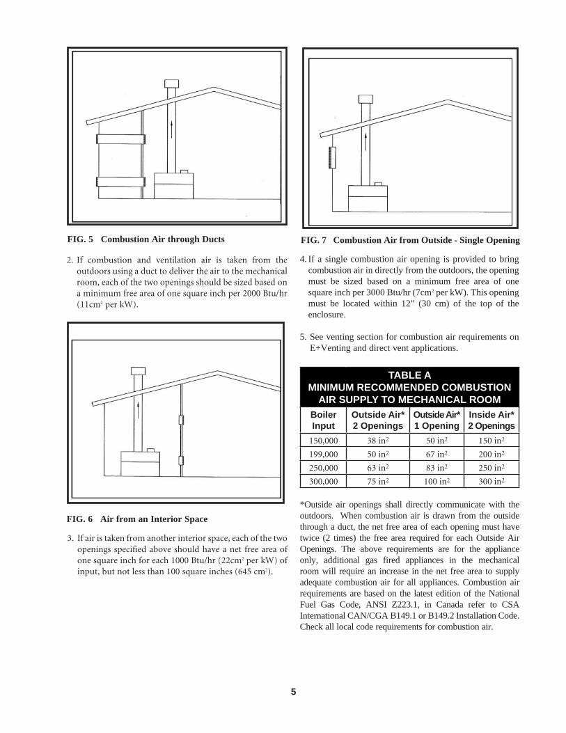
FIG. 27 Outdoor Kit Installed on Appliance
The Outdoor Kit
The required outdoor kit part numbers are listed by appliance size. The venting kit must be furnished by the manufacturer in accordance with CSA International and ANSI requirements. Each kit includes the outdoor vent cap / top assembly, gas valve cover assembly, deflectors, and weatherproof junction box assembly.
TABLE FOUTDOOR KITS
Input Btu/hr
Outdoor Kit w/ Pump Cover
Outdoor Kitwithout
Pump Cover150,000 ODK3062 ODK3069
199,999 ODK3063 ODK3070
250,000 ODK3067 ODK3071
300,000 ODK3068 ODK3072
Appliances which are shut down or will not operate may experience freezing due to convective air flow in the outdoor vent cap installed on the appliance. In cold climates, continuous pump operation or pump delay is recommended to help prevent freezing of water on outdoor systems. Proper freeze protection must be provided. See Freeze Protection.
� CAUTION
GAS SUPPLY
Verify appliance is supplied with type gas specified on rating plate. This appliance is orificed for operation up to 2000 feet altitude. The appliance will be derated 4% per 1000 feet above 2000 feet elevation. Consult the factory for installations above 2000 feet elevation. Field conversions for operation at high altitude must be performed by factory authorized personnel only. The appliance will be marked to indicate suitability for high altitude operation.
INLET GAS PRESSURE: Measured at the inlet pressure tap located upstream of the combination gas valve.
TABLE GINLET GAS PRESSURE
Natural Gas LP
Max. Water Column (Inches) 10.5" 13"
Min. Water Column (Inches) 4.0" 8"
Maximum inlet gas pressure must not exceed the value specified. Minimum value listed is for the purposes of input adjustment.
MANIFOLD PRESSURE: Measured at the pressure tap on the downstream side of the combination gas valve. The gas regulator on the appliance’s combination gas valve(s) is adjustable to supply proper manifold pressure for normal operation. If adjustment of regulator pressure is required, see Manifold Adjustment Procedure. Do not increase regulator pressure beyond specified pressure setting.
TABLE HNET MANIFOLD PRESSURE
Btu/hr Input150,000 - 300,000
Nat. Gas Regulator Setting1.8" w.c.
Btu/hr Input150,000 - 300,000
LP Gas Regulator Setting4.6" w.c.

24
TABLE FOUTDOOR KITS
Nominal Iron Pipe Size,
IN.Length of Pipe in Straight Feet
10 20 30 40 50 60 70 80 90 100 125 150 175 2003/4 369 256 205 174 155 141 128 121 113 106 95 86 79 74
1 697 477 384 328 292 267 246 256 210 200 179 164 149 1381 1/4 1,400 974 789 677 595 543 502 472 441 410 369 308 308 2871 1/2 2,150 1,500 1,210 1,020 923 830 769 707 666 636 564 472 472 441
2 4,100 2,820 2,260 1,950 1,720 1,560 1,440 1,330 1,250 1,180 1,100 974 871 8202 1/2 6,460 4,460 3,610 3,100 2,270 2,460 2,310 2,100 2,000 1,900 1,700 1,540 1,400 1,300
3 11,200 7,900 6,400 5,400 4,870 4,870 4,000 3,800 3,540 3,300 3,000 2,720 2,500 2,3404 23,500 16,100 13,100 11,100 10,000 10,000 8,300 7,690 7,380 7,380 6,150 5,640 5,130 4,720
Maximum Capacity of Pipe in Thousands of Btu/hr per hour for gas pressures of 14 Inches Water Column (0.5 PSIG) or less and a pressure drop of 0.5 Inch Water Column (Based on NAT GAS, 1025 Btu/hr per Cubic Foot of Gas and 0.60 Specific Gravity).
GAS PRESSURE TEST
1. The appliance must be disconnected from the gas supply piping system during any pressure testing of that system at a test pressure in excess of 1/2 PSIG (3.5 kPa).
2. The appliance must be isolated from the gas supply piping system by closing a manual shutoff valve during any pressure testing of the gas supply piping system at test pressures equal to or less than 1/2 PSIG (3.5 kPa).
3. The appliance and its gas connection must be leak-tested before placing it in operation.
GAS CONNECTION
1. Safe operation of appliance requires properly sized gas supply piping. See data below.
2. Gas pipe size may be larger than heater connection.
3. Installation of a union is suggested for ease of service.
4. Install a manual main gas shutoff valve, outside of the appliance gas connection and before the gas valve, when local codes require.
5. A trap (drip leg) MUST be provided in the inlet of the gas connection to the appliance.
6. The combination gas valve has an integral vent limiting device and does not require venting to atmosphere, outside the building. The appliance will not operate properly if the reference hose is removed or a vent to atmosphere is installed.
7. Optional gas controls may require routing of bleeds and vents to the atmosphere, outside the building when required by local codes.
8. Inlet gas connections to the gas valve is 3/4" NPT for the 150,000 through 300,000 Btu/hr models.
TABLE JSINGLE APPLIANCE INSTALLATIONS
SUGGESTED GAS PIPE SIZE
Input Btu/hr DISTANCE FROM METER
150,000 1" 1" 1 1/4" 1 1/2" 1 1/2"
199,999 1" 1" 1 1/4" 1 1/2" 2"
250,000 1" 1 1/4" 1 1/4" 1 1/2" 2"
300,000 1 1/4" 1 1/2" 1 1/2" 1 1/2" 2"

25
For each elbow or tee, add equivalent straight pipe to total length from table below.
TABLE K90° FITTINGS TO EQUIVALENT
STRAIGHT PIPEDiameter Pipe (Inches)
3/4" 1" 1 1/4" 1 1/2" 2" 3" 4" 5"
Equivalent Length of Straight Pipe (Feet)2" 2 1/2" 3 1/2" 4" 5" 10" 14" 20"
GAS PIPING
FIG. 28 Gas Piping to Heater
All gas connections must be made with pipe joint compound resistant to the action of liquefied petroleum and natural gases. All piping must comply with local codes and ordinances. Tubing installations must comply with approved standards and practices.
Install Piping to Control
1. The gas line should be a separate line direct from the meter unless the existing gas line is of sufficient capacity. Verify pipe size with your gas supplier.
2. Use new, properly threaded black iron pipe free from chips. If tubing is used, make sure the ends are square, deburred and clean. All tubing bends must be smooth and without deformation. Avoid flexible gas connections.
3. Run pipe or tubing to the control. If tubing is used, obtain a tube to pipe coupling to connect the tubing to the control.
4. Install a sediment trap in the supply line to the gas control.
5. Thread pipe the proper amount for insertion into gas valve. Effective length of standard 3/4” NPT thread is 9/16”, overall length of thread is 3/4”. DO NOT THREAD PIPE TOO FAR. Valve distortion or malfunction may result if the pipe is inserted too deeply.
6. Apply a moderate amount of good quality pipe compound (DO NOT use Teflon tape) to pipe only, leaving two end threads bare).
FIG. 29 Wrench to Support Gas Valve for Piping Connection
7. Remove seal over control inlet.
8. Connect pipe to control inlet. Use wrench to square ends of the control.
9. For LP gas, consult your LP gas supplier for expert installation.
10. Ensure that all air is properly bled from the gas line before starting the ignition sequence. Start-up without properly bleeding air from the gas line may require multiple reset functions of the ignition control module to achieve proper ignition.

26
4
3
2
0
1
2
3
1
4
MANOMETER
GAS VALVE
FIG. 30 Manometer Connection for Manifold Pressure Adjustments
FIG. 31 Manifold Gas Pressure Measurement
GAS MANIFOLD PRESSURE ADJUSTMENT PROCEDURE
IMPORTANT
The gas valve is referenced to the fan pressurized chamber by a hose connected from the vent of the gas valve regulator to the chamber pressure tap located on the left side of the jacket. Reference the drawings in this section for component location and connection points for pressure measurement. The referenced chamber pressure must be subtracted from the manifold pressure to obtain actual net manifold pressure for normal operation. A manometer or magnahelic gauge legible in 0.1" increments up to 10” water column is required to check and adjust the manifold pressure. The regulator cover screw on the gas valve must be in place and tight for the appliance to operate properly.
1. Turn the power switch to the “OFF” position.
2. Remove the top front jacket panel.
3. Locate the air pressure switch located to the right of the combustion air fan. Trace the hose from the air pressure switch to the barb located in the top of the upper chamber. Remove the hose from this barb and connect the hose from the manometer or magnahelic to this barb to measure the air pressure in the front chamber.
4. Turn the power switch to the “ON” position.
5. Set the thermostat to call for heat. The fan will start.
6. While the combustion air fan is running for the prepurge cycle and the pressure in the front chamber stabilizes, record the pressure in the front chamber. This pressure will be used to calculate the net manifold pressure.
7. Turn the power switch to the “OFF” position.
8. Remove the manometer or magnahelic hose from the front chamber barb and reinstall the hose from the air pressure switch to the barb.
9. Turn all gas valve knobs and the manual gas cock to the “OFF” position.
10. Remove the 1/8" hex plug, located on the “outlet” side of the gas valve and install a fitting suitable to connect to a manometer or magnahelic gauge (see Figure 31). Minimum range of scale should be up to 5" w.c. for natural gas and 10" w.c. for propane gas.
11. A reference pressure hose is factory installed from the barbed connection on the gas valve regulator to the fan pressurized front chamber. All manifold pressure measurements made with the reference hose in place will be the sum of the net manifold pressure and the air pressure in the front chamber.
12. Turn the power switch to the “ON” position.
13. Turn all gas valve knobs to the “ON” position.
14. Set the thermostat to call for heat.

27
15. Before the valve opens, the manometer or magnahelic gauge will read a positive air pressure of 1.4” w.c. to 1.8” w.c. in the jacket as supplied by the combustion air fan in the prepurge cycle. There is no gas flow at this point. This air pressure reading is normal.
16. The gas valve will open at the end of the trial for ignition stage and remain open as the burners fire. Observe the gas manifold pressure when valves open. If insufficient gas pressure is supplied to the burners, the burners will not fire. Record the gas pressure indicated on the manometer or magnahelic. Subtract the air pressure in the front chamber (as recorded in Step 6) from the gross manifold pressure observed at the end of trial for ignition and when the burners are firing. The gross manifold pressure will typically be within the range of 3.4” w.c. to 3.9” w.c. for Natural Gas and 6.1” w.c. to 6.7” w.c. for L.P. Gas at full fire. The difference in the gross manifold pressure and the front chamber pressure is the net manifold pressure setting of the gas valve’s regulator. Compare the net setting to the setting specified for the type of gas used. Adjust regulator as required. Set the thermostat to a setting lower than the appliance’s water temperature to turn the burners off. Allow appliance to run through the post purge sequence. Turn the power switch to the “OFF” position.
TABLE LNET MANIFOLD PRESSURE
REGULATOR PRESSURE LESSFRONT CHAMBER PRESSURE
Type of Gas Net Manifold Pressure Setting
Natural Gas 1.8" w.c.
LP Gas 4.6" w.c.
NOTE
The front chamber pressure must be subtracted from the gross regulator pressure to obtain actual net manifold pressure for normal operation. The front chamber pressure may vary based on elevation, stages of operation, vent length and model. For information on chamber pressure, see Combustion Air Adjustment. Do NOT increase net manifold pressure beyond the specified pressure setting.
17. If adjustment is necessary, remove the regulator cover screw on the gas valve.
18. Turn regulator adjustment screw clockwise to raise regulator gas pressure, counterclockwise to lower the regulator gas pressure. Turn regulator adjustment screw 1/4 turn in the desired rotation and cycle the
burners on in the sequence listed below and record the observed chamber and regulator settings. Subtract to determine the net manifold pressure setting. Repeat as necessary to achieve the specified net manifold pressure setting.
19. Replace cover screw on the regulator and turn the power switch to the “ON” position. Set the thermostat to call for heat. Observe gas regulator pressure again at the burner “ON” stages. Repeat this sequence until the proper regulator setting has been obtained.
NOTE
If the regulator cover screw it not in place and tight, the appliance will not function properly.
20. Turn the power switch to the “OFF” position.
21. Turn gas valves and manual gas cock knob to the “OFF” position.
22. Remove the gas pressure fitting from the gas valve and replace with the 1/8” hex plug (that was previously removed) and tighten.
23. Ensure that the chamber pressure reference hose is properly connected to the gas valve.
24. Turn the gas valve knobs to the “ON” position.
25. Turn the power switch to the “ON” position and replace the jacket panel. The appliance is now ready to operate.
If manifold pressure cannot be properly maintained, check gas supply pressure with a manometer connected to the inlet pressure tap on the gas control.

28
4
3
2
0
1
2
3
1
4
8
7
6
5
5
6
7
8
MANOMETER
GAS VALVE
FIG. 32 Manometer Connection for Gas Supply Pressure Measurement
CHECKING GAS SUPPLY PRESSURE
1. Turn the power switch and thermostat to “OFF” position.
2. Turn gas valve knob to “OFF” position.
3. Shut off gas supply at the manual valve in the gas piping to the appliance. If fuel supply is LP gas, shut off gas supply at the tank.
4. Remove the 1/8” hex plug, located on “inlet” side of the gas valve and install a fitting suitable to connect to a manometer or magnahelic gauge. Range of scale should be 14” w.c. or greater to check inlet pressure.
5. Turn on gas supply at the manual valve, turn on LP gas at tank if required.
6. Turn the power switch to “ON” position
7. Turn the gas valve knob to “ON” position
8. Set the thermostat to call for heat.
9. Observe the gas supply pressure as the burners are firing. Ensure inlet pressure is within specified range.
TABLE MMINIMUM AND MAXIMUM GAS SUPPLY
PRESSURES
Natural Gas LPG
Maximum Inches (water column)
10.5" w.c. 13" w.c.
Minimum Inches (water column)
4.0" w.c. 8" w.c.
10. If gas pressure is out of range, contact gas utility, gas supplier, qualified installer or service agency to determine necessary steps to provide proper gas pressure to the control.
11. If gas supply pressure is within normal range, proceed to remove gas manometer and replace pressure tap fittings in the gas control.
12. Turn the power switch and thermostat to “OFF” position.
13. Turn gas valve knob to “OFF” position.
14. Shut off gas supply at the manual valve in the gas piping to the appliance. If fuel supply is LP gas, shut off gas supply at the tank.
15. Remove the manometer and related fittings from “inlet” side of the gas valve, replace 1/8” hex plug in gas valve.
16. Turn on gas supply at the manual valve, turn on LP gas at tank if required.
17. Turn the power switch to “ON” position.
18. Turn the gas valve knob to “ON” position.
19. Set the thermostat to call for heat.
IMPORTANT
Upon completion of any testing on the gas system, leak test all connections with a soap solution while main burners are operating. Immediately repair any leak found in the gas train or related components. Do NOT operate an appliance with a leak in the gas train, valves or related piping.
Check burner performance by cycling the system while you observe burner response. Burners should ignite promptly. Flame pattern should be stable, see “Maintenance-Normal Flame Pattern.” Turn system off and allow burners to cool, then cycle burners again to ensure proper ignition and flame characteristics.

29
WATER CONNECTIONS
FIG. 33 Connection to the Appliance
Inlet and Outlet Connections
For ease of service, install unions on inlet and outlet of the appliance. The connection to the appliance marked “Inlet” on the header should be used for return from the system. The connection on the header marked “Outlet” is to be connected to the supply side of the system.
RELIEF VALVE
This appliance is supplied with a relief valve(s) sized in accordance with ASME Boiler and Pressure Vessel Code, Section IV (“Heating Boilers”). The relief valve(s) is installed in the vertical position and mounted in the hot water outlet. No valve is to be placed between the relief valve, and the appliance. To prevent water damage, the discharge from the relief valve shall be piped to a suitable floor drain for disposal when relief occurs. No reducing couplings or other restrictions shall be installed in the discharge line. The discharge line shall allow complete drainage of the valve and line. Relief valves should be manually operated at least once a year.
Avoid contact with hot discharge water.
� CAUTION
WATER FLOW SWITCH(IF EQUIPPED)
A water flow switch is available as a factory supplied option on 150,000 through 300,000 Btu/hr heating boilers and water heaters. The flow switch should be wired across the
X and B terminals on the appliance’s internal terminal strip. Remove the jumper between the terminals before connecting flow switch wires to the terminals. This wiring connection installs the flow switch in the 24 VAC safety circuit for the ignition control. A flow switch installed in 1 1/4” pipe requires a minimum flow of 10 GPM to make the flow switch and start burner operation. A flow switch installed in 1 1/2” pipe requires a minimum flow of 13 GPM to make the flow switch and start burner operation. A flow switch installed in 2” pipe requires a minimum flow of 19 GPM to make the flow switch and start burner operation. A water flow switch meets most code requirements for a low-water cut off device on boilers requiring forced circulation for operation.
FIG. 34 Water Flow Switch
LOW WATER CUTOFF(IF EQUIPPED)
A hot water supply boiler installed above radiation level must be provided with a low water cutoff device either as part of the appliance or at the time of installation.
An electronic or float type low water cut off is available as a factory supplied option on all appliances. Low water cutoffs should be inspected every six months, including flushing of float types.
COMBINATION GAS VALVE
Each appliance has a combination gas valve to cycle the gas upply on and off to the burners. The combination valve consists of a gas regulator and two valve seats to meet the requirements for redundant gas valves. The valve has a gas control knob that must remain in the open position at all times when the appliance is in service. The gas control valve has pressure taps located on the inlet and discharge sides of the valve. Manifold pressure is adjusted using the regulator located on the valve.
The manifold pressure is preset at the factory and adjustment is not usually required. If the manifold pressure is to be adjusted, follow the “Gas Manifold Pressure Adjustment Procedure” for proper adjustment.
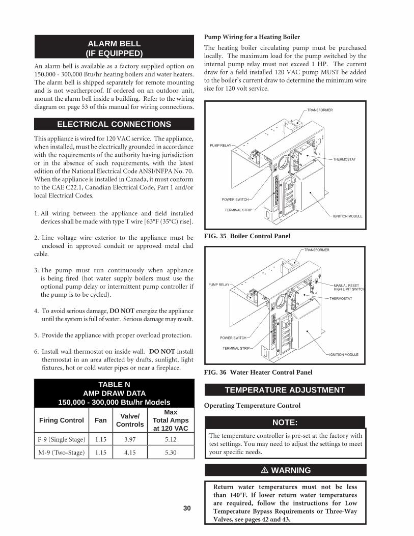
30
ALARM BELL(IF EQUIPPED)
An alarm bell is available as a factory supplied option on 150,000 - 300,000 Btu/hr heating boilers and water heaters. The alarm bell is shipped separately for remote mounting and is not weatherproof. If ordered on an outdoor unit, mount the alarm bell inside a building. Refer to the wiring diagram on page 53 of this manual for wiring connections.
ELECTRICAL CONNECTIONSThis appliance is wired for 120 VAC service. The appliance, when installed, must be electrically grounded in accordance with the requirements of the authority having jurisdiction or in the absence of such requirements, with the latest edition of the National Electrical Code ANSI/NFPA No. 70. When the appliance is installed in Canada, it must conform to the CAE C22.1, Canadian Electrical Code, Part 1 and/or local Electrical Codes.
1. All wiring between the appliance and field installed devices shall be made with type T wire [63°F (35°C) rise].
2. Line voltage wire exterior to the appliance must be enclosed in approved conduit or approved metal clad cable.
3. The pump must run continuously when appliance is being fired (hot water supply boilers must use the optional pump delay or intermittent pump controller if the pump is to be cycled).
4. To avoid serious damage, DO NOT energize the appliance until the system is full of water. Serious damage may result.
5. Provide the appliance with proper overload protection.
6. Install wall thermostat on inside wall. DO NOT install thermostat in an area affected by drafts, sunlight, light fixtures, hot or cold water pipes or near a fireplace.
TABLE NAMP DRAW DATA
150,000 - 300,000 Btu/hr Models
Firing Control Fan Valve/Controls
MaxTotal Ampsat 120 VAC
F-9 (Single Stage) 1.15 3.97 5.12
M-9 (Two-Stage) 1.15 4.15 5.30
Pump Wiring for a Heating Boiler
The heating boiler circulating pump must be purchased locally. The maximum load for the pump switched by the internal pump relay must not exceed 1 HP. The current draw for a field installed 120 VAC pump MUST be added to the boiler’s current draw to determine the minimum wire size for 120 volt service.
FIG. 35 Boiler Control Panel
FIG. 36 Water Heater Control Panel
TEMPERATURE ADJUSTMENT
Operating Temperature Control
The temperature controller is pre-set at the factory with test settings. You may need to adjust the settings to meet your specific needs.
NOTE:
Return water temperatures must not be less than 140°F. If lower return water temperatures are required, follow the instructions for Low Temperature Bypass Requirements or Three-Way Valves, see pages 42 and 43.
� WARNING
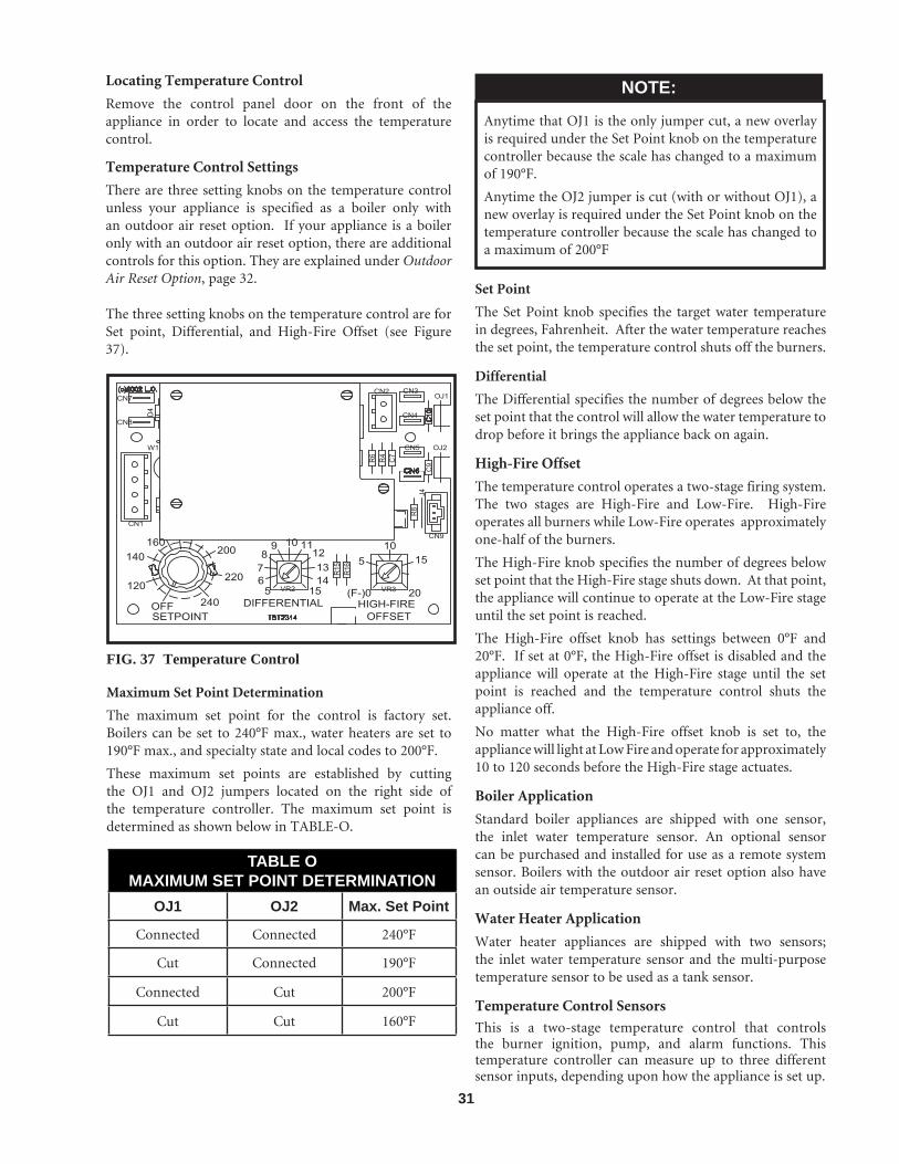
31
Locating Temperature Control
Remove the control panel door on the front of the appliance in order to locate and access the temperature control.
Temperature Control Settings
There are three setting knobs on the temperature control unless your appliance is specified as a boiler only with an outdoor air reset option. If your appliance is a boiler only with an outdoor air reset option, there are additional controls for this option. They are explained under Outdoor Air Reset Option, page 32.
The three setting knobs on the temperature control are for Set point, Differential, and High-Fire Offset (see Figure 37).
FIG. 37 Temperature Control
Maximum Set Point Determination
The maximum set point for the control is factory set. Boilers can be set to 240°F max., water heaters are set to 190°F max., and specialty state and local codes to 200°F.
These maximum set points are established by cutting the OJ1 and OJ2 jumpers located on the right side of the temperature controller. The maximum set point is determined as shown below in TABLE-O.
TABLE OMAXIMUM SET POINT DETERMINATION
OJ1 OJ2 Max. Set Point
Connected Connected 240°F
Cut Connected 190°F
Connected Cut 200°F
Cut Cut 160°F
Anytime that OJ1 is the only jumper cut, a new overlay is required under the Set Point knob on the temperature controller because the scale has changed to a maximum of 190°F.
Anytime the OJ2 jumper is cut (with or without OJ1), a new overlay is required under the Set Point knob on the temperature controller because the scale has changed to a maximum of 200°F
NOTE:
Set Point
The Set Point knob specifies the target water temperature in degrees, Fahrenheit. After the water temperature reaches the set point, the temperature control shuts off the burners.
Differential
The Differential specifies the number of degrees below the set point that the control will allow the water temperature to drop before it brings the appliance back on again.
High-Fire Offset
The temperature control operates a two-stage firing system. The two stages are High-Fire and Low-Fire. High-Fire operates all burners while Low-Fire operates approximately one-half of the burners.
The High-Fire knob specifies the number of degrees below set point that the High-Fire stage shuts down. At that point, the appliance will continue to operate at the Low-Fire stage until the set point is reached.
The High-Fire offset knob has settings between 0°F and 20°F. If set at 0°F, the High-Fire offset is disabled and the appliance will operate at the High-Fire stage until the set point is reached and the temperature control shuts the appliance off.
No matter what the High-Fire offset knob is set to, the appliance will light at Low Fire and operate for approximately 10 to 120 seconds before the High-Fire stage actuates.
Boiler Application
Standard boiler appliances are shipped with one sensor, the inlet water temperature sensor. An optional sensor can be purchased and installed for use as a remote system sensor. Boilers with the outdoor air reset option also have an outside air temperature sensor.
Water Heater Application
Water heater appliances are shipped with two sensors; the inlet water temperature sensor and the multi-purpose temperature sensor to be used as a tank sensor.
Temperature Control Sensors
This is a two-stage temperature control that controls the burner ignition, pump, and alarm functions. This temperature controller can measure up to three different sensor inputs, depending upon how the appliance is set up.

32
They are as follows:
1. Inlet Water Temperature Sensor
2. Multi-Purpose Temperature Sensor
3. Outside Air Temperature Sensor
Inlet Water Temperature Sensor
This sensor measures the inlet water temperature coming into the appliance.
Multi-Purpose Temperature Sensor
Depending upon how your appliance is set up, this sensor can be used as a system sensor in a boiler system or a tank sensor for water heater applications. Connect this sensor to the two blue wires in the upper left-hand corner of the control panel.
Outdoor Air Temperature Sensor
The outside air temperature sensor will only be used for boiler systems. The outside air sensor is optional. This sensor allows you to tie boiler operation to the outdoor air temperature. As outside temperatures drop, the control will increase the temperature setting of the boiler. As outdoor temperatures rise, the control will decrease the temperature to the selected set point of the boiler. You can set the control to shut the boiler off when a desired outdoor air temperature level is reached.
You must purchase the sensor from the appliance manufacturer. The sensor comes with a housing that helps protect the sensor from the elements. Mount the air sensor housing under the eve of the roof. Make sure the housing is out of direct sunlight. This will ensure that the sensor will accurately read the true outdoor temperature. Connect the outdoor air temperature sensor to the terminal block on the outdoor air reset board. For more information on mounting the sensor, see Remote Mounting of Sensors, this page.
Placement of Sensors
Inlet Temperature Sensor
The inlet water temperature sensor is placed into the inlet bulbwell on the boiler. This sensor is installed by the factory in new appliances. Make sure to insert the sensor all the way into the bulbwell, leaving no air pocket between the front surface of the sensor and the back of the bulbwell. Air pockets are thermally non-conductive and will cause sensors to read inaccurately.
System Sensor
The system sensor is used for boiler applications. This sensor will control the boiler operation based upon the water temperature within the building loop.
Tank Sensor
The tank sensor is used in water heating applications. Place the sensor in a water storage tank to measure water temperature. For more information on mounting the sensor, see Remote Mounting of Sensors this page.
Remote Mounting of Sensors
You must mount the outside air temperature sensor outside the building. To mount remote sensors, follow the guidelines listed on this page. Take care to correctly wire sensors to the appliance. Erratic temperature readings can be caused by poor wiring practices. Twist the wires between the appliance and the remote sensor. Turn wires at least three or four turns per linear foot of wiring. This provides protection against some types of electrical interferences.
1. Do not route temperature sensor wiring with building power wiring.
2. Do not locate temperature sensor wiring next to control contactors.
3. Do not locate temperature sensor wiring near electric motors.
4. Do not locate temperature sensor wiring near welding equipment.
5. Make sure good mechanical connections are made to the sensor, any interconnecting wiring and the controller.
6. Do not mount sensor with leadwire end pointing up in an area where condensation can occur.
7. Use shielded wiring to connect the sensor to the control when the possibility of an electrically noisy environment exists. Shielded cable is recommended on all cable runs of more than 25 feet in length.
Ground the cable shield at the connection to the boiler temperature control only. Do not ground the shielded cable at the sensor end.
To maintain temperature accuracy, sensor wires should be 18 AWG two conductor (18/2). Use shielded wire if required.
NOTE:
Outdoor Air Reset Option
For boilers ordered with the Outdoor Air Reset option, there is an additional control (FIG. 38). There are three setting knobs for Shutdown, Outdoor Air Max., and Ratio. There is also a switch to turn the outdoor air shutdown feature On or Off. An O.A. Sensor is also included.
OUTDOOR AIR RESET OPTION

33
R4
R4
R6
R6
R8
R8
R16
R16
R15
R15
C7
C7
C9
C9
C10
C10
VR2VR2 VR3VR3
OJ1OJ1
OJ2OJ2D
4D
4
J4J4
CN1CN1
CN2CN2
CN9CN9
CN7CN7
CN8CN8
CN3CN3
CN4CN4
CN5CN5
CN6CN6
W1W1
TST2314TST2314
2020
15151010
55
(F-)0(F-)0151514141313
121211111099
887766
55OFFOFF
120120240240
220220
200200160160
140140
SETPOINTSETPOINTDIFFERENTIALDIFFERENTIAL HIGH-FIREHIGH-FIRE
OFFSETOFFSET
(c)2002 L.C.(c)2002 L.C.
SHUTDOWN
45
50
45 1.3
O.A. MAX.7040
VR1
65
RATIO
VR20.6
0.5
0.71.4
1.5 W1 W2
W3
6050
7040
5560
VR3
65
DISABLEO.A. SHUTDOWN
1.00.90.8 1.2
1.1
O.A. SENSORENABLEON
SW1
55 CN1
FIG. 38 Optional Outdoor Air Reset Control FIG. 39 Outdoor Air Control Example Chart
Shutdown
The Shutdown knob specifies the outdoor air lockout temperature at which the control would prevent the appliance from operating.
Outdoor Air Max (O.A. Max)
The O.A. Max knob allows a reset up to the maximum outdoor air temperature specified by this knob setting. When the outdoor air temperature is above the specified setting, the unit will not function in the O.A. Reset Mode, but will continue to run at the selected set point temperature.
Note that the set point knob will now indicate the “minimum” boiler temperature. Target temperature is determined by the ratio and outdoor air temperature below the O.A. Max setting.
Ratio
The Ratio knob allows control over the reset ratio to be used during Outdoor Air Reset. The allowable ratios are as low as 0.5:1 or as high as 1.5:1.
Selecting the 0.5:1 ratio will increase the set point 0.5°F for every 1.0°F drop in outdoor air temperature up to the maximum set point temperature.
Selecting the 1.5:1 ratio will increase the set point 1.5°F for every 1.0°F drop in outdoor air temperature up to the maximum set point temperature.
See Figure 39 for an outdoor air reset chart example.
Outdoor Air Shutdown Enable/Disable Switch
The Outdoor Air Shutdown Enable/Disable switch turns the outdoor air shutdown feature On and Off. Disabling the Outdoor Air Shutdown feature allows the appliance to operate regardless of the outdoor air temperature. This is needed for indirect domestic hot water systems for example.
ADDITIONAL TEMPERATURECONTROLS
High Water Temperature Limit Control
The appliance is equipped with a fixed setting, auto-reset high water temperature limit control. The heating boiler temperature limit control has a fixed limit setting of 240°F (115°C); the water heater temperature limit control has a fixed limit setting of 200°F (93°C). If water temperature exceeds the set point, the limit will break the control circuit and shut down the appliance. The limit control will only be reset after the water temperature has cooled below the set point of the limit. The high water temperature limit control is mounted in the outlet side of the front header.
Manual Reset High Water Temperature Limit Control (Standard on Water Heaters and Optional on Boilers)
The appliance may be optionally equipped with a fixed setting, manual reset high water temperature limit control. This manual reset temperature limit control has a fixed limit setting of 230°F (110°C). If water temperature exceeds this set point, the limit will break the control circuit and shut down the appliance. The limit control can only be reset after the water temperature has cooled below the set point of the limit. Reset of the limit control is accomplished by pushing the Red Reset Button located on the control.
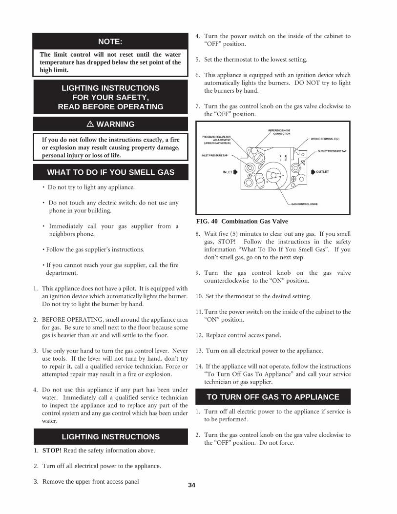
34
WHAT TO DO IF YOU SMELL GAS
NOTE: The limit control will not reset until the water temperature has dropped below the set point of the high limit.
LIGHTING INSTRUCTIONSFOR YOUR SAFETY,
READ BEFORE OPERATING
If you do not follow the instructions exactly, a fire or explosion may result causing property damage, personal injury or loss of life.
� WARNING
• Do not try to light any appliance.
• Do not touch any electric switch; do not use any phone in your building.
• Immediately call your gas supplier from a neighbors phone.
• Follow the gas supplier’s instructions.
• If you cannot reach your gas supplier, call the fire department.
1. This appliance does not have a pilot. It is equipped with an ignition device which automatically lights the burner. Do not try to light the burner by hand.
2. BEFORE OPERATING, smell around the appliance area for gas. Be sure to smell next to the floor because some gas is heavier than air and will settle to the floor.
3. Use only your hand to turn the gas control lever. Never use tools. If the lever will not turn by hand, don’t try to repair it, call a qualified service technician. Force or attempted repair may result in a fire or explosion.
4. Do not use this appliance if any part has been under water. Immediately call a qualified service technician to inspect the appliance and to replace any part of the control system and any gas control which has been under water.
LIGHTING INSTRUCTIONS1. STOP! Read the safety information above.
2. Turn off all electrical power to the appliance.
3. Remove the upper front access panel
4. Turn the power switch on the inside of the cabinet to “OFF” position.
5. Set the thermostat to the lowest setting.
6. This appliance is equipped with an ignition device which automatically lights the burners. DO NOT try to light the burners by hand.
7. Turn the gas control knob on the gas valve clockwise to the “OFF” position.
FIG. 40 Combination Gas Valve
8. Wait five (5) minutes to clear out any gas. If you smell gas, STOP! Follow the instructions in the safety information “What To Do If You Smell Gas”. If you don’t smell gas, go on to the next step.
9. Turn the gas control knob on the gas valve counterclockwise to the “ON” position.
10. Set the thermostat to the desired setting.
11. Turn the power switch on the inside of the cabinet to the “ON” position.
12. Replace control access panel.
13. Turn on all electrical power to the appliance.
14. If the appliance will not operate, follow the instructions “To Turn Off Gas To Appliance” and call your service technician or gas supplier.
TO TURN OFF GAS TO APPLIANCE
1. Turn off all electric power to the appliance if service is to be performed.
2. Turn the gas control knob on the gas valve clockwise to the “OFF” position. Do not force.

35
TABLE - PIGNITION MODULE
INDICATING LIGHTS
Should overheating occur or the gas fail to shut off, turn off the manual gas control valve to the appliance.
� WARNING
IGNITION SYSTEM CHECKOUT
1. Turn off gas supply to appliance.
2. Turn thermostat to highest setting.
3. Turn electric power on.
4. The ignition module will lock out and the LED will blink.
5. Readjust thermostat to normal setting.
6. Turn on gas supply.
7. Turn power off then on again to reset ignition module.
8. If ignition system fails to operate properly, repair work must be performed by a qualified serviceman or installer.
HOT SURFACE IGNITION SYSTEM
The hot surface ignition module is not repairable. Any modification or repairs will invalidate the warranty and may create hazardous conditions that result in property damage, personal injury, fire, explosion and/or toxic gases. A faulty ignition module must be replaced with a new unit. The hot surface igniter is also the flame sensor.
OPERATION AND DIAGNOSTIC LIGHTS
The unit has a lighted ON/OFF power switch on the outer cabinet (left side) and five (5) LED indicators on the electronic ignition control module to monitor the units operation.
Indicating Lights FunctionPower ON Switch - ON - 120 VAC supplied to unit
Power LED
-ON - Module is powered from 24 VAC system and operating properly-Blinks continuously if voltage is too high on transformer secondary-OFF - Module is not powered
Purge LED
- OFF - Combustion air fan is not powered OR air fl ow is not proven- ON - When the unit is in prepurge or interpurge- Blinks continuously when there is a pressure switch fault
Ignitor LED- OFF - Ignitor is off- ON - When hot surface ignitor is on
Valve LED
- OFF - Gas valve is closed- ON - Control signaling gas valve is on- Blinks continuously when control is in LOCKOUT because it failed ignition
Flame LED
- OFF - Flame is not present- ON - Control signaling fl ame is present- Blinks continuously when L1 and neutral are reversed

36
FREEZE PROTECTION
1. For water heaters, and boilers with the pump delay option, if either the inlet sensor or the optional multi-purpose temperature sensor reads below 40°F, the pump relay will turn ON. When the temperature rises above 50°F the pump relay will turn OFF.
2. Location - Heating boilers and water heaters must be located in a room having a temperature safely above freezing [32°F(0°C].
3. Caution - A room where the appliance is installed and operating under a negative pressure may experience a downdraft in the flue of an appliance which is not firing. The cold outside air pulled down the flue may freeze a heat exchanger. This condition must be corrected to provide adequate freeze protection.
4. Freeze protection for a heating boiler or hot water supply boiler using an indirect coil can be provided by using hydronic system antifreeze. Follow the manufacturer’s instructions. DO NOT use undiluted or automotive type antifreeze.
5. A snow screen should be installed to prevent snow and ice accumulation around the appliance venting system in cold climates.
6. Shut-down and Draining - If for any reason, the appliance is to be shut off, the following precautionary measures must be taken:
a. Shut off gas supply.
b. Shut off water supply.
c. Shut off electrical supply.
d. Drain the appliance completely. Remove one threaded plug or bulb well from the inlet side of the front header and one from the outlet side of the front header on the heat exchanger. Blow all water out of the heat exchanger.
e. Drain pump and piping.
FREEZE PROTECTION FOR A HEATING BOILER SYSTEM
(If Required)
1. Use only properly diluted inhibited glycol antifreeze designed for hydronic systems. Inhibited propylene glycol is recommended for systems where incidental contact with drinking water is possible.
DO NOT use undiluted or automotive type antifreeze.
� CAUTION
2. A solution of 50% antifreeze will provide maximum protection of approximately -30°F.
3. Follow the instructions from the antifreeze manufacturer. Quantity of antifreeze required based on total system volume including expansion tank volume.
4. Glycol is denser than water and changes the viscosity of the system. The addition of glycol will decrease heat transfer and increase frictional loss in the boiler and related piping. A larger pump with more capacity may be required to maintain desired flow rates in a glycol system.
5. Local codes may require a back flow preventer or actual disconnect from city water supply when antifreeze is added to the system.
WATER TREATMENT
In hard water areas, water treatment should be used to reduce the introduction of minerals to the system. Minerals in the water can collect in the heat exchanger tubes and cause noise on operation. Excessive build up of minerals in the heat exchanger can cause a non-warrantable failure.
MAINTENANCE
Listed below are items that must be checked to ensure safe reliable operations. Verify proper operation after servicing.
Label all wires prior to disconnection when servicing controls. Wiring erros can cause improper and dangerous operation.
� CAUTION
1. Examine the venting system at least once a year. Check more often in first year to determine inspection interval. Check all joints and pipe connections for tightness, corrosion or deterioration. Clean screens in the venting air intake system as required. Have the entire system, including the venting system, periodically inspected by a qualified service agency.
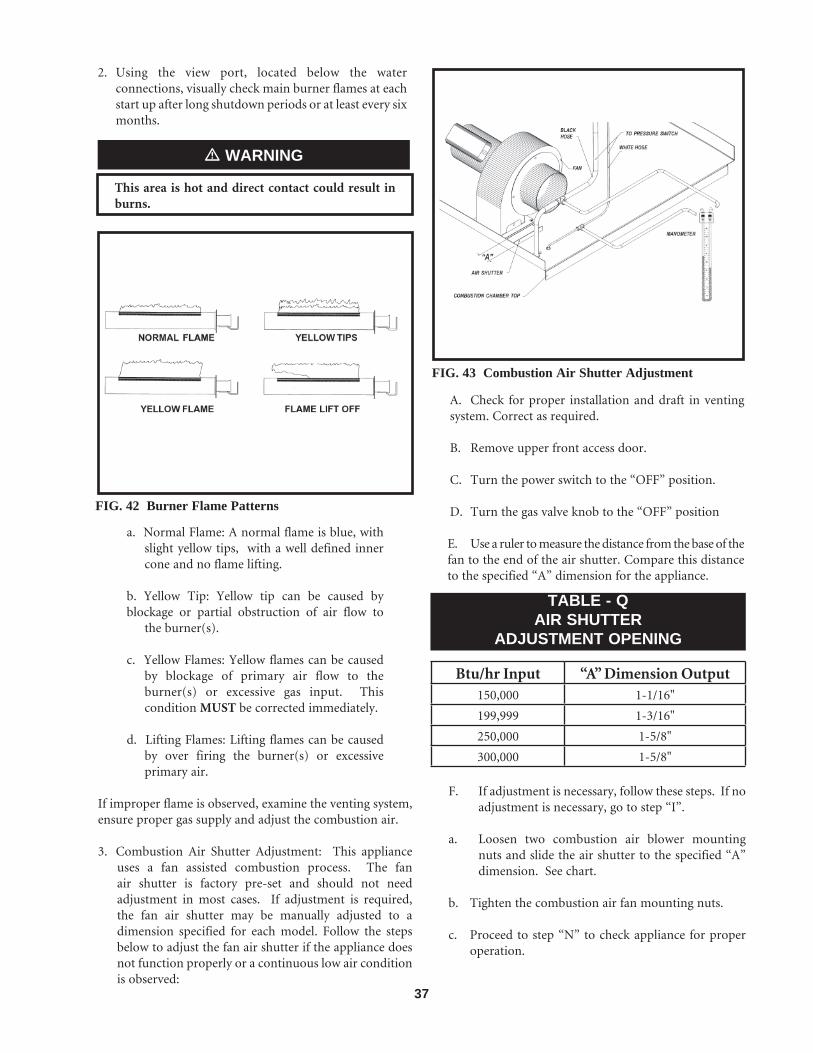
37
2. Using the view port, located below the water connections, visually check main burner flames at each start up after long shutdown periods or at least every six months.
This area is hot and direct contact could result in burns.
� WARNING
a. Normal Flame: A normal flame is blue, with slight yellow tips, with a well defined inner cone and no flame lifting.
b. Yellow Tip: Yellow tip can be caused by blockage or partial obstruction of air flow to the burner(s).
c. Yellow Flames: Yellow flames can be caused by blockage of primary air flow to the burner(s) or excessive gas input. This condition MUST be corrected immediately.
d. Lifting Flames: Lifting flames can be caused by over firing the burner(s) or excessive primary air.
If improper flame is observed, examine the venting system, ensure proper gas supply and adjust the combustion air.
3. Combustion Air Shutter Adjustment: This appliance uses a fan assisted combustion process. The fan air shutter is factory pre-set and should not need adjustment in most cases. If adjustment is required, the fan air shutter may be manually adjusted to a dimension specified for each model. Follow the steps below to adjust the fan air shutter if the appliance does not function properly or a continuous low air condition is observed:
FIG. 42 Burner Flame Patterns
FIG. 43 Combustion Air Shutter Adjustment
A. Check for proper installation and draft in venting system. Correct as required.
B. Remove upper front access door.
C. Turn the power switch to the “OFF” position.
D. Turn the gas valve knob to the “OFF” position
E. Use a ruler to measure the distance from the base of the fan to the end of the air shutter. Compare this distance to the specified “A” dimension for the appliance.
TABLE - QAIR SHUTTER
ADJUSTMENT OPENING
Btu/hr Input “A” Dimension Output150,000 1-1/16"
199,999 1-3/16"
250,000 1-5/8"
300,000 1-5/8"
F. If adjustment is necessary, follow these steps. If no adjustment is necessary, go to step “I”.
a. Loosen two combustion air blower mounting nuts and slide the air shutter to the specified “A” dimension. See chart.
b. Tighten the combustion air fan mounting nuts.
c. Proceed to step “N” to check appliance for proper operation.

38
G. If the appliance does not function properly after manually setting the air shutter, use a magnahelic or slope gauge to set the air shutter based on differential air pressure.
H. Install a tee in each of the hoses connecting the chamber pressure and burner venturi pressure to the pressure switch. Install a connecting hose from the branch of each tee to a manometer, magnahelic or slope gauge, legible in 0.1" increments up to 3" w.c. Connect chamber pressure to the positive pressure side of the gauge and burner venturi pressure to the negative side of the gauge.
I. Turn the power switch to “ON” position. Combustion air fan should start. Leave the gas valve “OFF”.
J. With the combustion air fan running, the gauge will read a system differential pressure. The proper differential pressure should be in the following range, depending upon length of pipe used:
TABLE - RDIFFERENTIAL AIR PRESSURE
Btu/hr Input Differential Pressure150,000 1.4 - 1.8" w.c.
199,999 1.4 - 1.8" w.c.
250,000 1.5 - 1.9" w.c.
300,000 1.5 - 1.9" w.c.
K. If adjustment is necessary, follow these steps. If no adjustment is necessary, go to step “L”.
a. Loosen two combustion air blower mounting nuts, to allow the air shutter to slide. See Figure 43.
b. If differential pressure needs increasing, pull the air shutter out with thumb and finger gradually and evenly. Push in the air shutter to decrease differential pressure.
c. If the differential pressure cannot be obtained, shut the appliance down and inspect the vent system (both air and flue gas passageways) for obstructions or leaks.
d. Tighten combustion air blower mounting nuts.
L. Turn the power switch to “OFF” position.
M. Remove gauge and tee connections, ensuring connections are made at the pressure switch correctly; the chamber pressure to the connection and the burner venturi pressure to the connection.
N. Turn the gas valve knob to “ON” position.
O. Turn the power switch to “ON” position.
P. Replace upper front access door.
Q. When the main burner lights, observe the burner flame through observation port. Flames should be light blue in color with slight yellow tips; flames should be settled on burner head with no lifting.
R. The appliance is now ready to operate.
BURNER REMOVAL
The combustion chamber lining in this appliance contains ceramic fiber materials. Ceramic fibers can transform into cristobalite (crystalline silica) when exposed to temperatures above 2192°F (1200°C) dependent upon the length of exposure time.*
The International Agency for Research on Cancer (I.A.R.C.) has concluded, “Crystalline silica inhaled in the form of quartz or cristobalite from occupational sources is carcinogenic to humans.”**
Testing has confirmed that the ceramic fibers in this application do not reach 2192°F (1200°C).
*Reference Dyson, D., Butler, M., Hughes, R., Fisher, R., and Hicks, G. The Devitrification of Alumino-silicate Ceramic Fiber Materials - The Kinetics of the Formation of Different Crystalline Phases, Ann. Occup. Hyg. Vol. 41, No. 55, 1997.**Reference I.A.R.C. Monograph 68, June 1997.
� WARNING
The ceramic fiber material used in this appliance is an irritant; when handling or replacing the ceramic materials it is advisable that the installer follow these safety guides.
NOTE:

39
REMOVAL OF COMBUSTION CHAMBER LINING OR BASE PANELS:• Avoid breathing dust and contact with skin and eyes.• Use NIOSH certified dust respirator (N95) (http://www.cdc.gov/niosh/hompage.html).• Lightly mist with water (only those areas being handled) the combustion chamber lining or base insulation to prevent airborne fibers.• Remove combustion chamber lining or base insulation from the boiler and place it in a plastic bag for disposal.• Wash potentially contaminated clothes separately from other clothing. Rinse clothes thoroughly.• NIOSH stated First Aid: Eye: Irrigate immediately. Breathing: Fresh air.
4. Flue Gas Passageways Cleaning Procedures: Any sign of soot at burners indicates a need for cleaning. The following cleaning procedure must only be performed by a qualified serviceman or installer. Proper service is required to maintain safe operation. Properly installed and adjusted appliances seldom need flue cleaning.
All gaskets on disassembled components must be replaced with new gaskets on reassembly. Gasket kits are available from your distributor.
a. Turn off main power to appliance.
b. Turn off main manual gas shutoff to appliance.
c. Remove the front outer jacket panels.
d. Remove gas valve from the manifold.
e. Remove screws from manifold mounting brackets. Pull manifold(s)/ orifice assembly away from burners. Remove hose from burner tap.
f. Remove mounting screws from each burner and slide burner out toward front of appliance. Use caution to prevent damage to burner gaskets, refractory, hot surface igniter or wiring.
g. Remove soot from burners with a stiff bristle brush. Damaged burners or burner gaskets must be replaced.
HEAT EXCHANGER CLEANING
5. Check the heat exchanger surface for sooting. If present, heat exchanger must be cleaned and problem corrected. Proceed as follows.
a. Remove manifold/orifice assembly as described in steps “a” through “e” in “Burner Removal”.
b. Disconnect wiring from hot surface igniter and hose from burner tap.
c. Remove inner combustion chamber door mounting screws, tilt slightly and slide door assembly out toward front of appliance. Use caution to prevent damage to refractory, hot surface igniter, hose and wiring.
d. Check “V” baffles on top of heat exchanger. Remove and clean if necessary.
e. Remove soot from heat exchanger with a stiff bristle brush. Use a vacuum to remove loose soot from surfaces and inner chamber.
f. Carefully reinstall combustion chamber door, jacket panels, dividers, burners, manifolds wires and hoses. Use new gasket material for proper air seal.
g. Reassemble and test for gas leaks.
h. Cycle appliance and check for proper operation.
An appliance installed in a dust or dirt contaminated atmosphere will require cleaning of the burners on a 3 to 6 month schedule or more often, based on severity of contamination. Contaminants can be drawn in with the combustion air. Non-combustible particulate matter such as dust, dirt, concrete dust or dry wall dust can block burner ports and cause non-warrantable failure Use extreme care when operating an appliance for temporary heat during new construction. The burners and fan will probably require a thorough cleaning before the appliance is placed in service.
6. Combustion Air Fan: The combustion air fan should be checked every 6 months. Clean as required when installed in a dust or dirt contaminated location.
7. Water Circulating Pump: Inspect pump every 6 months and oil as necessary. Use SAE 30 non-detergent oil or lubricant specified by pump manufacturer.
8. Keep appliance area clear and free from combustible materials, gasoline and other flammable vapors and liquids.
9. Check frequently to be sure the flow of combustion and ventilation air to the boiler is not obstructed.
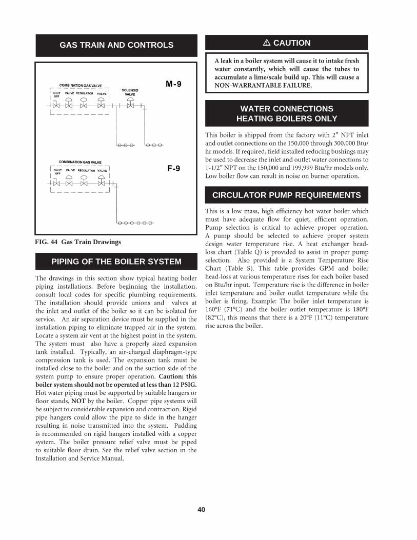
40
GAS TRAIN AND CONTROLS
FIG. 44 Gas Train Drawings
The drawings in this section show typical heating boiler piping installations. Before beginning the installation, consult local codes for specific plumbing requirements. The installation should provide unions and valves at the inlet and outlet of the boiler so it can be isolated for service. An air separation device must be supplied in the installation piping to eliminate trapped air in the system. Locate a system air vent at the highest point in the system. The system must also have a properly sized expansion tank installed. Typically, an air-charged diaphragm-type compression tank is used. The expansion tank must be installed close to the boiler and on the suction side of the system pump to ensure proper operation. Caution: this boiler system should not be operated at less than 12 PSIG. Hot water piping must be supported by suitable hangers or floor stands, NOT by the boiler. Copper pipe systems will be subject to considerable expansion and contraction. Rigid pipe hangers could allow the pipe to slide in the hanger resulting in noise transmitted into the system. Padding is recommended on rigid hangers installed with a copper system. The boiler pressure relief valve must be piped to suitable floor drain. See the relief valve section in the Installation and Service Manual.
PIPING OF THE BOILER SYSTEM
A leak in a boiler system will cause it to intake fresh water constantly, which will cause the tubes to accumulate a lime/scale build up. This will cause a NON-WARRANTABLE FAILURE.
� CAUTION
WATER CONNECTIONSHEATING BOILERS ONLY
This boiler is shipped from the factory with 2” NPT inlet and outlet connections on the 150,000 through 300,000 Btu/hr models. If required, field installed reducing bushings may be used to decrease the inlet and outlet water connections to 1-1/2” NPT on the 150,000 and 199,999 Btu/hr models only. Low boiler flow can result in noise on burner operation.
CIRCULATOR PUMP REQUIREMENTS
This is a low mass, high efficiency hot water boiler which must have adequate flow for quiet, efficient operation. Pump selection is critical to achieve proper operation. A pump should be selected to achieve proper system design water temperature rise. A heat exchanger head-loss chart (Table Q) is provided to assist in proper pump selection. Also provided is a System Temperature Rise Chart (Table S). This table provides GPM and boilerhead-loss at various temperature rises for each boiler based on Btu/hr input. Temperature rise is the difference in boiler inlet temperature and boiler outlet temperature while the boiler is firing. Example: The boiler inlet temperature is 160°F (71°C) and the boiler outlet temperature is 180°F (82°C), this means that there is a 20°F (11°C) temperature rise across the boiler.
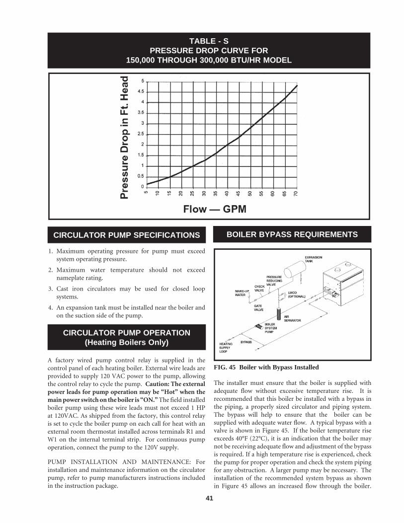
41
TABLE - SPRESSURE DROP CURVE FOR
150,000 THROUGH 300,000 BTU/HR MODEL
CIRCULATOR PUMP SPECIFICATIONS
CIRCULATOR PUMP OPERATION(Heating Boilers Only)
1. Maximum operating pressure for pump must exceed system operating pressure.
2. Maximum water temperature should not exceed nameplate rating.
3. Cast iron circulators may be used for closed loop systems.
4. An expansion tank must be installed near the boiler and on the suction side of the pump.
A factory wired pump control relay is supplied in the control panel of each heating boiler. External wire leads are provided to supply 120 VAC power to the pump, allowing the control relay to cycle the pump. Caution: The external power leads for pump operation may be “Hot” when the main power switch on the boiler is “ON.” The field installed boiler pump using these wire leads must not exceed 1 HP at 120VAC. As shipped from the factory, this control relay is set to cycle the boiler pump on each call for heat with an external room thermostat installed across terminals R1 and W1 on the internal terminal strip. For continuous pump operation, connect the pump to the 120V supply.
PUMP INSTALLATION AND MAINTENANCE: For installation and maintenance information on the circulator pump, refer to pump manufacturers instructions included in the instruction package.
BOILER BYPASS REQUIREMENTS
FIG. 45 Boiler with Bypass Installed
The installer must ensure that the boiler is supplied with adequate flow without excessive temperature rise. It is recommended that this boiler be installed with a bypass in the piping, a properly sized circulator and piping system. The bypass will help to ensure that the boiler can be supplied with adequate water flow. A typical bypass with a valve is shown in Figure 45. If the boiler temperature rise exceeds 40°F (22°C), it is an indication that the boiler may not be receiving adequate flow and adjustment of the bypass is required. If a high temperature rise is experienced, check the pump for proper operation and check the system piping for any obstruction. A larger pump may be necessary. The installation of the recommended system bypass as shown in Figure 45 allows an increased flow through the boiler.

42
If there is any doubt that the pump may not provide adequate flow, bypass piping should be provided at the time the boiler is installed. The bypass should be fully sized with a balancing valve to allow for proper adjustment. The balancing valve allows the flow through the bypass to be adjusted based on the individual system requirements. A bypass is recommended on all multiple zone systems in addition to a properly sized circulator and system piping.
FIG. 46 Boiler with Primary/Secondary Piping
Boilers used with multiple zone systems are recommended to be installed with a primary/secondary piping system as shown in Figure 46. This type of system uses a dedicated pump to supply flow to the boiler only. This pump is sized based on desired boiler flow rate, boiler head loss and head loss in the secondary system piping. A primary/secondary piping system may be installed on smaller input boilers but generally a properly sized system pump with a bypass will provide adequate flow.
The installer must ensure that the boiler has adequate flow without excessive temperature rise. The temperature rise on a multiple zone system should be made when only the zone with the longest length and/or highest head loss is open. Low system flow can result in overheating of the boiler water which can cause short burner on cycles, system noise and in extreme cases, a knocking flash to steam. These conditions indicate the need to open the bypass adjustment valve and/or installation of a larger circulator pump. System noise may also indicate an oversized boiler.
At no time should the system pressure be less than 12 PSIG.
� CAUTION
LOW TEMPERATURE BYPASS REQUIREMENTS
A boiler operated with an inlet temperature of less than 140°F (60°C) must have a bypass to prevent problems with condensation. A bypass as shown in Figure 47 must be piped into the system at the time of installation. This piping is like a primary/secondary boiler installation with a bypass in the secondary boiler piping. Inlet water temperatures below 140°F (60°C) can excessively cool the products of combustion resulting in condensation on the heat exchanger and in the flue. Condensation can cause operational problems, bad combustion, sooting, flue gas spillage and reduced service life of the vent system and related components. The bypass allows part of the boiler discharge water to be mixed with the cooler boiler return water to increase the boiler inlet temperature above 140°F (60°C). This should prevent the products of combustion from condensing in most installations. The bypass should be fully sized with a balancing valve to allow for proper adjustment. A valve must also be provided on the boiler discharge, after the bypass. Closing this discharge valve forces water through the bypass. Start boiler adjustment with the bypass valve in the full open position and the boiler discharge valve half open. A small amount of the higher temperature boiler discharge water is mixed with the system water to maintain the desired lower system temperature. A remote low temperature range operator is recommended to control the boiler operation based on the lower system temperature. This remote operator should be wired across the R1 and W1 terminals (see Room Thermostat Connection and Terminal Strip instructions).
FIG. 47 Boiler with Low Temperature Bypass Piping

43
TABLE - TSYSTEM TEMPERATURE RISE CHART
Based on Boiler Output in Btu/hr
Btu/hr
Input
15°F 20°F 25°F 30°F 40°F 10°F
150,000 200,000 250,000 300,000
Output
126,000 168,000 210,000 252,000
GPM
25.2 33.7 42.1 50.5
Ft/hd GPM Ft/hd
0.9 1.4 1.7 2.6
16.8 22.4 28.0 33.6
0.5 0.6 1.2 1.6
GPM Ft/hd
12.6 16.8 21.0 25.2
0.4 0.5 0.7 1.1
GPM Ft/hd
10.1 13.4 16.8 20.2
0.3 0.4 0.6 0.7
GPM Ft/hd
8.4 11.2 14.0 16.8
0.2 0.3 0.5 0.6
GPM Ft/hd
6.3 8.4 10.5 12.6
0.2 0.3 0.4 0.5
FIG. 48 Boiler with 3-Way Valve Piping
THREE WAY VALVES
The installation of a three way valve on this boiler is not generally recommended because most piping methods allow the three way valve to vary flow to the boiler. This boiler is a low mass, high efficiency appliance which requires a constant water flow rate for proper operation. Low flow rates can result in overheating of the boiler water which can cause short burner on cycles, system noise and in extreme cases, a knocking flash to steam. These conditions can cause operational problems and non-warrantable failures of the boiler. If a three way valve must be installed, please pipe in a primary/secondary system as shown in Figure 48. Based on boiler sizing and system flow requirements, this piping may still result in boiler short cycling.
BOILER FLOW RATES
The maximum flow rate through the 150,000 - 300,000 Btu/hr boilers must not exceed 60 GPM.
� CAUTION
The heat exchanger is generally capable of operating within the flow rates of a residential heating system. Should the flow rate exceed the maximum allowable flow rate through the boiler an external bypass must be installed. The bypass should be fully sized with a balancing valve to allow for proper adjustment of flow. Flow rate can be determined by measuring the temperature rise through the boiler.
The basic guide for minimum flow in this boiler is based on a 40°F (22°C) temperature rise in most installations. Lower flow and a higher temperature rise is acceptable if the boiler system is specifically designed for the characteristics of a higher temperature rise. A system not specifically designed for a higher temperature rise may experience overheating of the boiler water. This can cause short burner on cycles, system noise and in extreme cases, a knocking flash to steam. These conditions can lead to operational problems and non-warrantable failures of the boiler. High temperature rise systems must be designed by a qualified engineer.
TABLE - UMINIMUM REQUIRED FLOW
Model Flow
150,000 6 GPM
1999,999 8 GPM
250,000 10 GPM
300,000 12 GPM

44
TEMPERATURE/PRESSURE GAUGE
This boiler is equipped with a dial type temperature/ pressure gauge. This gauge is factory installed in the outlet side of the heat exchanger. The gauge has one scale to read system pressure and a separate scale to read water temperature in °F. The temperature/pressure gauge can be used to determine temperature rise by first recording the temperature of the boiler water with the boiler off. Record the temperature of the boiler water as the boiler fires and the discharge temperature stabilizes. Subtract the boiler water temperature with the boiler off from the stable outlet water temperature with the boiler firing. This temperature difference is the temperature rise.
TYPICAL HEATING BOILERINSTALLATIONS
General Plumbing Rules
1. Check all local codes.
2. For serviceability of boiler, always install unions.
3. Always pipe pressure relief valve to an open drain.
4. Locate system air vents at highest point of system.
5. Expansion tank must be installed near the boiler and on the suction side of the pump.
PLACING THE BOILER IN OPERATION
Filling the System: All air must be purged from the system for proper operation. An air scoop and air vent must be located close to the boiler outlet and there should be a minimum distance between the cold water feed and the system purge valve.
1. Close all drain cocks and air vents.
2. Open the makeup water valve and slowly fill the system.
3. If a makeup water pump is employed, adjust the pressure to provide a minimum of 12 psi at the highest point in the system. If a pressure regulator is also installed in the line, it should be adjusted to the same pressure.
4. Close all valves. Purge one circuit at a time as follows:
a. Open one circuit drain valve and let the water drain for at least five minutes. Ensure that there are no air bubbles visible in the water stream before closing the drain valve.
b. Repeat this procedure for each circuit.
5. Open all valves after all circuits have been purged. Make sure there are no system leaks.
Do not attempt use of petroleum based stop leak products. All system leaks must be replaced. The constant addition of makeup water can cause damage to the boiler heat exchanger due to scale accumulation. Scale reduces flow and heat transfer, causing overheating of the heat exchanger.
NOTE:
6. Run the system circulating pump for a minimum of 30 minutes with the boiler turned off.
7. Open all strainers in the system and check for debris.
8. Recheck all air vents as described in step 4 above.
9. Inspect the liquid level in the expansion tank. The system must be full and under normal operating pressure to ensure proper water level in the expansion tank. Ensure that diaphragm type expansion tanks are properly charged and not water logged.
10. Start the boiler according to the “Start-Up Instructions” in the Installation and Service Manual. Operate the system, including the pump, boiler and radiation units, for one hour.
11. Recheck the water level in the expansion tank. If it exceeds half the tank volume, open the tank to reduce the water level. Recheck pressure charge on diaphragm type tanks.
12. Shut down the entire system and vent all radiation units and high points in the system.
13. Close the water makeup valve and check the strainer and pressure reducing valve for sediment or debris. Reopen the water makeup valve.
14. Verify system pressure with the boiler pressure gauge before beginning regular operation.
15. Within three days of startup, recheck and bleed all air vents and the expansion tank using these instructions.

45
INSTALLATION WITH A CHILLED WATER SYSTEM
Pipe refrigeration systems in parallel. Install duct coil downstream at cooling coil. Where the hot water heating boiler is connected to a heating coil located in the air handling units which may be exposed to refrigeration air circulation, the boiler piping system must be equipped with flow control valves or other automatic means to prevent gravity circulation of the boiler water during the cooling cycle. The coil must be vented at the high point and hot water from the boiler must enter the coil at this point. Due to the fast heating capacity of the boiler, it is not necessary to provide a ductstat to delay circulator operation. Also, omit thermostat flow checks as the boiler is cold when heating thermostat is satisfied. This provides greater economy over maintaining standby heat (see Figure 49).
FIG. 49 Installation with a Chilled Water System
BOILER OPERATINGTEMPERATURE CONTROL
The operating temperature control is located in the control panel, behind the control panel front ac cess door. The sensing element for the operator is placed in a bulb well installed in the inlet side of the heat exchanger. Carefully observe the dis charge water temperature on the initial boiler on cycles. The location of the temperature sensor will generally re quire a lower temperature set point on the operating control to achieve the desired dis charge water tem per a ture from the boiler. This sens ing element location allows a boiler operating with a low to moderate flow rate to sustain longer burner on cycles, preventing short boiler “ON” cycles based on high discharge water tem per a tures. For example, a boiler operating with a 180°F dis charge and a 20°F temperature rise would require approximately a 160°F to 165°F set point with the temperature sensor installed on the inlet side of the heat exchanger. The exact temperature set point is based on your system’s requirements. Turn the con trol set point dial to the desired operating water tem per-a ture. Observe the boiler discharge tem per a ture after each set point adjustment to ensure prop er operation.
Remove the jumper between the R1 and W1 terminals on the terminal strip. Refer to the chart in this section to determine maximum allowable length and wire gauge recommended to connect the switching contacts of the room thermostat to the R1 and W1 terminals on the terminal strip. Connection to the terminal strip will allow the room thermostat to make and break the 24 VAC boiler control circuit turning the boiler on and off based on the room ambient temperature requirements. Set the boiler operating temperature control as described above
ROOM THERMOSTAT OR REMOTETHERMOSTAT CONNECTION TO
TERMINAL BOARD
A room thermostat or remote temperature control may be connected to the boiler. The room thermostat should be installed on an inside wall, away from the influences of drafts, hot or cold water pipes, lighting fixtures, televisions, sun rays or fireplaces. Follow the manufacturers instructions supplied with the thermostat for proper installation and adjustment. The boiler is equipped with a terminal strip on the left side of the control panel to allow easy connection.
FIG. 50 Terminal Strip

46
TABLE - VWIRE GAUGE REQUIREMENTS FOR
TERMINAL STRIP CONNECTIONWire Gauge Maximum Allowable
Length
12 GA 100 Ft
14 GA 75 Ft
16 GA 50 Ft
18 GA 30 Ft
DOMESTIC WATER HEATER
This section applies only to those units used to supply domestic hot water, usually in conjunction with a storage tank. The use of a properly sized pump and the control of water velocity, as explained below, are important for correct operation of your water heater.
This section contains specific instructions for those units used to supply domestic hot water. All warnings, cautions, notes and instructions in the general installation and service sections apply to these instructions. Water heaters are designed for installation with a storage tank. The use of a properly sized pump and the control of water velocity, as explained below, is important for correct operation of your water heater.
These water heaters are provided from the manufacturer with a single power supply to the unit for operation of both the standard cirulating pump and controls.
NOTE:
All circulating pumps shipped with these units equipped with the Pump Delay Systems are all bronze pumps to ensure that no water discoloration can occur in an extended off cycle of the pump.
To ensure proper velocity through the heat exchanger, it is necessary to regulate the temperature rise across the heat exchanger from inlet to outlet. This must be done on initial installation and periodically rechecked. With the correct temperature rise across the heat exchanger, you may be assured of the proper velocity in the tubes. This will yield long life and economical operation from your water heater. Excessive lime buildup in the ube is a result of too little velocity in the tubes. Care should be taken to measure temperature rise and maintain a velocity as follows.
IMPORTANT:
WATER VELOCITY CONTROL
1. With the pump running and the hot water supply boiler off, the inlet and outlet thermometers should read the same temperatures. If they do not, an adjustment must be made to your final calculation.
2. Turn the water heater on and allow time for the temperature to stabilize. Record the difference between the inlet and outlet temperatures. This difference will be the “temperature rise.”
3. Compare the temperature rise on the heater with the required temperature rise in Table W. Should adjustment be needed, proceed as follows:
If the temperature rise is too high, the water velocity is too low. Check the following:
1. Check for restrictions in the outlet of the water heater.
2. Be sure all valves are open between the water heater and the tank.
3. Check the pump to be sure it is running properly and that the pump motor is running in the proper direction.
4. Be sure the circulation pipes between the water heater and storage tank are not less than 2” diameter for a single appliance 150,000 through 300,000 Btu/hr installation.
5. Common manifold piping for multiple appliance installations will require larger minimum pipe sizes to ensure proper flow. See Table X.
If the temperature rise is too low, the water velocity is too high. Adjust as follows:
1. Slowly throttle the valve on the outlet side of the water heater until the temperature rise is steady at the required temperature rise as noted in Table W.

47
COLD WATER SUPPLY
MIXINGVALVE
THERMOMETER
BUILDING HOTWATER SUPPLY
VERTICAL TANK INSTALLATION
LOCK-TEMPSTORAGE TANK
DRAIN
RELIEF VALVE
DOMESTIC WATER HEATERSUPPLY BOILER
EXPANSION TANK IF REQUIRED
BUILDINGRETURN
2. Sustained high water velocity and low temperature rise may result in pitting or erosion of the copper tubes in the heat exchanger. This is a non-warrantable failure. Temperature rise must be properly adjusted to achieve the specified flow rate.
TABLE - WWATER HEATER
TEMPERATURE RISEBtu/hr Input Temperature Rise
150,000 4.6
199,999 6.2
250,000 7.7
300,000 9.3
WATER CHEMISTRY
The required temperature rise and the standard pump sizing are based on the heating of potable water with a hardness of 5 to 25 grains per gallon and a total dissolved solids not exceeding 350 PPM. Consult the manufacturer when heating potable water exceeding these specifications. Heating of high hardness and/or high total dissolved solids water will require a larger circulating pump, an optional cupro-nickel heat exchanger and a revised temperature rise specification based on the water chemistry of the water to be heated. Water with a hardness of less than 5 grains per gallon will usually have a low pH which can be aggressive and corrosive causing non-warrantable damage to the heater, pump and associated piping. Corrosion due to water chemistry generally shows up first in the hot water system because heated water increases the rate of corrosive chemical reactions.
FIG. 51 Typical Water heater Piping with Storage Tank
TABLE - XCOMMON WATER MANIFOLD SIZE FOR MULTIPLE WATER HEATER
INSTALLATIONSPipe sizing chart provides minimum pipe size for
common manifold piping to ensure adequate fl ow.
150,000 thru 300,000 Btu/hr Models
No. of AppliancesCommon Manifold Size
(Min.)
1 2"
2 3"
3 3-1/2"
4 4"
5 5"
6 5"
PUMP OPERATION
1. The water heater must be connected to a properly sized pump that circulates water between the heater and storage tank.
2. Pump is sized to heater input and water hardness. Care should be taken to size pump correctly. See “Water Chemistry.”
3. The water heater is equipped with a factory supplied pump delay system.
4. Lubricate pump to manufacturers recommendations. Pump damage due to inadequate lubrication is non-warrantable.
5. Standard 150,000 through 300,000 Btu/hr water heaters are furnished with a 1/4 HP, 120 VAC, 5.8 Amp circulating pump. The circulating pump must be mounted on the units inlet water connection. The pump is sized based on installation of the storage tank and heater in close proximity. If the number of fittings and straight pipe exceeds the quantities shown in this section, a larger pump will be required.
The standard pump selection is based on the following pipe and fittings from the appliance to the storage tank:

48
6 - 90° elbows 2 - ball valves 2 - unions 1 - cold water tee
Not more than 45 feet of straight pipe.
For every elbow and tee in excess of those shown above, DEDUCT 5 FEET from maximum allowable straight pipe in heater to tank circulating loop.
TABLE - YMINIMUM PUMP PERFORMANCE
Based on heating potable water with a hardness of 5 to 25 grains per gallon and total dissolved solids not
exceeding 350 PPM. See “Water Chemistry”.
Btu/hr Input GPM Ft. Hd.
150,000 - 300,000 55 10
HEAT EXCHANGER
On all models, header inspection plugs can be removed for field inspection and cleaning of copper tubes. The entire heat exchanger may be easily removed from the appliance.
THERMOSTAT SETTINGS
1. The thermostat is adjusted to a low test setting when shipped from the factory.
2. Set the thermostat to the lowest settings which will satisfy hot water demands and prevent risk of scald injury.
THERMOSTAT ADJUSTMENT(Domestic Hot Water Use)
his appliance has an adjustable thermostat to control water temperature. See temperature adjustment procedure in general section of the manual. The thermostat is factory pre-set at approximately 125°F (52°C). Households with small children or invalids may require 120°F (49°C) or lower temperature setting to reduce risk of scald injury. Some states may require a lower temperature setting. Check with your gas supplier for local requirements governing the temperature setting. Remember, no water heating system will provide exact temperature at all times. Allow a few days of operation at this setting to determine the correct temperature setting consistent with your needs.
(1) This water heater, when set at the lower temperature setting, is not capable of producing hot water of sufficient temperature for sanitizing purposes. (2) Higher stored water temperature increases the ability of the water heater to supply desired quantities of hot water.
NOTE:
Hotter water increases the risk of scald injury.
� CAUTION
Incorrect piping of the cold water supply to the system may result in excessive low temperature operation causing condensate formation on the heat exchanger and operational problems. The cold water supply piping must be installed in the discharge piping from the heater to the storage tank. This allows the cold water to be tempered in the storage tank before entering the heater. See typical installation drawings provided with the appliance for correct piping. Higher water temperatures reduce condensate formation.
Setting the temperature selector to higher settings provides hotter water, which increases the risk of scald injury..
� CAUTION
This water heater can deliver scalding temperature water at any faucet in the system. Be careful whenever using hot water to avoid scalding injury. Certain appliances such as dishwashers and automatic clothes washers may require increased temperature water. By setting the thermostat on this water heater to obtain the increased temperature water required by these appliances, you may create the potential for scald injury. To protect against injury, you should install an ASSE approved mixing valve in the water system. This valve will reduce point of discharge temperature by mixing cold and hot water in branch supply lines. Such valves are available from the local plumbing supplier.
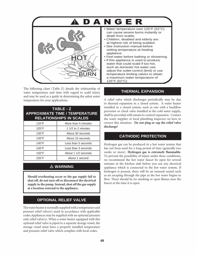
49
• Water temperature over 125°F (52°C) can cause severe burns instantly or death from scalds.• Children, disabled and elderly are at highest risk of being scalded.• See instruction manual before setting temperature at heating appliance.• Feel water before bathing or showering.• If this appliance is used to produce water that could scald if too hot, such as domestic hot water use, adjust the outlet control (limit) or use temperature limiting valves to obtain a maximum water temperature of 125°F (52°C).
TABLE - ZAPPROXIMATE TIME / TEMPERATURE
RELATIONSHIPS IN SCALDS120°F More than 5 minutes
125°F 1 1/2 to 2 minutes
130°F About 30 seconds
135°F About 10 seconds
140°F Less than 5 seconds
145°F Less than 3 seconds
150°F About 1 1/2 seconds
155°F About 1 second
The following chart (Table Z) details the relationship of water temperature and time with regard to scald injury and may be used as a guide in determining the safest water temperature for your applications.
Should overheating occur or the gas supply fail to shut off, do not turn off or disconnect the electrical supply to the pump. Instead, shut off the gas supply at a location external to the appliance.
� WARNING
OPTIONAL RELIEF VALVE
The water heater is normally supplied with a temperature and pressure relief valve(s) sized in accordance with applicable codes.Appliances may be supplied with an optional pressure only relief valve(s). When a water heater equipped with this optional relief valve is piped to a separate storage vessel, the storage vessel must have a properly installed temperature and pressure relief valve which complies with local codes.
THERMAL EXPANSION
A relief valve which discharges periodically may be due to thermal expansion in a closed system. A water heater installed in a closed system, such as one with a backflow preventer or check valve installed in the cold water supply, shall be provided with means to control expansion. Contact the water supplier or local plumbing inspector on how to correct this situation. Do not plug or cap the relief valve discharge!
CATHODIC PROTECTION
Hydrogen gas can be produced in a hot water system that has not been used for a long period of time (generally two weeks or more). Hydrogen gas is extremely flammable. To prevent the possibility of injury under these conditions, we recommend the hot water faucet be open for several minutes at the kitchen sink before you use any electrical appliance which is connected to the hot water system. If hydrogen is present, there will be an unusual sound such as air escaping through the pipe as the hot water begins to flow. There should be no smoking or open flames near the faucet at the time it is open.

50
THERMOSTAT
W1R1
TRANSFORMER
IGNITER
IGN MOD P5 AIR BLOWERCOMBUSTION
A
OFF ON
POWER SWITCH
L1(HOT)
L2
TO 120 VAC POWER SUPPLY
24 VAC
120 VAC
LWCO
LWCO6 2
LBL20019 R
EV
A*
IF EQ
UIP
PE
D
PUMPDELAY
24VDCPUMPDELAY
MRHL
R2 W2
HFGV
X B
GASVALVE
C
NO
NC
C
NO
NC
TDR
ALARMCONTACTS
LOUVERCONTACTS
RELAY(ALARM)
LIMITSWITCH
FLOWSWITCH LOW
AIR
*
*
*
**
*
*
*
IGNITIONMODULE
ALARM BELL
PUMP
IGN MOD P6
CN 7
CN 8
CN
2-2
CN 1-3
CN
2-1
CN 1-4
P 3-1P 3-7
P 3-8P 3-2
P 3-3
P 3-6 P 3-5
*
OP
TION
AL EQ
UIP
ME
NT W
IRIN
G
WA
TER
HE
ATE
R
LADDER DIAGRAM - WATER HEATER150,000 - 300,000 BTU/HR
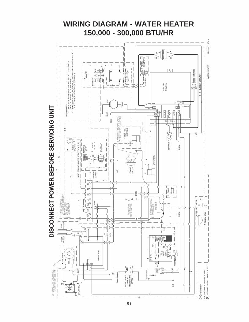
51
TRAN
SFO
RM
ER
ON
-OFF
SW
ITC
H
LOW
AIR
NONCC
PU
MP
*
R1
W1
AX
SW
ITC
H
TER
MIN
AL
BO
AR
D
IGN
ITE
R
BLO
WE
R
BC
LIM
IT
GA
S V
ALV
E
IGN
ITIO
NM
OD
ULE
BK
BK
/WB
K/W
W GR
W
GR
BL
OR
/R
BL
OR
Y
R/W
R/O
R
R/B
K
T
R
Y
Y
GR
W
YB
L
BK
W
BR W
GY
GY
R/B
K
GA
S V
ALV
EH
IGH
FIR
E
R/B
K
LBL2
0017
RE
V A
R2
W2
Y GYGY
BU
RN
ER
GRO
UN
D
GRWBR
R/W
BL
WBK
*
OR
Y
W
2 1 C
NO
C* FL
OW
SWIT
CH
PU
MP
DE
LAY
/FR
EE
ZEP
RO
TEC
TIO
N24
VD
C
OP
T. A
MR
HL
OP
T. F
MR
HL
*
R/B
K
R/W
BL/
W
R/B
K
OR
OR
BR
IF E
QU
IPP
ED
WIR
ING
NO
TES:
1.
RE
MO
VE
JU
MPE
R B
ETW
EE
N “W
1” A
ND
“R1”
TO
CO
NN
EC
T
REM
OTE
OPE
RAT
OR
OR
MO
D-U
-PAK
. 2.
W
IRE
ALL
PRO
VIN
G S
WIT
CH
ES,
FLO
W S
WIT
CH
ES,
AN
D C
ON
TRO
LS T
O“X
” & “B
” IN
SER
IES
TO S
CR
EW
TER
MIN
ALS.
NO
TE: R
EM
OVE
JU
MP
ER
BE
TWE
EN
"X" &
"B".
OP
TIO
NAL
AM
RH
L R
EQU
IRE
SM
AX
STO
P S
ET
@ 2
40°F
INLE
TS
EN
SO
R BK B
K
TAN
KS
EN
SO
R
8 7-C
6-N
O5-
NC
1
2-C
3-N
O4-
NC
*
1 4
3 62 5
IF N
OT
EQ
UIP
PE
D
WIT
H L
WC
O C
ON
NE
CT
TO "R
1". E
LSE
CO
NN
EC
T TO
LWC
O "C
OM
".
BL
BL
OR
Y
YB
L
BL
BL
BR
BR
ALA
RM
BE
LL
ALA
RM
*24
V R
ELAY
TIM
E D
ELAY
REL
AY
BL B
L
BL
BL
SP
LIC
E 5
Y
YT
Y
*
IF N
OT
EQ
UIP
PE
D
WIT
H L
WC
O
WIR
ES
TIE
DO
FF &
CA
PP
ED
IF N
O H
IGH
FIR
E G
AS
VA
LVE
WIR
ES
TIE
D O
FF &
CA
PP
ED
THER
MO
STA
T
*ALA
RM
CO
NTA
CTS
DIS
CO
NN
ECT
POW
ER B
EFO
RE
SERV
ICIN
G U
NIT
BL
CN
O
12
3
Y
OR
R
R
24V
REL
AY
TER
MIN
AL
STR
IP
*LOU
VE
RC
ON
TAC
TS
WAT
ER
HE
ATE
R
T
P
OP
TIO
NAL
EQ
UIP
ME
NT
WIR
ING
BL/
W
2 1
(+)(+
)
US
E E
LEC
TRIC
AL C
ON
NE
CTI
ON
1&
2
2 1
RES
ET
GN
D
RE
SET
P
J41
23J2
J1
O.C
.
3 2 1
6 45
J3
T
G
24VA
C
LWC
OB
L/B
K
OR
24V
YBL
PR
PR
OR
OR
OR
BU
TTO
NTE
ST
PROBE
TT
RES
ET
PR
PR
WIRING DIAGRAM - WATER HEATER150,000 - 300,000 BTU/HR

52
W1R1
TRANSFORMER
IGNITER
AIR BLOWERCOMBUSTION
A
OFF ON
POWER SWITCH
L1(HOT)
L2
TO 120 VAC POWER SUPPLY
24 VAC
120 VAC
LWCO
LWCO6 2
LBL20018 R
EV
A*
IF EQ
UIP
PE
D
PUMPDELAY
24VDCPUMPDELAY
MRHL
R2 W2
HFGV
C
NO
NC
C
NO
NC
TDR
ALARMCONTACTS
LOUVERCONTACTS
RELAY(ALARM)
*
*
**
*
*
*ALARM BELL
* 24VPUMPRELAY
24VACPUMPRELAY
PUMP*
IGN MOD P5
IGN MOD P6
THERMOSTAT
CN 7
CN 8
CN
2-2
CN 1-3
CN
2-1
CN 1-4
CN 1-2CN 1-1A
X B
GASVALVE
LIMITSWITCH
FLOWSWITCH LOW
AIR
*
IGNITIONMODULE
P 3-1P 3-7
P 3-8P 3-2
P 3-3
P 3-6 P 3-5
OP
TION
AL E
QU
IPM
EN
T WIR
ING
BO
ILER
LADDER DIAGRAM - BOILER150,000 - 300,000 BTU/HR
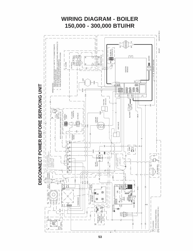
53
TRAN
SFO
RM
ER
ON
-OFF
SW
ITC
H
LOW
AIR
NONCC
PU
MP
*
R1
W1
AX
SW
ITC
H
IGN
ITE
R
BLO
WE
R
BC
LIM
IT
GA
S V
ALV
E
IGN
ITIO
NM
OD
ULE
24 V
AC
BK
BK
/WB
K/W
W GR
W
GR
BL
OR
/R
BL
OR
Y
R/W
R/O
R
R/B
K
T
R
Y
Y
GR
W
YBL BK
W
BR W
GY
GY
REL
AY
R/B
K
GA
S V
ALV
EH
IGH
FIR
E
R/B
K
LBL2
0016
RE
V A
R2
W2
Y GYGY
BU
RN
ER
GR
OU
ND
GRWBR
R/W
BL
WBK
YB
R
BK
*
T
OP
TIO
NAL
EQ
UIP
ME
NT
WIR
ING
Y
W
2 1 C
NO
C* FL
OW
SW
ITC
H
PU
MP
DEL
AY/
FRE
EZE
PR
OTE
CTI
ON
24 V
DC
OP
T. A
MR
HL
OP
T. F
MR
HL
**
*
R/B
K
YR
/WB
L/W
R/B
K
OR
OR
BL
PK
IF E
QU
IPP
ED
WIR
ING
NO
TES
:1.
R
EM
OV
E JU
MPE
R B
ETW
EEN
“W1”
AN
D “R
1” T
O C
ON
NE
CT
REM
OTE
O
PER
ATO
R O
R M
OD
-U-P
AK
. 2.
W
IRE
ALL
PR
OV
ING
SW
ITC
HES
, FLO
W S
WIT
CH
ES, A
ND
CO
NTR
OLS
TO
“X
” & “B
” IN
SER
IES
TO S
CR
EW
TER
MIN
ALS
. 3.
PU
MP
DEL
AY O
PE
RAT
ION
IS O
PTI
ON
AL W
ITH
KIT
3058
. N
OTE
: RE
MO
VE
JU
MPE
R B
ETW
EE
N "X
" & "B
".
SP
LIC
E 5
IF N
OT
EQ
UIP
PE
D
WIT
H L
WC
O
8 7-C
6-N
O5-
NC
1
2-C
3-N
O4-
NC
*
1 4
3 62 5
IF N
OT
EQ
UIP
PE
D
WIT
H L
WC
O C
ON
NE
CT
TO "R
1". E
LSE
CO
NN
EC
T TO
LWC
O "C
OM
".
BLBL
OR
YBL
BL
BL
BR
BR
Y
ALA
RM
BEL
L
ALA
RM
* 24V
RE
LAY
TIM
E D
ELA
Y R
ELA
Y
THE
RM
OS
TAT
*A
LAR
MC
ON
TAC
TS
DIS
CO
NN
ECT
POW
ER B
EFO
RE
SERV
ICIN
G U
NIT
OU
TDO
OR
AIR
RES
ET
*S
EN
SO
R
BL
CN
O
12
3
CN O
TER
MIN
AL
BO
AR
D
OR
Y
OR
R
R
24V
RE
LAY
TER
MIN
AL
STR
IP
Y
*LOU
VE
RC
ON
TAC
TS
BL
INLE
TS
EN
SO
R
BK
BK
SYS
TEM
SE
NS
OR
BL
BO
ILE
R
T
P
*
BL/
W
PK
2 1
US
E E
LEC
TRIC
AL C
ON
NE
CTI
ON
1&
2
(+)
(+)
2 1
RE
SE
T
GN
DP
J41
23J2
J1
O.C
.
3 2 1
6 45
J3
BU
TTO
NTE
ST PROBE
TT
T
G
2424
VA
C
LWC
O24
VYBL
OR
PU
OR
OR
PR
PR
BL/
BK
RE
SE
TP
RP
R
WIRING DIAGRAM - BOILER150,000 - 300,000 BTU/HR

54
STEP 1
WITH 120 VAC POWER TOAPPLIANCE, TURN ON POWERSWITCH, SWITCH LIGHTS UP?
120 VAC POWER TO UNIT? NO CHECK 120 VAC POWER SUPPLY.NO
YES
CHECK WIRING TO SWITCH?
YES
CHECK 120 VAC THRU SWITCH?
NO CHECK WIRING CONNECTIONS.
NO REPLACE SWITCH.
YES
STEP 2 IGNITION CONTROL MODULE? NO NO CHECK WIRING CONNECTIONS.120 VAC MODULE?
YES
REPLACE MODULE.
YES
STEP 3
SET THERMOSTAT BELOW WATER TEMPERATURE.
YES
STEP 4 SET THERMOSTAT TO CALL
FOR HEAT.
YES
STEP 5
COMBUSTION AIR BLOWER(CAB) STARTS? NO AIR PROVING SWITCH OPEN? NO REPLACE SWITCH.
YESCHECK FOR 120 VACAT CAB? NO CHECK WIRING CONNECTIONS.
YES
REPLACE CAB.
YES
STEP 6 NO AIR SHUTTER ADJUSTMENT
CORRECT? SEE INSTRUCTIONS.AIR PROVING SWITCH CLOSES? NO ADJUST AIR SHUTTER TO
PROPER SET POINTS; CHECKFOR AIR LEAKS FROM BURNER COMPARTMENT / PRESSURE HOSE.YES
IGNITION MODULE PURGE"LED" LIGHTS UP? NO
"LED" BURNED OUT BUT CONTROLFUNCTIONS. REPLACE AT A CONVENIENT TIME.
YESREPLACE SWITCH.
YES
STEP 7
IGNITION MODULE IGNITER "LED"LIGHTS UP & PURGE "LED" TURNS OFF?
YES
NO"LED" BURNED OUT BUT CONTROLFUNCTIONS. REPLACE AT A CONVENIENT TIME.
STEP 8
NOTE: THIS CHART IS FORCONTINUOUS PUMPS ONLY.SEE INSTALLATION INSTRUCTIONSFOR INTERMITTENT PUMP ANDPUMP DELAY OPTIONS FOR PUMP OPERATION.
NOTE: MUST OPEN WITHIN45 SEC. AFTER CALL FORHEAT AND CLOSE WITHIN5 MIN. AFTER CAB STARTSOR MODULE LOCKS OUT.
TROUBLESHOOTING CHART

55
STEP 9 NO CHECK WIRING CONNECTIONS.NO
YES
REPLACE IGNITER/SENSOR.
YES
STEP 10 NO
YES
GAS VALVE OPEN?
YES
STEP 11
IGNITER "LED" TURNS OFF& VALVE "LED" STAYS ON?
STEP 12
YES
IGNITER / SENSOR WARMS UPAND GLOWS RED. 120 VAC AT IGNITER/SENSOR?
NO
REPLACE MODULE.
IGNITION MODULE VALVE"LED" LIGHTS UP?
"LED" BURNED OUT BUT CONTROLFUNCTIONS. REPLACE AT A CONVENIENT TIME.
NO
24 VAC TO GAS VALVE? NO CHECK WIRING CONNECTIONS.
NO REPLACE GAS VALVE.
YES
NO CHECK WIRING CONNECTIONS.
YES
NO CHECK MOUNTING.
YES
NO
YES
MAIN BURNER RUNS UNTILCALL FOR HEAT ENDS ANDVALVE "LED" TURNS OFF?
YES
MANIFOLD PRESSURE CORRECT? NOSET MANIFOLD PRESSURE.SEE INSTRUCTIONS.
YES
REPLACE IGNITER.
CONTINUITY OF CHASSISGROUND CONNECTIONS? NO TIGHTEN OR REPLACE GROUND.
YES
IGNITER/SENSOR MOUNTED PROPERLY? NO CORRECT MOUNTING.
YES
REPLACE IGNITER.
CHASSIS GROUND & WIRING CONNECTIONS TO IGNITER?
IGNITER/SENSOR MOUNT PROPERLY?
GAS SUPPLY PRESSURE TO GAS VALVE CORRECT?
SET THERMOSTAT ABOVE WATER TEMPERATURE?
YES
STEP 13
THERMOSTAT OPENS?
YESNO
REPLACE THERMOSTAT.
GAS VALVE CLOSES?
YES
NO
STEP 14
STEP 15
GAS VALVE CLOSES WHEN ONE LEAD IS REMOVED? REPLACE GAS VALVE.
CAB STOPS AFTER 30 SEC. POST PURGE?STEP 16
YES
SYSTEM OK?STEP 17 NO
REPEAT PROCEDURE UNTILSYSTEM OPERATES NORMALLY.
SET GAS SUPPLY PRESSURE.SEE INSTRUCTIONS.
NO
TROUBLESHOOTING CHART (CONTINUED)

Revision 6 (EB-EW-i&s-06) reflects changes made to the O.A. section.
Revision 7 - (EB-EW-I&s-07) reflects changes made to LBLs on Pages 50-53.
Revision 8 - (ECO #C02870) reflects changes made to the scald section, pages 47 - 49 and the addition of a mixing valve to the piping diagram (FIG. 51, pg. 47).
Revision 9 - (ECO #C03126) reflects changes made to Table Q (Air Shutter Adjustment Opening) on page 37.
Revision 10 (ECO C12077) reflects the update of ignition timing information on page 35 and heat exchanger text on page 48.
Revision 11 (ECO #C12972) reflects the addition of the CSA Low Lead Content logo.
EB-EW-I-S-1106/13