eaug - issue 2 compressed - stardot.org.ukstardot.org.uk/mirrors/ · 15.6 the a to d converter 229...
TRANSCRIPT


The Advanced
User Guide
for the Acorn Electron Adrian C. Dickens BA, Churchill College, Cambridge University Mark A. Holmes BA, Fitzwilliam College, Cambridge University
Published by Adder Publishing, Cambridge

2
The “Acorn Electron Advanced User Guide” is published by Adder Publishing for Acornsoft Limited. Acornsoft Limited, Betjeman House, 104 Hills Road, Cambridge, CR2 1LQ, England. Telephone (0223) 316039 ISBN 0907876 17 X Copyright © 1984 Adder Publishing Adder Publishing, PO Box 148, Cambridge, CB1 2EQ ISBN 0 947929 03 7 First published September 1984 Second edition June 2008 The Authors would like to thank Nigel Dickens, Tim Dobson, Steve Furber, Tim Gleeson, David Johnson-Davies, Dr John Horton, Zahid Najam, Mark Plumbley, John Thackeray, Ken Vail, Geoff Vincent, Adrian Warner, Leycester Whewell, Albert Williams and everyone else who helped in the production of this book. All rights reserved. This book is copyright. No part of this book may be copied or stored by any means whatsoever whether mechanical, photographic or electronic, except for private or study use as defined in the Copyright Act. All enquiries should be addressed to the publishers. While every precaution has been taken in the preparation of this book, the publisher assumes no responsibility for errors or omissions. Neither is any liability assumed for damages resulting from the use of information contained herein. The Authors gratefully acknowledge Acorn Computers Limited for their kind permission to reproduce the complete Electron circuit diagram. The Authors would like to point out that Acorn Computers reserve the right to make improvements in the specification of its products. Therefore the circuit diagram and other contents of this book may not be in complete agreement with the product supplied. Please note that within this text the terms Tube, Econet and Electron are registered tradenames of Acorn Computers Limited. All references in this book to the BBC Microcomputer refer to the computer produced for the British Broadcasting Corporation by Acorn Computers Limited. This book was prepared using the Acornsoft VIEW wordprocessor on the BBC Microcomputer and then computer typeset by Parker Typesetting Service, Leicester. Printed in Great Britain by The Burlington Press Ltd. Foxton, Cambridge. Book production by Adder Publishing.

3
Contents Introduction 1 The Acorn design philosophy 7 Operating system routines and vectors 2 Operating system calls 9
2.1 OSWRCH Write character routine 10 2.2 Non-vectored OSWRCH 10 2.3 OSRDCH Read character routine 11 2.4 Non-vectored OSRDCH 11 2.5 OSNEWL Write a newline routine 12 2.6 OSASCI Write character routine 12 2.7 GSINIT General string input initialize 13 2.8 GSREAD Read character from string 13 2.9 OSRDRM Read byte from paged ROM 14 2.10 OSEVEN Generate an event 15 2.11 OSCLI Pass string to the CLI 15
3 OSBYTE calls 16 4 OSWORD calls 87 5 Filing system calls 94
5.1 OSFILE Read/write entire file 95 5.2 OSARGS Read/write file attributes 98 5.3 OSBGET Get a single byte 100 5.4 OSBPUT Write a single byte 101 5.5 OSGBPB Read/write a group of bytes 102 5.6 OSFIND Open or close file 105 5.7 OSFSC Misc filing system control 106
6 Operating system vectors 110
6.1 The User vector 113 6.2 The BRK vector 116 6.3 Interrupt vectors, IRQ1V & IRQ2V 119

4
6.4 The event vector, EVNTV 119 6.5 User print vector, UPTV 121 6.6 Econet vector, NETV 123 6.7 VDU extension vector, VDUV 124 6.8 Keyboard vector, KEYV 125 6.9 Buffer maintenance vectors 126 6.10 Unused vectors 134 6.11 The default vector table 134
7 Interrupts 135 7.1 Introduction 135 7.2 Interrupts on the Electron 138 7.3 Using NMIs 138 7.4 Using IRQs 138 7.5 Intercepting interrupts 139
Paged ROM firmware 8 Paged ROM formats 143
8.1 Paged ROM header format 144 8.2 Language entry 144 8.3 Service entry 145 8.4 ROM type byte 145 8.5 Copyright offset pointer 146 8.6 Binary version number 146 8.7 Title string 146 8.8 Version string 147 8.9 Copyright string 147 8.10 Tube relocation address 148
9 Language ROMs 148
9.1 Language initialization 148 9.2 Firm keys 149 9.3 Language ROM compatibility 150
10 Service ROMs 152
10.1 Paged ROM service calls 152 10.2 Service ROM example 162 10.3 Extended vectors 171
11 *ROM filing system ROMs 172
11.1 Converting files to *ROM format 173 11.2 The header code 173 11.3 Service call &D 174

5
11.4 Service call &E 175 11.5 *ROM data format 176 11.6 Example 178
Memory usage 12 Memory allocation and usage 183 Hardware 13 An introduction to hardware 201 14 Inside the Electron 204
14.1 The ULA and its registers 204 14.2 The keyboard 216
15 Outside the Electron 217
15.1 Introduction 217 15.2 The expansion connector 217 15.3 Designing circuits 222 15.4 Sideways ROMs 225 15.5 The 1MHz bus 227 15.6 The A to D converter 229 15.7 Disabling the Plus 1 229
Appendices A VDU code summary 230 B PLOT routine functions 232 C Screen MODE layouts 234 D OS calls and vectors 241 E Plus 1 ROM connector 243 F Complete circuit diagram 250 G Hardware expansions 252 Bibliography 256 Glossary 257 Index 262

6
Introduction The Advanced User Guide for the Electron has been designed to be an invaluable reference guide for users of the Electron computer. The original Electron User Guide provides a description of BASIC on the Electron and reaches the point at which programming in Assembly Language is introduced, along with a very brief introduction to the available system calls. The Advanced User Guide takes over at this point by providing a thorough, well indexed and cross referenced description of all the available facilities and how to use them. This will allow the serious programmer to make the most of his/her machine, whilst keeping within the Acorn Guidelines to ensure compatibility with other machines in the Acorn BBC Micro series. It is inevitable that a machine like the Electron should be partially overpowered by its big brother the BBC Micro. However, many of the facilities which are provided on the larger machine can also be added on to an Electron. A whole new series of operating system calls have been provided to take account of this, and are described within these pages. What may not at first sight be so apparent is that in many ways the Electron has more expansion potential than a BBC Micro! This is because all of the 6502 bus lines are available to expansion modules via the expansion connector. A full description of this connector, including interfacing details for paged ROMs and other devices have therefore been included. The authors have tried to provide a book which will be found by the side of all enthusiastic Electron programmers. All material is in an easily accessible referenced format. Where appropriate, examples are presented and discussed. In particular, there is a large section concerned with the use of paged ROMs. It is intended that this will help programmers to build up the necessary skills for producing their own exciting software in ROMs. All of the information contained in this book has been checked on an Electron fitted with Electron OS 1.00 and BASIC 2. Where appropriate, an Electron Plus 1 expansion module was also used.

7
1 The Acorn Design Philosophy A glance through the back pages of any microcomputer magazine will reveal a large number of machines ‘For Sale’. This is a reflection of the speed at which the industry moves; the all-new whizz-bang machine can become yesterday’s micro in as little as a year. The manufacturer has to tread a careful path; on the one hand he is committed to improving his products, but on the other he must not render his existing range obsolete. The Acorn design philosophy has been to produce a system right from the start which would allow for growth in both the software and hardware. All users should be aware of this if they wish their own software and hardware to be compatible with the complete range of available systems, from a humble Electron right up to a machine with Econet, second processor, hard disks etc. Ensuring compatibility is not hard, it simply requires a little self-discipline in your approach. The rules as such are simple. If your software needs to access anything outside its own domain (that is the memory and other resources it has been provided with) then use the officially supported operating system routines. The second is to make no assumptions about the environment your program will run under. This includes the amount of memory available, the processor and any other software / hardware components which might be there. Run-time enquiries have been built into the system to allow you to discover these facilities. Programs which run in RAM, say a simple Basic program, may discover that there is not enough memory available for them. A test for this should be made at the start of the program, since they should not be allowed to crash and should never use any memory outside their allocation. Programs placed in ROM should not make assumptions about their eventual run-time environment either. They may find themselves copied over the Tube and

8
running in RAM on another processor! One of the most common situations on the BBC microcomputer where incompatibility arises, is where software is designed for use on non-Econet machines and then used on such machines. This ultimately denies the software producer a sale and denies the Econet machine owner use of a particular program. This is a situation which can be avoided by intelligent software design and reasonable product testing. The Electron contains fewer pitfalls in this respect, but where software is destined for a wider distribution, the programmer should think about different machine configurations and potential problems.

9
2 Operating System Calls The list below contains all the Acorn supported operating system routines and their vectors which exist in the Electron OS 1.00. See the User Guide for a general description of these calls.
2.1 OSWRCH Write character routine Call address &FFEE Indirected through &20E This routine outputs the character in the accumulator to the currently selected output stream(s). On exit: A, X and Y are preserved. C, N, V and Z are undefined. The interrupt status is preserved (though interrupts may be enabled during a call).
2.2 Non-vectored OSWRCH Call address &FFCB This call is normally made by OSWRCH. This call has no vector and so cannot be intercepted. Its use is not recommended for this reason.

10
2.3 OSRDCH Read character routine Call address &FFE0 Indirected through &210 This routine reads a character from the currently selected input stream and returns it in the accumulator. On exit: C=0 indicates that a valid character has been read. C= 1 indicates that a character has not been read due to an error. If an error should occur acknowledgement of the error condition should be made using OSBYTE &7E. X and Y are preserved. N, V and Z are undefined. The interrupt status is preserved (though interrupts may be enabled during a call).
2.4 Non-vectored OSRDCH Call address &FFC8 This call is normally made by OSRDCH, it is not available for interception and its use is not recommended by Acorn.

11
2.5 OSNEWL Write a newline routine Call address &FFE7 Not indirected This routine writes a line feed (&A/10) and a carriage return (&D/13) to the current output stream(s) using OSWRCH. On exit: A=&0D (13) X and Y are preserved. C, N, V and Z are undefined. Interrupt status is preserved (though it may be enabled during a call).
2.6 OSASCI Write character routine, OSNEWL called if A=&0D (13). Call address &FFE3 Not indirected This is a write character routine performing the same action as OSWRCH but which outputs a line feed and a carriage return in response to a carriage return character. On exit: A, X and Y are preserved. C, N, V and Z are undefined. Interrupt status is preserved (though interrupts may be enabled during a call).
12
2.7 GSINIT General string input initialise routine. Call address &FFC2 The original intention was that this routine together with GSREAD would provide a standard string input facility for the use of filing system paged ROMs. It is now felt that this routine is unsuitable for that purpose and accordingly its use is not recommended. This routine initialises a string for input prior to reading using GSREAD. Entry parameters: String address stored in &F2 and &F3 plus offset in Y C=0, if first space, CR or second ” terminates input C=1, if first space does not terminate input On exit:
Y contains the offset of the first non-blank character from the address contained in &F2 and &F3. A contains the first non-blank character of string Z flag is set if the string is a null string
2.8 GSREAD Read character from string input routine. Call address &FFC5 This routine is used to read characters from an input string after a GSINIT call. Control codes and non-ASCII values may be introduced into the input string by using an escape character, ‘|‘. The escape character followed by a letter gives a character value equal to the ASCII value minus 64 (&40). The escape character followed by a ‘1’ character gives a value of 128 plus the value of the next character in the string. An escape character followed by itself gives the escape character.

13
Entry parameters: &F2, &F3 and Y set by GSINIT C=0 String terminated by first space, carriage return or second quotation mark. C=1 String terminated by carriage return or second quotation mark.
On exit:
A contains the character read from the string. Y contains the index for the next character to be read. C=1 if the end of string is reached. X is preserved.
2.9 OSRDRM Read byte from paged ROM routine. Call address &FFB9 This call returns a byte read from a paged ROM. Entry parameters:
ROM number stored in Y. Address stored in &F6 and &F7.
On exit:
A contains the value of the byte read. This routine was included for the implementation of ROM filing system software in paged ROM and is not recommended for general use.
14
2.10 OSEVEN Generate an event routine. Call address &FFBF The user event may be generated using this routine. Software replacing OS routines should generate the appropriate events by making this call. Entry parameter: The event number should be placed in Y. On exit: C=0 if and only if the event was enabled.
2.11 OSCLI Pass string to the CLI. Call address &FFF7 Indirected through &208 This routine is implemented on the BBC micro, the Electron and the Tube operating system. This call provides the machine code user with a convenient method of performing any of the * commands that the system provides from Basic. The command required is placed in a string as normal text and this call is made. If the string passed to the CLI is not terminated by a carriage return within 255 bytes this routine has undefined effects. The following commands are recognised: * String escape character rest of command ignored *. treated as a *CAT command */ treated as a *RUN command *BASIC select BASIC as current language *CAT issue catalogue request to filing system *CODE passed to user vector (see chapter 6) *EXEC select text file as input stream

15
*FX issue OSBYTE call (no registers returned) *HELP issue paged ROM service call 9, see chapter 10 *KEY take rest of line as text for soft key *LINE passed to user vector (see chapter 6) *LOAD issue load request to filing system *MOTOR open/close cassette motor relay *OPT issue option request to filing system *ROM select *ROM filing system *RUN issue load and execute request to filing system *SAVE issue save request to filing system *SPOOL include text file in output stream *TAPE select tape filing system *TV ignored by the Electron These commands may be abbreviated by taking the first few letters and terminating with a ‘.’ character. Parameters may be passed in the text following the command. Other unrecognised commands are first offered to paged ROMs (see section 10.1) and are then offered to the currently selected filing system via the filing system control vector (see chapter 5). Entry parameters: X and Y contain the address of a line of text (X=low-byte, Y=high-byte) terminated by a CR character. On exit: A, X, Y, C, N, V and Z are undefined. Interrupt status is preserved but interrupts may be enabled during a call.

16
3 OSBYTE calls OSBYTE calls are a powerful and flexible way of invoking many of the available operating system facilities. OSBYTE calls are specified by the contents of the accumulator (A register) in the 6502. This means that up to 256 different calls can be made. The command line interpreter (see section 2.11) performs OSBYTE calls in response to *FX commands. This enables the user to make OSBYTE calls from the keyboard or within BASIC programs. It should be noted however that no results are returned by a *FX call and so it is inappropriate to use certain OSBYTEs in this way. OSBYTE Miscellaneous OS functions specified by the
contents of the accumulator. Call address &FFF4 Indirected through &20A On entry: A selects an OSBYTE routine. X contains an OSBYTE parameter. Y contains an OSBYTE parameter. All calls are made to the OSBYTE subroutine at address &FFF4. This is then indirected through the vector at &20A (which means that user programs can intercept the OSBYTE calls before they get to the operating system if so desired). The selected function is determined by the accumulator contents. Two parameters can be passed to and from OSBYTE routines by putting the values to be passed in the X and Y registers respectively.

17
Example Using OSBYTE 4 to disable cursor editing. From BASIC this would be typed as: *FX 4,1 From assembly language it could be performed as: LDA #4 \Load accumulator with 4 LDX #1 \Select cursor disabled option JSR &FFF4 \Make OSBYTE call If an OSBYTE is not recognised by the Electron, it will be offered to any fitted paged ROMs (see chapters 8 to 11). The OSBYTE will then usually be claimed by the relevant expansion module’s ROM. When OSBYTE is called directly, if none of the paged ROMs claim it then the call returns with the overflow flag set. If the OSBYTE itself was initiated by a *FX command then the *FX handler will generate the ‘Bad command’ error. When OSBYTE calls are used in a second processor only a limited amount of information is returned. For low numbered OSBYTE calls (0 to 127) only the X register is returned and for high numbered OSBYTE calls only the X and Y registers, and the carry flag are returned. All the OSBYTE calls recognised by the operating system are described on the following pages. The description for each call includes details of the entry parameters required and the state of the registers on exit. All OSBYTE calls may be made using the *FX command, but it is not always appropriate to do so (i.e. those calls returning values in the X and Y registers). Where it is appropriate to use a *FX command this has been indicated. Preceding the full OSBYTE descriptions is a complete summary of the OSBYTE calls in a list.

18
OSBYTE/*FX Call Summary dec. hex. function 0 0 Print operating system version. 1 1 Set the User flag. 2 2 Select input stream. 3 3 Select output stream. 4 4 Enable/disable cursor editing. 5 5 Select printer destination. 6 6 Set character ignored by printer. 7 7 Set RS423 baud rate for receiving data. 8 8 Set RS423 baud rate for data transmission. 9 9 Set flashing colour mark state duration. 10 A Set flashing colour space state duration. 11 B Set keyboard auto-repeat delay interval. 12 C Set keyboard auto-repeat rate. 13 D Disable events. 14 E Enable events. 15 F Flush selected buffer class. 16 10 Select ADC channels to be sampled. 17 11 Force an ADC conversion. 18 12 Reset soft keys. 19 13 Wait for vertical sync. 20 14 Explode soft character RAM allocation. 21 15 Flush specific buffer. 22 16 Increment paged ROM polling semaphore 23 17 Decrement paged ROM polling semaphore 24 18 Change sound system. OSBYTE/*FX calls 25 (&19) to 114 (&72) are not used by OS 1.00. 115 73 Blank/restore palette. 116 74 Reset internal sound system. 117 75 Read VDU status. 118 76 Read keyboard status. 119 77 Close any SPOOL or EXEC files. 120 78 Write to two-key-roll-over locations.

19
121 79 Perform keyboard scan. 122 7A Perform keyboard scan from 16 (&10). 123 7B Inform OS, printer driver going dormant. 124 7C Clear ESCAPE condition. 125 7D Set ESCAPE condition. 126 7E Acknowledge detection of ESCAPE condition. 127 7F Check for EOF on an open file. 128 80 Read ADC channel or get buffer status. 129 81 Read key with time limit or key depression. 130 82 Read machine high order address. 131 83 Read top of OS RAM address (OSHWM). 132 84 Read bottom of display RAM address (HIMEM). 133 85 Read bottom of display address for a given MODE. 134 86 Read text cursor position (POS and VPOS). 135 87 Read character at cursor position. 136 88 Perform *CODE. 137 89 Perform *MOTOR. 138 8A Insert value into buffer. 139 8B Perform *OPT. 140 8C Perform *TAPE. 141 8D Perform *ROM. 142 8E Enter language ROM. 143 8F Issue paged ROM service request. 144 90 Perform *TV (not implemented). 145 91 Get character from buffer. 146 92 Read from FRED, 1 MHz bus. 147 93 Write to FRED, 1 MHz bus. 148 94 Read from JIM, 1 MHz bus. 149 95 Write to JIM, 1 MHz bus. 150 96 Read from SHEILA, 1 MHz bus. 151 97 Write to SHEILA, 1 MHz bus. 152 98 Examine buffer status. 153 99 Insert character into input buffer. 154 9A Reset video flash cycle. 155 9B Reserved. 156 9C Read/write 6850 control register and copy. 157 9D ‘Fast Tube BPUT’ 158 9E Read from speech processor. 159 9F Write to speech processor. 160 A0 Read VDU variable value.

20
OSBYTE/*FX calls 161 (&A1) to 165 (&A5) are not used by OS 1.00 and are reserved for future expansion. 166 A6 Read start address of OS variables (low byte). 167 A7 Read start address of OS variables (high byte). 168 A8 Read address of ROM pointer table (low byte). 169 A9 Read address of ROM pointer table (high byte). 170 AA Read address of ROM information table (low byte). 171 AB Read address of ROM information table (high byte). 172 AC Read address of key translation table (low byte). 173 AD Read address of key translation table (high byte). 174 AE Read start address of OS VDU variables (low byte). 175 AF Read start address of OS VDU variables (high byte). 176 B0 Read/write filing system timeout counter. 177 B1 Read/write input source. 178 B2 Enable/disable keyboard scanning 179 B3 Read/write primary OSHWM. 180 B4 Read/write current OSHWM. 181 B5 Read/write RS423 mode. 182 B6 Read character definition explosion state. 183 B7 Read/write cassette/ROM filing system switch. 184 B8 Undefined. 185 B9 Read/write timer paged ROM service call semaphore. 186 BA Read/write ROM number active at last BRK (error). 187 BB Read/write number of ROM socket containing BASIC. 188 BC Read current ADC channel. 189 BD Read/write maximum ADC channel number. 190 BE Read ADC conversion type. 191 BF Read/write RS423 use flag. 192 C0 Read RS423 control flag. 193 C1 Read/write flash counter. 194 C2 Read/write space period count. 195 C3 Read/write mark period count. 196 C4 Read/write keyboard auto-repeat delay. 197 C5 Read/write keyboard auto-repeat period. 198 C6 Read/write *EXEC file handle. 199 C7 Read/write *SPOOL file handle. 200 C8 Read/write ESCAPE, BREAK effect. 201 C9 Read/write Econet keyboard disable. 202 CA Read/write keyboard status byte.

21
203 CB Read/write the ULA interrupt mask. 204 CC Read/write Firm key pointer. 205 CD Read/write length of current firm key string. 206 CE Read/write Econet OS call interception status. 207 CF Read/write Econet OSRDCH interception status. 208 D0 Read/write Econet OSWRCH interception status. 209 D1 Read/write speech suppression status. 210 D2 Read/write sound suppression status. 211 D3 Read/write BELL channel. 212 D4 Read/write BELL (CTRL G) sound information. 213 D5 Read/write BELL frequency. 214 D6 Read/write BELL duration. 215 D7 Read/write startup message and !BOOT options. 216 D8 Read/write length of soft key string. 217 D9 Read/write number of lines printed since last page. 218 DA Read/write number of items in VDU queue. 219 DB Read/write External sound flag. 220 DC Read/write ESCAPE character value. 221 DD Read/write i/p buffer code interpretation status. 222 DE Read/write i/p buffer code interpretation status. 223 DF Read/write i/p buffer code interpretation status. 224 E0 Read/write i/p buffer code interpretation status. 225 E1 Read/write function key status. 226 E2 Read/write firm key status. 227 E3 Read/write firm key status. 228 E4 Read/write CTRL+SHIFT+function key status. 229 E5 Read/write ESCAPE key status. 230 E6 Read/write flags determining ESCAPE effects. 231 E7 Reserved. 232 E8 Sound semaphore. 233 E9 Soft key pointer. 234 EA Read flag indicating Tube presence. 235 EB Read flag indicating speech processor presence. 236 EC Read/write write character destination status. 237 ED Read/write cursor editing status. 238 EE Read/write OS workspace bytes. 239 EF Read/write OS workspace bytes. 240 F0 Read country code. 241 F1 Read/write user flag location. 242 F2 Read RAM copy of &FE07. 243 F3 Read timer switch state. 244 F4 Read/write soft key consistency flag.

22
245 F5 Read/write printer destination flag. 246 F6 Read/write character ignored by printer. 247 F7 Read/write first byte of BREAK intercept code. 248 F8 Read/write second byte of BREAK intercept code. 249 F9 Read/write third byte of BREAK intercept code. 250 FA Read/write OS workspace locations. 251 FB Read/write OS workspace locations. 252 FC Read/write current language ROM number. 253 FD Read/write last BREAK type. 254 FE Read/write available RAM. 255 FF Read/write start up options.
OSBYTE &00 (0) Identify OS version See OSBYTE &81 for more information regarding OS identification. Entry parameters: X=0 Execute BRK with a message giving the OS version X<>0 RTS with OS version returned in X On exit: X=0, OS 1.00 or Electron OS 1.00 X=1, OS 1.20 or American OS A and Y are preserved C is undefined

23
OSBYTE &01 (1) Set the user flag Entry parameters: The user flag is replaced by X On exit: X=old value This call uses OSBYTE with A=&F1 (241). This OSBYTE call is left free for user applications and is not used by the operating system. The user flag has a default value is 0.
OSBYTE &02 (2) Select input stream In the Electron any call with X<>0 will result in an unknown OSBYTE service call being made to the paged ROMs unless a previous such call was recognised and thus changed the input source. Entry parameters: X determines input device(s) *FX 2,0 X=0 keyboard selected, RS423 disabled *FX 2,1 X=1 RS423 selected and enabled *FX 2,2 X=2 keyboard selected, RS423 enabled Default: *FX 2,0 On exit: X=0 if previous input was from the keyboard X= 1 if previous input was from RS423 A is preserved Y and C are undefined

24
OSBYTE &03 (3) Select output stream If RS423 output is selected in the Electron, paged ROM service calls are issued. In the absence of a suitable response this output is sunk (thrown away). The same applies to printer output if selected. Bit 3 should not be used to enable the printer as this may conflict with the Econet protocol of claiming the printer. Entry parameters: X determines output device(s)
Bit o/p selected if bit is set 0 Enables RS423 driver 1 Disables VDU driver 2 Disables printer driver 3 Enables printer, independent of CTRL B or C 4 Disables spooled output 5 Not used 6 Disables printer driver unless the character is preceded
by a VDU 1 (or equivalent) 7 Not used
*FX 3,0 selects the default output options which are :
RS423 disabled VDU enabled Printer enabled (if selected by VDU 2) Spooled output enabled (if selected by *SPOOL)
On exit:
A is preserved X contains the old output stream status Y and C are undefined

25
OSBYTE &04 (4) Enable/disable cursor editing Entry parameters: X determines the status of the editing keys *FX 4,0 X=0 Enable cursor editing (default setting) *FX 4,1 X=1 Disable cursor editing and make them return normal ASCII values like the other keys.
The cursor control keys will return the following codes: COPY &87 (135)
LEFT &88 (136) RIGHT &89 (137) DOWN &8A (138) UP &8B (139) *FX 4,2 X=2 Disable cursor editing and make the keys act as soft keys with the following soft key associations :
COPY 11 LEFT 12 RIGHT 13 DOWN 14 UP 15
On exit: A is preserved X contains the previous status of the editing keys Y and C are undefined

26
OSBYTE &05 (5) Select printer destination Entry parameters: X determines print destination
*FX 5,0 X=0 Printer sink (printer output ignored) *FX 5,1 X=1 Parallel output *FX 5,2 X=2 RS423 output (sink if RS423 enabled) *FX 5,3 X=3 User printer routine (see section 6.5) *FX 5,4 X=4 Net printer (see section 6.5) *FX 5,5 to *FX5,255 User printer routine (see section 6.5) Default setting: *FX 5,0 On Exit:
A is preserved X contains the previous *FX 5 setting Y and C are undefined Interrupts are enabled by this call This call is not reset to default by a soft break
OSBYTE &06 (6) Set character ignored by printer Entry parameters:
X contains the character value to be ignored *FX 6,10 X=10 This prevents LINE FEED characters being
sent to the printer, unless preceded by VDU 1 (this is the default setting)
On exit:
A is preserved X contains the previous *FX 6 setting Y and C are undefined
This is not reset by soft BREAK.
27
OSBYTE &07 (7) Set RS423 baud rate for receiving data This routine is not implemented on the unexpanded Electron. If this OSBYTE is used on the electron an unknown OSBYTE service call is made to the paged ROMs. This call is reserved for future expansion.
OSBYTE &08 (8) Set RS423 baud rate for data transmission This routine is not implemented on the unexpanded Electron. If this OSBYTE is used on the Electron an unknown OSBYTE service call is made to the paged ROMs. This call is reserved for future expansion.
OSBYTE &09 (9) Set duration of the mark state of flashing colours (Duration of first named colour) Entry parameters:
X determines duration *FX 9,0 X=0 Sets mark duration to infinity Forces mark state if space is set to 0 *FX 9,n X=n Sets mark duration to n VSYNC periods (n=25 is the default setting) On exit:
A is preserved X contains the old mark duration Y and C are undefined

28
OSBYTE &0A (10) Set duration of the space state of flashing colours (Duration of second named colour) Entry parameters:
X determines duration *FX 10,0 X=0 Sets space duration to infinity. Forces space
state if mark is set to 0 *FX 10,n X=n Sets space duration to n VSYNC periods
(n=25 is the default setting) On exit:
A is preserved X contains the old space duration Y and C are undefined
OSBYTE &0B (11) Set keyboard auto-repeat delay Entry parameters:
X determines delay before repeating starts *FX 11,0 X=0 Disables auto-repeat facility *FX 11,n X=n Sets delay ton centiseconds (n=50 is the
default setting) After call,
A is preserved X contains the old delay setting Y and C are undefined

29
OSBYTE &0C (12) Set keyboard auto-repeat period Entry parameters:
X determines auto-repeat periodic interval *FX 12,0 X=0 Resets delay and repeat to default values *FX 12,n X=n Sets repeat interval to n centiseconds (n=8 is
the default value) On exit:
A is preserved X contains the old *FX 12 setting Y and C are undefined
OSBYTE &0D (13) Disable events Entry parameters : X contains the event code, Y=0 *FX 13,0 X=0 Disable output buffer empty event *FX 13,1 X=1 Disable input buffer full event *FX 13,2 X=2 Disable character entering buffer event *FX 13,3 X=3 Disable ADC conversion complete event *FX 13,4 X=4 Disable start of vertical sync event *FX 13,5 X=5 Disable interval timer crossing 0 event *FX 13,6 X=6 Disable ESCAPE pressed event *FX 13,7 X=7 Disable RS423 RX error event *FX 13,8 X=8 Disable network error event *FX 13,9 X=9 Disable user event See section 6.4 for information on event handling. On exit:
A is preserved X contains the old enable state (0=disabled) Y and C are undefined

30
OSBYTE &0E (14) Enable events Entry parameters: X contains the event code, Y=0 *FX 14,0 X=0 Enable output buffer empty event *FX 14,1 X=1 Enable input buffer full event *FX 14,2 X=2 Enable character entering buffer event *FX 14,3 X=3 Enable ADC conversion complete event *FX 14,4 X=4 Enable start of vertical sync event *FX 14,5 X=S Enable interval timer crossing 0 event *FX 14,6 X=6 Enable ESCAPE pressed event *FX 14,7 X=7 Enable RS423 RX error event *FX 14,8 X=8 Enable network error event *FX 14,9 X=9 Enable user event After call,
A is preserved X contains the old enable state (>0= enabled) C is undefined
See section 6.4 for information on event handling.
OSBYTE &0F (15) Flush selected buffer class Entry parameters:
X value selects class of buffer
X=0 All buffers flushed X=1 Input buffer flushed only
See OSBYTE call &16/*FX 21 On exit,
Buffer contents are discarded A is preserved X, Y and C are undefined

31
OSBYTE &10 (16) Select ADC channels which are to be sampled This routine is not implemented on the unexpanded Electron but is passed on to paged ROMs as an unknown OSBYTE paged ROM service call. On an Electron fitted with the Plus 1 expansion, this call selects the number of analogue to digital conversion channels, where X is a number in the range 0 (no channels) to 4 (all four channels).
OSBYTE &11 (17) Force an ADC conversion This routine is not implemented on the unexpanded Electron but is passed on to paged ROMs as an unknown OSBYTE paged ROM service call. On an Electron fitted with the Plus 1 expansion, this call forces analogue to digital conversion to restart for channels 1 to X.
OSBYTE &12 (18) Reset soft keys This call clears the soft key buffer so the character strings are no longer available. No parameters On exit:
A and Y are preserved X and C are undefined

32
OSBYTE &13 (19) Wait for vertical sync No parameters This call forces the machine to wait until the start of the next frame of the display. This occurs 50 times per second on the UK Electron. Its main use is to help produce flicker free animation on the screen. The flickering effect is often due to changes being made on the screen halfway through a screen refresh. Using this OSBYTE call graphics manipulation can be made to coincide with the flyback between screen refreshes. N.B. User trapping of IRQ1 may stop this call from working. On exit:
A is preserved X, Y and C are undefined
OSBYTE &14 (20) Explode soft character RAM allocation Entry parameters: X value explodes/implodes memory allocation In the default state 32 characters may be user defined using the VDU 23 statement from BASIC (or the OSWRCH call in machine code). These characters use memory from &C00 to &CFF. Printing ASCII codes in the range 128 (&80) to 159 (&9F) will cause these user defined characters to be printed up (these characters will also be printed out for characters in the range &A0-&BF, &C0-&DF, &E0-&FF), In this state the character definitions are said to be imploded. If the character definitions are exploded then ASCII characters 128 (&80) to 159 (&9F) can be defined as before using VDU 23 and memory at &C00. Exploding the character set definitions enables the user to uniquely define characters 32 (&20) to 255

33
(&FF) in steps of 32 extra characters at a time. The operating system must allocate memory for this which it does using memory starting at the ‘operating system high-water mark’ (OSHWM). This is the value to which the BASIC variable PAGE is usually set and so if a totally exploded character set is to be used in BASIC then PAGE must be reset to OSHWM+&600 (i.e. PAGE = PAGE + &600). ASCII characters 32 (&20) to 128 (&7F) are defined by memory within the operating system ROM when the character definitions are imploded. See OSBYTE &83 (131) for details about reading OSHWM from machine code. The memory allocation for ASCII codes in the expanded state is as follows: ASCII code Memory allocation *FX 20,0 X=0 &80-&8F &C00 to &CFF (imploded) *FX 20,1 X=1 &A0-&BF OSHWM to OSHWM+&FF (+above) *FX 20,2 X=2 &C0-&DF OSHWM+&100 to OSHWM+&1FF (+above) *FX 20,3 X=3 &E0-&FF OSHWM+&200 to OSHWM+&2FF (+above) *FX 20,4 X=4 &20-&3F OSHWM+&300 to OSHWM+&3FF (+above) *FX 20,5 X=5 &40-&5F OSHWM+&400 to OSHWM+&4FF (+above) *FX 20,6 X=6 &60-&7F OSHWM+&500 to OSHWM+&5FF (+above) The explosion state can be determined using OSBYTE &B6. Before the OSHWM is changed during a font explosion a service call is made to the paged ROMs warning them of the impending change.

34
On exit: A is preserved X contains the new OSHWM (high byte) Y and C are undefined
OSBYTE &15 (21) Flush specific buffer While the unexpanded Electron only has a single sound channel the operating system has been designed to enable the implementation of an external sound system. Each time any of the sound buffers are flushed a paged ROM service call is issued with A=&17. In the unexpanded Electron there is a single effective buffer which may be addressed as any of the four channels. Thus flushing any of the four buffers will extinguish any sound being produced at that time. See section 10.1 for more information regarding the Electron sound paged ROM service calls. Entry parameters:
X determines the buffer to be cleared
*FX 21,0 X=0 Keyboard buffer emptied *FX 21,1 X=1 RS423 input buffer emptied *FX 21,2 X=2 RS423 output buffer emptied *FX 21,3 X=3 Printer buffer emptied *FX 21,4 X=4 Sound channel 0 buffer emptied *FX 21,5 X=5 Sound channel 1 buffer emptied *FX 21,6 X=6 Sound channel 2 buffer emptied *FX 21,7 X=7 Sound channel 3 buffer emptied *FX 21,8 X=8 Speech buffer emptied See also OSBYTEs &0F (*FX15) and &80 (128). On exit:
A and X are preserved Y and C are undefined

35
OSBYTE &16 (22) Increment paged ROM polling semaphore This call increments the semaphore which when non-zero makes the operating system issue a paged ROM service call with A=&15 at centi-second intervals. See paged ROM service call &15, chapter 10. Entry parameters:
None On exit:
A and X are preserved Y and C are undefined
Semaphore is incremented once per call.
OSBYTE &17 (23) Decrement paged ROM polling semaphore This call decrements the semaphore which when non-zero makes the operating system issue a paged ROM service call with A=&15 at centi-second intervals. See paged ROM service call &15, chapter 10. Entry parameters:
None On exit:
A and X are preserved Y and C are undefined
Semaphore is decremented once per call.
36
OSBYTE &18 (24) Select external sound system This call is used to select a sound system which is implemented by an external hardware/software sound system. Entry parameters:
X contains an undefined parameter On exit:
A is preserved All other registers are undefined
OSBYTE &73 (115) Blank/restore palette This call is used to temporarily turn all colours in the palette black. It should be useful for NMI users who want to generate NMIs with a high resolution screen display. This will ensure that there is no snow seen on the screen. Entry parameters: X=0 Restores the palette
X<>0 Set palette to all black if in high res. mode On exit:
All registers undefined
OSBYTE &74 (116) Reset internal sound system This call can be used to reset the internal sound system. Entry parameters:
X contains an undefined parameter On exit:
All registers are undefined

37
OSBYTE &75 (117) Read VDU status No entry parameters On exit the X register contains the VDU status. Information is conveyed in the following bits : Bit 0 Printer output enabled by a VDU 2 Bit 1 Scrolling disabled e.g. during cursor editing Bit 2 Paged scrolling selected Bit 3 Software scrolling selected i.e. text window Bit 4 reserved Bit 5 Printing at graphics cursor enabled by VDU 5 Bit 6 Set when input and output cursors are separated (i.e.
cursor editing mode). Bit 7 Set if VDU is disabled by a VDU 21 On exit:
A and Y are preserved C is undefined
OSBYTE &76 (118) Reflect keyboard status in keyboard LEDs This routine is hardware dependent and is implemented differently on the BBC microcomputer and the Electron. This call should not be used on either machine.
38
OSBYTE &77 (119) Close any SPOOL or EXEC files This call closes any open files being used as *SPOOLed output or *EXECed input to be closed. This call is first offered to paged ROMs via a service call with A=&10. If the call is claimed then the operating system takes no further action. If the call is not claimed by a paged ROM the operating system closes any EXEC or SPOOL files itself. This call should be made by filing systems if they are deselected. On exit:
A is preserved X, Y and C are undefined
OSBYTE &78 (120) Write current keys pressed information This call should only be made by filing systems which have recognised a key pressed with BREAK and are initialising accordingly (see paged ROM service call with A=&03, section 10.1). This call should be used to write the old key pressed value to prevent its entry into the keyboard buffer. The operating system operates a two key roll-over for keyboard input (recognising a second key press even when the first key is still pressed). There are two zero page locations which contain the values of the two key-presses which may be recognised at any one time. If no keys are pressed, location &EC contains 0 and location &ED contains 0. If one key is pressed, location &EC contains the internal key number+128 (see table below for internal key numbers) and location &ED contains 0. If a second key is pressed while the original key is held down, location &EC contains the internal key number+128 of the most recent key pressed and location &ED contains the internal key number+128 of the first key pressed.

39
Internal Key Numbers
hex. dec. key hex. dec. key &00 0 SHIFT &40 64 CAPS LOCK &01 1 CTRL &41 65 A &02 2 bit0 &42 66 X &03 3 bit1 &43 67 F &04 4 bit2 &44 68 Y &05 5 bit3 &45 69 J &06 6 bit4 &46 70 K &07 7 bit5 &47 71 @ &08 8 bit6 &48 72 : &09 9 bit7 &49 73 RETURN &10 16 Q &50 80 SHIFT LOCK &11 17 3 &51 81 S &12 18 4 &52 82 C &13 19 5 &53 83 G &14 20 f4 &54 84 H &15 21 8 &55 85 N &16 22 f7 &56 86 L &17 23 - &57 87 ; &18 24 ^ &58 88 ] &19 25 left cursor &59 89 DELETE &20 32 f0 &60 96 TAB &21 33 W &61 97 Z &22 34 E &62 98 SPACE &23 35 T &63 99 V &24 36 7 &64 100 B &25 37 I &65 101 M &26 38 9 &66 102 , &27 39 0 &67 103 . &28 40 _ &68 104 / &29 41 down cursor &69 105 COPY &30 48 1 &70 112 ESCAPE &31 49 2 &71 113 f1 &32 50 D &72 114 f2 &33 51 R &73 115 f3 &34 52 6 &74 116 f5 &35 53 U &75 117 f6 &36 54 O &76 118 f8 &37 55 P &77 119 f9 &38 56 [ &78 120 \ &39 57 up cursor &79 121 right cursor
40
Bits 0 to 7 refer to the start up option byte. See OSBYTE &FF for further information about this byte. To convert these internal key numbers to the INKEY numbers they should be EOR (Exclusive ORed) with &FF (255). Entry parameters :
X and Y contain values to be written Value in X is stored as the old key information. Value in Y is stored in the new key information. See also OSBYTE calls with A=&AC and A=&AD. On exit:
A, X and Y are preserved C is undefined
OSBYTE &79 (121) Keyboard scan The keyboard is scanned in ascending numerical order. This call returns information about the first pressed key encountered during the scan. Other keys may also be pressed and a further call or calls will be needed to complete the entire keyboard scan. Entry parameters:
X determines the key to be detected and also determines the range of keys to be scanned.
Key numbers refer to internal key numbers in the table above (see OSBYTE &78).

41
To scan a particular key: X=key number EOR &80 on exit X<0 if the key is pressed
To scan the matrix starting from a particular key number:
X=key number On exit X=key number of any key pressed or &FF if no key pressed On exit:
A is preserved X contains key value (see above) Y and C are undefined
OSBYTE &7A (122) Keyboard scan from 16 decimal No entry parameters Internal key number (see table above) of the key pressed is returned in X. This call is directly equivalent to an OSBYTE call with A=&79 and X=16. On exit:
A is preserved X contains key number or zero if none pressed Y and C are undefined

42
OSBYTE &7B (123) Inform operating system of printer driver going dormant Entry parameters:
X should contain the value 3 (printer buffer id) This OSBYTE call should be made by user printer drivers when they go dormant. The operating system will need to wake up the printer driver if more characters are placed in the printer buffer (see section 6.5). On exit:
A and X are preserved Y is preserved C is undefined
OSBYTE &7C (124) Clear ESCAPE condition No entry parameters This call clears any ESCAPE condition without any further action. See OSBYTE &7E also. On exit:
A, X and Y are preserved C is undefined

43
OSBYTE &7D (125) Set Escape condition No entry parameters This call partially simulates the ESCAPE key being pressed. The Tube is informed (if active). An ESCAPE event is not generated. On exit:
A, X and Y are preserved C is undefined
OSBYTE &7E (126) Clear ESCAPE condition with side effects No entry parameters This call attempts to clear the ESCAPE condition. All active buffers will be flushed, any open EXEC files closed, the VDU paging counter will be reset and the VDU queue will be reset. See OSBYTE &E6 (230) also. On exit:
X=&FF if the ESCAPE condition cleared X=0 if no ESCAPE condition found
A is preserved Y and C are undefined

44
OSBYTE &7F (127) Check for end-of-file on an opened file Entry parameters:
X contains file handle On exit:
X<>0 If end-of-file has been reached X=0 If end-of-file has not been reached
A and Y are preserved (Y not passed across Tube) C is undefined
OSBYTE &80 (128) Read ADC channel (ADVAL) or get buffer status On the unexpanded Electron this call will generate an unknown OSBYTE paged ROM service call when passed a positive value in the X register. If this service call is not claimed then the values in page 2 of memory allocated to storing ADC information are returned. On an Electron fitted with a Plus 1 this call is implemented identically to on the BBC microcomputer. For positive values of X, the call operates the same as on a BBC microcomputer but information about buffers not present on an unexpanded Electron will be meaningless. Entry parameters:
X determines action and buffer or channel number If X=0 on entry: Y returns channel number (range 1 to 4) showing which channel was last used for ADC conversion, Note that OSBYTE calls with A=&10 (16) and A=&11 (17) set this value to 0. A value of 0 indicates that no conversion has been completed. Bits 0 and 1 of X indicate the status of the two ‘fire buttons’.

45
If X=1 to 4 on entry: X and Y contain the 16 bit value (X-low, Y-high) read from channel specified by X. This call may only be used from machine code (not from a *FX call). If X<0 and Y=&FF on entry: If X contains a negative value (in 2’s complement notation) then this call will return information about various buffers. X=255 (&FF) keyboard buffer X=254 (&FE) RS423 input buffer X=253 (&FD) RS423 output buffer X=252 (&FC) printer buffer X=251 (&FB) sound channel 0 X=250 (&FA) sound channel 1 X=249 (&F9) sound channel 2 X=248 (&F8) sound channel 3 X=249 (&F7) speech buffer For input buffers X contains the number of characters in the buffer and for output buffers the number of spaces remaining. On exit:
A is preserved C is undefined
OSBYTE &81 (129) Read key with time limit (INKEY) This call is functionally equivalent to the BASIC statement INKEY, It can be used to get a character from the keyboard within a time limit, scan the keyboard for a particular key press or return information about the OS type.
46
(a) Read key with time limit Entry parameters: X and Y specify time limit in centiseconds If a time limit of n centiseconds is required,
X=n AND &FF (LSB) Y=n DIV &100 (MSB)
Maximum time limit is &7FFF centiseconds (5.5 minutes approx.) On exit:
If key press detected, X=ASCII key value, Y=0 & C=0 If key press not detected by timeout then Y=&FF & C= 1 If Escape is pressed then Y=&1B (27) and C= 1
(b) Scan keyboard for key press Entry parameters:
X=negative INKEY value for key to be scanned Y=&FF
On exit:
X = Y = &FF, C= 1 if the key being scanned is pressed. X = Y = 0, C=0 if key is not pressed.
(c) Return information about OS type Entry parameters:
X=0 Y=&FF
On exit: X=0 BBC OS 0.1 X=1 Electron OS 1.00 X=&FF BBC OS 1.00 or OS 1.20 X=&FE US BBC OS 1.20

47
OSBYTE &82 (130) Read machine high order address No entry parameters This call yields the high order address required for the most significant 16 bits of the 32 bit addresses used for filing systems. The high order address is different in a second processor to that in an i/o processor. The Tube operating system intercepts this call to return the second processor high order address. On exit:
X and Y contain the address (X-high, Y-low)
A is preserved C is undefined
OSBYTE &83 (131) Return current OSHWM The OSHWM (operating system high water mark) represents the top of memory used by the operating system. This value is set after the paged ROMs have claimed workspace and any font explosion carried out. On a second processor this value represents the OSHWM on the i/o processor. The OSHWM indicates the start of user memory and so this call is made by BASIC to initialise the value of PAGE. No entry parameters On exit:
X and Y contain the OSHWM address (X= low-byte , Y = high-byte)
A is preserved C is undefined

48
OSBYTE &84 (132) Return HIMEM HIMEM is an address indicating the top of the available user RAM. This is usually the bottom of screen memory address. On a second processor this will be the bottom address of any code copied across from the I/O processor and executed. No entry parameters On exit:
X and Y contain the HIMEM address (X-low, Y-high)
A is preserved C is undefined
OSBYTE &85 (133) Read bottom of display RAM address for a specified mode This call may be used to investigate the consequences of an intended MODE change. This enables languages to determine whether the selection of a new MODE should be allowed. Entry parameters:
X determines mode number On exit:
X and Y contain the address (X-low byte, Y-high byte)
A is preserved C is undefined

49
OSBYTE &86 (134) Read text cursor position (POS and VPOS) When in cursor editing mode this call returns the position of the input cursor not the output cursor. No entry parameters On exit:
X contains horizontal position of the cursor (POS) Y contains vertical position of the cursor (VPOS)
A is preserved C is undefined
OSBYTE &87 (135) Read character at text cursor position and screen MODE No entry parameters On exit:
X contains character value (0 if character not recognised) Y contains graphics MODE number
A is preserved C is undefined
OSBYTE &88 (136) Execute code indirected via USERV (*CODE equivalent) This call JSRs to the address contained in the user vector (USERV &200). The X and Y registers are passed on to the user routine. See *CODE, section 6.1.

50
OSBYTE &89 (137) Switch cassette relay (*MOTOR equivalent) Entry parameters:
X=0 relay off X=1 relay on
The cassette filing system calls this routine with Y=0 for write operations and Y= 1 for read operations. This enables the implementation of a dual cassette system with additional hardware and software On exit:
A is preserved X, Y and C are undefined
OSBYTE &8A (138) Insert value into buffer Entry parameters:
X identifies the buffer (See OSBYTE &15) Y contains the to be value inserted into buffer
On exit:
C=0 if value successfully inserted C=1 if value not inserted e.g. if buffer full A is preserved
OSBYTE &8B (139) Select file options (*OPT equivalent) Entry parameters:
X contains file option number Y contains the option value required
On exit:
A is preserved C is undefined

51
OSBYTE &8C (140) Select tape filing system (*TAPE equivalent) No entry parameters On exit:
A is preserved C is undefined
OSBYTE &8D (141) Select ROM filing system (*ROM equivalent) No entry parameters On exit:
A is preserved X, Y and C are undefined
OSBYTE &8E (142) Enter language ROM Entry parameters:
X determines which paged ROM is entered The language ROM is entered via its entry point with A=1. Locations &FD and &FE in zero page are set to point to the copyright message in the ROM. There is no exit from this call.

52
OSBYTE &8F (143) Issue paged ROM service call See Service ROMs section 10.1. Entry parameters:
X=reason code Y=parameter passed with service call
On exit:
Y may contain return argument (if appropriate) X=0 if a paged ROM claimed the service call
A is preserved C is undefined
OSBYTE &90 (144) Alter display parameters (*TV equivalent) On the Electron this call is not implemented and returns with registers preserved.
OSBYTE &91 (145) Get character from buffer Entry parameters:
X contains buffer number (see OSBYTE &15) On exit:
Y contains the extracted character. If the buffer was empty then C= 1 otherwise C=0.
A is preserved

53
OSBYTEs &92 to &97 (146 to 151) Read or Write to mapped I/O Entry parameters:
X contains offset within page Y contains byte to be written (for write calls)
OSBYTE call Memory addressed Name read write &92 (146) &93 (147) &FC00 to &FCFF FRED &94 (148) &95 (149) &FD00 to &FDFF JIM &96 (150) &97 (151) &FE00 to &FEFF SHEILA Refer to the hardware section for details about these 1 MHz buses. On exit:
Read operations return with the value read in the Y register
A is preserved C is undefined
OSBYTE &98 (152) Examine Buffer status Entry parameters: X contains buffer number On exit: Y=character value read from buffer if buffer not empty
Y is preserved if buffer empty C=1 if buffer empty otherwise C=0
A and X are preserved

54
OSBYTE &99 (153) Insert character into input buffer, checking for ESCAPE Entry parameters:
X contains buffer number (0 or 1 only) Y contains the character value
X=0 keyboard buffer X=1 RS423 input
If the character is an ESCAPE character and ESCAPEs are not protected (using OSBYTE &C8/*FX 200 or OSBYTE &E5/*FX229) then an ESCAPE event is generated instead of the keyboard event. On exit:
A is preserved X, Y and C are undefined
OSBYTE &9A (154) Reset flash cycle This call resets the flash cycle to the beginning of the mark state (i.e. to the first named colour of the pair) by manipulating the ULA registers. There are no entry parameters. On exit:
All registers are undefined
OSBYTE &9B (155) Write to video ULA palette register and OS copy (BBC micro) On the Electron this call is ignored by immediately executing an RTS instruction.

55
OSBYTE &9C (156) Read/update 6850 control register and OS copy (BBC micro) On the Electron this call causes the operating system to issue an unknown OSBYTE paged ROM service call but makes no further actions.
OSBYTE &9D (157) Fast Tube BPUT The byte to be output is channeled through the standard BPUT routine. Entry parameters:
X = byte to be output Y = file handle
On exit:
A is preserved X, Y and C are undefined
OSBYTE &9E (158) Read from speech processor On the Electron this call causes the operating system to issue an unknown OSBYTE paged ROM service call but makes no further actions.
OSBYTE &9F (159) Write to speech processor On the Electron this call causes the operating system to issue an unknown OSBYTE paged ROM service call but makes no further actions.

56
OSBYTE &A0 (160) Read VDU variable value This call is implemented on the Electron but is officially undefined and may change in future issues of the OS. Entry parameters:
X contains the number of the variable to be read On exit:
X=low byte of variable A is preserved Y=high byte of variable C is undefined
OSBYTE &A3 (163) Disable/Enable printer and ADC This call is not implemented on the unexpanded Electron. On an Electron fitted with a Plus 1 interface, the call enables or disables input/output through the Plus 1: *FX163,128,0 - enables printer and ADCs *FX163,128,1 - disables printer and ADCs
OSBYTEs &A6 (166) and &A7 (167) Read start address of OS variables <NEW VALUE>=(<OLD VALUE> AND Y) EOR X The old value is returned in X. The contents of the next location are returned in Y. This call returns the start address of the memory used by the operating system to store its internal variables. On exit:
X=low byte A is preserved Y=high byte C is undefined

57
OSBYTEs &A8 (168) and &A9 (169) Read address of ROM pointer table This call is implemented on the BBC microcomputer and the Electron. When used across the Tube the address returned refers to the I/O processor’s memory. <NEW VALUE>=(<OLD VALUE> AND Y) EOR X The old value is returned in X. The contents of the next location are returned in Y. This table of extended vectors consists of 3 byte vectors in the form Location (2 bytes), ROM no. (1 byte). See Paged ROM section 10.3 for a complete description of extended vectors. On exit:
X=low byte Y=high byte A is preserved C is undefined
OSBYTEs &AA (170) and &AB (171) Read address of ROM information table <NEW VALUE>=(<OLD VALUE> AND Y) EOR X The old value is returned in X. The contents of the next location are returned in Y. This call returns the origin of a 16 byte table, containing one byte per paged ROM. This byte contains the ROM type byte contained in location &8006 of the ROM or contains 0 if a valid ROM is not present. On exit:
X=low byte A is preserved Y=high byte C is undefined

58
OSBYTEs &AC (172) and &AD (173) Read address of keyboard translation table This call is implemented on the BBC microcomputer and the Electron. However it should be noted that this call is hardware specific due to the different keyboard matrix layout on different machines. When used across the Tube the address returned refers to the I/O processor’s memory. Use of this call is not recommended. <NEW VALUE>=(<OLD VALUE> AND Y) EOR X The old value is returned in X. The contents of the next location are returned in Y. On exit:
X=low byte Y=high byte
OSBYTEs &AE (174) and &AF (175) Read VDU variables origin <NEW VALUE>=(<OLD VALUE> AND Y) EOR X The old value is returned in X. The contents of the next location are returned in Y. This call returns with the address of the table of internal VDU variables. On exit:
X=low byte Y=high byte

59
OSBYTE &B0 (176) Read/write CFS timeout counter <NEW VALUE>=(<OLD VALUE> AND Y) EOR X The old value is returned in X. The contents of the next location are returned in Y. This counter is decremented once every vertical sync pulse (50 times per second) which is also used for OSBYTE &13/*FX 19. The timeout counter is used to time interblock gaps and leader tones.
OSBYTE &B1 (177) Read input source flags <NEW VALUE>=(<OLD VALUE> AND Y) EOR X The old value is returned in X. The contents of the next location are returned in Y. This location should contain 0 for keyboard input and 1 for RS423 input (i.e. contains buffer no.) and is used for OSBYTE &2. OSBYTE &2 should be used to change the input source as writing the flag with this call does not enable the relevant interrupts.
OSBYTE &B2 (178) Enable/disable keyboard interrupt *FX178,0,0 Turns off keyboard interrupt *FX178,255,0 Turns on keyboard interrupt With keyboard interrupts disabled, the machine runs significantly faster, however the keyboard will no longer be scanned by the OS. To detect keypresses it is necessary to read the hardware directly (see Chapter 14).

60
OSBYTE &B3 (179) Read/write primary OSHWM (for imploded font) This call should not be used as it has been re-allocated on other products in the Acorn-BBC range. <NEW VALUE>=(<OLD VALUE> AND Y) EOR X The old value is returned in X. The contents of the next location are returned in Y. This location contains the OSHWM page value for an imploded font (even when character definition RAM explosion has been selected) but after paged ROM workspace allocation has been made. See OSBYTE &B4 and OSBYTE &14.
OSBYTE &B4 (180) Read OSHWM (similar to OSBYTE &83) <NEW VALUE>=(<OLD VALUE> AND Y) EOR X This call returns the page number of OSHWM in X. This location is updated by any character definition RAM explosion which may have been selected and returns with the high byte of the OSHWM address (the low byte always being 0). See OSBYTE &14.

61
OSBYTE &B5 (181) Read/write RS423 mode On the unexpanded Electron this call will have no effect unless a suitable hardware and software expansion has been performed to implement R5423. <NEW VALUE>=(<OLD VALUE> AND Y) EOR X The old value is returned in X. The contents of the next location are returned in Y. Flag=0 ESCAPEs are recognised soft keys are expanded
character entering input buffer event generated cursor editing performed
Flag= 1 All characters enter input buffer (default) character entering buffer event not generated
OSBYTE &B6 (182) Read character definition explosion state Use of this call is not recommended as this OSBYTE has been reallocated on other products in the Acorn BBC range. <NEW VALUE>=(<OLD VALUE> AND Y) EOR X The old value is returned in X. The contents of the next location are returned in Y. This location contains the state of font explosion as set by OSBYTE call with A=&14/*FX 20.

62
OSBYTE &B7 (183) Read cassette/ROM filing system flag <NEW VALUE>=(<OLD VALUE> AND Y) EOR X The old value is returned in X. The contents of the next location are returned in Y. This location contains 0 for *TAPE selection and 2 for *ROM selection. Other values are meaningless, and should not be used.
OSBYTE &B8 (184) This call is undefined on the Electron.
OSBYTE &B9 (185) Read/write timer paged ROM service call semaphore <NEW VALUE>=(<OLD VALUE> AND Y) EOR X The old value is returned in X. The contents of the next location are returned in Y. This location contains a semaphore. If the contents of this location are non-zero the operating system will generate a paged ROM service call with a reason code of &15. This semaphore should only be read using this call. See OSBYTEs &16 and &17 for information about setting semaphore and service ROMs chapter 10 for information about the paged ROM service call.

63
OSBYTE &BA (186)
Read ROM number active at last BRK (error) <NEW VALUE>=(<OLD VALUE> AND Y) EOR X The old value is returned in X. The contents of the next location are returned in Y. This location contains the ROM number of the paged ROM that was in use at the last BRK.
OSBYTE &BB (187) Read number of ROM socket containing BASIC <NEW VALUE>=(<OLD VALUE> AND Y) EOR X The old value is returned in X. The contents of the next location are returned in Y. BASIC is recognised by the fact that it is a language ROM which does not possess a service entry. This ROM is then selected by the *BASIC command. If no BASIC ROM is present then this location contains &FF.
OSBYTE &BC (188)
Read current ADC channel This call is not implemented in the unexpanded Electron. <NEW VALUE>=(<OLD VALUE> AND Y) EOR X The old value is returned in X. The contents of the next location are returned in Y. This location contains the number of the ADC channel currently being converted. This call should not be used to force ADC conversions, use OSBYTE &11/*FX 17.

64
OSBYTE &BD (189)
Read maximum ADC channel number. This call is not implemented in the unexpanded Electron. <NEW VALUE>=(<OLD VALUE> AND Y) EOR X The old value is returned in X. The contents of the next location are returned in Y. The maximum channel number to be used for ADC conversions in the range 0 to 4. Set by OSBYTE &16/*FX 10.
OSBYTE &BE (190)
Read ADC conversion type, 12 or 8 bits. This call is not implemented in the unexpanded Electron. <NEW VALUE>=(<OLD VALUE> AND Y) EOR X The old value is returned in X. The contents of the next location are returned in Y.
Set to &00, default (12 bit) Set to &08, 8 bit conversion Set to &0C,12 bit conversion
OSBYTE &BF (191)
Read/write RS423 use flag. This location is reserved for expansion software on the Electron. <NEW VALUE>=(<OLD VALUE> AND Y) EOR X The old value is returned in X. The contents of the next location are returned in Y.

65
OSBYTE &C0 (192) Read RS423 control flag This location is reserved for expansion software on the Electron. <NEW VALUE>=(<OLD VALUE> AND Y) EOR X The old value is returned in X. The contents of the next location are returned in Y.
OSBYTE &C1 (193) Read/write flash counter. <NEW VALUE>=(<OLD VALUE> AND Y) EOR X The old value is returned in X. The contents of the next location are returned in Y. This location contains the number of 1/50th sec. units until the next change of colour for flashing colours.
OSBYTE &C2 (194) Read/write space period count. <NEW VALUE>=(<OLD VALUE> AND Y) EOR X The old value is returned in X. The contents of the next location are returned in Y. Similar to OSBYTE &0A.
66
OSBYTE &C3 (195) Read/write mark period count. <NEW VALUE>=(<OLD VALUE> AND Y) EOR X The old value is returned in X. The contents of the next location are returned in Y. Similar to OSBYTE &09.
OSBYTE &C4 (196) Read/write keyboard auto-repeat delay. <NEW VALUE>=(<OLD VALUE> AND Y) EOR X The old value is returned in X. The contents of the next location are returned in Y. This call is used by OSBYTE &0B.
OSBYTE &C5 (197) Read/write keyboard auto-repeat period (rate). <NEW VALUE>=(<OLD VALUE> AND Y) EOR X The old value is returned in X. The contents of the next location are returned in Y. This call is used by OSBYTE &0C.

67
OSBYTE &C6 (198) Read *EXEC file handle. <NEW VALUE>=(<OLD VALUE> AND Y) EOR X The old value is returned in X. The contents of the next location are returned in Y. This call should be used only to read this location as writing to it may have undefined effects. This location contains zero if no file handle has been allocated by the operating system.
OSBYTE &C7 (199) Read *SPOOL file handle. <NEW VALUE>=(<OLD VALUE> AND Y) EOR X The old value is returned in X. The contents of the next location are returned in Y. This call should be used to read this location only. This location contains the file handle of the current SPOOL file or zero if not currently spooling.

68
OSBYTE &C8 (200) Read/write ESCAPE, BREAK effect <NEW VALUE>=(<OLD VALUE> AND Y) EOR X The old value is returned in X. The contents of the next location are returned in Y. bit 0 = 0 Normal ESCAPE action bit 0 = 1 ESCAPE disabled unless caused by OSBYTE
&7D/125 bits l to 7 = 0 Normal BREAK action bits l to 7 = 1 Memory cleared on BREAK e.g. A value 000000lx (binary) will cause memory to be cleared on BREAK.
OSBYTE &C9 (201) Read/write keyboard disable. This call should only be made by the Econet filing system. <NEW VALUE>=(<OLD VALUE> AND Y) EOR X The old value is returned in X. The contents of the next location are returned in Y. If this location contains 0 then the keyboard is scanned normally otherwise lock keyboard (all keys ignored except BREAK). This call is used by the *REMOTE Econet facility.

69
OSBYTE &CA (202) Read/write keyboard status byte. <NEW VALUE>=(<OLD VALUE> AND Y) EOR X The old value is returned in X. The contents of the next location are returned in Y. bit 4=0 if CAPS LOCK active bit 5=1 if Fn active bit 6=1 if SHIFT active bit 7=1 if CTRL active All bits except the CAPS LOCK bit will only change transiently and are subsequently unlikely to be of use. See also OSBYTE with A=&76 (118).
OSBYTE &CB (203) Read/write the ULA Interrupt Mask See chapter 7 for a description of the interrupt handling routine.
OSBYTE &CC (204) Read/write Firm Key Pointer <NEW VALUE>=(<OLD VALUE> AND Y) EOR X The old value is returned in X. The contents of the next location are returned in Y. The value contained in this location is a pointer into the currently expanding firm key. For more information about the firm keys see language ROMs section 9.2.

70
OSBYTE &CD (205) Read/write Length of current Firm key string. <NEW VALUE>=(<OLD VALUE> AND Y) EOR X The old value is returned in X. The contents of the next location are returned in Y. This location contains the length of the string currently being expanded from a Firm key. For more information about Firm keys see language ROMs section 9.2.
OSBYTE &CE (206) Read/write Econet OS call interception status. <NEW VALUE>=(<OLD VALUE> AND Y) EOR X The old value is returned in X. The contents of the next location are returned in Y. If bit 7 of this location is set then all OSBYTE and OS WORD calls (except those sent to paged ROMs) are indirected through the Econet vector (&224) to the Econet. Bits 0 to 6 are ignored.
OSBYTE &CF (207) Read/write Econet read character interception status. <NEW VALUE>=(<OLD VALUE> AND Y) EOR X The old value is returned in X. The contents of the next location are returned in Y. If bit 7 of this location is set then input is pulled from the Econet vector.

71
OSBYTE &D0 (208) Read/write Econet write character interception status. <NEW VALUE>=(<OLD VALUE> AND Y) EOR X The old value is returned in X. The contents of the next location are returned in Y. If bit 7 of this location is set then output is directed to the Econet. Output may go through the normal write character on return from the Econet code.
OSBYTE &D1 (209) Read/write speech suppression status. This location is not used in the unexpanded Electron and is reserved for future expansion. <NEW VALUE>=(<OLD VALUE> AND Y) EOR X The old value is returned in X. The contents of the next location are returned in Y.
OSBYTE &D2 (210) Read/write sound suppression status. <NEW VALUE>=(<OLD VALUE> AND Y) EOR X Setting X to zero allows sound to be generated. Setting X nonzero will prevent any further sound being produced. The old value is returned in X. The contents of the next location are returned in Y.

72
OSBYTE &D3 (211) Read/write BELL (CTRL G) channel. <NEW VALUE>=(<OLD VALUE> AND Y) EOR X The old value is returned in X. The contents of the next location are returned in Y. This location contains the channel number to be used for the BELL sound. Default value is 3.
OSBYTE &D4 (212) Read/write BELL (CTRL G) SOUND information. <NEW VALUE>=(<OLD VALUE> AND Y) EOR X The old value is returned in X. The contents of the next location are returned in Y. This location contains a byte which determines either the amplitude or the ENVELOPE number to be used by the BELL sound. If an ENVELOPE is specified then the value should be set to (ENVELOPE no.-1)*8. Similarly an amplitude in the range 15 to 0 must be translated by subtracting 1 and multiplying by 8. The least significant three bits of this location contain the H and 5 parameters of the SOUND command (see User Guide). Note that the internal sound system on the Electron will not allow the amplitude of the sound to be varied. Default value 144 (&90) on the Electron.

73
OSBYTE &D5 (213) Read/write bell (CTRL G) frequency. <NEW VALUE>=(<OLD VALUE> AND Y) EOR X The old value is returned in X. The contents of the next location are returned in Y. This value contains the pitch parameter (as used by SOUND command third parameter) used for the BELL sound. Default value 101 (&65) on the Electron.
OSBYTE &D6 (214) Read/write bell (CTRL G) duration. <NEW VALUE>=(<OLD VALUE> AND Y) EOR X The old value is returned in X. The contents of the next location are returned in Y. This value contains the duration parameter (as for SOUND command) used for the BELL sound. Default value 6 on the Electron.
OSBYTE &D7 (215) Read/write start up message suppression and !BOOT option status. <NEW VALUE>=(<OLD VALUE> AND Y) EOR X The old value is returned in X. The contents of the next location are returned in Y.
74
bit 0 If clear then ignore OS startup message. If set then print up OS startup message as normal.
bit 7 If set then if an error occurs in a !BOOT file in *ROM, carry on but if an error is encountered from a disc !BOOT file because no language has been initialised the machine locks up.
If clear then the opposite will occur, i.e. locks up if there is an error in *ROM.
This can only be over-ridden by a paged ROM on initialisation or by intercepting BREAK, see OSBYTE calls &F7 to &F9.
OSBYTE &D8 (216)
Read/write length of soft key string. <NEW VALUE>=(<OLD VALUE> AND Y) EOR X The old value is returned in X. The contents of the next location are returned in Y. This location contains the number of characters yet to be read from the soft key buffer of the current soft key. To clear input buffer use *FX 15/OSBYTE &0F.
OSBYTE &D9 (217)
Read/write number of lines since last halt in page mode. <NEW VALUE>=(<OLD VALUE> AND Y) EOR X The old value is returned in X. The contents of the next location are returned in Y. This location contains the number of lines printed since the last page halt. This value is used by the operating system to decide whether to halt scrolling when paged mode has been selected. This location is set to zero during OSWORD call &00 to prevent a scrolling halt occurring during input.

75
OSBYTE &DA (218) Read/write number of items in the VDU queue. <NEW VALUE>=(<OLD VALUE> AND Y) EOR X The old value is returned in X. The contents of the next location are returned in Y. This contains the 2’s complement negative number of bytes still required for the execution of a VDU command. Writing 0 to this location can be a useful way of abandoning a VDU queue, otherwise writing to this location is not recommended.
OSBYTE &DB (219) Read/write External sound flag <NEW VALUE>=(<OLD VALUE> AND Y) EOR X The old value is returned in X. The contents of the next location are returned in Y. This location contains a flag indicating that an external sound system has been selected using OSBYTE &18.

76
OSBYTE &DC (220)
Read/write Escape character. <NEW VALUE>=(<OLD VALUE> AND Y) EOR X The old value is returned in X. The contents of the next location are returned in Y. This location contains the ASCII character (and key) which will generate an ESCAPE condition or event. e.g. *FX 220,32 will make the SPACE bar the ESCAPE key. Default value &1B (27).
OSBYTEs &DD (221) to &E0 (224) Read/write I/P buffer code interpretation status. <NEW VALUE>=(<OLD VALUE> AND Y) EOR X The old value is returned in X. The contents of the next location are returned in Y. These locations determine the effect of the character values &C0 (192) to &FF (255) when placed in the input buffer. See OSBYTEs &E1 (225) to &E4 (228) for details about the different effects which may be selected. Note that these values cannot be inserted into the input buffer from the keyboard. RS423 input or a user keyboard handling routine may place these values into the input buffer. OSBYTE &DD affects interpretation of values &C0 to &BF OSBYTE &DE affects interpretation of values &D0 to &CF OSBYTE &DF affects interpretation of values &E0 to &EF OSBYTE &E0 affects interpretation of values &F0 to &FF Default values &01, &D0, &E0 and &F0 (respectively)

77
OSBYTE &E1 (225) Read/write function key status (soft keys/codes/null). Changes the effect of typing the user-defined function keys as follows: *FX225,0 - ignores the function keys *FX225,1 - the function keys will generate the character
string defined by the user using *KEY *FX225,2-255 - the function keys will generate an ASCII code
based on the second parameter: f1 generates a code one more than the second parameter, f2 a code two more, etc
OSBYTE &E2 (226) Read/write firm key status (soft key or code). Changes the effect of typing function keys in the range A to P (input buffer characters &90 to &9F), as follows: *FX226,0 - ignores function keys in this range *FX226,1 - function keys in this range will generate the
BASIC keywords marked on their keycaps *FX226,2-255 - function keys in this range will generate an
ASCII code based on the second parameter FUNC A produces a code the same as the second parameter, FUNC B a code one higher, etc.
OSBYTE &E3 (227) Read/write firm key status (soft key or code). Changes the effect of typing the remaining function keys (Q to Z plus : ; , - . /) (Input buffer characters &A0 to &AF), according to the same logic as OSBYTE &E2.

78
OSBYTE &E4 (228) Read/write CTRL+SHIFT+F key Status (soft key or code). Input buffer characters &B0 to &BF. <NEW VALUE>=(<OLD VALUE> AND Y) EOR X The old value is returned in X. The contents of the next location are returned in Y. These locations determine the action taken by the OS when a function key is pressed. value 0 totally ignore key. value 1 expand as normal soft key. value 2 to &FF add n (base) to soft key number to provide
ASCII code. The default settings are: fn keys alone &01 expand using soft key strings fn keys+ SHIFT &01 expand using firm key strings fn keys+CTRL &01 expand using firm key strings fn keys+SHIFT+CTRL &00 key has no effect When the BREAK key is pressed a character of value &CA is entered into the input buffer. The effect of this character may be set independently of the other soft keys using OSBYTE &DD (221). One of the other effects of pressing the BREAK key is to reset this call, so the usefulness of this facility is limited.
OSBYTE &E5 (229) Read/write status of ESCAPE key (escape action or ASCII code). <NEW VALUE>=(<OLD VALUE> AND Y) EOR X The old value is returned in X. The contents of the next location are returned in Y. If this location contains 0 then the ESCAPE key has its normal action. Otherwise treat currently selected ESCAPE key as an ASCII code.
79
OSBYTE &E6 (230) Read/write flags determining ESCAPE effects. <NEW VALUE>=(<OLD VALUE> AND Y) EOR X The old value is returned in X. The contents of the next location are returned in Y. If this location contains 0 then when an ESCAPE is acknowledged (using OSBYTE &7E/*FX 126) then :
EXEC file is closed (if open) Purge all buffers (including input buffer) Reset paging counter (lines since last halt) Reset VDU queue Any current soft key expansion is cleared
If this location contains any value other than 0 then ESCAPE causes none of these.
OSBYTE &E7 (231) Read/write IRQ bit mask for the user 6522 (BBC micro) <NEW VALUE>=(<OLD VALUE> AND Y) EOR X The old value is returned in X. The contents of the next location are returned in Y. This location is reserved for future Acorn expansion on the Electron.
OSBYTE &E8 (232) Read/write sound semaphore <NEW VALUE>=(<OLD VALUE> AND Y) EOR X This location contains the sound semaphore.
80
OSBYTE &E9 (233) Read/write soft key pointer <NEW VALUE>=(<OLD VALUE> AND Y) EOR X This location contains the soft key pointer.
OSBYTE &EA (234) Read flag indicating Tube presence. <NEW VALUE>=(<OLD VALUE> AND Y) EOR X The old value is returned in X. The contents of the next location are returned in Y. This location contains 0 if a Tube system is not present and &FF if Tube chips and software are installed. No other values are meaningful or valid.
OSBYTE &EB (235) Read flag indicating speech processor presence. This location is used differently on the BBC micro and the Electron. <NEW VALUE>=(<OLD VALUE> AND Y) EOR X The old value is returned in X. The contents of the next location are returned in Y. This location is reserved for future Acorn expansion on the Electron.
81
OSBYTE &EC (236) Read/write write character destination status. <NEW VALUE>=(<OLD VALUE> AND Y) BOR X The old value is returned in X. The contents of the next location are returned in Y. This call is used by OSBYTE &3/*FX 3.
OSBYTE &ED (237) Read/write cursor editing status. <NEW VALUE>=(<OLD VALUE> AND Y) EOR X The old value is returned in X. The contents of the next location are returned in Y. This call is used by OSBYTE &4/*FX 4.
OSBYTEs &EE (238) and &EF (239) Read/write OS workspace bytes. These locations are reserved for future Acorn expansion on the Electron. <NEW VALUE>=(<OLD VALUE> AND Y) EOR X The old value is returned in X. The contents of the next location are returned in Y.

82
OSBYTE &F0 (240)
Read country code <NEW VALUE>=(<OLD VALUE> AND Y) EOR X The old value is returned in X. The contents of the next location are returned in Y. This location contains a value indicating the country for which this version of the operating system has been written. country code country
0 United Kingdom 1 United States
OSBYTE &F1 (241)
Read/write User flag location. <NEW VALUE>=(<OLD VALUE> AND Y) EOR X The old value is returned in X. The contents of the next location are returned in Y. This call is not used by the operating system and is unlikely to be used by later issues either. This location is reserved as a user flag for use with *FX 1. Default value 0.
OSBYTE &F2 (242)
Read RAM copy of location &FE07 <NEW VALUE>=(<OLD VALUE> AND Y) BOR X This location contains a RAM copy of the last value written to the ULA at address &FE07. The old value is returned in X. The contents of the next location are returned in Y.

83
OSBYTE &F3 (243) Read timer switch state. <NEW VALUE>=(<OLD VALUE> AND Y) EOR X The old value is returned in X. The contents of the next location are returned in Y. The OS maintains two internal clocks which are updated alternately, As the OS alternates between the two clocks it toggles this location between values of 5 and 10. These values represent offsets within the OS workspace where the clock values are stored. This OS workspace location should not be interfered with.
OSBYTE &F4 (244) Read/write soft key consistency flag. <NEW VALUE>=(<OLD VALUE> AND Y) EOR X The old value is returned in X. The contents of the next location are returned in Y. If this location contains 0 then the soft key buffer is in a consistent state. A value other than 0 indicates that the soft key buffer is in an inconsistent state (the operating system does this during soft key string entries and deletions). If the soft keys are in an inconsistent state during a soft break then the soft key buffer is cleared (otherwise it is preserved). OSBYTE &F5 (245)
Read/write printer destination flag. <NEW VALUE>=(<OLD VALUE> AND Y) EOR X The old value is returned in X. The contents of the next location are returned in Y. This call is used by OSBYTE &5/*FX 5. Using this call does not check for the printer previously selected being inactive or inform the user printer routine. See section 6.1.

84
OSBYTE &F6 (246)
Read/write character ignored by printer. <NEW VALUE>=(<OLD VALUE> AND Y) EOR X The old value is returned in X. The contents of the next location are returned in Y. This call is used by OSBYTE &6/*FX 6.
OSBYTEs &F7 (247), &F8 (248) and &F9 (249) Read/write BREAK intercept code. <NEW VALUE>=(<OLD VALUE> AND Y) EOR X The old value is returned in X. The contents of the next location are returned in Y. The contents of these locations must be a JMP instruction for BREAKs to be intercepted (the OS identifies the presence of an intercept by testing the first location contents equal to &4C - JMP). This code is entered twice during each break. On the first occasion C=0 and is performed before the reset message is printed or the Tube initialised. The second call is made with C=1 after the reset message has been printed and the Tube initialised. OSBYTEs &FA (250) and &FB (251)
Read/write OS workspace locations. These locations are reserved for future Acorn expansions on the Electron. <NEW VALUE>=(<OLD VALUE> AND Y) EOR X The old value is returned in X. The contents of the next location are returned in Y.

85
OSBYTE &FC (252)
Read/write current language ROM number. <NEW VALUE>=(<OLD VALUE> AND Y) EOR X The old value is returned in X. The contents of the next location are returned in Y. This location is set after use of OSBYTE &8E/*FX 126. This ROM is entered following a soft BREAK or a BRK (error).
OSBYTE &FD (253)
Read hard/soft BREAK. <NEW VALUE>=(<OLD VALUE> AND Y) EOR X The old value is returned in X. The contents of the next location are returned in Y This location contains a value indicating the type of the last BREAK performed.
value 0 - soft BREAK value 1 - power up reset value 2 - hard BREAK
OSBYTE &FE (254) Read/write available RAM (BBC micro) <NEW VALUE>=(<OLD VALUE> AND Y) EOR X The old value is returned in X. The contents of the next location are returned in Y. This location is reserved for future Acorn expansion. Default value 0 in the unexpanded Electron.
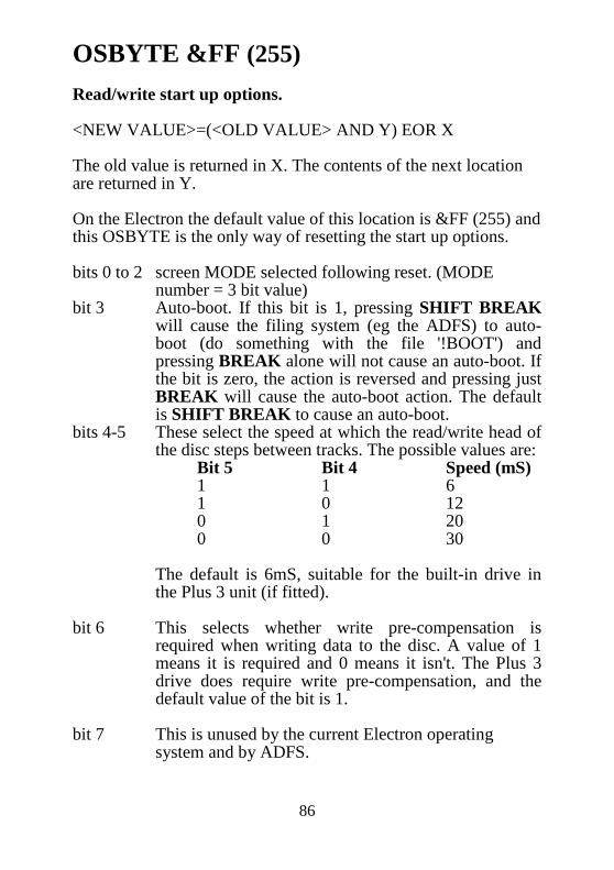
86
OSBYTE &FF (255) Read/write start up options. <NEW VALUE>=(<OLD VALUE> AND Y) EOR X The old value is returned in X. The contents of the next location are returned in Y. On the Electron the default value of this location is &FF (255) and this OSBYTE is the only way of resetting the start up options. bits 0 to 2 screen MODE selected following reset. (MODE
number = 3 bit value) bit 3 Auto-boot. If this bit is 1, pressing SHIFT BREAK
will cause the filing system (eg the ADFS) to auto-boot (do something with the file '!BOOT') and pressing BREAK alone will not cause an auto-boot. If the bit is zero, the action is reversed and pressing just BREAK will cause the auto-boot action. The default is SHIFT BREAK to cause an auto-boot.
bits 4-5 These select the speed at which the read/write head of the disc steps between tracks. The possible values are:
Bit 5 Bit 4 Speed (mS) 1 1 6 1 0 12 0 1 20 0 0 30 The default is 6mS, suitable for the built-in drive in
the Plus 3 unit (if fitted). bit 6 This selects whether write pre-compensation is
required when writing data to the disc. A value of 1 means it is required and 0 means it isn't. The Plus 3 drive does require write pre-compensation, and the default value of the bit is 1.
bit 7 This is unused by the current Electron operating
system and by ADFS.

87
4 OSWORD Calls The OSWORD routines are very similar in concept to the OSBYTE routines. The major difference arises in the way of passing parameters. Instead of being passed in the X and Y registers, they are placed in a parameter block, The address of this parameter block is sent to the routine in the X (for the low byte) and Y (for the high byte) registers. OSWORD OS call specified by contents of A taking
parameters in a parameter block. Call address &FFF1 Indirected through &20C On entry,
A selects an OSWORD routine. X contains low byte of the parameter block address. Y contains high byte of the parameter block address.
OSWORDs which are called with accumulator values in the range &E0 (224) to &FF (255) are passed to the USERV (&200). The routine indirected through the USERV is entered with the register contents unchanged from the original OSWORD call. Other unrecognised OSWORD calls are offered to the paged ROMs (see service ROMs section 10.1, reason code 8). OSWORD summary A=0 Read line from currently selected input into memory. A=1 Read system clock. A=2 Write system clock. A=3 Read interval timer. A=4 Write interval timer. A=5 Read byte of I/O processor memory. A=6 Write byte of I/O processor memory. A=7 Perform a SOUND command. A=8 Define an ENVELOPE.

88
A=9 Read pixel value. A=&A Read character definition. A=&B Read palette value for a given logical colour. A=&C Write palette value for a given logical colour. A=&D Read previous and current graphics cursor positions. OSWORD call with A=&0 Read line from input This routine takes a specified number of characters from the currently selected input stream. Input is terminated following a RETURN or an ESCAPE. DELETE (&7F/127) deletes the previous character and CTRL U (&15/21) deletes the entire line. If characters are presented after the maximum line length has been reached the characters are ignored and a BEL (ASCII 7) character is output. The parameter block XY+ 0 Buffer address for input LSB 1 MSB 2 Maximum line length 3 Minimum acceptable ASCII value 4 Maximum acceptable ASCII value Only characters greater or equal to XY+3 and less than or equal to XY+4 will be accepted. On exit:
C=0 if a carriage return terminated input. C=1 if an ESCAPE condition terminated input. Y contains line length, excluding carriage return if used.
OSWORD call with A=&1 Read system clock This routine may be used to read the system clock (used for the TIME function in BASIC). The five byte clock value is written to the address contained in the X and Y registers. This clock is incremented every hundredth of a second and is set to 0 by a hard BREAK.

89
OSWORD call with A=&2 Write System Clock This routine may be used to set the system clock to a five byte value contained in memory at the address contained in the X and Y registers. OSWORD call with A=&3 Read interval timer This routine may be used to read the interval timer (used for events, see section 6.4). The five byte clock value is written to the address contained in the X and Y registers. OSWORD call with A=&4 Write interval timer This routine may be used to set the interval timer to a five byte value contained in memory at the address in the X and Y registers. OSWORD call with A=&5 Read I/O processor memory A byte of I/O processor memory may be read across the Tube using this call. A 32 bit address should be contained in memory at the address contained in the X and Y registers. XY+ 0 LSB of address to be read 1 2 3 MSB of address to be read
If the I/O processor uses 16 bit memory addressing only least significant two bytes need to be specified. On exit:
The byte read will be contained in location XY+4.

90
OSWORD call with A=&6 Write I/O processor memory This call permits I/O processor memory to be written across the Tube. A 32-bit address is contained in the parameter block addressed by the X and Y registers and the byte to be written should be placed in XY+4. For compatibility with future products it is recommended that XY+2 and XY+3 be set to zero. OSWORD call with A=&7 SOUND command This routine takes an 8 byte parameter block addressed by the X and Y registers. The 8 bytes of the parameter block may be considered as the four parameters used for the SOUND command in BASIC. e.g. To perform a SOUND 1,-15,200,20 XY+ 0 Channel LSB 1 &01 1 MSB &00 2 Amplitude LSB -15 &F1 3 MSB &FF 4 Pitch LSB 200 &C8 5 MSB &00 6 Duration LSB 20 &14 7 MSB &00 This call has exactly the same effect as the SOUND command. OSWORD call with A=&8 Define an ENVELOPE The ENVELOPE parameter block should contain 14 bytes of data which correspond to the 14 parameters described in the ENVELOPE command. This call should be entered with the parameter block address contained in the X and Y registers.

91
OSWORD call with A=&9 Read pixel value This routine returns the status of a screen pixel at a given pair of X and Y co-ordinates. A four byte parameter block is required and the result is contained in a fifth byte. XY+ 0 LSB of the X co-ordinate 1 MSB of the X co-ordinate
2 LSB of the Y co-ordinate 3 MSB of the Y co-ordinate
On exit:
XY+4 contains the logical colour at the point or &FF if the point specified was outside the window.
OSWORD call with A=&A Read character definition The 8 bytes which define the 8 by 8 matrix of each character which can be displayed on the screen may be read using this call. The ASCII value of the character definition to be read should be placed in memory at the address stored in the X and Y registers. After the call the 8 byte definition is contained in the following 8 bytes. XY+ 0 Character required 1 Top row of character definition 2 Second row of character definition . . . 8 Bottom row of character definition

92
OSWORD call with A=&B Read palette The physical colour associated with each logical colour may be read using this routine. On entry the logical colour is placed in the location at XY and the call returns with 4 bytes stored in the following four locations corresponding to a VDU 19 statement. e.g. Assuming that a VDU 19,2,3,0,0,0 had previously been issued then OSWORD &B with 1 at XY would yield XY+ 0 2 logical colour 1 3 physical colour 2 0 padding for future expansion 3 0 4 0 OSWORD call with A=&C Write palette This call performs the same task as a VDU 19 command (which can be used from machine code using OSWRCH). The advantage of using this OSWORD call rather than the conventional VDU route is that there is a significant saving in time. Another advantage is that OSWORD calls can be used in interrupt routines while VDU routines cannot. This call works in the same way as OSWORD &B (see above); a parameter block should be set up with the logical colour being defined at XY, the physical colour being assigned to it in XY+1 and XY+2 to XY+4 containing padding 0s.

93
OSWORD call with A=&D Read last two graphics cursor positions The operating system keeps a record of the last two graphics cursor, positions in order to perform triangle filling if requested. These cursor positions may be read using this call. X and Y should provide the address of 8 bytes of memory into which the data may be written. XY+ 0 previous X co-ordinate, low byte 1 high byte 2 previous Y co-ordinate , low byte 3 high byte 4 current X co-ordinate, low byte 5 high byte 6 current Y co-ordinate, low byte 7 high byte

94
5 Filing System Calls Any filing system implemented on the Electron offers its facilities by intercepting the standard OS filing system calls. The tape and *ROM filing system code is contained within the operating system ROM. Other filing system software may be implemented in service type paged ROMs. The currently selected filing system must place pointers to relevant routines in the vectors provided for this purpose in page two of memory. The description of the filing system calls given in this chapter covers a general filing system. The actual implementation will differ slightly between filing systems depending on the suitability of certain calls to their filing system medium. The filing system calls are: name call address indirection vector OSFILE &FFDD &212 OSARGS &FFDA &214 OSBGET &FFD7 &216 OSBPUT &FFD4 &218 OSGBPB &FFD1 &21A OSFIND &FFCE &21C OSFSC n/a &21E Each of these calls should respond in an appropriate and relevant manner as described in the sections below. Even though the nature of certain filing systems’ hardware implementation may appear to vary widely, the user is presented with a standard filing system interface wherever possible. Software can be written which functions identically using a number of different filing systems. Where both X and Y are used to point to a parameter block. X holds the low byte and Y holds the high byte of the address.

95
5.1 OSFILE Read/write entire file or its attributes Call address &FFDD Indirected through &212 This routine is used to manipulate an entire file. The precise function performed by this routine depends on the value in the accumulator. This call can be used to load a file into memory, save a file from memory, delete a file and re-write the file’s attributes (e.g. load address, execution address, name etc.). Any information required by the routine to perform its task should be placed in memory. The address of this information should then be passed to the routine in the X and Y registers. Entry parameters:
A contains a value indicating what action is required X+Y contain the address of a parameter block
The format of the information placed in the parameter block addressed by X and Y is as follows: &00 - &01 Address of file name &02 - &05 Load address of file &06 - &09 Execution address of file &0A - &0D Start address of data (write operations) or Length
of file (read operations) &0E - &11 End address of data (read/write operations) or File attributes (write attributes operation) The file name should be stored in another part of memory (not sideways ROMs) and be terminated by a carriage return character (&0D) or a space (&20). The least significant byte of the address should be stored in the first of the two bytes. All other parameters are stored in the same order, least significant byte stored first.

96
The file attributes when required should be provided in the last four bytes of the parameter block. The least significant 8 bits (i.e. the first byte) have the following meanings: Bit Meaning if set 0 not readable by you 1 not writable by you 2 not executable by you 3 not deletable by you 4 not readable by others 5 not writable by others 6 not executable by others 7 not deletable by others The term you here means the originator of the call and the term others means other users of a network filing system. The action codes passed to OSFILE in the accumulator have the following effects: A=0 Save a section of memory as a named file using the information supplied in the parameter block. A=1 Re-write the catalogue information of an existing file using the information provided in the parameter block. i.e. load and execution addresses. A=2 Re-write the load address (only) of an existing file identified by the name passed in the parameter block. A=3 Re-write the execution address (only) of an existing file identified by the name passed in the parameter block.

97
A=4 Re-write the file attributes (only) of an existing file identified by the name passed in the parameter block. A=5 Read the named file’s catalogue entry and return the file type in the accumulator. These are as follows:
0 returned in A Nothing found 1 returned in A File found 2 returned in A Directory found
A=6 Delete the named file. A=7 Create a file with a catalogue entry representing the parameter block information but instead of transferring any data pad with null characters. A=&FF Load the named file into memory. If the first byte of the execution address field of the parameter block is zero then load to the load address given in the parameter block. If the first byte of the execution address is non-zero then use the file’s own load address. During this call if an error occurs a BRK instruction will be executed which may be trapped if required. During this call interrupts may be enabled but the interrupt status is preserved. On exit:
A contains the file type X and Y are preserved C, N, V and Z are undefined Information may be written to the parameter block addressed by X+Y.
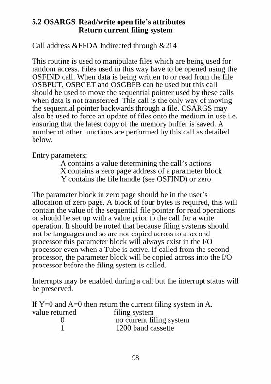
98
5.2 OSARGS Read/write open file’s attributes Return current filing system Call address &FFDA Indirected through &214 This routine is used to manipulate files which are being used for random access. Files used in this way have to be opened using the OSFIND call. When data is being written to or read from the file OSBPUT, OSBGET and OSGBPB can be used but this call should be used to move the sequential pointer used by these calls when data is not transferred. This call is the only way of moving the sequential pointer backwards through a file. OSARGS may also be used to force an update of files onto the medium in use i.e. ensuring that the latest copy of the memory buffer is saved. A number of other functions are performed by this call as detailed below. Entry parameters:
A contains a value determining the call’s actions X contains a zero page address of a parameter block Y contains the file handle (see OSFIND) or zero
The parameter block in zero page should be in the user’s allocation of zero page. A block of four bytes is required, this will contain the value of the sequential file pointer for read operations or should be set up with a value prior to the call for a write operation. It should be noted that because filing systems should not be languages and so are not copied across to a second processor this parameter block will always exist in the I/O processor even when a Tube is active. If called from the second processor, the parameter block will be copied across into the I/O processor before the filing system is called. Interrupts may be enabled during a call but the interrupt status will be preserved. If Y=0 and A=0 then return the current filing system in A. value returned filing system 0 no current filing system 1 1200 baud cassette

99
2 300 baud cassette 3 ROM filing system 4 Disc filing system 5 Econet filing system 6 Telesoftware filing system 7 IEEE filing system 8 ADFS 9 Reserved 10 Acacia RAM filing system If Y=0 and A= 1 then return the address in the I/O processor of the rest of the command line will be returned in the two least significant bytes of the zero page parameter block. This enables software to access the parameters passed with ‘*’ commands. If Y=0 and A=&FF then update all files onto the filing system medium; this ensures that the medium has the latest copy of the buffers. If Y is non-zero then the value in Y is assumed to be a file handle (see OSFIND). The value passed in A determines the action on the open file specified by Y A=0 Read sequential file pointer (written to the zero page parameter block). This pointer is the same as that used by BASIC called PTR#. A=1 Write sequential file pointer. A=2 Read length of sequential file. This value is the same as that returned by EXT# in BASIC.

100
A=3 Write length of sequential file. This call is not implemented in all filing systems but where implemented may be used either to truncate a file or to extend it (in which case it will be padded with zeroes). A= &FF Update this file onto the filing system medium. On exit:
A is preserved except on a call with A=0 and Y=0 X and Y are preserved
C, N, V and Z are undefined
D=0 5.3 OSBGET Get a single byte from an open file Call address &FFD7 Indirected through &216 This routine returns the value of a byte read from a file opened for random access. The file should have been previously opened using OSFIND, The file handle required by this call will have been provided from this OSFIND call. Entry parameters:
Y contains file handle A byte is read from that point in the file determined by the sequential file pointer. During each call of OSB GET the sequential file pointer is incremented by one. Thus successive OSBGET calls can be used to read bytes from the file sequentially. This pointer may be read or written using the OSARGS call thus enabling the use of random access. Interrupts may be enabled during a call but the interrupt status will be preserved.

101
A is returned containing the value of the byte read. On exit:
X and Y are preserved C= 1 if the end of file was reached i.e. invalid call , in which case A=&FE.
N, V and Z are undefined
5.4 OSBPUT Write a single byte to an open file Call address &FFD4 Indirected through &218 This call is the complement to the OSBGET call described above. A file handle should be provided from a prior OSFIND call and the sequential file pointer is used to locate the point in the file where the byte is written. Entry parameters:
A contains the byte to be written to the file. Y contains the file handle.
During the call a byte will be written to the file and the sequential pointer will be incremented. If the sequential file pointer reaches the end of the file the file will be extended to accommodate any new data written where possible. Interrupts may be enabled during a call but the interrupt status will be preserved over a call. On exit:
A, X and Y are preserved
C, N, V and Z are undefined

102
5.5 OSGBPB Read/write a group of bytes to/from an open file Call address &FFD1 Indirected through &21A This routine enables the transfer of a group of bytes to or from an open file. This routine is implemented particularly for filing systems which have a high time overhead associated with each data transfer e.g. the Econet. Entry parameters:
A contains a value which determines the action performed X+Y contain a pointer to a parameter block in memory
The parameter block should contain information in the following format: &00 file handle &01 - &04 address of data for transfer &05 - &08 number of bytes to transfer &09 - &0C sequential file pointer to be used The bytes in each parameter should be placed least significant byte first. The address should include a high order address (see OSBYTE &82) to indicate if the data is in an i/o processor or a second processor. The sequential file pointer passed in the parameter block will only replace the old value of this pointer when appropriate. The action codes passed to the routine will have the following effects:

103
A=1 Write a group of bytes to the open file. The sequential pointer given will indicate the point in the file where these bytes are put and this pointer will be incremented by the number of bytes written. A=2 Write a group of bytes to the open file without using the sequential file pointer value given in the parameter block. The existing value of the pointer will mark the point in the file where these bytes are put and the pointer will then be incremented by the number of bytes written. A=3 Read a group of bytes from an open file. The sequential pointer given in the parameter block will indicate where the bytes should be read from within the file. The pointer will then be incremented by the number of bytes read. A=4 Read a group of bytes from an open file disregarding the sequential file pointer value given in the parameter block. The existing pointer value will be used and subsequently incremented by the number of bytes read. A=5 Return the title associated with the currently active medium and return boot/startup attribute, This information is written to the address pointed at by the X and Y registers. The format of the data is: &00 n, the length of the title string &01 - n+1 the title string, ASCII characters n+2 value indicating boot/start up options The start up information is filing system dependent.

104
A=6 Return the currently selected directory and device identity. Two items of data are written to the parameter block. The format of the data is: &00 n, the length of the directory name &01 - n+1 directory name, ASCII string n+2 m, the length of the device identity n+3 - n+m+3 the device identity A=7 Read the currently selected library, and device, The data format is the same as that used for A=6. A=8 This call is used to read file names from the current directory. The parameter block should be set up so that the number of file names to transfer is placed in the ‘No. of bytes to transfer’ field, For the first call the ‘sequential file pointer’ field should be set to zero. The sequential file pointer is incremented each time this call is made so that it points to the next file name for transfer. The data is transferred to the specified address in the form of a list of file names. Each file name takes the form of an ASCII string preceded by a single byte value indicating the length of the string. The number of filenames in this list is determined by the value passed in the parameter block unless the end of the directory is reached. This call also returns a cycle number in the ‘file handle’ field of the parameter block. This cycle number represents the number of times the current catalogue has been written to.

105
Exit conditions: A, X and Y are preserved N, V and Z are undefined C= 1 if the transfer could not be completed
In the event of a transfer not being completed the parameter block contains the following information: (a) the number of bytes or names not transferred in the ‘number
of bytes to transfer’ field (b) the ‘address’ field contains the next location of memory due
for transfer (c) the ‘sequential pointer’ field contains the sequential file
pointer value indicating the next byte in the file due for transfer
5.6 OSFIND Open or close file for random access Call address &FFCE Indirected through &21C This call is used to allocate a file handle for subsequent use by OSARGS, OSBGET, OSBPUT and OSGBPB. This call should also be used to close a file when no further access is required. In this instance the file handle is released for re-allocation and the file medium is updated from the buffers in memory. The file handle is a single byte value which uniquely identifies an open file. This provides a less cumbersome method of addressing the file in question than using the filename each time. The number of files which can be open at any one time is filing system dependent. The actual range of handle values allocated by each filing system is different. The ranges which have been allocated by Acorn are listed under OSFSC with A=&07.

106
Entry parameters (a) To open a file The accumulator contains a code indicating the type of access for which the file should be opened: A=&40 input only A=&80 output only (i.e. will attempt to delete file first) A=&C0 input and output X and Y contain the address of a file name string (low byte, high byte). The filename string should be terminated by a carriage return character (&0D). The accumulator will be returned containing the file handle which has been allocated or zero if the file could not be opened. Note that if the filename is syntactically bad, or involves a non-existent directory, a BRK ‘Not found’ error may occur. (b) To close a file A=0 Y contains the handle of the file to be closed or Y=O to
close all currently open files. On exit:
A returns file handle on opening otherwise preserved X and Y are preserved
C, N, V and Z are preserved Interrupts may be enabled during call, status preserved
5.7 OSFSC Miscellaneous filing system control No OS call address Indirected through &21E This vector contains an entry point into the current filing system which may be used to invoke a number of miscellaneous filing system functions. Because there is no direct call address this call can only be made from within an I/O processor and is not

107
available for code running on a second processor. However many of the facilities are indirectly available via other OS calls which subsequently make calls through this vector. Entry parameters: The accumulator contains an action code determining which control function is performed. A=0 *OPT command The operating system makes this call in response to ‘*OPT’ being submitted to the command line interpreter or in response to OSBYTE &8B. X and Y contain the parameters passed with the ‘*OPT’ command. A= 1 Check for end of file (EOF) This call is made by the operating system in response to OSBYTE &7F. The call is entered with a file handle value in the X register. The X register should be returned containing the value &FF if an EOF condition exists, otherwise it should be returned containing zero. A=2 ‘*/’ command The filing system should attempt to *RUN the file whose name follows the ‘/’ character. The operating system command line interpreter will make this call in response to a command beginning ‘*/’. The X and Y registers contain the address of the file name string (not including the ‘*/’ characters). A=3 Unrecognised *command The operating system issues this call when an unrecognised command has been submitted to the command line interpreter. This call is made after the ‘unrecognised *command’ paged ROM service call has been made (see paged ROMs section 10.1). The command name string is addressed by the X and Y registers.

108
Filing systems will respond to this call by attempting to *RUN the file having the command name. The idea behind this is to enable the implementation of command like utilities which are stored on the filing system media. However in the case of a filing system being unable to execute the file without delay the filing system should respond to this call with a ‘Bad Command’ message instead. A=4 *RUN attempted The operating system passes on the file name given with a *RUN command to the current filing system using this call. The X and Y registers contain the address of the file name string, The filing system should then load and execute the code in this file. A=5 *CAT attempted This call is made by the operating system in response to a *CAT command. The X and Y registers contain the address of the rest of the command string where any parameters required by the routine may be found. A=6 New filing system selected This call is issued when the current filing system is being changed. The deselected filing system should respond by closing any *SPOOL or *EXEC files using OSBYTE &77 and prepare itself for the handover. A=7 Return handle range This call may be made to determine the range of values allocated as file handles by the currently selected filing system. Below is a list of the handle ranges that have been allocated by Acorn. filing system handle range, inclusive Tape filing system 1 (&01) 2 (&02) *ROM filing system 3 (&03) 3 (&03) Teletext filing system 14 (&0E) 15 (&0F) Disc filing system 17 (&12) 21 (&15) Network filing system 32 (&20) 39 (&29)

109
Winchester DFS 48 (&30) 57 (&39) reserved values 64 (&40) 71 (&49) Acacia RAM filing system 96 (&60) 101 (&65) IEEE filing system 240 (&F0) 255 (&FF) The X register is returned with the lowest value which may be allocated as a file handle and the Y register returned with the highest value used. A=8 OS *command about to be processed The operating system makes this call prior to executing a *command. Acorn DFS uses this call to implement the ‘*ENABLE’ protection mechanism. This call may also be used by filing systems to output extra messages e.g. ‘Compaction recommended’ when free space has become highly fragmented on a disc. On exit:
Registers returned as described above Otherwise registers undefined Status flags undefined Interrupts may be enabled, status preserved

110
6 Operating System Vectors
Many of the operating system routines are indirected through addresses stored in RAM. This enables other software to intercept these calls as they are made. During a reset the operating system stores the addresses of its internal routines for such things as reading and writing characters in locations in page two. The official entry point of these routines point to instructions like JMP (vector). If another piece of software replaces the address stored in the vector then each subsequent call is passed to the intercepting software. Consider the following example: This program assembles a routine which intercepts ‘$’ and ‘£’ characters passed to the OSWRCH routine and exchanges them. 10 DIM code% 100 20 WRCHV=&20E 30 FOR opt%=0 TO 3 STEP3 40 P%=code% 50 [ 60 OPT opt% 70 .init LDA WRCHV \ A=lo byte of vector 80 STA ret_vec \ make a copy 90 LDA WRCHV+1 \ A=hi byte of vector 100 STA ret_vec+1 \ make a copy 110 LDX #intrcpt AND &FF \ X=lo byte of new routine 120 LDY #intrcpt DIV &100 \ Y=hi byte of new routine 130 SEI \ disable interrupts 140 STX WRCHV \ store new routine address 150 STY WRCHV+1 \ in WRCH Vector 160 CLI \ enable interrupts 170 RTS \ finished initialisation 180 .intrcpt CMP #ASC”£” \ trying to print a £ ? 190 BEQ pound \ if so branch 200 CMP #ASC”$” \ trying to print a $ ? 210 BEQ dollar \ if so branch 220 JMP (ret_vec) \ neither goto old routine

111
230 .pound LDA #ASC”$” \ replace £ with $ 240 JMP (ret_vec) \ goto old routine 250 .dollar LDA #ASC”£” \ replace $ with £ 260 JMP (ret_vec) \ goto old routine 270 .ret_vec EQUW 0 \ space for return vector 280 ] 290 NEXT 300 CALL init This program, although not very long, illustrates a few points regarding the way in which vectors should be intercepted. One of the most important aspects concerning the interception of calls through vectors is to make sure that the call is passed on to the previous owner of the vector. There are occasions when a routine is intended to be the sole replacement of a vector but as a rule it is good programming practice to copy the old vector contents to a returning vector. By returning via the old vector contents any number of intercepting routines can be daisy chained into the operating system call. While the initialising routine is changing the vector contents to point at the new routine it is wise to disable interrupts, It would obviously be quite catastrophic if the OSWRCH routine were to be called when the vector was only half changed. An interrupt handling routine is unlikely to use the WRCHV but there is no reason why it should not. The intention in this section has been to make programmers aware of the problems which may occur when intercepting these vectors. They have been implemented so that they may be used to insert extra code into some of the operating system routines and individuals should not be afraid of using them to this end. However, careful thought is required; take full account of the ramifications of altering the operating systems usual response to calls. If in doubt try out a routine. Play about with trivial examples such as the one given above. There is nothing to be lost and much to be learnt.
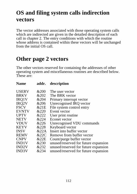
112
OS and filing system calls indirection vectors The vector addresses associated with those operating system calls which are indirected are given in the detailed description of each call in chapter 2. The entry conditions with which the routine whose address is contained within these vectors will be unchanged from the initial OS call.
Other page 2 vectors The other vectors reserved for containing the addresses of other operating system and miscellaneous routines are described below. These are: Name addr. description USERV &200 The user vector BRKV &202 The BRK vector IRQ1V &204 Primary interrupt vector IRQ2V &206 Unrecognised IRQ vector FSCV &21E File system control entry EVNTV &220 Event vector UPTV &222 User print routine NETV &224 Econet vector VDUV &226 Unrecognised VDU commands KEYV &228 Keyboard vector INSV &22A Insert into buffer vector REMV &22C Remove from buffer vector CNPV &22E Count/purge buffer vector IND1V &230 unused/reserved for future expansion IND2V &232 unused/reserved for future expansion IND3V &234 unused/reserved for future expansion
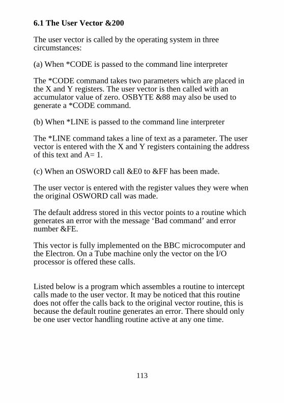
113
6.1 The User Vector &200 The user vector is called by the operating system in three circumstances: (a) When *CODE is passed to the command line interpreter The *CODE command takes two parameters which are placed in the X and Y registers. The user vector is then called with an accumulator value of zero. OSBYTE &88 may also be used to generate a *CODE command. (b) When *LINE is passed to the command line interpreter The *LINE command takes a line of text as a parameter. The user vector is entered with the X and Y registers containing the address of this text and A= 1. (c) When an OSWORD call &E0 to &FF has been made. The user vector is entered with the register values they were when the original OSWORD call was made. The default address stored in this vector points to a routine which generates an error with the message ‘Bad command’ and error number &FE. This vector is fully implemented on the BBC microcomputer and the Electron. On a Tube machine only the vector on the I/O processor is offered these calls. Listed below is a program which assembles a routine to intercept calls made to the user vector. It may be noticed that this routine does not offer the calls back to the original vector routine, this is because the default routine generates an error. There should only be one user vector handling routine active at any one time.
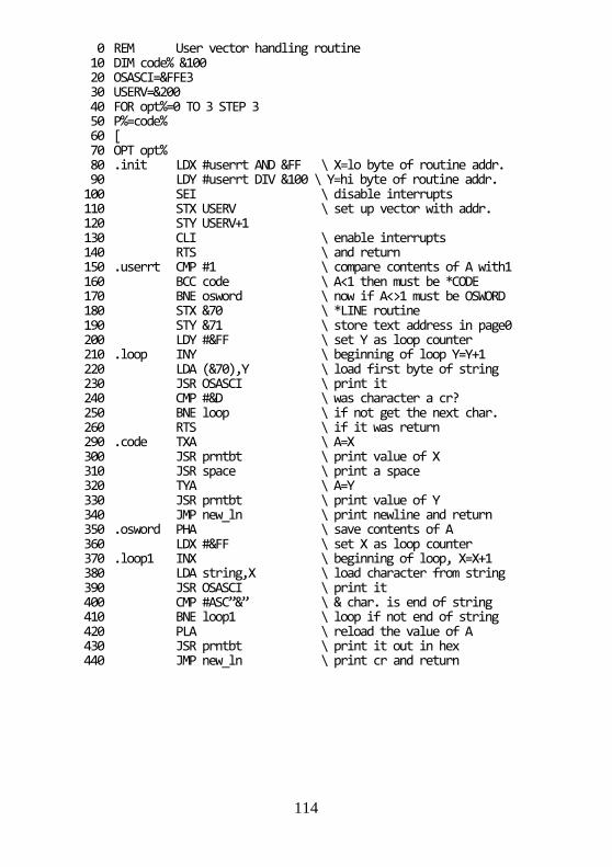
114
0 REM User vector handling routine 10 DIM code% &100 20 OSASCI=&FFE3 30 USERV=&200 40 FOR opt%=0 TO 3 STEP 3 50 P%=code% 60 [ 70 OPT opt% 80 .init LDX #userrt AND &FF \ X=lo byte of routine addr. 90 LDY #userrt DIV &100 \ Y=hi byte of routine addr. 100 SEI \ disable interrupts 110 STX USERV \ set up vector with addr. 120 STY USERV+1 130 CLI \ enable interrupts 140 RTS \ and return 150 .userrt CMP #1 \ compare contents of A with1 160 BCC code \ A<1 then must be *CODE 170 BNE osword \ now if A<>1 must be OSWORD 180 STX &70 \ *LINE routine 190 STY &71 \ store text address in page0 200 LDY #&FF \ set Y as loop counter 210 .loop INY \ beginning of loop Y=Y+1 220 LDA (&70),Y \ load first byte of string 230 JSR OSASCI \ print it 240 CMP #&D \ was character a cr? 250 BNE loop \ if not get the next char. 260 RTS \ if it was return 290 .code TXA \ A=X 300 JSR prntbt \ print value of X 310 JSR space \ print a space 320 TYA \ A=Y 330 JSR prntbt \ print value of Y 340 JMP new_ln \ print newline and return 350 .osword PHA \ save contents of A 360 LDX #&FF \ set X as loop counter 370 .loop1 INX \ beginning of loop, X=X+1 380 LDA string,X \ load character from string 390 JSR OSASCI \ print it 400 CMP #ASC”&” \ & char. is end of string 410 BNE loop1 \ loop if not end of string 420 PLA \ reload the value of A 430 JSR prntbt \ print it out in hex 440 JMP new_ln \ print cr and return

115
450 .space LDA #&20 \ A=space character 460 JMP OSASCI \ print space and return 470 .new_ln LDA #&D \ A=carriage return character 480 JMP OSASCI \ print cr and return 490 .string EQUS “OSWORD &“ \ string for OSWORD routine 499 \*** This routine prints hex number given in A 500 .prntbt PHA \ save copy of accumulator 510 LSR A 520 LSR A 530 LSR A 540 LSR A \ shift nibble hi to lo 550 JSR nibble \ print hi nibble hex digit 560 PLA \ reload accumulator 570 .nibble AND #&0F \ mask out high nibble 580 CMP #&0A \ digit or letter? 590 BCC number \ A<10 print number 600 ADC #&06 \ otherwise add 7 (C=1) 610 .number ADC #&30 \ add &30 to convert to ASCII 620 JMP OSASCI \ print character and return 630 ] 640 NEXT 650 CALL init
Once assembled this routine will respond to *CODE by printing out the parameters passed with the command. A *LINE command will result in the parameter string being repeated on the screen and an OSWORD in the region &E0 to &FF will print out the number of the call. e.g. >*CODE 1,2 01 02 >*LINE SOME TEXT SOME TEXT >A%=&E0:CALL &FFF1 OSWORD &E0 >

116
6.2 The BRK Vector &202 When a BRK instruction (op code value 0) is executed an interrupt is generated. The operating system stores the address of the byte following the BRK instruction in &FD and &FE, offers the BRK to paged ROMs with service call &06, stores the ROM number of the currently active paged ROM for recovery using OSBYTE &BA (ROM active at last BRK), restores registers, selects the current language ROM and then passes the call to the BRKV code. The BRK instruction is normally used on Acorn machines to represent an error condition and the BRK vector routine is an error handling routine. In BASIC this error handling routine starts off by putting its house in order and then prints out an error message. In addition to the use of BRKs for the generation of errors it is often useful in machine code programming to include BRKs (break-points) as a debugging aid. If a BRK instruction is executed on the Electron, the BRK vector is entered with the following conditions: (a) The A, X and Y registers are unchanged from when the BRK instruction was executed. (b) An RTI instruction will return execution to the address two bytes after the BRK instruction (i.e. jumps over the byte following the BRK). The RTI instruction also restores the status register value from the stack. (c) The address of the byte following the BRK instruction is stored in zero page locations &FD and &FE, This address can then be used for indexed addressing. Error handling BRK routines should not return to the code which executed the BRK but should reset the stack (using a TXS instruction) and JMP into a suitable reset entry point. In fact the convention used by Acorn is to follow the BRK instruction by:

117
a single byte error number an error message a zero byte to terminate the message and the BRK routine prints out the error name. The BRK handling routine should normally be implemented by the current language. Service paged ROMs should copy a BRK instruction followed by the error number and message down into RAM when wishing to generate an error. This has to be done because otherwise the current language ROM is paged in and the BRK handling routine tries to print out the error message from the wrong ROM. The bottom of page 1 is often used and is quite safe as long as the BRK handling routine resets the stack pointer. The use of BRKs as break-points in machine code programming can be of great use to the machine code programmer. The example below shows how a BRK handling routine may be used to print out the register values. This routine could be further enhanced by printing out the value of the byte following the BRK instruction which would then give the programmer 256 individually identifiable break-points. 10 REM Primitive BRK handling routine 20 DIM code% &100 30 OSASCI=&FFE3 40 OSRDCH=&FFE0 50 BRKV=&202 60 FOR opt%=0 TO 3 STEP 3 70 P%=code% 80 [ 90 OPT opt% 100 .init LDX #brkrt AND &FF \ load registers with address 110 LDY #brkrt DIV &100 120 SEI \ disable interrupts 130 STX BRKV \ set up BRK vector 140 STY BRKV+1 150 CLI \ enable interrupts and return 160 RTS 170 .brkrt PHA \ save A CX and Y not used) 180 STA byte \ store A in workspace 190 LDA #ASC”A” \ register id 200 JSR prntrg \ print register value 210 STX byte \ store X in workspace 220 LDA #ASC”X” \ register id

118
230 JSR prntrg \ print register value 240 STY byte \ store Y in workspace 250 LDA #ASC”Y” \ register id 260 JSR prntrg \ print register value 270 JSR newln \ print carriage return 280 JSR OSRDCH \ wait for key press 290 PLA \ restore A 300 RTI \ return 310 .prntrg JSR OSASCI \ print register id 320 LDA #ASC”:” 330 JSR OSASCI \ print colon 340 JSR space \ print space 350 LDA #ASC”&” 360 JSR OSASCI \ print ampersand 370 LDA byte \ get register value 380 JSR prntbt \ print hex number 390 JSR space 400 JSR space \ print two spaces 410 RTS 420 .space LDA #&20 430 JMP OSASCI \ print space 440 .newln LDA #&D 450 JMP OSASCI \ print carriage return 460 .prntbt PHA \ for comments refer to 470 LSR A \ previous example 480 LSR A 490 LSR A 500 LSR A 510 JSR nibble 520 PLA 530 .nibble AND #&0F 540 CMP #&0A 550 BCC number 560 ADC #&06 570 .number ADC #&30 580 JMP OSASCI 590 .byte EQUB 0 \ workspace byte 600 .test BRK \ cause an error 610 EQUB 0 \ RTI returns to next byte 620 DEX \ Loop X times 630 BNE test \ if X=0 Loop again 640 RTS 650 ] 660 NEXT 670 CALL init
680 A%=1:X%=8:Y%=&FF:CALL test

119
6.3 The interrupt vectors, IRQ1V &204 and IRQ2V &206 The interrupt system on the Electron is described in chapter 7. The function of the two interrupt vectors are described there. 6.4 The event vector, EVNTV &220 This vector is called by the operating system during its interrupt routine to provide users with an easy to use interrupt, A number of ‘events’ may cause the event handling routine to be called via this vector but unlike an interrupt the reason for the call is passed to the routine. The value in the accumulator indicates the type of event:
event no. cause of event
0 output buffer becomes empty 1 input buffer becomes full 2 character entering input buffer 3 ADC conversion complete 4 start of VSYNC 5 interval timer crossing zero 6 ESCAPE condition detected 7 RS423 error detected 8 Econet event 9 user event
To avoid unnecessary and time consuming calls to the event vector two OSBYTE calls are used to enable and disable these event calls being made. These are &D (13) for disabling and &E (14) for enabling events. The event handling routine should not enable interrupts and not last for more than about 2 milliseconds. So that event handling routines may be daisy chained they should preserve registers and return using the old vector contents.

120
Output buffer empty 0 This event enters the event handling routine with the buffer number (see OSBYTE &15/*FX21) in X. It is generated when a buffer becomes empty (i.e. just after the last character is removed). Input buffer full 1 This event enters the event handling routine with the buffer number (see OSBYTE &15, *FX 21) in X. It is generated when the operating system fails to enter a character into a buffer because it is full. Y contains the character value which could not be inserted. Character entering input buffer 2 This event is normally generated by a key press and the ASCII value of the key is placed in Y. It is generated independently of the input stream selected. ADC conversion complete 3 When an ADC conversion is completed on a channel this event is generated. The event handling routine is entered with the channel number on which the conversion was made in Y. This event is generated by the Plus 1 expansion software. Start of vertical sync 4 This event is generated 50 times per second coincident with vertical sync. One use of this event is to time the change to a video ULA register so that the change to the screen occurs during fly back and not while the screen is being refreshed. This avoids flickering on the screen.

121
Interval timer crossing zero 5 This event uses the interval timer (see OSWORD calls &3 and &4, in chapter 4). This timer is a 5 byte value incremented 100 times per second. The event is generated when the timer reaches zero. ESCAPE condition detected 6 When the ESCAPE key is pressed or an ESCAPE is received from the RS423 (if RS423 ESCAPEs are enabled) this event is generated. RS423 error event 7 This event should be generated by software servicing expansion RS423 hardware. Network error event 8 This event is generated when a network event is detected. If the net expansion is not present then this could be used for user events. User event 9 This event number has been set aside for the user event, This is most usefully generated from a user interrupt handling routine to enable other user software to trap an interrupt easily (e.g. an event generated from an interrupt driven utility in paged ROM). An event may be generated using OSEVEN, see section 2.10 6.5 User print vector, UPTV &222 A user print routine can be implemented by intercepting this vector, Whenever a change in printer type is made using OSBYTE &05 the print vector is called. A user print routine should respond when printer type 3 is called.

122
The operating system will activate the user printer routine and there after call it regularly at intervals of 10 milliseconds. Characters will be placed in the printer buffer and it is up to the user printer routine to remove characters and send them to the printer hardware. When the printer routine finds that the buffer is empty it should then declare itself inactive. The operating system will then re-activate the routine when characters start entering the buffer again. The user printer driver should preserve all registers and return via the old UPTV value. On entry:
X contains the buffer number to be used Y contains the printer number (i.e. the *FX 5 value)
N. B. The routine should only respond if it recognises the printer number as its own. The accumulator contains a reason code for the call: A=0 When the printer driver is active the operating system makes this call every 10 ins. The printer driver should examine its hardware and if it is ready for another character should remove a character from the assigned buffer and send it to the printer. A call to the REMV vector should be made to obtain the character (see section 6.9.2) or use OSBYTE &91, When the printer driver has emptied the printer buffer it should then declare itself inactive by making an OSBYTE call &7B. This will allow the user to select a new printer driver using OSBYTE &5, will stop further calls with A=0 and thereafter when the printer buffer is used again will cause a call with A=1 to be made (see below). A=1 When a printer driver is inactive this call is made to tell the routine that the printer buffer is no longer empty and the printer driver should now become active. If the printer driver is able to become active it should remove a character from the assigned

123
buffer and if the buffer is still not empty it should return with the carry flag clear to indicate that it is now active. Having thus signalled itself as active the printer driver will receive the 10 ms calls with A=0. A=2 When the VDU drivers receive a VDU2 this call is made. Characters may be printed even when this control character has not been received if certain *FX3 options are selected. A=3 This call is made when a VDU3 is received. A=5 The selection of a new printer driver will cause this call to be made to the printer vector. Any OSBYTE &5 call causes this call to be made. 6.6 Econet vector, NETV &224 The Econet vector allows the Network filing system to intercept a wide range of operating system functions. This vector is called with a reason code in the accumulator. The conditions under which this vector is called are: A=0, 1, 2, 3 and 5 These codes are used to control the net printer. These calls are made under identical circumstances as for the user print vector described above. The net printer is assigned the printer number 4. A=4 OSWRCH call made. This call is indirected through the net vector after OSBYTE &D0 has been used. The Y register contains the value originally passed in the accumulator. If, on exit, the carry flag is set then the output call is not performed.

124
A=6 OSRDCH call made. This call is indirected through the net vector after OSBYTE &CF has been used. The ASCII value for a key read should be returned in the accumulator. A=7 OSBYTE call made. This indirection is performed after OSBYTE &CE has been used. The OSBYTE parameters are stored in locations &EF, &F0 and &F1. If the overflow flag is set on return from this call then the OSBYTE call is not performed. A=8 OSWORD call made. Circumstances as for call with A=7. A=&0D After completion of a line of input using OSWORD &01 this call is made. This is implemented so that the Network filing system doesn’t takeover the RDCH routine in the middle of line input. 6.7 VDU extension vector, VDUV &226 This vector is called when the VDU drivers are presented with an unknown command or a known command in a non-graphics MODE. A VDU 23,n command with a value of n in the range 2 to 31 will cause a call to be made to this vector with the carry flag set. The accumulator will contain the value n. An unrecognised PLOT command or the use of a PLOT command in a non-graphics MODE will result in this call being made with the carry flag clear. The accumulator will contain the PLOT number used.

125
6.8 The keyboard vector, KEYV &228 This vector is used whenever the keyboard is being looked at. There are four different calls made through this vector on the Electron. (a) Test SHIFT and CTRL keys On entry: C=0, V=0 Should exit with the N (negative) flag set if the CTRL key is pressed and with the V (overflow) flag set if the SHIFT key is pressed. (b) Scan keyboard as for OSBYTE &79 On entry: C=1 , V=0 other parameters identical to OSBYTE &79 Should exit with the appropriate register values (see OSBYTE details) but with A=X. (c) Timer interrupt service with keys active On entry: C=1, V=1 This entry is actually used for the bulk of all keyboard processing. After an interrupt the actual keyboard scan is carried out during this call. If the user’s program does not require use of the keyboard, intercepting this call to the KEYV routine and returning it speeds up the machine enormously. Alternatively, OSBYTE 178 may be used to switch off the interrupt altogether (see Chapter 3). The keyboard may still be read by direct access to it, see section 14.2. (d) Timer interrupt service with no keys active On entry: C=0, V=1

126
6.9 The buffer maintenance vectors This vector and the two following vectors enable the user to intercept or use the operating system buffer maintenance routines. The operating system uses buffers for keyboard input, RS423 input and output, the printer, the sound system (4 buffers) and the speech system. These buffers contain data which should be processed by the various routines. Even though the servicing routine may not be able to respond to the request immediately the calling routine returns (unless the buffer is full) and is able to get on with its foreground task. While a buffer contains a queue of data for processing, the interrupt routine (the background task) sees to it that the relevant routines service this data. In this way the user is able to type ahead when the machine is unable to respond immediately and may initiate sounds which then continue while he issues further commands. Buffers operate on a first in first out (FIFO) basis for obvious reasons. The Acorn BBC range of machines use the following numbers as buffer IDs: title number keyboard buffer 0 RS423 input buffer 1 RS423 output buffer 2 printer buffer 3 SOUND channel 0 buffer 4 SOUND channel 1 buffer 5 SOUND channel 2 buffer 6 SOUND channel 3 buffer 7 speech buffer 8 On the BBC microcomputer and the Electron memory is reserved for each of these buffers even though the software/hardware using the buffer may not be present. The buffer maintenance calls still service these buffers but the contents will not be processed by the relevant service routine. The expansion software/hardware will use the appropriate buffer when installed. Thus when the speech expansion is fitted on a BBC microcomputer the speech buffer is

127
used and on an Electron with a Plus 1 the printer buffer is used. The following OSBYTE calls may also be of interest when considering the buffer facilities: Description OSBYTE number flush selected buffer class &0F (15) flush particular buffer &15 (21) get buffer status &80 (128) insert value into buffer &8A (138) get character from buffer &91 (145) examine buffer status &98 (152) insert value into i/p buffer &99 (153) 6.9.1 Insert value into buffer vector, INSV &22A This vector contains the address of a routine which inserts a value into a selected buffer. Entry parameters: A=value to be inserted X=buffer id On exit:
A and X are preserved Y is undefined
C flag is set if insertion failed (i.e. buffer full)
6.9.2 Remove value from buffer vector, REMV &22C This vector contains the address of a routine which removes a value from the selected buffer. This routine may also be used to examine the next character to be removed from a buffer without actually removing it.

128
Entry parameters: X=buffer ID V= 1 (overflow flag set) if only examination requested
On exit:
A contains next byte to be removed (examination call) (A undefined for removal call) X is preserved Y contains the value of the byte removed from the buffer (Y undefined for examination call) C flag is set if buffer empty when call made
6.9.3 Count/purge buffer vector, CNPV &22E This vector contains the address of a routine which may be used to clear the contents of a buffer or to return information about the free space or contents of a buffer. Entry parameters: X=buffer ID V=1 (overflow flag set) to purge buffer V=0 (overflow flag clear) for count operation C=1 count operation returns amount of free space C=0 count operation returns length of buffer contents On exit:
X and Y contain value of count (low byte, high byte) X and Y are preserved for a purge operation A is undefined V and C are preserved
6.9.4 Using the buffer vectors It should be noted that none of the buffer maintenance routines check for valid buffer IDs. Using a buffer ID outside the assigned range will have undefined effects unless specifically intercepted. None of these vectors are implemented on second processors and so none of the buffer maintenance calls are sent across the Tube. Calls using the buffer vectors should always be made by code

129
resident in the I/O processor. It should be noted that considerable manipulation of the buffers may be carried out using OS routines such as OSBYTE, OSWRCH, OSWORD etc. which may affect buffer contents either directly or indirectly. Routines intercepting these vectors must always be resident on the I/O processor, ideally in service type paged ROMs. The program below illustrates how the buffer vectors can be intercepted to implement a much larger printer buffer. The standard printer buffer is less than &100 bytes long and since printers as a rule tend to be quite sluggish peripherals this buffer rapidly fills up. A buffer is required which will hold a reasonable sized listing, or a document before filling up and refusing to accept further input. Having placed the item for printing in an enlarged buffer the user may return to word processing or programming leaving the operating system to get on with the printing. The routine used below creates a buffer of variable size as defined by the variable ‘size’. The usefulness of this program is limited. For the reasons given above it will only work when run on a non-Tube machine. It will only work as long as its code is not corrupted; this means that renumbering the program after it has been run will crash the machine as BASIC tramples all over the area originally reserved for the assembled code. Similarly another language ROM is unlikely to allow the routine to run in peace. If this routine becomes corrupted the machine is totally disabled because each time a key is pressed this routine is called. Experimenting with this example will provide valuable experience in the use of critical operating system routines. One note of warning however, be sure to save a copy of the program before trying to run it; it is quite possible for the program to corrupt itself or even crash the machine irrevocably so that a power on reset is required (that is, the machine will have to be turned off, then on again). This program consists of three main routines which intercept the buffer maintenance calls for the printer buffer. Calls for any of the other buffers are carefully handed on to the original routines pointed to by the contents of the buffer vectors. An area of RAM is reserved for use as a buffer by using a DIM statement. Four bytes of zero page memory are used to house two 16 bit pointers.

130
One pointer is used as an index for the insertion of values into the buffer and the other pointer is used as an index for the removal of bytes. When a pointer reaches the end of the buffer it is pointed to the beginning again, In this way the two pointers cycle through the buffer space. A full buffer is detected by incrementing the input pointer and comparing it to the output pointer. If the two pointers are equal the buffer is full, the character cannot be inserted; the input pointer is restored. If after the removal of a character the output pointer becomes equal to the input pointer then the buffer is now empty. By using this system the full size of the buffer is always available to contain data. 10 REM user printer buffer routine 20 MODE7 30 size=&2000 40 DIM buffer size 50 DIM code% &400 60 INSV~&22A 70 RMV=&22C 80 CNPV=&22E 90 ptrblk=&80: !ptrblk=buffer+buffer*&10000 100 ip_ptr=ptrblk:op_ptr=ptrblk+2 110 FOR I=0 TO 3 STEP 3 120 P%=code% 130 [ 140 OPT I 150 .init LDA INSV \ make copies of old vector 160 STA ret1 \ contents to pass on calls 170 LDA INSV+1 180 STA ret1+1 190 LDA RMV 200 STA ret2 210 LDA RMV+1 220 STA ret2+1 230 LDA CNPV 240 STA ret3 250 LDA CNPV+1 260 STA ret3+1 270 LDX #ins AND &FF \ store address of new 280 LDY #ins DIV &100 \ routines in vectors 290 SEI \ disable interrupts 300 STX INSV 310 STY INSV+1 320 LDX #rem AND &FF 330 LDY #rem DIV &100 340 STX RMV 350 STY RMV+1 360 LDX #cnp AND &FF

131
370 LDY #cnp DIV &100 380 STX CNPV 390 STY CNPV+1 400 CLI \ enable interrupts 410 RTS \ finished 420 .wrkbt EQUB 0 \ byte of RAM workspace 430 .retl EQUW 0 \ reserve space for vectors 440 .ret2 EQUW 0 450 .ret3 EQUW 0 460 .wrngbfl PLP:PLA:JMP (ret1) \restore S & A, call OS 470 \New insert char. into buffer routine 480 .ins PHA:PHP \ save A and status register 490 CPX #3 \ is buffer id 3 ? 500 BNE wrngbfl \ if not pass to old routine 510 PLP \ not passing on, tidy stack 520 LDA ip_ptr \ A=lo byte of input pointer 530 PHA \ store on stack 540 LDA ip_ptr+l \ A=hi byte of input pointer 550 PHA \ store on stack 560 LDY #0 \ Y=0 so ip_ptr incremented 570 JSR inc_ptr \ by the inc_ptr routine 580 JSR compare \ compare the two pointers 590 BEQ insfail \ if ptrs equal, buffer full 600 PLA:PLA:PLA \ don’t need ip_ptr copy now 610 STA (ip_ptr),Y \ A off stack, insrt in bufr 620 CLC \ insertion success, C=0 630 RTS \ finished 640 .insfail PLA \ buffer was full so must 650 STA ip_ptr+1 \ restore ip_ptr which was 660 PLA \ stored on the stack 670 STA ip_ptr 680 PLA 690 SEC \ insertion fails so C=a 700 RTS \ finished 710 .wrngbf2 PLP:JMP (ret2) \ restore 5, call OS 720 \New remove char. from buffer routine 730 .rem PHP \ save status register 740 CPX #3 \ is buffer id 3 ? 750 BNE wrngbf2 \ if not use OS routine 760 PLP \ restore status register 770 BVS examine \ V=1, examine not remove 780 .remsr JSR compare \ compare i/p and o/p ptrs 790 BEQ empty \ if the same, buffer empty 800 LDY #2 \ Y=2 so that increment ptr 810 JSR inc_ptr \ routine inc’s op_ptr 820 LDY #0 \ Y=0, for next instruction 830 LDA (op_ptr),Y \ fetch character from bufr 840 TAY \ return it in Y 850 CLC \ buffer not empty, C=0 860 RTS \ return

132
870 .empty SEC \ buffer empty, C=a 880 RTS \ return 890 .examine LDA op_ptr \ examine only, so store a 900 PHA \ copy of the oip pointer 910 LDA op_ptr+1 \ on the stack to restore 920 PHA \ ptr after fetch 930 JSR remsr \ fetch byte from buffer 940 PLA \ restore ptr from stack 950 STA op_ptr+1 \ (if buffer was empty 960 PLA \ C=1 from fetch call) 970 STA op_ptr 980 TYA \ examine requires ch, in A 990 RTS \ finished 1000 .wrngbf3 PLP:JMP (ret3) \ restore 5, call OS 1010 \ New count/purge buffer routine 1020 .cnp PHP \ save status reg. on stack 1030 CPX #3 \ is buffer id 3 ? 1040 BNE wrngbf3 \ if not pass to old subr 1050 PLP \ restore status register 1060 PHP \ save again 1070 BVS purge \ if V=1, purge required 1080 BCC len \ if C=0, amount in buffer 1090 LDA ip_ptr \ o/w free space request 1100 PHA 1110 LDA ip_ptr+1 \ store ip_ptr on stack 1120 PHA 1130 LDX #0 \ X=0 for use as counter 1140 STX wrkbt \ wrkbt=0 for hi counter 1150 LDY #0 \ Y=0, so ip_ptr incr’d 1160 .loopl JSR inc_ptr \ increment ip_ptr 1170 JSR compare \ does it equal op_ptr 1180 BEQ finshdl \ if so count~free space 1190 INX \ X=X+1 1200 BNE no_inc \ if X=0 don’t inc wrkbt 1210 INC wrkbt \ hi byte of count inc’d 1220 .no_inc JMP loopi \ loop round again 1230 .finshdl PLA \ restore ip_ptr off stack 1240 STA ip_ptr+1 1250 PLA 1260 STA ip_ptr 1270 LDY wrkbt \ Y=hi byte of free space 1280 PLP \ restore status register 1290 RTS \ finished 1300 .len LDA op_ptr \ store op_ptr on stack 1310 PHA 1320 LDA op_ptr+1 1330 PHA 1340 LDX #0 \ X=0 for use as counter 1350 STX wrkbt \ wrkbt=0 hi byte of count 1360 LDY #2 \ Y=2 so op_ptr incremented 1370 .loop2 JSR compare \ are ptrs equal ?

133
1380 BEQ #nshd2 \ if so buffer empty 1390 JSR inc_ptr \ increment op_ptr 1400 INX \ increment count 1410 BNE no_inc2 \ if X=0 then increment hi 1420 INC wrkbt \ byte of count 1430 .no_inc2 JMP loop2 \ loop round again 1440 .finshd2 PLA \ restore op_ptr off stack 1450 STA op_ptr+1 1460 PLA 1470 STA op_ptr 1480 LDY wrkbt \ Y=hi byte of length 1490 PLP \ restore status register 1500 RTS \ finished 1510 .purge LDA #buffer AND &FF\ to purge buffer reset 1520 STA ip_ptr \ oip and i/p ptrs to 1530 STA op_ptr \ start of buffer 1540 LDA #buffer DIV &100 1550 STA ip_ptr+1 1560 STA op_ptr+1 1570 PLP \ restore status register 1580 RTS \ return 1590 \ Increment pointer routine. Y=0 op_ptr, Y=2 ip_ptr 1600 .inc_ptr CLC \ C=0 1610 LDA ptrblk,Y \ A=?(ptrblk+Y) 1620 ADC #1 \ A=A+1+C 1630 STA ptrblk,Y \ ?(ptrblk+Y)=A 1640 LDA ptrblk+1,Y \ A=?(ptrblk+1+Y) 1650 ADC #0 \ A=A+0+C 1660 STA ptrblk+1,Y \ ?(ptrblk+1+Y)=A 1670 CMP #(buffer+size) DIV &100 \ hi byte end of bufr 1680 BNE home \ not end of buffer 1690 LDA ptrblk,Y \ A=low byte of pointer 1700 CMP #(buffer+size) AND &FF \ end of buffer ? 1710 BNE home 1720 LDA #buffer AND &FF \ if the end of buffer has 1730 STA ptrblk,Y \ been reached set pointer 1740 LDA #buffer DIV &100 \ to the beginning again 1750 STA ptrblk+1,Y 1760 .home RTS \ return 1770 \ Compare pointers, if equal Z=1 don’t care otherwise 1780 .compare LDA ip_ptr+1 1790 CMP op_ptr+1 \ compare ptr high bytes 1800 BNE return \ if not equal return 1810 LDA ip_ptr 1820 CMP op_ptr \ compare pointr low bytes 1830 .return RTS \ return 1840 ] 1850 NEXT 1860 CALL init

134
This program requires the presence of the Plus 1 expansion to be of any use. It could however be modified to replace any of the operating system’s buffers. A paged ROM version of this program can be found in chapter 10. 6.10 Unused vectors, IND1V, IND2V & IND3V &230 These vectors are reserved by Acorn for future expansion. Software which uses these vectors cannot be guaranteed to be compatible with any future versions of operating system software or other Acorn products. 6.11 The default vector table The BBC microcomputer operating system (version 1.2 onwards) and the Electron operating system contain a table of default values in a block of data. This may be accessed using the following addresses:
&FFB6 - contains the length of the data in bytes &FFB7 - contains the low byte of the data’s address &FFB8 - contains the high byte of the data’s address

135
7 Interrupts 7.1 An introduction to interrupts An interrupt is a hardware signal to the microprocessor. It informs the 6502 that a hardware device, somewhere in the Electron or on an expansion module, requires immediate attention. When the microprocessor receives an interrupt, it suspends whatever it was doing, and executes an interrupt servicing routine. Upon completion of the servicing routine, the 6502 returns to whatever it was doing before the interrupt occurred. A simple analogy of an interrupt is a man working hard at his desk writing a letter (a foreground task). Suddenly the telephone rings (an interruption). The man has to stop writing and answer the telephone (the interrupt service routine). After completion of the call, he has to put the telephone down, and pick up his writing exactly where he left off (return from interrupt). In an Electron, the main objective is to perform foreground tasks such as running BASIC programs. This is equivalent to writing the letter in the above example. The computer may however be concerned with performing lots of other functions in the background (equivalent to the man answering the telephone). An Electron which is running the house heating system for example would not wish to keep on checking that the temperature in every room is correct — this would take up too much of its processing time. However, if the temperature gets too high or too low in any of the rooms it must do something about it very quickly. This is where interrupts come in. The thermostat could generate an interrupt, causing the computer to jump quickly to the interrupt service routine, switch a heater on or off, and return to the main program. There are two basic types of interrupts available on the 6502. These are maskable interrupts (IRQs) and non-maskable interrupts (NMIs). To distinguish between the two types, there are two separate pins on a 6502. One of these is used to generate IRQs (maskable) and the other is used to generate NMIs (non-maskable).

136
7.1.1 Non-Maskable Interrupts In order to generate a non-maskable interrupt, a piece of hardware must pull the NMI line low. This forces the 6502 to stop whatever it was doing, and to start executing the NMI service routine at &0D00. NMIs are extremely powerful, because they cannot be turned off under software control. If the ULA is currently accessing RAM to produce the video display in modes 0 to 3, it is also forced to give the memory back to the 6502. NMIs can therefore create snow on the screen - the urgency of this signal is such that even the screen cannot take priority over the interrupting device. Only very high priority devices, such as the Floppy Disc or Econet interfaces, are allowed to generate NMIs. This ensures that the 6502 is only interrupted in very urgent situations. These high priority devices are then guaranteed to get immediate attention from the 6502. To return to the main program from an NMI, an RTI instruction is executed. It is always necessary to ensure that all of the 6502 registers are restored to their original state before returning to the main program. If they are modified, the main program will suddenly find garbage in its registers in the middle of some important processing. It is highly probable that a total system crash would result from this. 7.1.2 Maskable Interrupts Maskable interrupts are similar to non-maskable interrupts in most respects. A hardware device can generate a maskable interrupt to which the 6502 must normally respond. The difference is that the 6502 can choose to ignore all maskable interrupts, if it so desires, using software control. To disable interrupts (only the maskable ones though), an SEI (set interrupt disable flag) instruction is executed. Interrupts can be re-enabled at a later time using the CLI (clear interrupt disable flag) instruction. When an interrupt is generated, the processor knows that an interrupt must have come from either the ULA, or an expansion module device. Initially though, it can’t tell where the interrupt has come from. If there was only one device that could have caused the interrupt, then there would be no problem. However,
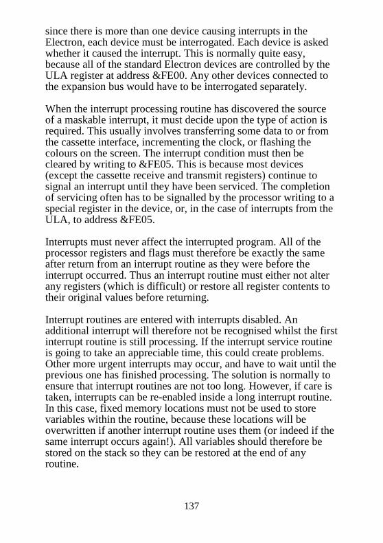
137
since there is more than one device causing interrupts in the Electron, each device must be interrogated. Each device is asked whether it caused the interrupt. This is normally quite easy, because all of the standard Electron devices are controlled by the ULA register at address &FE00. Any other devices connected to the expansion bus would have to be interrogated separately. When the interrupt processing routine has discovered the source of a maskable interrupt, it must decide upon the type of action is required. This usually involves transferring some data to or from the cassette interface, incrementing the clock, or flashing the colours on the screen. The interrupt condition must then be cleared by writing to &FE05. This is because most devices (except the cassette receive and transmit registers) continue to signal an interrupt until they have been serviced. The completion of servicing often has to be signalled by the processor writing to a special register in the device, or, in the case of interrupts from the ULA, to address &FE05. Interrupts must never affect the interrupted program. All of the processor registers and flags must therefore be exactly the same after return from an interrupt routine as they were before the interrupt occurred. Thus an interrupt routine must either not alter any registers (which is difficult) or restore all register contents to their original values before returning. Interrupt routines are entered with interrupts disabled. An additional interrupt will therefore not be recognised whilst the first interrupt routine is still processing. If the interrupt service routine is going to take an appreciable time, this could create problems. Other more urgent interrupts may occur, and have to wait until the previous one has finished processing. The solution is normally to ensure that interrupt routines are not too long. However, if care is taken, interrupts can be re-enabled inside a long interrupt routine. In this case, fixed memory locations must not be used to store variables within the routine, because these locations will be overwritten if another interrupt routine uses them (or indeed if the same interrupt occurs again!). All variables should therefore be stored on the stack so they can be restored at the end of any routine.

138
7.2 Interrupts on the Electron Interrupts are required on the Electron to process all of the background operating system tasks. These tasks include incrementing the clock, processing envelopes, or transferring keys pressed to the input buffer. All of these tasks must continue whilst the user is typing in, or running his program. Using interrupts gives the impression that there is more than one processor; one for the user, one for updating the clock, one for processing envelopes, etc. As was mentioned in the introduction, normal (maskable) interrupts can be disabled. Interrupts should only be disabled for critical operations. For example, when changing the two bytes of a vector. If an interrupt occurs in the middle of the change, it might be indirected to an erroneous address. When interrupts are disabled, the clock stops, and all other interrupt activities cease. Interrupts are disabled by the SEI assembler instruction, and re-enabled with CLI. Most devices that generate interrupts will continue to signal an interrupt until it is serviced. The cassette read register is one exception. If it isn’t serviced within 2ms, data from the cassette will almost certainly be lost forever. 7.3 Using Non-Maskable Interrupts Generally, NMIs are reserved for specialised pieces of hardware which require very fast response from the 6502. NMIs are not used on a standard system. They are used on DISC and ECONET systems. An NMI causes a jump to location &0D00 to be made. 7.4 Using Maskable Interrupts Most of the interrupts on the Electron are maskable. This means that a machine code program can choose to ignore the interrupts by disabling them. Since all of the operating system features such as scanning the keyboard, updating the clock, and running the cassette system are run on an interrupt basis, interrupts should never be disabled for more than about 2ms.

139
There are two levels of priority for maskable interrupts, defined by two indirection vectors in page &02. The priority of an interrupt indicates its relative importance with respect to other interrupts. If two devices signal an interrupt simultaneously, the higher priority interrupt is serviced first. 7.5 Intercepting interrupts Maskable interrupts can be intercepted on the Electron, and re-directed to a user specified address. This interception process consists of changing the value of a vector. There are two interrupt interception vectors called IRQ1V and IRQ2V, The first of them is indirected via the vector stored at &204,5 and the second via &206,7. If either of the vectors stored in these locations is changed to point at a user supplied routine, that user routine will be called when there is next an interrupt. Interrupt Request Vector 1 (IRQ1V) Indirects through &204,5 This is the highest priority vector through which all maskable interrupts are indirected, This is nominally reserved for the system interrupt processing routine, which copes with all of the interrupts from the ULA. Any interrupt which cannot be dealt with by the operating system routine (those which are generated by a user expansion module) are passed on through the second interrupt vector, IRQ2V. Occasionally, IRQ1V can be intercepted before the operating system gets hold of it. This will only be necessary for high priority user interrupts. Interrupt Request Vector 2 (IRQ2V) Indirects through &206,7 This vector is normally used to deal with any interrupts which cannot be dealt with by the operating system. On an unexpanded Electron, the vector simply points to a couple of lines of code to restore the A register from &FC, then return from the interrupt service.
140
Several points should be born in mind when producing interrupt service routines. a) When the vector value is changed to point at the new user
supplied routine, the previous contents of the vector should be saved somewhere. This will allow the user routine to go on to the correct address after it has finished, Note that this method of linking into IRQ1V or IRQ2V allows several independent routines to link in separately. Each stores the previous contents of the vector (which point to the next routine).
b) Disable interrupts using the SEI instruction before changing
the contents of the interrupt vectors, This is merely a precaution to guard against the possibility of interrupts occurring between writing the low and high bytes of the vector If an interrupt were to occur in the middle of this operation, the indirection vector would be erroneous, and would probably cause the machine to crash.
c) The conditions which will be in force when the user routine is
entered are that; the original 6502 status byte and return address are already stacked on the 6502 stack (ready for an RTI instruction to resume normal operation). The X and Y registers are still in their original states, but haven’t been saved anywhere. The original A register contents are in location &FC.
d) Operating system calls should not normally be made from
within an interrupt service routine, This is because they may not be re-entrant (eg. if any zero page locations are used). Most OSBYTEs and some OSWORDs are ‘IRQ-proof’. Avoid *FX0, OSBYTE &81 (positive INKEY), fast Tube BPUT, OSWORD 0, and all VDU OSWORDs except palette write/read. Such use of OS calls will often cause the foreground task to be disturbed and crash.
e) The user’s interrupt routine should be re-entrant. This means
that if there is a possibility of interrupts being re-enabled during the routine (eg. because it is very long), the code can be run again without affecting the first foreground interrupt. This can only be done by pushing the X and Y registers plus

141
the contents of &FC onto the stack, and restoring them after the call. It is also important to ensure that no fixed memory locations are used for storing variables, since these will be overwritten by an interrupting routine. The following example illustrates most of these points. When run, it will cause the Electron to make a continuous decreasing pitch tone. Several points in the program are worthy of note. The first is that IRQ1V is used instead of IRQ2V. On an unexpanded Electron, all interrupts are serviced by IRQ1V, so the OS doesn’t bother to pass them on to IRQ2V, When the tone is running, switch the listing to page mode (by pressing CTRL N). Then list the program. The sound is totally messed up because the OS is writing to the ULA as well. This illustrates one of the reasons why the official operating system calls should normally be used —to avoid clashes like that. 10 REM Interrupt utilisation example 20 REM Must operate in mode 6 30 MODE 6 40 REM Allocate space for program 50 DIM M% 100 60 FOR opt%= 0 TO 3 STEP 3 70 P%=M% 80 [ 90 OPT opt% 100 .init SEI \ Disable interrupts 110 LDA &204 \ Save old IRQ1V vector 120 STA oldv 130 LDA &205 140 STA oldv+1 150 LDA #int MOD 256 \ Low byte of address 160 STA &204 \ IRQ1V Low 170 LDA #int DIV 256 \ High byte of address 180 STA &205 190 CLI \ Turn interrupts on again 200 RTS \ Exit initialisation routine 205 210 \ This is the interrupt service routine 220 .int TXA \ Save X register 230 PHA 240 TYA \ Save Y register 250 PHA 260 INC &70 \ Counter in zero page 270 LDA &70

142
280 STA &FE06 \ Load into ULA counter 290 LDA #&32 \ Set sound mode 300 STA &FE07 \ Write to ULA control register 310 PLA \ Restore the registers 320 TAY 330 PLA 340 TAX 350 JMP (oldv) \ Go on to next service routine 355 360 .oldv EQUW 0 \ Reserve space for old vector 370 ] 380 NEXT opt% 390 REM Grab the interrupt vector 400 CALL init 410 REM Bleeping should now start 420 END

143
8 Paged ROMs The Acorn Electron and the BBC micro both support the concept of a number of ROM based programs being resident in a machine in the same address space. Each ROM is paged in as required and then paged out as software in another ROM is required. Paged ROMs work broadly in one of two ways. They act either as languages such as BASIC and LISP or they act as utilities such as filing systems and device drivers. Languages may also include such things as word processors and CAD graphics packages. At any one time only one language should be active. Thus most Electrons will enter BASIC as the default language. The current language has access or control over the user RAM which it in turn may allocate to users e.g. for BASIC programs or word processing text. While the one language is active any other ROM offering a service may be called upon as is appropriate, When a request for a service is generated the operating system interrogates each paged ROM in turn until the request is acknowledged and acted upon. Different types of request are indicated to each ROM by the operating system entering the service entry point of that ROM with an accumulator value representing the reason. These calls are called paged ROM service calls. If the service entry point is entered with A=7 this indicates that someone has asked the operating system for an OSBYTE call which the operating system failed to recognise and so is now asking the paged ROMs if they wish to claim it. If a service call is recognised then the ROM should act upon it and clear the accumulator before returning control back to the operating system. If the ROM does not wish to claim the call it should return control to the operating system with the accumulator value unchanged. There are two sets of paged ROMs, service ROMs and language ROMs. All language ROMs should respond to paged ROM service calls and so should be service ROMs as well. BASIC is an exception to this rule and the operating system recognises it by virtue of the fact that it is a language ROM not offering a service entry.

144
8.1 Paged ROM header format In order to enable the operating system to recognise ROM types and treat them accordingly, a protocol has been drawn up for a standard ROM format. ROM offset size description 0 3 language entry (JMP address) 3 3 service entry (JMP address) 6 1 ROM type flag 7 1 copyright string offset pointer (=10+t+v) 8 1 version number (binary) 9 [t] title string 9+t 1 zero byte 10+t [v] version string 10+t+v 1 zero byte 11+t+v [c] copyright string 11+t+v+c 1 zero byte 16+t+v+c 4 2nd Processor relocation address 16+t+v+c.... rest of ROM, code and data Below is a full description of each field of the paged ROM format. 8.2 Language Entry This should consist of a three byte JMP instruction referring to the language entry point. This code is called upon when a language is initialised, When a Tube is active the language may be copied across to the second processor and then entered, When a language is copied across the tube it may be relocated to a different address (see section 8.4 below). If a ROM is not a language ROM this field should contain zeros.

145
8.3 Service Entry This should consist of a three byte JMP instruction referring to the service entry point. This should point to code which responds to paged ROM service calls acting if and when appropriate. If a ROM is not a service ROM this field may contain user code. 8.4 ROM Type Byte The value of this byte gives information to the operating system about the nature of the ROM. The setting of each bit indicates a separate thing. Bit No. Meaning if set 0 processor/language bit 1 ditto 2 ditto 3 ditto 4 Controls Electron firm key expansions 5 Indicates that ROM has a relocation address 6 Indicates that this is a language ROM 7 Indicates that this ROM has a service entry The first 4 bits indicate the processor type for which the code is intended, This is of importance to second processors who may get languages copied across to them. A second processor will look for the correct value of these bits before attempting to run the language. The following values have been assigned: 0 6502 BASIC 1 reserved 2 6502 code (not BASIC) 3 68000 code 8 Z80 code 9 16032 (or 32016)

146
If bit 5 is set this indicates that the language code in this ROM has been assembled at a different address and the ROM should be copied across the Tube to the second processor to this address. Service routines are not executed from the Tube copy. If bit 6 is set this indicates that this is not a language ROM. This does not mean that the ROM cannot have a language entry point. If this bit is not set a language will not be considered for initialisation following a hard reset. However, if the language is entered via a service call (i.e. *<name> ) a soft reset will reinitialise that language. 8.5 Copyright Offset Pointer This is an offset value from the beginning of the ROM to the zero byte preceding the copyright string, It is important that this points to a zero byte followed by ‘(’, ‘C’ and ‘)’ ASCII character values because the operating system uses this fact to determine whether a ROM physically exists in a ROM position. 8.6 Binary Version Number This eight bit version number of the software contained in a ROM helps identify software. This byte is not used by any operating system and need not correspond to the version string. 8.7 Title String This is a string which is printed out as the operating system enters the ROM as a language.

147
8.8 Version String (optional) This should be a string identifying the release number of the software. The format of this string should be A.BB where A and B are ASCII characters of decimal digits. On entry to a language the error pointer is set to this or if there is no version string the error pointer is directed to the copyright string. 8.9 Copyright String This string is essential for the operating system recognition of a paged ROM (see section 8.5 above). The copyright string should always be preceded by a zero byte and start with the characters ‘(C)’. 8.10 The Tube Relocation address This is the address which is used when a ROM is relocated when copying across the Tube to a second processor. The language code should be assembled to run at that address but the service code should be assembled to run from &8000 as it will be executed within the ROM in the I/O processor. Executing Software in Paged ROMs It is possible to execute machine code in a paged ROM in one of three ways, via the language entry point after a reset, via the service entry point when the operating system performs a service call or via an extended vector (which is usually set up by a paged ROM in response to a service call). The following two chapters describe how the two types of paged ROMs may be implemented.

148
9 Language ROMs The term language ROM is something of a misnomer given most peoples’ idea of what a language is. In the context of paged ROM software the language is the primary paged ROM. Other paged ROMs may perform functions transiently but control is then returned to the current language ROM. The language ROM receives a large allocation of zero page workspace and is allocated pages 4 through to 7 as private workspace. In addition to this the language has control of the user RAM which may or may not be used as additional workspace. BASIC, for example, uses a variable portion of the user RAM (from LOMEM to HIMEM) for the storage of program variables. Languages are most typically implemented in language ROMs as would be expected. Thus BASIC, FORTH, LISP and BCPL are all language ROMs but other software implemented as language ROMs include word processors and terminal emulators. No paged ROM software should be executed unless a service call has been performed first with the possible exception of a language entered following a reset. The language entered after a hard reset will be the language ROM identified by the ROM type byte in its header occupying the highest priority socket. Following a soft reset the language active when the reset occurred will be reinitialised. Any language should respond to a *command to enable its activation when this command is issued. This mechanism allows the user to switch between languages. This command would be unrecognised by the operating system which would then issue an unrecognised * command paged ROM service call to which the language ROM would respond via its service entry point. 9.1 Language initialisation A language ROM will be entered via the language entry point with an accumulator value of &01 when the language is selected. The language is entered with a JMP instruction and no return is expected. The stack pointer should be reinitialised as the stack state is undefined on entry.

149
The language ROM should also be able to respond to service calls which may affect it (see below) e.g. be able to respond to the service call which warns of a changing OSHWM due to font explosion. 9.2 Firm keys On the Electron the function keys are implemented as a combination key press requiring the use of the CAPS LK/FUNC key with the number keys. In addition to these soft keys there are a number of non-programmable firm keys which also produce text strings when pressed. The other character keys (A to Z plus the comma, full stop and slash keys) pressed in combination with the CAPS LOCK/FUNC key constitute the firm keys. A language ROM indicates that it has the facility to expand these keys by bit 4 of the ROM type byte being set (see section 8.4). When the operating system detects that a firm key has been pressed it calls the language via its entry point to request the expansion of the key. The language should then yield the firm key string one character at a time in response to further calls. The two calls made through the language entry point are: A=2 This call expects the next key in the firm key expansion to be returned in Y. A=3, Y=firm key code This call is an initialising call. The language should return the length of the firm key string in Y.

150
The key values passed to the language with this call are: &90 to &A9 FUNC+A to FUNC+Z &AA FUNC+: &AB FUNC+; &AC FUNC+, &AD FUNC+= &AE FUNC+. &AF FUNC+/ The operating system inserts these key values into the input buffer as they are received. OSBYTE &CC (204) may be used to read or write the OS copy of its firm key pointer and OSBYTE &CD (205) may be used to read or write the length of the current firm key string being expanded. 9.3 Language ROM compatibility It is quite feasible to write a language ROM which will work with the entire range of Acorn machines supporting paged ROMs in all their configurations. The first question that a programmer should consider before implementing software in a Language type ROM is whether it actually needs to be a language ROM? Many utilities are only required transiently and it is better to implement them as service type ROMs. A routine in a service type ROM can then be used from the language environment. As has been mentioned above the language should have a service entry point so that it may be selected by a *command and be able to respond to changes in OSHWM. For information about service type ROMs read the next chapter. It must be remembered however that a language ROM is copied across to the second processor when a Tube is active. Therefore, when executing, the language must not rely on receiving service calls (i.e. the only
151
ones the language code should respond to are those of relevance when on an I/O processor such as the font explosion warning). The service code should not share or use the language work space (&400-&7FF or language zero page) because the service code is executed in the I/O processor of a Tube machine where the Tube code has the status of the current ‘language’ and the actual language is across on the second processor. The language code should not attempt to perform any manipulation of hardware by direct poking because this would make it machine dependent. The programmer may wish to implement hardware dependent routines in the service section of the ROM. The language code should communicate with the service code using unknown OSBYTE calls etc. for this purpose. It is always easier to write ROM code to create software with limited compatibility. It is often the case that software written originally with just one machine or configuration in mind will be just as useful on another machine. A programmer should always have confidence in his or her skills such that they consider the extra effort worthwhile. The discipline in thought required to adhere to the compatibility protocols represents a professional attitude. The Electron and other Acorn products were designed by experts, and while ultimately human and thus fallible, have put great consideration into making it possible to run software over a wide a range of machines.

152
10 Service ROMs Service ROMs are ROMs which contain code which is entered via the service entry point. Service ROM code will always be executed in the ROM itself i.e. always in the I/O processor c.f. language ROMs. The calls made by the operating system to service ROMs are called paged ROM service calls but will usually be referred to as just ‘service calls’. The type of software which might be implemented in service type ROMs are filing systems, user printer drivers, extension VDU commands and languages; in fact just about anything. It should be noted that extreme care should be taken to implement routines in service ROMs correctly. To understand how software can be incorporated into a paged ROM, be interfaced correctly with the operating system and thus executed at the appropriate time an understanding of paged ROM service calls is essential. When a hard reset occurs the operating system makes a note of where physical ROMs exist in paged ROM sockets. Subsequently as the machine carries out its various tasks each time something which may be of significance to software in paged ROMs occurs these ROMs are given an opportunity to respond. 10.1 Paged ROM service calls The mechanism by which this is performed is as follows. The operating system pages in each paged ROM in turn starting with that ROM in the highest priority socket (paging is performed by writing a value to a hardware latch, the hardware responds to the value written to this location and performs the relevant switching of the chip select signals). If the ROM has a service entry point this code is executed. Before entering the code the accumulator is loaded with a reason code, the X register will contain the current ROM number (a ROM is thus able to tell which socket it is in) and the Y register will be loaded with any further relevant information. The paged ROM can return control to the operating system following an RTS instruction. If the ROM has responded

153
and does not wish any further action to be taken, the accumulator should be set to zero to claim the call otherwise all registers should be unchanged. Below is a list of the reason codes which may be presented to a paged ROM when a service call is performed. Reason code &00: No operation No operation, this service call should be ignored because a higher priority ROM has already claimed it. Reason code &01: Absolute filing system space claim This call is made during a reset. The operating system is interrogating each ROM to determine how much workspace memory would be required if that ROM was called. This workspace is available temporarily while the filing system ROM is active. Pages &E00 and above are available as a fixed area on the BBC micro and the Electron. Each paged ROM is entered with A=&01 , X=ROM number and Y=top of fixed area. For the highest priority ROM on a BBC micro the Y register will contain &E. The Y register value should be increased in accordance to the requirements of the ROM. If the Y register setting is sufficient or greater than required then the service routine should return the Y register unaltered. Before using this workspace, the new filing system ROM should deselect the old filing system with OSFSC with A=6 (indirected through (&20E), see section 5.7); and the workspace must be claimed with OSBYTE &8F, X=&0A (see Reason Code &0A of this section). Reason code &02: Relative space claim This call is made by the operating system during a reset to determine how much private RAM workspace is required by each ROM. The position of this private area will start from the top of the absolute space claimed by the ROMs and on the relative

154
space claimed by higher priority ROMs. This call is made with the Y register containing the value of the first available page. This value should be stored in the ROM workspace table at &DF0 to &DFF (for ROMs 0 to 15 respectively) and the Y register returned increased by the number of pages of private workspace required. Reason code &03: Auto-boot call This call is issued during a reset to allow each service ROM to initialise itself. This enables the highest priority filing system to set up its vectors automatically rather than require explicit selection with a *command. To allow lower priority services to be selected the service ROM should examine the keyboard and initialise only if either no key is pressed or if its own ROM specific key is being pressed (e.g. D+BREAK for Acorn DFS). If the ROM initialises it should attempt to look for a boot file (typically !BOOT) to RUN, EXEC or LOAD if the Y register contains zero. This call is made during a reset after the start-up messages have been printed. Reason code &04: Unrecognised *command When a line of text is offered to the command line interpreter (CLI) the operating system will pass on any unrecognised command firstly to each of the paged ROMs and then if still unrecognised to the currently active filing system. When the unrecognised command is offered to the paged ROMs this service call is made. Entry parameters:
A=&04 X=ROM number Y contains an offset which if added to the contents of &F2 and
&F3 point to the beginning of the text with the asterisk and leading spaces stripped off and terminated with a carriage return
On exit:
Registers restored A=0 if recognized
155
Filing systems should not intercept filing system commands (which will be common to all filing systems) using this service call but may intercept some filing system utilities (e.g. *DISC, *NET). Reason code &05: Unknown interrupt An interrupt which is not recognised by the operating system or which has been masked out by software will result in this call being generated. A service ROM which services devices which might cause interrupts should interrogate such devices to determine if they have generated this interrupt. If the interrupt has been recognised and processed the accumulator should be returned with zero to prevent other ROMs being offered the interrupt. The routine should terminate with an RTS not an RTI. Reason code &06: BRK has been executed If a BRK instruction is encountered this call will be generated before indirecting through the BRK vector (BRKV, &202). BRKs are usually used to indicate that an error condition has occurred, service ROMs are informed before the current language is able to respond to the BRK via BRKV. Entry parameters:
A=&06 X=ROM number Y is undefined but should be preserved. &F0 contains the value of the stack pointer. &FD and &FE point to the error number which is not necessarily in the current ROM (OSBYTE &BA yields this ROM number)
On exit:
All registers should be preserved

156
Reason code &0: Unrecognised OSBYTE call
When an OSBYTE call has been made and is not recognised by the operating system it is offered to the paged ROMs by this service call. The contents of the A, X and Y registers at the time of the OSBYTE call are stored in locations &EF, &F0 and &F1 respectively. Reason code &08: Unrecognised OSWORD call This service call is performed in response to the user issuing an OSWORD call not catered for in the operating system. The contents of the A, X and Y registers at the time of the call are stored in locations &EF, &F0 and &F1 respectively. Unrecognised OSWORD calls with accumulator values greater than or equal to &E0 are offered to the user vector (USERV, &200). An OSWORD call with A=7 (equivalent to the SOUND command in BASIC) given an unrecognised channel will also generate this service call. Reason code &09: *HELP command interception When the *HELP command is passed through the CLI this service call is generated. The remainder of the command line is pointed to by the address stored in locations &F2 and &F3 plus an offset in Y. Each ROM is required to respond to this call. If the remainder of the command line is blank the ROM should print its name and version number followed by a list of subheadings to which the ROM will respond. e.g. Acorn DFS (version 0.90) outputs: DFS 0.90 DFS UTILS
Indicating that this ROM responds to *HELP DFS and *HELP UTILS

157
If the rest of the command line is not blank the service routine should compare it against its subheadings and if a match occurs should output the information under that subheading. e.g. Acorn DFS responds to *HELP UTILS with: DFS 0.90 BUILD <fsp> DISC DUMP <fsp> TYPE <fsp> If there is more than one item on a line then the ROM should deal with them individually. All registers should be preserved across the service routine. Reason code &0A: Claim absolute workspace This service call originates from a paged ROM which requires the use of the absolute workspace. When a filing system ROM is active and requires use of this workspace it should perform an OSBYTE call &8E with X=&0A which will generate this service call. The previous owner of the absolute workspace is then able to save any valuable contents of this memory in its own private data area in the relative workspace. The previous owner should also update a flag within its private data area indicating that it no longer owns the absolute workspace. The active filing system is selected independently of the ownership of the absolute workspace. Thus while a filing system ROM may have ownership of this workspace the tape filing system may be selected (the tape FS does not require any absolute workspace). Problems may arise when the active filing system paged ROM is called upon but does not have ownership of the absolute workspace. The active filing system should then issue this service call to obtain the use of the absolute workspace. This call should only be made by a filing system starting (see also Reason code &01).

158
Reason code &0B: NMI released This service call also originates from paged ROMs and should be generated by performing an OSBYTE call &8F. This call should be issued when a ROM no longer requires the NMI. This releases the zero page locations &A0 to &A7 and the space for the NML routine in page &D00. On entry the Y register contains the filing system number of the previous owner (see OSARGS, section 5.2) and this should be compared to the ROM’s own identity before reasserting control of the NMI. Reason code &0C: NMI claim This call should be generated by a paged ROM using OSBYTE &8F when it wishes to take possession of the NMI. The service call should be generated passing &FF in the Y register (i.e. OSBYTE A=&8F, X=&0C and Y=&FF). The current owner should relinquish control returning its filing system number in the Y register in response to this call. Reason code &0D: ROM filing system initialise When the ROM filing system (RFS) is activated in response to a *ROM command this call will be issued when a file is being searched for. On entry the Y register contains 15 minus the ROM number of the next ROM to be scanned. If this ROM number is less than the current ROM’s ID this call should be ignored. Otherwise the active ROM number should be stored in &F5 (in the form 15-ROM number) where the RFS active ROM number is stored. The current ROM should indicate that the service call has been claimed by returning zero in the accumulator and should store a pointer to the data stored within the ROM in locations &F6 and &F7 set aside for use by the RFS. See chapter 11.

159
Reason code &0E: ROM filing system get byte This service call may be issued after a ROM containing RFS data has been initialised with service call &0D, A ROM should respond only if it is the active RFS ROM as indicated by the value in location &F5 (stored in the form 15-ROM number). The fetched byte should be returned in the Y register. See chapter 11. Reason code &0F: Vectors claimed This service call should be generated by any paged ROM (using OSBYTE &8F) which has been initialised and then changed any operating system vector. This call warns paged ROMs that a vector change has occurred. Reason code &10: SPOOL/EXEC file closure warning This service call should be produced by the operating system prior to closure of any SPOOL or EXEC files when there is a change of the current filing system. This enables any paged ROM using such a file to respond to the possibly premature closure of these files. SPOOL/EXEC file closure may be prevented by returning a zero in the accumulator otherwise all registers should be preserved. Reason code & 11 : Font implosion/explosion warning When OSBYTE &14 is used to change the RAM allocation for user defined characters this service call is issued. This call is issued to warn languages that the OSHWM has been changed and thus the user RAM allocation has changed.

160
Reason code &12: Initialise filing system This call enables third party software to switch between one or more filing systems without having to issue *commands. A program may want to switch between two filing systems in order to transfer files. A filing system ROM should respond to this call if the value in the Y register corresponds to its filing system number. All filing systems should allow files to be open while inactive and so on receiving this call should restore any such files. Reason code &13: Character placed in RS423 buffer This call is made when the Electron OS has placed a character in the RS423 buffer. Expansion software handling RS423 hardware should respond to this call. If not claimed the operating system purges the RS423 buffer. Reason code &14: Character placed in printer buffer This call is made when the Electron OS has placed a character in the printer buffer. Expansion software controlling printer hardware should respond to this call. Reason code &15: 100 Hz poll The Electron operating system will provide a 100 Hz polling call for the use of paged ROMs. A paged ROM requiring this call should increment the polling semaphore using OSBYTE &16 (22) on initialisation and decrement it using OSBYTE &17 (23) when it no longer requires polling. The operating system will issue this service call when the semaphore is non-zero. The semaphore itself may be read using OSBYTE &B9 (185). This facility is implemented mainly so that hardware devices may be supported as a background task without being interrupt driven. This would be suitable for hardware not requiring particularly urgent servicing.

161
The Y register contains the semaphore value, and should be decremented by the service routine if it is being polled. If a service routine finds it has decremented the Y register to zero, it should claim the call (set A to 0) to improve machine speed (there are no more ROMs which require polling). Reason code &16: A BEL request has been made When the external sound flag (OSBYTE &DB/219) is set this call is issued by the OS in response to an ASCII BEL code being output (VDU 7). This is to enable the external sound system to respond appropriately. Reason code &17: SOUND buffer purged This call is made when an external sound system is flagged on the Electron and an attempt has been made to purge any of the SOUND buffers. Reason code &FE: Post initialisation Tube system call The operating system makes this call during a reset after the OSHWM has been set. The Tube service ROM responds to this by exploding the user defined character RAM allocation. Reason code &FF: Tube system main initialisation This call is issued only if the Tube hardware has been detected. This call is made prior to message generation and filing system initialisation. The fact that these calls are shared by all the service ROMs can lead to wide spread consequences if a service call is misused by one of the ROMs. The programmer should consider the consequences of his ROM claiming calls (or not claiming calls) when present.

162
10.2 Service ROM example The program below is a ROM based version of the enlarged printer buffer program originally described in chapter 6, and will only be of use to machines with the Plus 1 expansion. It is short by paged ROM standards but the assembler program is not a short example. This program should only be taken as an illustration of the use of some of the service calls described above : it does not conform to paged service ROM standards, as it uses Econet zero page workspace. This may be of little consequence to the vast majority of Electrons, but properly implemented service ROMs should never assume that they won’t be used with any particular system configuration. 10 REM Assembler program printer buffer ROM 20 DIM code% &400 30 INSV=&22A:nI=&2A/2 40 RMV=&22C:nR=&2C/2 50 CNPV=&22E:nC=&2E/2 60 ptrblk=&90 70 ip_ptr=ptrblk+2 80 op_ptr=ptrblk+4 90 old_bfr=&880 100 begin=old_bfr 110 end=old_bfr+2 120 wrkbt=old_bfr+4 130 size=old_bfr+5 140 vec_cpy=old_bfr+6 150 line=&F2 160 OSASCI=&FFE3 170 OSBYTE=&FFF4 180 FOR I=4 TO 7 STEP 3 190 P%~&8000:O%=code% 200 [ 210 OPT 1 220 .romstrt EQUB 0 \ null language entry point 230 EQUB 0 240 EQUB 0 250 JMP service \ service entry point 260 EQUB &82 \ ROM type byte, service ROM 270 EQUB (copyr—romstrt)\ offset to copyright string

163
280 EQUB 0 \ null byte 290 .title EQUB &A \ title string 300 EQUS “BUFFER” 310 EQUB &0 \ null byte 320 EQUS “1.00” \ version string 330 EQUB &D \ carriage return 340 .copyr EQUB 0 \ terminator byte 350 EQUS “(C)1984 Mark Holmes”\ copyright message 360 EQUB 0 \ terminator byte 370 \ End of ROM header, start of code 380 .name EQUS “REFFUB” \ command name 390 \ Service handling code, A=reason code, X=ROM id & Y=data 400 .service CMP #4 \ is reason unknown command? 410 BEQ command \ if so goto ‘command’ 420 CMP #9 \ is reason *HELP 430 BEQ help \ if so goto ‘help’ 440 CMP #2 \ is reason private wrkspace 450 BEQ wkspclm \ if so goto ‘wkspclm’ 460 CMP #3 \ is reason autoboot call 470 BNE notboot \ if NOT goto ‘notboot’ 480 JMP autorun \ BEQ autorun, out of range 490 .notboot RTS \ other reason, pass on 500 \ Unknown command, is it *BUFFER ? 510 \ (command line address in &F2,&F3 (line) + offset Y) 520 .command TYA:PHA:TXA:PHA \ save registers 530 LDX #6 \ X=length of name 540 .loopl LDA (Line),Y \ A=next Letter of command 550 CMP name—1,X \ compare with my name 560 BNE notme \ not equal, goto ‘notme’ 570 INY \ for next letter of command 580 DEX \ for next Letter of name 590 BNE loop1 \ if X<>0 round again 600 BEQ parmch \ 6 Letters matched, do jump 610 .notme PLA:TAX:PLA:TAY \ no match, restore registrs 620 LDA #4 \ restore reason code 630 RTS \ pass on call 640 \ *HELP response (parameters as for call above) 650 .he;p TYA:PHA:TXA:PHA \ save registers 660 LDX #0 \ use X as index counter 670 .loop2 LDA title,X \ A=next Letter from title $ 680 BNE over1 \ if A<>0 jump next instrctn 690 LDA #&20 \ replace 0 by space char. 700 .overl JSR OSASCI \ write character

164
710 INX \ increment index counter 720 CPX #(copyr—titLe) \ end of title ? 730 BNE loop2 \ if not get another char. 740 PLA:TAX:PLA:TAY \ restore registers 750 LDA #9 \ restore A 760 RTS \ pass on *HELP call 770 \ Opportunity to claim private workspace 780 \ (Y=1st page free, call inc’s Y by no. pages claimed) 790 .wkspclm TYA \ copy page no. to A 800 STA &DF0,X \ table for ROMs’ workspace 810 PHA \ save page no. on stack 820 LDA #&FD 830 LDX #0 840 LDY #&FF \ OSBYTE call to read last 850 JSR OSBYTE \ BREAK type 860 CPX #0 \ X=0 after soft reset 870 BEQ softrst \ soft brk, dont reset size 880 LDA #8 \ 8 pages for printer buffr 890 STA size \ location for buffer size 900 .softrst CLC \ clear carry, for add 910 PLA \ original Y on stack 920 ADC size \ A=A+?size 930 TAY \ Y=A 940 LDX &F4 \ X=ROMid 950 LDA #2 \ restore A (reason code) 960 RTS \ pass on workspace call 970 \ *BUFFER command issued, reset buffer size 980 .parmch LDA (line),Y \ get char. from cmnd line 990 CMP #&D \ car.ret.? end of line ? 1000 BNE ok_init \ if not, cont. line input 1010 LDA #1 \ no parameters so set 1020 JMP defauLt \ default buffer size 1030 .ok_init INY \ increment index counter 1040 CMP #&20 \ was char. a space? 1050 BEQ parmch \ if so get next character 1060 SEC \ set carry for subrtact 1070 SBC #&30 \ A=A—ASC”0” 1080 CMP #0 \ was character zero 1090 BEQ deinit \ if so, switch off 1100 BMI rngerr \ char.<0, out of range 1110 CMP #6 \ compare char. to 6 1120 BPL rngerr \ A>=6, out of range 1130 .default CLC \ clear carry for ASL 1140 ASL A:ASL A:ASL A \ A=A*8 1150 STA size \ store for buffer size 1160 .prntmes LDA #&87 \ Use OSBYTE &87 to read 1170 JSR OSBYTE \ current screen MODE
165
1180 TYA \ A=Y 1190 TAX \ X=A 1200 LDY #&F8 \ Use OSBYTE &FF to write 1210 LDA #&FF \ MODE selected on reset 1220 JSR OSBYTE \ (i.e. MODE preserved) 1230 TAX \ X=&FF 1240 .loop6 INX \ increment index counter 1250 LDA message,X \ A=next byte of message 1260 JSR OSASCI \ print character 1270 CMP #&D \ was it carriage return 1280 BNE loop6 \ if not get next character 1290 PLA:TAX:PLA:TAY \ restore registers 1300 LDA #0 \ claim call, 0 reason code 1310 RTS \ return 1320 .message EQUB &A \ message string 1330 EQUS “Press BREAK to change buffer size” 1340 EQUB &D 1350 .rngerr LDX #&FF \ set index counter 1360 .loop7 INX \ increment index counter 1370 LDA errdata,X \ A=character from string 1380 STA &100,X \ copy to bottom of stack 1390 CMP #&FF \ was byte terminator 1400 BNE loop7 \ if not Loop again 1410 JMP &l00 \ goto &l00 CBRK) 1420 .errdata EQUB 0 \ BRK opcode 1430 EQUB 0 \ error number 0 1440 EQUS “Invalid buffer size” \error message 1450 EQUB 0 \ message string end 1460 EQUB &FF \ terminator byte 1470 \ Routine for deselecting buffer ROM routines 1480 .deinit LDA #3 \ VDU3, just in case 1490 JSR OSASCI 1500 SEI \ disable interrupts 1510 LDY #0 1520 STY size \ size=0 1530 .loop8 LDA vec_cpy,Y \ Load old vector contents 1540 STA INSV,Y \ store in vector 1550 INY \ increment index counter 1560 CPY #6 \ copied 6 bytes yet 1570 BNE loop8 \ if not Loop again 1580 CLI \ enable interrupts 1590 JMP prntmes \ print message + return 1600 \ Initialise buffer routines automaticalLy 1610 .autorun TYA:PHA:TXA:PHA \ preserve registers 1620 LDA size \ A=buffer size in pages 1630 BEQ no_init \ A=0, don’t initialise 1640 LDA #&84 \ HIMEM OSBYTE number

166
1650 JSR OSBYTE \ make call 1660 STY end \ store page address 1670 LDA #&83 \ OSHWM OSBYTE number 1680 JSR OSBYTE \ make call 1690 CPY end \ is OSHWM > HIMEM 1700 BCC room \ if so continue 1710 JMP no_room \ no room so cause error 1720 .room JSR init \ call initialise routine 1730 .no_init PLA:TAX:PLA:TAY \ restore registers 1740 LDA #3 \ restore A 1750 RTS \ return 1760 .init LDA #&A8 1770 LDX #0 1780 LDY #&FF \ OSBYTE to read address of 1790 JSR OSBYTE \ extended vector table 1800 STX ptrblk \ set up zero page Locations 1810 STY ptrblk+l \ for indirect indexed adr. 1820 LDY #3*nI \ offset into table CINSV) 1830 LDA #ins AND &FF \ address of new routine 1840 SEI \ disable interrupts 1850 STA (ptrblk),Y \ copy address to vector 1860 INY \ Y=Y+1 1870 LDA #ins DIV &l00 \ high byte of address 1880 STA (ptrblk),Y \ copy to extended vector 1890 INY \ Y=Y+1 1900 LDA &F4 \ A=ROMid 1910 STA (ptrblk),Y \ complete extended vector 1920 INY \ Y=Y+1 1930 LDA #rem AND &FF \ REMV new routine address 1940 STA (ptrblk),Y \ lo byte to extended vector 1950 INY \ YY+1 1960 LDA #rem DIV &l00 \ Hi byte of new routine 1970 STA (ptrblk),Y \ place in extended vector 1980 INY \ Y=Y+l 1990 LDA &F4 \ A=ROMid 2000 STA (ptrblk),Y \ complete REMV 3 byte vect. 2010 INY \ Y=Y+1 2020 LDA #cnp AND &FF \ repeat, store address of 2030 STA (ptrblk),Y \ new CNPV routine in the 2040 INY \ extended vector together 2050 LDA #cnp DIV &l00 \ with ROM number. 2060 STA (ptrblk),Y 2070 INY 2080 LDA &F4 2090 STA (ptrblk),Y 2100 TAX \ X=ROMid 2110 LDY #0 \ Y=0 2120 .loop3 LDA INSV,Y \ A=old vector contents 2130 STA vec_cpy,Y \ copy to workspace 2140 INY \ Y=Y+1 2150 CPY #6 \ copied 6 bytes yet ?
167
2160 BNE Loop3 \ if not loop again 2170 LDA &DF0,X \ A=workspace addr. hi byte 2180 STA begin+1 \ store in zero page 2190 CLC \ clear carry for add 2200 ADC size \ add begin+size 2210 STA end+1:DEC end+1 \ store in zero page, —1 2220 LDY #&10 \ lo byte of begin 2230 STY begin \(room for return vect’s) 2240 LDY #&FF \ lo byte of end 2250 STY end \ store in zero page 2260 JSR rstptrs \ reset ip+op ptrs 2270 LDA #nI*3 \ for the extended vector 2280 STA INSV \ system the vectors must 2290 LDA #nR*3 \ now point to &FF00 + 2300 STA RMV \ vector number*3 2310 LDA #nC*3 2320 STA CNPV 2330 LDA #&FF 2340 STA INSV+1 2350 STA RMV+1 2360 STA CNPV+1 2370 CLI \ enable interrupts 2380 RTS \ return 2390 .noroom CLI \ clear interrupts 2430 .loop9 LDA nrmerr,X \ fetch next byte of data 2440 STA &100,X \ store at bottom of stack 2450 INX \ increment index counter 2460 CMP #&FF \ reached terminator ? 2470 BNE loop9 \ if not loop again 2480 JMP &l00 \ execute BRK (not in ROM) 2490 .nrmerr EQUB 0 \ BRK instruction opcode 2500 EQUB 0 \ error number 0 2510 EQUS “Not enough room for print buffer, Press BREAK” 2520 EQUB 0 \ string terminator 2530 EQUB &FF \ data end 2540 \ Purge buffer by setting i/p + o/p ptrs to buffer start 2550 .rstptrs LDA begin \ lo byte bufr start address 2560 STA ip_ptr \ store input pointer 2570 STA op_ptr \ store output pointer 2580 LDA begin+1 \ hi byte of buffer start 2590 STA ip_ptr+1 \ store input pointer 2600 STA op_ptr+1 \ store output pointer 2610 RTS \ return 2620 .wrngbfl PLA:PLP:JMP (vec_cpy)\ old INSV routine 2630 \ New insert char. into buffer routine 2640 .ins PHP:PHA \ save 5 and A on stack
168
2650 CPX #3 \ is buffer id 3 ? 2660 BNE wrngbfl \ if not pass to old routine 2670 PLA:PLP:PHA \ not passing on, tidy stack 2680 LDA ip_ptr \ Alo byte of input pointer 2690 PHA \ store on stack 2700 LDA ip_ptr+1 \ Ahi byte of input pointer 2710 PHA \ store on stack 2720 LDY #0 \ YO so ip_ptr incremented 2730 JSR inc_ptr \ by the inc_ptr routine 2740 JSR compare \ compare the two pointers 2750 BEQ insfail \ if ptrs equal, buffer full 2760 PLA:PLA:PLA \ don’t need ip_ptr copy now 2770 STA (ip_ptr),Y \ A off stack, insrt in bufr 2780 CLC \ insertion success, C=0 2790 RTS \ finished 2800 .insfail PLA \ buffer was full so must 2810 STA ip_ptr+1 \ restore ip_ptr which was 2820 PLA \ stored on the stack 2830 STA ip_ptr 2840 PLA 2850 SEC \ insertion failes so C=1 2860 RTS \ finished 2870 .wrngbf2 PLP:JMP (vec_cpy+2) \ old REMV routine 2880 \ New remove char. from buffer routine 2890 .rem PHP \ save status register 2900 CPX #3 \ is buffer id 3 ? 2910 BNE wrngbf2 \ if not use OS routine 2920 PLP \ restore status register 2930 BVS examine \ V1, examine not remove 2940 .remsr JSR compare \ compare i/p and o/p ptrs 2950 BEQ empty \ if the same, buffer empty 2960 LDY #2 \ Y2 so that increment ptr 2970 JSR inc_ptr \ routine inc’s op_ptr 2980 LDY #0 \ YO, for next instruction 2990 LDA (op_ptr),Y \ fetch character from bufr 3000 TAY \ return it in Y 3010 CLC \ buffer not empty, C=0 3020 RTS \ return 3030 .empty SEC \ buffer empty, C=1 3040 RTS \ return 3050 .examine LDA opptr \ examine only, so store a 3060 PHA \ copy of the o/p pointer 3070 LDA op_ptr+1 \ on the stack to restore 3080 PHA \ ptr after fetch 3090 JSR remsr \ fetch byte from buffer 3100 PLA \ restore ptr from stack 3110 STA op_ptr+1 \ (if buffer was empty 3120 PLA \ C1 from fetch call)

169
3130 STA op_ptr 3140 TYA \ examine requires ch, in A 3150 RTS \ finished 3160 .wrngbf3 PLP:JMP (vec_cpy+4) \ old CNPV routine 3170 \ New count/purge buffer routine 3180 .cnp PHP \ save status reg. on stack 3190 CPX #3 \ is buffer id 3 ? 3200 BNE wrngbf3 \ if not pass to old subr 3210 PLP \ restore status register 3220 PHP \ save again 3230 BVS purge \ if V=1, purge required 3240 BCC len \ if C=0, amount in buffer 3250 LDA ip_ptr \ o/w free space request 3260 PHA 3270 LDA ip_ptr+1 \ store ipptr on stack 3280 PHA 3290 LDX #0 \ X=0 for use as counter 3300 STX wrkbt \ wrkbt0 for hi counter 3310 LDY #0 \ Y=0, so ip_ptr incr’d 3320 .loopl JSR inc_ptr \ increment ipptr 3330 JSR compare \ does it equal op_ptr 3340 BEQ finshdl \ if so countfree space 3350 INX \ XX+1 3360 BNE noinc \ if X=0 don’t inc wrkbt 3370 INC wrkbt \ hi byte of count inc’d 3380 .no_inc JMP loop1 \ Loop round again 3390 .finshdl PLA \ restore ip_ptr off stack 3400 STA ip_ptr+1 3410 PLA 3420 STA ip_ptr 3430 LDY wrkbt \ Y=hi byte of free space 3440 PLP \ restore status register 3450 RTS \ finished 3460 .len LDA opptr \ store op_ptr on stack 3470 PHA 3480 LDA op_ptr+1 3490 PHA 3500 LDX #0 \ X=0 for use as counter 3510 STX wrkbt \ wrkbt0 hi byte of count 3520 LDY #2 \ Y=2 so op_ptr incremented 3530 .loop2 JSR compare \ are ptrs equal ? 3540 BEQ finshd2 \ if so buffer empty 3550 JSR inc_ptr \ increment op_ptr 3560 INX \ increment count 3570 BNE no_inc2 \ if X=0 then increment hi 3580 INC wrkbt \ byte of count 3590 .no_inc2 JMP Loop? \ loop round again 3600 .finshd2 PLA \ restore op_ptr off stack

170
3610 STA op_ptr+1 3620 PLA 3630 STA op_ptr 3640 LDY wrkbt \ Yhi byte of length 3650 PLP \ restore status register 3660 RTS \ finished 3670 .purge JSR rstptrs \ reset i/p & o/p pointers 3680 PLP \ restore status register 3690 RTS \ return 3700 \ Increment pointer routine. Y=0 op_ptr, Y=2 ipptr 3710 .inc_ptr CLC \ clear carry for add 3720 LDA ip_ptr,Y 3730 ADC #1 3740 STA ip_ptr,Y 3750 LDA ip_ptr+1,Y 3760 ADC #0 3770 STA ip_ptr+1,Y \ pointerpointer+1 3780 CMP end+1 \ hi byte reached buffr end? 3790 BNE home \ if not finish 3800 LDA ip_ptr,Y 3810 CMP end \ Lo byte reached end ? 3820 BNE home \ if not finish 3830 LDA begin \ reached end of buffer 3840 STA ip_ptr,Y \ so reset pointer to 3850 LDA begin+1 \ start address of buffer 3860 STA ip_ptr+1,Y 3870 .home RTS \ return 3880 \ Compare pointers, if equal Z=1 don’t care otherwise 3890 .compare LDA ip_ptr+l 3900 CMP opptr+1 \ compare ptr high bytes 3910 BNE return \ if not equal return 3920 LDA ipptr 3930 CMP op_ptr \ compare pointr low bytes 3940 .return RTS \ return 3950 ] 3960 NEXT 3970 OSCL1”*S.BRM “+STR$~code%+” “+STR$~O% When this program is run, the ROM image blown into an EPROM and then inserted in an Electron with a Plus 1 expansion an enlarged printer buffer of 2k is automatically initialised.
171
Typing ‘*BUFFERn’ with n from 1 to 5 selects a buffer size of n*2K at the next BREAK. ‘*BUFFERO’ deselects the enlarged buffer and re-initialises the normal OS routines. ‘*BUFFER’ (no parameters) reselects the default buffer size (2K). 10.3 Extended Vectors In the example above the operating system buffer maintenance vectors had to be set to point to routines held within the service ROM. The operating system supports a system of extended vectors to enable each of the OS vectors to point to routines held in paged ROMs. Each OS vector is identified by a number which may be calculated by subtracting &200 (the vector space base address) from the vector address and dividing by two (each vector is two bytes). The operating system vector should be pointed to a routine at &FF00 plus the vector number multiplied by 3. This routine will use a three byte vector stored in the extended vector space (this address returned by OSBYTE &A8) with an offset of the buffer number multiplied by 3. This vector should contain the address of the routine in the paged ROM followed by its ROM number. The procedure for a paged ROM to intercept a vector is: (a) Determine buffer number n (b) Establish extended vector space, V using OSBYTE &A8 (c) Store new routine’s address in (V+3*n) (d) Store ROM number following address (e) Make copy of OS vectors contents if required for return (f) Store address (&FF00+3*n) in OS vector (&200+2*n) It is usually a good idea to disable interrupts during this change-over so that an interrupt routine is not able to use the vector in the middle of the change.

172
11 Serially accessed ROMs and the *ROM filing system
The Electron has been designed to use software contained in ROM cartridge packs. The ROM packs which plug into the Plus 1 expansion may contain up to two paged ROMs. The ROM pack paged ROMs may contain up to about 16K of data and/or programs which is paged into memory as required. On the BBC microcomputer the facility also extends to phrase ROMs (PHROMS) associated with the speech upgrade. When the programs or data stored in these ROM packs are required it may be loaded into user RAM in the same way as programs or data may be loaded off tape or disc. These ROM packs are intended to provide a reliable and rapidly accessible medium for the distribution of programs. The market for such a product being amongst owners of tape based machines who would otherwise have to rely upon the much slower and inherently less reliable medium. The advantage to the software producer is that there is no need for a special version of the program to be written. A system is required for the formatting of the program for inclusion in a ROM pack but no modification of the program itself is required. The *ROM filing system is a subset of the tape filing system. Paged ROMs are interrogated to determine whether they contain information intended for this filing system and are then serially accessed by the *ROM filing system. Paged ROMs containing information intended for access via the *ROM filing system are no different from other paged ROMs. They are service type ROMs and as such have service entry points. They are distinguishable as *ROM filing system ROMs only by their response to paged ROM service calls issued by the *ROM filing system. When the user selects the *ROM filing

173
system any further requests for files result in the *ROM filing system section of the operating system scanning the paged ROMs for these files. A paged ROM containing files intended for the *ROM filing system should respond to one of two paged ROM service calls. The two service calls and the responses expected from ROMs containing *ROM data are described in detail below. One call expects the ROM to prepare to yield any data it has and the second call is used to extract this data, one byte at a time. The data should be formatted in a similar way to the data stored on tape but is modified in such a way as to minimise the storage overheads involved in using such a format. The reason for adopting this format is to minimise the requirements for extra code in the operating system while utilising the exhaustive error checking already in existence. Accompanying these advantages there is a concurrent reduction in response time performance but this is of little importance to the users of tape based machines who are still able to appreciate a substantial improvement on their system’s existing performance. 11.1 Converting files to *ROM format In order to produce a ROM containing files which will be recognised by the *ROM filing system it is necessary to fulfill two criteria. The first requirement is for some header code which will recognise the *ROM filing system paged ROM service calls and respond accordingly. The second requirement is that the data which makes up the files is formatted in the manner in which the *ROM filing system expects to find it. 11.2 The header code As has been stated above a paged ROM which is to be recognised by the *ROM filing system is a perfectly standard paged ROM which responds to the appropriate service calls. As a result of this requirement the first part of each *ROM filing system ROM consists of a standard format paged ROM header followed by a small amount of code which responds to the necessary service calls. By convention *ROM paged ROMs do not respond to the

174
*HELP service call but should these ROMs announce their presence in this way it would obviously leave less space for programs and data. The two paged ROM service calls which should elicit a response from *ROM paged ROMs are described in the next two paragraphs. 11.3 Paged ROM service call with A=&D This call is the *ROM filing system initialise call. When the filing system is active and wishes to scan the next ROM this call is issued. The initialise service call is made with the ROM number of the next ROM to be scanned in the Y register. Having received this service call a filing system ROM should only respond if its own ROM ID (stored in location &F4) is greater than or equal to the ROM number passed in the Y register. Having decided to claim this service call the ROM should place its own ROM number in location &F5 which marks it as the currently active *ROM filing system ROM. It should then write the address of the start of the data it contains in locations &F6 and &F7. This provides a zero page pointer which is used by the filing system code to extract bytes of data serially from the ROM. Having performed these two operations the service routine should return with the accumulator containing zero to indicate that the call has been claimed, In the case of the paged ROM ID being less than the ROM number in the Y register the service routine should exit with &D in the accumulator and the operating system will then offer the call to the next ROM. The actual mode in which the *ROM filing system ROM numbers are represented differs from the way in which the paged ROM IDs are usually represented (i.e. as stored in &F4, a number 0 to 15). The filing system ROM numbers are represented by a value which is 15 minus the physical paged ROM number. One way of converting numbers from one form to another is, given the number to be converted in the accumulator,
175
EOR #&FF AND #&F
which returns the inverted number in the accumulator. These instructions will always convert a number into the other representation. 11.4 Paged ROM service call with A=&E Having obtained a response from a paged ROM to service call &D the *ROM filing system will use this service call to read bytes from the data contained in the ROM. There is a difference in how the service routine can be implemented on the BBC Microcomputer OS 1.00 and later OS versions (including the Electron). The actual response required from the service call is essentially the same however. When called by OS 1.00 a paged ROM should only respond to this call if its own ROM ID is the same as the current *ROM filing system ROM number. A comparison of the contents of memory location &F4 (current paged ROM) should be made with the inverted contents of &F5 (current *ROM) If these are not the same the call should be returned unclaimed. The service routine for OS 1.00 should return the byte of data pointed to by the pointer in &F6 and &F7 in the Y register (e.g. LDA (&F6),Y:TAY) and increment this pointer so that it is ready for the next call. Later operating system versions contain a routine (OSRDRM) which given the paged ROM ID of the current *ROM filing system ROM in the Y register will read a byte from this paged ROM using the pointer at &F6+&F7. Thus this paged ROM service call may be serviced by the highest priority *ROM filing system ROM and the operating system does not have to scan all the ROMs before getting a response. This leads to a significant improvement in performance of the *ROM filing system.

176
The service routines are able to determine which operating system has called them by the value of the Y register passed with this service call. On operating systems supporting the OSRDRM call the Y register contains a negative value while other versions of the operating system make this call with a positive value in the Y register. The example given at the end of this section shows how the service routine at the head of a *ROM filing system ROM detects the operating system type and responds appropriately. This example will function on both types of operating system but will take advantage of OSRDRM routine if available. *ROM filing system ROMs designed for use on the earlier operating systems will still work with later versions. 11.5 *ROM data format The format in which data should be stored in *ROM filing system ROMs is very similar to the tape data format. The data is divided into blocks which may be up to 255 bytes long. Each block of data is preceded by a header which contains information about the block. Both the block of data itself and the header are followed by a 16 bit cyclic redundancy check (CRC) value, The filing system calculates its own values for these CRCs during the loading process and compares them. If the filing system’s value differs from the stored value then the filing system flags an error and rejects the data. (A routine for calculating CRCs is included in the example at the end of this section.)

177
The *ROM filing system data format is as follows: offset description length Block Header 0 &2A, a synchronisation byte 1 1 a file name (1 to 10 chars.) n 1+n &00, a file name terminator 1 2+n load address (low byte first) 4 6+n execution address 4 10+n block number (low byte first) 2 12+n block length (in bytes) 2 14+n block flag (see below) 1 15+n address of next file 2 17+n header CRC(1 to n + l6 incl.) 2 Block Data 19+n data m 19+n+m data block CRC 2 (next blocks) z &2B - end of ROM marker 1 The block flag: bit 0 Protection bit (file only allowed to be *RUN) bit 6 Set if block contains no data bit 7 Set if this is the last block of the file For the *ROM filing system the headers for all but the first and last blocks may be replaced by a single byte header of value &23 (‘#‘) with no CRC. This is implemented to reduce the memory overheads inherent with the tape style data format.

178
By convention the first file in a *ROM filing system ROM should be a title file. This is a file of zero length which serves to identify the ROM. The name of this file will appear on catalogue listings of the ROM. The file name of this title file should consist of a name and a version number preceded and followed by an asterisk e.g. ‘*Mon00*’ or ‘*GAMES05*’. 11.6 An example of a *ROM filing system ROM The program below is written in BASIC 2 to assemble a ROM image which can be ‘blown’ into an EPROM and placed in a BBC microcomputer paged ROM socket or into a ROM cartridge slot on the Electron Plus 1 expansion. Included in the program below is a routine for calculating CRC values (FNdocrc). The actual CRC values required for this ROM image are included in the comments so that the actual values may be inserted directly if someone wanted to reduce the typing load when trying out this example. 10 REM ************************************* 20 REM * * 30 REM * *ROM filing system ROM example * 40 REM * * 50 REM ************************************* 60 REM Assemble CRC calculating routine 70 DIM MC% &100:PROCassm 80 REM Set up constants required for ROM assembly 90 serROM=&F5 100 ROMid=&F4 110 ROMptr=&F6 120 OSRDRM=&FFB9 130 version=0 140 REM Reserve space for ROM image and prepare to assemble 150 DIM code% &4000 160 FOR I=4 TO 7 STEP3 170 P%=&8000:O%=code% 180 [

179
190 OPT I 200 .ROMstart EQUB 0 \ null language entry 210 EQUB 0 220 EQUB 0 230 JMP service \ service entry point 240 EQUB &82 \ ROM type, service ROM 250 EQUB copyr—ROMstart \ offset to copyrights 260 EQUB version \ binary version number 270 EQUS “Serial Rom” \ ROM title string 280 EQUB 0 290 EQUS “0” \ ROM version string 300 .copyr EQUB 0 310 EQUS “(C) 1982 Acorn Computers” \ copyright$ 320 EQUB 0 \ end of paged ROM header 330 .service CMP #&D \ service routine 340 BEQ initsp \ initialise call? 350 CMP #&E 360 BEQ rdbyte \ read byte call? 370 RTS \ not my call 380 \ Routine for paged ROM service call &D 390 .initsp PHA \ save accumulator 400 JSR invsno \ invert *ROM number 410 CMP ROMid \ compare with ROM id 420 BCC exit \ if *ROM > me, not my call 430 LDA #data AND 255 \ low byte of data address 440 STA ROMptr \ store in pointer location 450 LDA #data DIV &100 \ high byte of data address 460 STA ROMptr+1 \ store in pointer location 470 LDA ROMid \ get my paged ROM number 480 JSR invert \ invert it 490 STA serROM \ make me current *ROM 500 .claim PLA \ restore accumulator/stack 510 LDA #0 \ service call claimed 520 RTS \ finished 530 .exit PLA \ call not claimed restore 540 RTS \ accumulator and return 550 \ Routine for paged ROM service call &E 560 .rdbyte PHA \ save accumulator 570 TYA \ copy Y to A 580 BMI os12O \ if Y —ye OS has OSRDRM 590 \ this part for OS with no OSRDRM 600 JSR invsno \ invert *ROM number 610 CMP ROMid \ is it my paged ROM no. 620 BNE exit \ if not do not claim call 630 LDY #0 \ Y=0
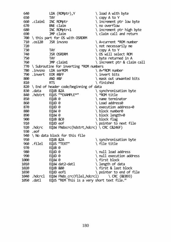
180
640 LDA (ROMptr),Y \ load A with byte 650 TAY \ copy A to Y 660 .claiml INC ROMptr \ increment ptr low byte 670 BNE claim \ no overflow 680 INC ROMptr+1 \ increment ptr high byte 690 JMP claim \ claim call and return 700 \ this part for OS with OSRDRM 710 .os120 JSR invsno \ A=current *ROM number 720 \ not necessarily me 730 TAY \ copy A to Y 740 JSR OSRDRM \ OS will select ROM 750 TAY \ byte returned in A 760 JMP claim1 \ incremnt ptr & claim call 770 \ Subroutine for inverting *ROM numbers 780 .invsno LDA serROM \ A=*ROM number 790 .invert EOR #&FF \ invert bits 800 AND #&F \ mask out unwanted bits 810 RTS \ finished 820 \ End of header code/beginning of data 830 .data EQUB &2A \ synchronisation byte 840 .hdstrt EQUS “*EXAMPLE*” \ *ROM title 850 EQUB 0 \ name terminator 860 EQUD 0 \ Load address0 870 EQUD 0 \ execution address=0 880 EQUW 0 \ block number0 890 EQUW 0 \ block length=0 900 EQUB &C0 \ block flag 910 EQUD eof \ pointer to next file 920 .hdcrc EQUW FNdocrc(hdstrt,hdcrc) \ CRC C&246F) 930 .eof 940 \ No data block for this file 950 EQUB &2A \ synchronisation byte 960 .filel EQUS “TEXT” \ file title 970 EQUB 0 980 EQUD 0 \ null load address 990 EQUD 0 \ null execution address 1000 EQUW 0 \ first block 1010 EQUW dat2—datl \ length of data 1020 EQUB &80 \ first & last block 1030 EQUD eof1 \ pointer to end of file 1040 .hdcrcl EQUW FNdo_crc(filel,hdcrcl) \ CRC (&E893) 1050 .datl EQUS “REM This is a very short text file.”

181
1060 EQUB &D \ The file contents 1070 .dat2 EQUW FNdocrc(datl,dat2)\ Block CRC (&655D) 1080 .eof1 1090 EQUB &2B \ end of ROM marker 1100 .eof 1110 ] 1120 NEXT 1130 PRINT”*S.ROM “;~code%;” “;~O% 1140 END 1150 REM Define function which calculates CRC 1160 REM Requires start and end of block up to 255 bytes 1170 DEF FNdocrc(start,end) 1180 ?&82=(start-&8000+code%) AND &FF 1190 ?&83=(start-&8000+code%.) DIV &100 1200 ?&84=end—start 1210 CALL crc 1220 =(!&80) AND &FFFF 1230 REM Define procedure which assembles CRC routine 1240 DEF PROCassm 1250 startaddr=&82 1260 Lo_crc=&81 1270 Hi_crc=&80 1280 len=&84 1290 FOR I=0 TO 3 STEP3 1300 P%=MC% 1310 [ 1320 OPT I 1330 .crc LDA #0 1340 STA Hi_crc 1350 STA Lo_crc 1360 TAY 1370 .label1 LDA Hi_crc 1380 EOR (startaddr),Y 1390 STA Hi_crc 1400 LDX #8 1410 .label2 LDA Hi_crc 1420 ROL A 1430 BCC label3 1440 LDA Hi_crc 1450 EOR #8 1460 STA Hi_crc 1470 LDA Lo_crc 1480 EOR #&10 1490 STA Lo_crc 1500 .label3 ROL Lo_crc 1510 ROL Hi_crc 1520 DEX 1530 BNE label2
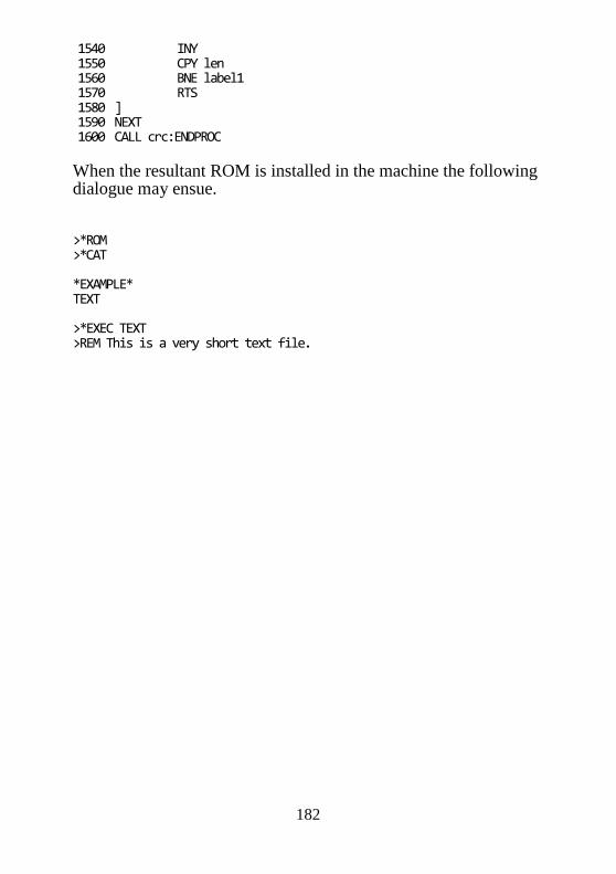
182
1540 INY 1550 CPY len 1560 BNE label1 1570 RTS 1580 ] 1590 NEXT 1600 CALL crc:ENDPROC
When the resultant ROM is installed in the machine the following dialogue may ensue. >*ROM >*CAT *EXAMPLE* TEXT >*EXEC TEXT >REM This is a very short text file.

183
12 Memory allocation and usage Two fundamental points have been stressed in various parts of this book. The first is that programs should only use memory allocated for their general use or memory designated for specific functions when requiring or performing that function. The second point is that software should not make assumptions about its environment. The amount of user RAM available depends on the screen MODE selected and the amount of workspace RAM claimed by paged ROMs. The Electron microcomputer’s memory map:
&FFFF &FF00 Operating system ROM
&FEFF &FE00 Memory mapped I/O – “SHEILA”
&FDFF &FD00 Memory mapped I/O – “JIM”
&FCFF &FC00 Memory mapped I/O – “FRED”
&FBFF &C000 Operating system ROM
&BFFF &8000 Paged ROM space
&7FFF HIMEM Screen memory (variable)
Space for user programs (variable) OSHWM
&E00 Paged ROM workspace/exploded font (variable)
&DFF &D00
NMI routine and paged ROM information (WARNING, not for user programs)
&CFF &A00 Operating system private workspace

184
&9FF &800 Sound system workspace/OS workspace
&7FF &400 Current language private workspace
&3FF &236 Operating system private workspace
&235 &200 OS call indirection vectors
&1FF &100 6502 stack
&FF &00 Zero page
Zero page The zero page on the 6502 is very valuable, as many instructions and addressing modes need to work through page zero. For this reason, areas of zero page are allocated to each of the main memory contenders. Zero page is allocated thus: &00-&8F are allocated to the current language. BASIC reserves locations &70-&8F for the user. &90-&9F are allocated to the Econet system. &A0-&A7 are allocated to the current NMI owner (see section in paged ROMs number 15.3.2). This area is not used on basic cassette machines. It is used extensively by the disc and network filing systems. &A8-&AF are allocated for use by operating system commands during execution. &B0-&BF are allocated as filing system scratch space. but are not exclusively used by the currently active filing system. &C0-&CF are allocated to the currently active filing system. This area is nominally private, and will not be altered unless the filing system is changed, or the absolute workspace is claimed (see paged ROMs chapter 15).
185
&D0-&E1 are allocated to the VDU driver. &D0 is the VDU status as returned by OSBYTE &75. &D1 contains a byte mask for the current graphics point. This byte indicates which bits in the screen memory byte correspond to the point. For example, for the rightmost pixel in a two colour mode, this byte would contain &01, and for a sixteen colour mode, &55. &D2 and &D3 are the text colour bytes to be ORed and EORed into memory, respectively. When writing text to the screen in modes 0 to 6, the pattern byte to be written to the screen is first ORed with the contents of &D2, and then EORed with the contents of &D3. The pattern byte contains a bit set where the pixel is to be the foreground colour, and a bit clear where the pixel is to be the background colour. In four and sixteen colour modes, the pattern byte is expanded before using these locations to take account of the extra bits per pixel. &D4 and &D5 are similar in function to locations &D2 and &D3, only they are the graphics colour bytes. By performing an OR operation, and then an FOR operation, all the GCOL plotting operations can be taken into account by changing the data in these two bytes. The graphics mask at location &D1 is used to mask out the bits in these bytes when they are used. &D6 and &D7 contain the address of the top line of the current graphics character cell (eight bytes long). (See location &31A) &D8 and &D9 contain the address of the top scan line of the current text character. &DA-F are used as temporary workspace. &E0-&E1 unused on the Electron
&E2 is the cassette filing system status byte: bit 0 Set if the input file is open. bit 1 Set if the output file is open. bit 2 Not used.

186
bit 3 Set if currently CATaloguing. bit 4 Not used. bit 5 Not used. bit 6 Set if at end of file. bit 7 Set if end of file warning given.
&E3 is the cassette filing system options byte, as set by the *OPT command. The byte is organised as two nibbles, the top four bits are used for load and save operations, and the bottom four bits are used for sequential access. The format of each nibble is: Bits 0 and 1, the least significant bits of the nibble are used to control what happens after a tape error. When accessing the EXEC file the 'retry' and 'ignore error' options are ignored, so the EXEC is always aborted. These bits have the following meanings (note the higher bit is mentioned first:
00 Ignore errors 10 Retry after an error 01 Abort after an error
Bits 2 and 3, the most significant bits of the nibble are used to control the printing of messages during access. These bits have the following meanings (note the format given is high bit, low bit):
00 No messages 10 Short messages 11 Long messages
&E4-&E6 are used as general operating system workspace. &E7 is the auto repeat countdown timer. This is decremented at 100Hz to zero, at which point the key is re-entered into the buffer. &E8 and &E9 are a pointer to the input buffer into which data is entered by OSWORD &01. &EA is the RS423 timeout counter, which can take the following values:
=1 The cassette filing system is using 6850 =0 The RS423 system holds 6850, but has timed out.
<0 The RS423 system holds 6850, but has not yet timed out.

187
&EB is the 'cassette critical' flag. Bit 7 is set if the cassette filing system is called whilst doing a BGET for EXEC or a BPUT for SPOOL. It is used to ensure that no messages are printed during the access. &EC contains the internal key number of the most recently pressed key, or zero if none is currently pressed. See the table of internal key numbers in Appendix D. &ED contains the internal key number of the first key pressed of those still pressed, or zero if one or no keys are pressed. This is used to implement two key rollover. &EE - 1MHz bus page number &EF contains the accumulator value for the most recent OSBYTE/OSWORD. &F0 contains the X register value for the most recent OSBYTE/OSWORD, or the stack pointer value at the last BRK instruction. &F1 contains the Y register value for the most recent OSBYTE/OSWORD. &F2 and &F3 are used as a text pointer for processing operating system commands and filenames. &F4 - This location contains the ROM number of the currently active paged ROM. (The operating system maintains this as a RAM copy of the paged ROM selection latch.) &F5 to &F7 - These locations are used for the *ROM filing system (see chapter 11). &F8 and &F9 are not used. &FA to &FC - These locations are available for use by routines which have set the interrupt flag. The operating system interrupt routines use these locations but do not expect the contents to remain unchanged between calls. &FC is used as an interrupt accumulator save register. This location is only used temporarily
188
at the very beginning of an interrupt routine while it is setting up the stack. &FD and &FE - These locations are written to after a BRK instruction has been executed. They contain the address of the next byte of memory following the BRK instruction. Thus these locations normally point to an error message (see section 6.2). Upon selection of a language these locations are set to point at the version string of the newly selected language ROM. &FF - This location contains the ESCAPE flag. Bit 7 of this location is set to mark an ESCAPE condition. This flag is cleared when an ESCAPE is serviced. Page 1 This page is used for the 6502 stack. The stack grows from the last byte in this page (&1FF) down towards the bottom of the page. Paged ROM service routines may use the bottom of this page to store error messages. Page 2 Page two is the main work zone of the operating system. It contains all of the main vectors and user accessible operating system variables. Page two is laid out thus: &200-&235 are the vectors. See the vectors chapter 6 and list in Appendix D. &236-&28F are the main system variables, accessed by OSBYTE calls &A6 through &FF. &290-&291 are unused on the Electron &292-&296 and &297-&29B are the two stored values of the system clock, as read by ‘TIME’. Two values are kept, so one can be read while the other is being updated by the interrupt routines. &29C-&2A0 are the countdown interval timer value. This is used

189
to cause an event after a certain time has elapsed. See the chapters on events, number 12, and on OSWORD, number 9, for more details of using the countdown timer. &2A1-&2B0 form the paged ROM type table, as pointed to by value read by OSBYTEs &AA and &AB. Each byte contains the ROM type of the corresponding ROM, or zero if there is no ROM in that socket. For details of ROM types, see the Paged ROMs chapter number 15. &2B1 and &2B2 are the INKEY countdown timer. This is used to time out an INKEY call. &2B6-&2B9 are the low bytes of the most recent analogue converter values. These are in the order channel 1, 2, 3 and 4. &2BA-&2BD are the high bytes of the most recent analogue converter values. &2BE is the analogue system flag. This contains the number of the last channel to finish conversion, or zero if no channels have finished since this value was last read. This byte is read by OSBYTE &80. &2BF-&2C8 are the event enable flags. If zero, the event is disabled, otherwise enabled. See the chapter on events, number 12. &2C9 is the soft key expansion pointer. The next byte to be expanded in a soft key is to be found at &B01+?&2C9 &2CA is the first auto repeat count. This is the next value to go into the auto repeat counter at &E7. This location can be considered a one byte queue for the counter. &2CB-&2CD are used as workspace for two key rollover processing. &2CE is the sound semaphore. If it is zero it means that an envelope interrupt is being processed, so another must be ignored. If it is &FF it means that the envelope software is free.
190
&2CF-&2D7 are buffer busy flags. Bit 7 of these bytes is set if the matching buffer is empty. For a list of buffer numbers see OSBYTE &15 (21). &2D8-&2E0 are the buffer start indices. They contain the offset of the next byte to be removed from each buffer. The offsets are adjusted so that the highest location in the buffer has the offset &FF for all buffers irrespective of size. &2E1-&2E9 are the buffer end indices. They contain the offset of the last byte to be entered into each buffer. If this value is the same as the start offset, the buffer is empty. If this value is less than the start offset, it means the buffer has wrapped around to the start. &2EA and &2EB contain the block size of currently resident block of the open cassette input file. &2EC contains the block flag of the currently resident block of the open cassette input file. (see section 16.10 for the cassette format and details of the flag byte). &2ED contains the last character in currently resident block of the open cassette input file. &2EE-&2FF are used as an area to build OSFILE control blocks for *LOAD and *SAVE Page 3 Page three is used for the VDU workspace, the cassette system workspace and the keyboard buffer. Locations &300-&37F provide the VDU workspace. In examining these locations, it should be noted that there are two forms of graphic co-ordinate, internal and external. The external graphics co-ordinate is exactly that used by the PLOT command in BASIC. The internal graphics co-ordinate is derived from the external by taking into account the graphics origin and scaling so that it is measured in pixels horizontally and vertically. Graphics co-ordinates are stored in four bytes, with the low byte of the X co-ordinate first.

191
VDU workspace is laid out thus: &300-&307 contain the current graphics window in internal co-ordinates.
&300,1 Left hand column in pixels. &302,3 Bottom row in pixels. &304,5 Right hand column in pixels. &306,7 Top row in pixels.
&308-&30B contain the current text window in absolute characters offset from the top left of the screen.
&308 Left hand column. &309 Bottom row. &30A Right hand column. &30B Top row.
&30C-&30F contain the current graphics origin in external co-ordinates. &310-&313 contain the current graphics cursor in external co-ordinates. This is used for calculating relative PLOTs. &314-&317 contain the old graphics cursor in internal co-ordinates. This is used for the generation of triangles. &318 contains the current text cursor X co-ordinate. &319 contains the current text cursor Y co-ordinate. &3lA contains the line within current graphics character of the current graphics point. Because the BBC microcomputer has a non linear address space for the graphics screen, it is simpler to calculate the address of the byte at the top of the character cell that contains a point, and then calculate the row within the character. Thus the location of the byte containing the current graphics point is ?&D6 + 256*?&D7 + &31A. &31B-&31E is used either as graphics workspace or as the first part of the VDU queue.

192
&31F-&323 is the VDU queue. The queue is organised so that whatever the number of characters queued, the last byte queued is always at &323. &324-&327 contain the current graphics cursor in internal co-ordinates. &328-&349 is used as general graphics co-ordinate workspace. &34A and &34B contain the text cursor position as an address. &34C and &34D contain the text window width in bytes, ie. the number of characters wide*the number of horizontal bytes per character*8 for graphics modes. This is used to control the number of bytes which are soft scrolled for each line of scrolling. &34E contains the high byte of the address of the bottom of screen memory. &34F contains the number of bytes of memory taken up by a single character. This is 8 for 2 colour modes, 16 for 4 colour modes, 32 for 16 colour modes. &350 and &351 contain the address of the top left hand corner of the displayed screen. &352 and &353 contain the number of bytes taken per character row of the screen. This is 320 for 8K and 10K modes and 640 for 16K and 20K modes.
&354 contains the high byte of the size of the screen memory in bytes.
&355 contains the current screen mode.
&356 contains the memory map type. The contents indicate the size of the screen memory. It has the value 0 for 20K modes, 1 for the 16K mode, 2 for 10K modes, and 3 for the 8K mode.
&357-&35A contain the current colours. These are stored as the value that would be stored in a byte in screen memory to

193
completely colour that byte to the colour required. The locations are:
&357 Foreground text colour. &358 Background text colour. &359 Foreground graphics colour. &35A Background graphics colour.
&35B and &35C contain the graphics plot mode for the foreground and background plotting respectively. These are set by the GCOL first parameter.
&35D and &35E are used as a general jump vector. The vector is used for decoding VDU control codes and PLOT numbers.
&35F contains a record of the last setting of the cursor start register.
&360 contains the number of logical colours in the current mode minus one.
&361 contains the number of pixels per byte minus one for the current mode, or zero if text only mode. &362 and &363 contain the left and right colour masks, respectively. These bytes contain a bit set in each bit position corresponding to the leftmost or rightmost pixel. For example in a two colour mode, these bytes would contain &80 and &01, and in a sixteen colour mode &AA and &55.
&364 and &365 contain the X and Y co-ordinates of the text input cursor. The input cursor is the position from which characters are COPYed.
&366 not used on the Electron; normally set to 127.
&367 contains the font flag. This byte marks whether or not a particular font zone is being taken from ROM or RAM. If a bit is set it indicates that that zone is in RAM. See OSBYTE &14 (20) for more information on fonts.
bit 7 characters 32-63 (&20-&3F)

194
bit 6 characters 64-95 (&40-&5F) bit 5 characters 96-127 (&60-&7F) bit 4 characters 128-159 (&80-&9F) bit 3 characters 160-191 (&A0-&BF) bit 2 characters 192-223 (&C0-&DF) bit 1 characters 224-255 (&E0-&FF)
&368-&36E are the font location bytes. These contain the upper bytes of the addresses of the fonts for each of the 7 zones mentioned above.
&36F-&37E form the colour palette. One byte is used for each logical colour. That byte contains the physical colour corresponding to the logical colour. The bytes are stored in numerical order of logical colour.
The area of page three from &380 to &3DF is used by the cassette filing system as working storage. &380-&39C is used to store the header block for the BPUT file. See the section on the cassette filing system, number 16.10 for details of header block layout. &39D contains the offset of the next byte to be output into the BPUT buffer.
&39E contains the offset of the next byte to be read from the BGET buffer.
&39F-&3A6 are not used by the Electron OS.
&3A7-&3B1 contain the filename of the file being BGETed.
&3B2-&3D0 contains the block header of the most recent block read: &3B2-&3BD Filename terminated by zero. &3BE-&3C1 Load address of the file. &3C2-&3C5 Execution address of the file. &3C6-&3C7 Block number of the block. &3C8-&3C9 Length of the block. &3CA Block flag byte. &3CB-&3CE Four spare bytes.

195
&3CF-&3D0 Checksum bytes.
&3D1 contains the sequential block gap as set by *OPT 3,n.
&3D2-&3DC contain the filename of the file being searched for. Terminated by zero.
&3DD-&3DE contain the number of the next block expected for BGET.
&3DF contains a copy of the block flags of the last block read. This is used to control newlines whilst printing file information during file searches.
&3E0-&3FF are used as the keyboard input buffer.
It should be noted that although OSBYTE &A0 is officially for reading VDU variables, it may be used to read any of the values in page three.
Pages 4, 5, 6 and 7 These four pages are allocated for the exclusive use of the currently selected language. Should a user be executing code independently of a language this memory may be used by that code. The user’s code should not re-enter a language without ensuring that the language has had an opportunity to reset its workspace. Page 8 This page is allocated for the sound system and for buffers: &800 to &83F general sound workspace, used as follows:
&800-&803 not used &804-&807 sound queue occupancy flag &808-&80B current amplitude &80C-&80F number of amplitude phases processed &810-&813 absolute pitch value &814-&817 number of pitch phases processed &818-&81B number of steps to process

196
&81C-&81F duration &820-&823 interval multiplier &824-&827 envelope number/auto repeat parameter &828-&82B length of remaining note interval &82C-&82F sync hold parameter &830-&833 current pitch setting &834-&837 pitch deviation &838 number of channels required for sync &839 current amplitude step – not used on
Electron &83A target amplitude – not used on Electron &83B number of channels on hold for sync &83C-&83F workspace &83D-&83E frequency parameter as sent to sound
generator &83F not used
&840 to &84F sound channel 0 buffer &850 to &85F sound channel 1 buffer &860 to &86F sound channel 2 buffer &870 to &87F sound channel 3 buffer &880 to &8BF printer buffer &8C0 to &8FF envelope storage area (env. no’s 1-4) On the Electron this area is available for the implementation of external sound and the printer buffer area is used by the Plus 1 expansion software. Locations in this page should only be used by system software performing the appropriate task e.g. user printer routines, sound expansion routines.
Page 9
This page can be used in one of three basic ways:
a) As an extended envelope storage area:
&900-&9BF Envelope storage area, envelopes 5-16. &9C0-&9FF Speech buffer.
b) As an RS423 output buffer:
&900-&9BF RS423 output buffer.

197
&9C0-&9FF Speech buffer.
c) As a cassette output buffer:
&900-&9FF Cassette output buffer.
Uses (b) and (c) are largely compatible apart from speech, as the 6850 can only be used by either the cassette or the RS423 system at any one time, and the cassette system waits until the RS423 output has timed out before taking control of the 6850. At time out, the RS423 output buffer is usually clear. Page &A
This page is used for either the cassette input buffer, or for the RS423 input buffer. Page &B
This page is the soft key buffer. The first seventeen bytes define the start and end locations of the sixteen soft keys. The rest of the page is allocated to the keys themselves. The start offset of soft key string n is held at location &B00+n. The address of the first character of the string is &B0l+?(&B00+n). The address of the last character of the string is &B00+?(&B01+n).
Page &C
This page contains the font for characters 224—255. Each character requires eight sequential bytes. The first byte corresponds to the top line of the character, the second for the line below, etc.
Page &D This page is allocated in the following way: &D00 to &D5F NMI routine &D60 to &D9E reserved &D9F to &DEF paged ROM extended vectors &DF0 to &DFF paged ROM workspace table
198
The NMI routine is the code which is executed when a non-maskable interrupt is generated. This is entered at &D00 and should service the interrupt. The paged ROM extended vectors provide an entry into paged ROM code regardless of which ROM is active as the call is made. See section 10.3 for a description of extended vectors. The paged ROM workspace table contains a single byte page address indicating the start of each ROM’s private workspace (see section 10.3 for further details). WARNING Many games programmers have used page &D. These games will not work when a Plus 1 is fitted because it uses this space. DO NOT continually disconnect and re-connect the Plus 1 because this will damage both the Plus 1 and the Electron. Refer to section 15.7 for a method which will disable the Plus 1. Page &E00 to the OSHWM This memory is available for paged ROM workspace and for character definitions as part of a user defined font. Each ROM is interrogated during a reset to determine its workspace requirements (see paged ROM service calls, section 10.1). This workspace extends from &E00 in page sized units until all the paged ROMs have made their claims. The Acorn BBC range of machines allow the user to define the character patterns that are printed on the screen. The number of user defined characters which may be used depends on the explosion state of the font (see OSBYTE &14). On the Electron and BBC microcomputer the memory required when exploding the font is allocated above the paged ROM workspace. The user (or language) memory starts from the top of this workspace memory and the start address of this memory is called the operating system high water mark (OSHWM).

199
OSHWM to HIMEM This is where a user might expect his program to live. Theoretically this memory has no fixed start address and no fixed end address which taken to extremes means that it may theoretically have no size. In practice, on the BBC microcomputer and the Electron, the region from &2800 to &3000 can be assumed to be within the OSHWM/HIMEM bounds. The language environment may also place constraints on the amount of RAM available for a user’s program and/or data. No RAM should be accessed above HIMEM. This includes the screen memory and, on a second processor, the memory in which the language is stored. Screen memory This memory is not guaranteed to exist at any given place on Acorn BBC range machines, For example when a Tube is active a program may find itself on the second processor and thus any attempts to access what was the screen memory will have no effects on the screen image. For more information about programming practices read chapter 1 on the Acorn design philosophy and programming rules. Paged ROM memory: &8000 to &BFFF This region in the memory map of non-Tube machines or I/O processors contains the currently ‘paged’ paged ROM. When the current filing system is in paged ROM and a filing system function used then the appropriate paged ROM is selected. Operating system ROM memory: &C000 to &FFFF The contents of the OS ROM are undefined except for the OS call entry points described in chapter 2 and the default vector table described in section 6.11.

200
Memory mapped I/O: &FC00 to &FEFF Hardware devices are addressed via these memory locations. Once again extreme care should be taken to address them in the correct manner using OSBYTEs &92 to &97 for reading and writing these addresses. See chapter 14 for more information about the memory mapped I/O. (The OS ROM contains a list of credits in this region made inaccessible by the switch to memory mapped I/O.) The following list shows how Page &FC addresses are allocated for external hardware devices. &FC18 to &FC1F Reserved for use by Acorn &FC28 to &FC2F Reserved for Econet use &FC30 to &FC3F Reserved for use by Acorn &FC60 to &FC6F ACIA &FC70 Analogue to digital converter &FC71 Parallel printer port &FC72 Status register &FC73 ROM scrolling register &FC78 to &FC7F Laser Disc &FC80 to &FC8F Test Hardware &FC90 to &FC9F Sound/Speech &FCB0 to &FCBF VIA &FCC0 to &FCCF Floppy Disc Controller &FCE0 to &FCEF Tube &FCFF Paged RAM register
201
13 An Introduction to Hardware BASIC is a very useful programming tool. It allows users to take advantage of the Electron’s facilities without bothering about the details of how it is performed in hardware. Commands are provided to deal with output to the screen, input from the keyboard and cassette, plus all of the other hardware. The same applies to machine code to a large extent through the use of OSBYTES, OSWORDS and other operating system commands. However, a much more detailed understanding of the hardware and how it can be controlled from machine code programs is very useful and allows certain features to be implemented which would have been impossible in BASIC. The hardware section of this book satisfies the requirements of two types of people. Those who wish to use the hardware features already present on the computer, and those who wish to add their own hardware to the computer. All of the standard hardware features available on the Electron are therefore outlined in detail from a programmer’s point of view. Wherever possible, it is better to use operating system routes for controlling the hardware. These are very powerful and will be referred to whenever relevant. In certain specialised cases, it is necessary to directly access hardware, but even in such cases, OSBYTES &92-&97 should be used. This will ensure that the software will still operate on machines fitted with a Tube processor. For those who wish to add their own hardware, full details on connecting circuits to the Electron’s expansion port are provided. The hardware on the Electron consists of a large quantity of integrated circuits, resistors, capacitors, transistors and various other electronic components. All of these are shown on the full circuit diagram in Appendix F. In order to help those who are not familiar with the general layout of a computer circuit and the devices attached to it, the rest of this introduction is devoted to analysing the hardware as a series of discrete blocks interconnected by a series of system buses.

202
Refer to figure 13.1 whilst reading the following outline of the hardware. There are two major blocks inside the Electron. The first is the uncommitted logic array (usually referred to as the ULA). This is a very large chip which does most of the boring system tasks. It’s life is devoted to copying data from the video memory to the video circuit, driving the cassette, producing sounds, keeping an eye on the keyboard plus other minor tasks. The other major component is the computing centre of the system, called the 6502A central processing unit (CPU). This is the chip which executes all of the programs including BASIC. It is connected to the ULA, ROM and expansion bus. For clarity on the diagram, the connecting buses are all compressed into one which is represented by the double lines terminated with arrows at each major block. A bus is simply a number of electrical links connected in parallel to several devices. Normally one of these devices is talking to another device on the bus. The communication protocols which enable this transfer of data to take place are set up by the control, address and data buses. In the case of the address bus, there are 16 separate lines which allow 65536 (216) different combinations of l’s and 0’s. The maximum amount of directly addressable memory on a 6502 is therefore 65536 bytes. The data bus consists of 8 lines, one for each bit of a byte. Any number between 0 and &FF (255) can be transferred across the data bus. Communication between the ULA, peripherals on the expansion bus, memory and the CPU occurs over the data bus. The CPU can either send out a byte or receive a byte. The data bus is therefore called a bidirectional bus because data flows in any one of two directions. The 6502 address bus is unidirectional because addresses can be provided but not received. The ULA sits back looking at the addresses from the 6502. In order to control the direction of data flow on the data bus, a read or write signal is provided by the control bus. Hardware connected to the system can thereby determine whether it is being sent data or is meant to send data back to the CPU. The other major control bus functions are those of providing a clock, interrupts and resets. The clock signal keeps all of the chips

203
Figure 13.1 - The system block diagram

204
running together at the same rate. The RESET line allows all hardware to be initialised to some predefined state after a reset. An interrupt is a signal sent from a peripheral to the 6502 requesting the 6502 to look at that peripheral. Two forms of interrupt are provided. One of these is the interrupt request (IRQ) which the 6502 can ignore under software control. The other in the non-maskable interrupt (NMI) which can never be ignored. Refer to chapter 7 on interrupts for more information. When power is first applied to the system, a reset is generated by the ULA to ensure that all devices start up in their reset states. The 6502 then starts to get instructions from the ROM. These instructions tell the 6502 what it should do next. A variety of different instructions exist on the 6502. The basic functions available are reading or writing data to memory or an input! output device and performing arithmetic and logical operations on the data. Once the MOS (machine operating system) program is entered, this piece of software gains full control of the system. On an unexpanded Electron, the computer will continue operating under the MOS until it is switched off. Programs are entered into the memory from the keyboard or cassette port, then run. There is some scope for clever programming techniques using the standard hardware - they all involve some tampering with the various registers in the ULA. However, a lot more facilities can be provided by adding extra hardware onto the back of the Electron. Since the Electron is the little brother of the BBC Micro, two forms of expansion are provided for. The first of these covers the addition of hardware which is supplied as standard on a BBC Micro. Within this category are included items like a printer port, analogue to digital converter (for joysticks) and paged ROMs. The second category includes items which would have to be added onto a BBC Micro. Products like the second processors and units which plug onto the One Megahertz Bus are in this category.

205
SHEILA and the ULA On the BBC Micro, all of the resident hardware is mapped into page &FE of memory. This page is called Sheila. The Electron also has all of its internal hardware memory mapped into Sheila, but with one major difference to the BBC Micro. All memory mapped functions are contained within the ULA. These can be summarised as: SHEILA Address Description &FEX0 Interrupt status and control register &FEX2 Video display start address (low byte) &FEX3 Video display start address (high byte) &FEX4 Cassette data register &FEX5 Paged ROM control and interrupt control &FEX6 Counter plus cassette control &FEX7 Controls screen, sound, cassette and CAPS LED &FEX8-XF Palette registers Note that the ULA appears in every 16 byte block of page &FE. Writing to &FE02 is therefore exactly the same as writing to &FEA2 or &FE32 etc.

206
14 Inside the Electron The only hardware inside the Electron which can be accessed directly by the 6502 is the MOS ROM and the ULA, The RAM is read via the ULA, and all internal control functions are performed by the ULA. As has already been mentioned in chapter 13, the ULA is addressed in page &FE (called Sheila). The rest of this chapter explains exactly what all of the registers within the ULA will do, and how they can be of use. Note that there are two ways of communicating with Sheila. OSBYTEs 150 and 151 will read and write to Sheila respectively. Alternatively, the memory mapped addresses can be POKEd directly from programs. 14.1 The ULA and its registers SHEILA &FE00 - Interrupt status and control
Figure 14.1 – IRQ status and control register This register is concerned with the interrupts on the Electron. Interrupts are generated by pieces of hardware which require the 6502 to look at them urgently. A detailed discussion of interrupts can be found in chapter 7.
7 6 5 4 3 2 1 0
MASTER IRQ
POWER ON RESET
DISPLAY END INTERRUPT (AT BOTTOM OF DISPLAYED SCREEN)
REAL TIME CLOCK (50Hzl
TRANSMIT DATA EMPTY
RECEIVE DATA FULL
HIGH TONE DETECT
NOT USED

207
By writing a ‘1’ into the corresponding bits of this register, particular interrupts can be enabled. Writing ‘0’ into a particular bit will disable the related interrupt. Enabled interrupts can get the 6502 to look at them if they generate a suitable signal. Disabled devices will not be looked at even if they generate an interrupt. Note that after an interrupt has occurred, it will be necessary to clear the source of the interrupt, This can be done by writing to address &FE05. SHEILA &FE02 and &FE03 - Screen start address control
Figure 14.2 – The screen start address registers These two registers together form the screen start address. This is the address in memory which will be mapped to the top left-hand corner of the displayed screen. Whenever a line is to be scrolled up or down, this register is incremented or decremented by the number of bytes in a line. As well as allowing vertical scrolling, a limited amount of horizontal scrolling is also possible. The start address can be changed in increments of 64 bytes of memory. In mode 0, 8 bytes are used per character. This means that a scroll in the minimum increment will move the whole screen 8 characters (64/8) left or right.
X X 5 4 3 2 1 0 7 6 5 X X X X X
0 A14A13 A11 A9 A8 A7 A6 X X X X X X

208
The following example demonstrates this feature. Once it has been typed in, the cursor keys can be used to move a block of text about over the mode 0 screen. Note that the actual screen start address has to be shifted right by one bit before it is POKEd into the ULA registers. 10 REM HARDWARE SCROLL EXAMPLE IN MODE 0 20 MODE 0 30 OSBYTE=&FFF4 40 START=&3000 50 PRINT”THIS TEXT CAN SCROLL IN ANY DIRECTION USING CURSOR—KEYS” 60 REM SET KEYS AUTO REPEAT RATE 70 *FX12,3 80 REM SET CURSOR KEYS TO GIVE 136 etc. 90 *FX4,1 100 REPEAT 110 A=INKEY(0) 120 IF A=136 THEN PROCMOVE(64) 130 IF A=137 THEN PROCMOVE(—64) 140 IF A=138 THEN PROCMOVE(—640) 150 IF A=139 THEN PROCMOVE(640) 160 UNTIL FALSE 170 DEF PROCMOVE(offset) 180 START=START+offset 190 REM IF ABOVE SCREEN TOP, SUBTRACT SCREEN LENGTH 200 IF START>=&8000 THEN START=START—&5000 210 REM IF BELOW SCREEN BASE, ADD SCREEN LENGTH 220 IF START<=&3000 THEN START=START+&5000 230 REM CALCULATE HIGH BYTE FOR ULA 240 REM SHIFTED RIGHT BY ONE BIT 250 H% = START DIV 512 260 REM LOW BYTE SHIFTED RIGHT BY ONE BIT 270 L% = (START MOD 512) DIV 2 280 REM NOW PUT INTO ULA REGISTERS 290 REM LOW BYTE TO &FE02 300 A%=151:X%=2:Y%=L% 310 CALL OSBYTE 320 REM HIGH BYTE TO &FE03 330 A%=151:X%=3:Y%=H% 340 CALL OSBYTE 350 ENDPROC

209
SHEILA &FE04 - Cassette data shift register
Figure 14.3a - Reading from the shift register Data is input to the Electron from a cassette recorder, This data shifts into bit 0 of the serial shift register, then into bit 1 and so on until the whole 8 bits of a byte are in the ULA’s receive data register. At this point, data can be read out and stored in memory somewhere. There are several points which are worth remembering when the cassette is used. First of all, a high tone must have been recorded on the tape before any data is read into the Electron. This allows the circuitry to detect that data is about to be sent. The screen mode should have been set to between 4 and 6. If it is not, bits are sometimes lost because the 6502 cannot be interrupted whilst high resolution graphics are being displayed. Finally, the receive data full interrupt should be enabled. This will ensure that the 6S02 knows when a byte can be read. If the byte is not read within about 2ms, the data will be lost forever as bit 7 falls off the end of the register when the next bit comes in!
Figure 14.3b - Writing to the shift register
7 6 5 4 3 2 1 0 DATA IN SERIALLY
READ FROM CASSETTE
BYTE READ OUT IN PARALLEL
7 6 5 4 3 2 1 0DATA OUT SERIALLY
WRITE TO CASSETTE
BYTE WRITTEN IN PARALLEL

210
Writing to this register causes data to be output to the cassette (assuming that the cassette output mode has been set by writing to &FE07). Bit 7 is written out first (so that it is the first in when the tape is played back). When the last bit has been written out, a transmit data empty interrupt is generated. This tells the 6502 that it can put the next byte to be sent into the register. SHEILA &FE05 - Interrupt clear and paging register
Figure 14.4 - The clear interrupt and paging register This register has two purposes, namely the clearing of interrupts and the selection of paged ROMs. Interrupt clearing Putting a ‘1’ into any of the bits 4-7 will cause the associated interrupt to be cleared. Interrupts should be cleared after they have been serviced, but before returning from the interrupt service routine. Bits 4, 5 and 6 are associated with maskable interrupts. Bit 7 is associated with the Non-maskable interrupt, This type of interrupt is generated by very high priority devices like discs. An NMI automatically gives the 6502 precedence over the ULA, even if it is in the middle of displaying a screen. White snow may
NMIHIGHTONE RTC FRAME
END PE P2 P1 P0
ROM PAGING BITS
ROM PAGE ENABLE
CLEAR SCREEN INTERRUPT
CLEAR RTC INTERRUPT
CLEAR HIGH TONE INTERRUPT
NMI CLEAR=1GIVE 6502 PRIORITY OVER ULA - FOR DISCS ETC.

211
therefore occur on the screen when discs are being accessed. Once the 6502 has dealt with the source of interrupt, it should clear it by writing a ‘1’ to bit 7. This gives the screen memory back to the ULA. Paging ROMs The detailed mechanisms for decoding paged ROMs are covered in the next chapter, however, a simple summary is in order here. There is the potential within the operating system to directly address up to 16 paged ROMs of 16K bytes each. However, four of the slots are effectively occupied by the keyboard and the BASIC ROM. The keyboard occupies positions 8 and 9 (both are equivalent). To read from the keyboard, the 14 address lines AO -A13 are used. Each of these is connected to one of the columns of the keyboard. If a particular address line is low, that line of the keyboard is selected on a read. The row data from the keyboard is then returned in the lower 4 bits read from the data bus. The BASIC ROM is selected by paging ROM number 10 or 11. In order to select any of the other ROMs, a particular sequence must be followed, First of all, the ULA must be told that BASIC should be dc-selected. This is done with the page enable bit. One of the ROMs 12-15 will be selected in this way. Now that BASIC has gone, it is (if so desired) possible to page in one of the ROMs 0 to 7. This is simply performed by setting the page enable bit to 0 and selecting the required ROM with bits 0 to 2. You should refer to section 15.4 for a more detailed discussion. SHEILA &FE06 - The counter This write only register has several different functions, depending upon the particular mode of operation.

212
Reading from cassettes
X 0 0 0 0 0 0 0 Figure 14.5a - Cassette receive mode When data is being read from a cassette, this timer is used to count from zero crossings. It therefore effectively determines the cassette baud rate. All bits should be set to 0 (except for bit 7 which doesn’t matter). Cassette receive mode is set by bits 1 and 2 in &FE07. Making sounds
S7 S6 S5 S4 S3 S2 S1 S0 Figure 14.5b - Sound generation mode Sound can only be generated when the cassette is not being used. The 8 bit integer written into this register determines the frequency of all generated sounds. If the value is ‘S’ where ‘S’ is between 0 and 255 in value, the generated sound frequency is given as: Sound frequency = 1 MHz / [16 * (S + 1)] To select sound mode, bits 1 and 2 of &FE07 are used. Frequencies from 244Hz up to 62.5kHz can be generated, but you won’t be able to hear the really high frequencies!

213
Writing to cassettes
X X X X X X X X Figure 14.5c - Writing to cassette The states of the bits written to this register are ignored in this mode. The counter is used to control the received data baud rate, but cannot be changed. Bits 1 and 2 of &FE07 should be used to select the cassette output mode. SHEILA &FE07 - Miscellaneous control
Figure 14.6 - control register This general purpose control register provides a selection of different functions.
2 1 X
D2 D1 MODE
0 0 CASSETTE INPUT0 1 SOUND
GENERATION1 1 CASSETTE OUTPUT1 1 NOT USED
ROM PAGE ENABLE
CLEAR SCREEN INTERRUPT
CLEAR RTC INTERRUPT
CLEAR HIGH TONE INTERRUPT
NMI CLEAR=1GIVE 6502 PRIORITY OVER ULA - FOR DISCS ETC.
34567
214
Communications mode, bit 1 and 2 Bits 1 and 2 control whether data is being written to a cassette recorder, read from a cassette recorder, or generating sounds. These three functions are mutually exclusive, so it is not possible to play cheery tunes whilst waiting for a long program to load. Display mode selection, bits 3, 4 and 5 There are seven display modes available on the Electron. These can be selected by writing a number between 0 and 6 into bits 5, 4, 3. Note that the other possible mode (7) is only available on the BBC Micro. Cassette motor control, bit 6 Setting this bit to ‘1’ will turn the cassette motor on. Setting it to ‘0’ will turn the motor off. Motor control is effected by a small relay contact inside the Electron. It is possible to use this to switch small battery operated equipment on and off (for example a transistor radio). CAPS LOCK LED control, bit 7 Setting this bit to a ‘1’ turns on the CAPS LOCK LED on the side of the keyboard. A ‘0’ turns it off again. SHEILA &FE08 to &FE0F - the colour palette These addresses in the ULA define the mapping between the logical colours which are provided by programs and the physical colours which are displayed on the screen. For example, in the two colour mode, logical colour 1 will actually produce a colour defined by &FE08 bit 6 (blue), &FE08 bit 2 (green) and &FE09 bit 2 (red). The bits are negative logic, which means that a ‘1’ in bit 6 of &FE08 will ensure that blue is turned off for colour 1. The cursor and flashing colours are entirely generated in software: This means that all of the logical to physical colour map must be changed to cause colours to flash.

215
D7 D6 D5 D4 D3 D2 D1 D0 &FE08 X B1 X B0 X G1 X X
&FE09 X X X G0 X R1 X R0 Figure 14.7a – 2 colour mode palette
Figure 14.7b - 4 colour mode palette
}Colours 0,2,8,10
}Colours 4,6,12,14
}Colours 5,7,13,15
}Colours 1,3,9,11
Figure 14.7c - 16 colour mode palette
D7 D6 D5 D4 D3 D2 D1 D0 &FE08 B3 B2 B1 B0 G3 G2 X X
&FE09 X X G1 G0 R3 R2 R1 R0
D7 D6 D5 D4 D3 D2 D1 D0
&FE08 B10 B8 B2 B0 G10 G8 X X
&FE09 X X G2 G0 R10 R8 R2 R0
D7 D6 D5 D4 D3 D2 D1 D0
&FE08 B14 B12 B6 B4 G14 G12 X X
&FE09 X X G6 G4 R14 R12 R6 R4
D7 D6 D5 D4 D3 D2 D1 D0
&FE08 B15 B13 B7 B5 G15 G13 X X
&FE09 X X G7 G5 R15 R13 R7 R5
D7 D6 D5 D4 D3 D2 D1 D0
&FE08 B11 B9 B3 B1 G11 G9 X X
&FE09 X X G3 G1 R11 R9 R3 R1
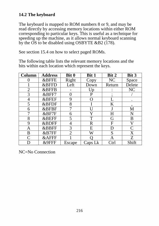
216
14.2 The keyboard The keyboard is mapped to ROM numbers 8 or 9, and may be read directly by accessing memory locations within either ROM corresponding to particular keys. This is useful as a technique for speeding up the machine, as it allows normal keyboard scanning by the OS to be disabled using OSBYTE &B2 (178). See section 15.4 on how to select paged ROMs. The following table lists the relevant memory locations and the bits within each location which represent the keys. Column Address Bit 0 Bit 1 Bit 2 Bit 3
0 &BFFE Right Copy NC Space 1 &BFFD Left Down Return Delete 2 &BFFB - Up : NC 3 &BFF7 0 P ; / 4 &BFEF 9 O L . 5 &BFDF 8 I K , 6 &BFBF 7 U J M 7 &BF7F 6 Y H N 8 &BEFF 5 T G B 9 &BDFF 4 R F V A &BBFF 3 E D C B &B7FF 2 W S X C &AFFF 1 Q A Z D &9FFF Escape Caps Lk Ctrl Shift
NC=No Connection

217
15 Outside the Electron 15.1 Introduction to expanding the Electron This chapter is intended for those who want to add their own bits of hardware onto the Electron. There are several reasons for doing this. The most common one is to allow the Electron to access facilities provided for the BBC Micro. All of the common interfaces such as discs, printer port, analogue to digital converter, speech chip, paged ROMs etc. can easily be added onto the Electron. If care is taken with the design, these products will operate in an almost identical manner to those on the BBC Micro. Several interface add-ons can already be purchased from Acorn. If the only point in adding hardware onto the Electron were to make it totally BBC Micro compatible, there would have been little point in buying the Electron in the first place. In fact, the Electron has more potential for expansion than a BBC Micro. Why? Because all necessary system buses come out on the expansion connector. This ability to access all of the buses means that the devices which can be added onto the Electron are limited only by the imagination (and maximum allowable loading of the buses). Appendix G provides a summary of the expansion devices available for the Electron, grouped by generic type. 15.2 The Expansion Connector All required signals from the Electron are present on this connector. In order to make use of them, a basic knowledge of interfacing to the 6502 will be required. Such a knowledge can be acquired by reading some of the popular electronics magazines and specialised books on interfacing. The aim in this book is to explain all of the details to those who have already read enough about microcomputer hardware in general, and now want to know about the Electron in particular.
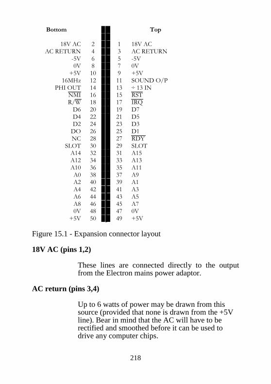
218
Bottom Top
18V AC 2 1 18V AC
AC RETURN 4 3 AC RETURN -5V 6 5 -5V 0V 8 7 0V +5V 10 9 +5V
16MHz 12 11 SOUND O/P PHI OUT 14 13 ÷ 13 IN
NMI 16 15 RST R/W 18 17 IRQ D6 20 19 D7 D4 22 21 D5 D2 24 23 D3 DO 26 25 D1 NC 28 27 RDY
SLOT 30 29 SLOT A14 32 31 A15 A12 34 33 A13 A10 36 35 A11 A0 38 37 A9 A2 40 39 A1 A4 42 41 A3 A6 44 43 A5 A8 46 45 A7 0V 48 47 0V +5V 50 49 +5V
Figure 15.1 - Expansion connector layout 18V AC (pins 1,2)
These lines are connected directly to the output from the Electron mains power adaptor.
AC return (pins 3,4)
Up to 6 watts of power may be drawn from this source (provided that none is drawn from the +5V line). Bear in mind that the AC will have to be rectified and smoothed before it can be used to drive any computer chips.

219
-5V pins (5,6)
This is a -5 volt supply from the Electron, from which a maximum of 20mA can be drawn. It would often be used to power RS423 expansions.
0V (pins 7, 8, 47, 48)
This is the signal and power ground on the Electron. All external circuits must have their 0 volt lines connected to this point.
+5V (pins 9,10,49,50)
This is a +5 volt power supply from the Electron. A maximum of 500mA can be drawn from it, but note that no power can be taken from the 18V AC line if this is done.
Sound o/p (pin 11)
Sound output from the Electron ULA. This signal is 3 volts peak to peak fed via a 1K series resistor.
16MHz (pin 12)
This is the master 16MHz clock from the Electron main oscillator. It can be used for clock generation on expansion modules, but see section 15.3.3 for a description of clock synchronisation.
16/13 MHz (pin 13)
This is 16MHz divided by 13. It is normally used for baud rate generation, and will give approximately 1200Hz if divided by 1024.

220
PHI out (pin 14)
This is a nominally 2 MHz clock as connected to the 6502A. The low time is some 250ns. The high time varies depending upon the operation being performed. It is 250ns when reading ROMs, 750ns or 1250ns when accessing the 1MHz bus (depending upon the relative phase of the 2MHz clock) and can be up to 40µs due to screen access in modes 0 to 3. The clock timing is covered in greater depth in section 15.3. Note that the NMI must be synchronised with PHI out. This is because the NMIs give the 6502 precedence over the ULA for the RAM. Incorrect data may be read from the RAM if the NMI is not latched on a negative going edge of PHI out.
RST (pin 15)
Active low reset signal. This is an OUTPUT ONLY for resetting expansion modules on power up, or when the BREAK key is pressed.
NMI (pin 16)
Non-maskable Interrupt (negative edge triggered). This open collector (wire-OR) line is the system NMI and can be asserted by an expansion module pulling it low. There is a 3K3 pull-up resistor inside the ULA. You must be very careful to avoid holding this line low after the interrupt has been serviced, because it will mask other interrupts whilst asserted. For more details about NMIs, you should refer to chapter 7.
IRQ (pin 17)
This is the active-low IRQ (interrupt request). It is an open collector (wire-OR) line, so it can be asserted by any expansion module pulling it low. There is a 3K3 pull-up resistor within the ULA. Note that interrupts MUST NOT occur until the

221
software in the machine has initialised to a state at which it can deal with them. Power up and reset conditions should therefore disable all IRQs, It is important to ensure that not too much of the interrupt service time is used up, otherwise some operations like the system clock may cease to function correctly.
R/W (pin 18)
This is the system read/write line from the 6502. It tells peripheral devices whether the 6502 is sending data to them, or is expecting data from them.
D0-D7 (pins 19 to 26)
This is the 8 bit wide bi-directional data bus. All data is transferred over this bus, the direction of data transfer being determined by the state of the read/write line.
RDY (pin 27)
This is the active low ready line from the 6502. It can be asserted by an expansion to slow down the processor when it is reading slow memory. This line is only operational on reads.
(pin 28)
No connection. (pins 29,30)
Polarising key connector to ensure that boards cannot be plugged in the wrong way round.
A0-A15 (pins 31 to 46)
This is the system address bus. There are 16 lines in this bus which allow 216 (65536) different locations to be addressed.
222
15.3 Designing Circuits It might at first appear to be very easy to add anything onto the Electron Expansion Bus. There is however one fairly major problem. The 6502A often changes speed to cope with the accessing of different devices. These fall into two main categories. 15.3.1 Accessing the ROM When the ROM is being accessed, the 6502 runs at the maximum possible speed of 2MHz; PHI OUT is low for 250ns and then high for 250ns. 15.3.2 Accessing the RAM and peripherals When RAM or peripheral devices are accessed, the timing will be highly dependent on the display mode. This is because twice as much data has to be removed from the RAM to produce the display in modes 0-3 as in modes 4-6. Modes 4-6 The processor will normally be running at 2MHz when it first needs to access RAM or peripherals like the 6522. It has to slow down to 1MHz first. This slow down either consists of a PHI OUT low time of 250ns followed by a high time of 750ns, or a low of 250ns followed by a high of 1250ns. The particular type of transition which occurs will depend upon the relative phases of the 2MHz and 1MHz clocks, This is illustrated in figure 15.1. Both the 1MHz and 2MHz clocks are internal to the ULA, and are not available outside. They must be generated separately (see later in this section). Modes 0-3 In these modes, the ULA must have access to the RAM for all the displayed part of a line (40us out of 64µs in 256 lines out of 312). This doesn’t matter provided that the CPU only wants to access peripherals and the ROM, which it is free to do in the normal way. However, if it tries to access RAM the ULA will hold it’s clock high for up to 40µs. The overall effect is that the

223
processor can be effectively disabled for up to 40µs. The only way for the processor to obtain priority over the ULA is by an NMI being generated. This will automatically cause the ULA to release the 6502 (and the RAM), but inevitably creates snow on the screen. 15.3.3 Generating the 1MHz clock Since the 1MHz and 2MHz signals only exist inside the ULA, it is necessary to regenerate them outside. Two clocks are provided on the expansion connector. A 16MHz one and a 16/13MHz one for baud rate generation. The former of these can be used to generate a 1MHz clock, This has to be synchronised to the processor clock if it is to be used with peripherals like the 6522 VIA. A simple division by 16 will not produce a suitable clock signal. The circuit in figure 15.2a will produce a suitable in phase signal. The timing for this is shown in figure 15.2b. 15.3.4 Long delays for interrupts It is important to bear in mind how long the delays might be before a particular requested interrupt is serviced, This is determined by the longest period for which interrupts can be disabled. In modes 0-3, this delay can be up to 100ns in the very worst case. Such a long delay can cause problems with unbuffered circuits like the cassette serialiser/deserialiser. The only solution is to ensure that such devices are only used from modes 4-6 (even if it means forcing a particular mode before executing a routine). The interrupt delay is only 4ms at worst in modes 4-6, so most actions which require a fast response can be executed in one of these modes. Note that NMIs can always be used as a last resort where necessary, but are normally reserved for disc and Econet accesses.

224
Figure 15.2a - A 16MHz to 1MHz synchronisation circuit Figure 15.2b - the timing applied to figure 15.2a

225
15.4 Sideways ROMs Sideways ROMs can be selected in place of BASIC. Languages like LISP, disc filing systems, utilities etc can all be plugged in. These sideways ROMs are covered from a software point of view in chapters 8 to 11. From a hardware point of view, up to 16 sideways ROMs are allowed. However, four of these are already allocated on the standard Electron. BASIC occupies two slots (ROMs 10 and 11 it appears the same in each). The keyboard occupies slots 8 and 9. The remaining 12 ROM slots are all available for expansion. The ROM paging register is located in the ULA, and can be accessed by writing to location &FE05 (see section 14). There are two distinct ways of accessing ROMs via this register. The first method accesses ROMs 12 to 15. This operation is very simply performed by writing the required ROM number into the low nibble of &FE05. Hence: D7 D6 D5 D4 D3 D2 D1 D0 Write at &FE05 0 0 0 0 1 1 R1 R0 where R1 and R0 control which ROM is selected. Suitable hardware must be included in the expansion unit to cope with this method of selecting ROMs. Selection of one of the ROMs 12 to 15 can be carried out by the following code. Be careful to ensure that the write to &F4 always occurs before the write to &FE05, just in case an interrupt occurs in between. LDA #ROMnumber STA &F4 STA &FE05
The second method for accessing ROMs will allow those numbered 0 to 7 to be selected. It is not possible to select these ROMs directly, because BASIC will still be paged in. The only way of paging BASIC and the keyboard out is to select one of the ROMs 12 to 15 first. This access causes the internal ROMs to page out. The correct ROM selection code can then be sent to the lower three bits of &FE05.

226
D7 D6 D5 D4 D3 D2 D1 D0 Write at &FE05 0 0 0 0 0 R2 R1 R0 where R2, R1 and R0 select the required ROM. As with the other ROM slots, new hardware must be provided at address &FE05 to select the relevant ROMs. Code to select a ROM numbered 0 to 7 could be: LDA #&0C \to deselect BASIC STA &F4 \one of ROM 12 to 15 STA &FE05 \must be selected LDA #ROMnumber \Now select desired STA &F4 \Low order ROM STA &FE05
It is essential that the A register is stored to &F4 before &FE05 in case an interrupt occurs in between. When the machine is powered up, the sideways ROMs are polled in order from 15 down too. The first one which is found to be a language ROM (see the Paged ROM firmware section for specification) will start executing. Since BASIC is in slot 10/11, a ROM which is required to power-up before BASIC must be in one of the sockets 12 to 15. The ROMs 12 to 15 are allocated to high priority NMI devices or languages which are expected to power up before BASIC. The reason for putting high priority NMI servicing ROMs in these sockets is that a smaller delay is required to page them in than for ROMs 0 to 7. The lower priority ROMs are all selected by performing two writes to the paging register. The first is to deselect BASIC, the second is to select the required ROM.

227
The Acorn Plus 1 expansion unit forces the priority of ROMs to be (from highest down):
ROMs 15 to 12 ROMs 7 to 0 BASIC
This implies that any language which is fitted to the Plus 1 will automatically power up ahead of BASIC. ROM allocation has been defined by Acorn as follows: ROM USE 0,1 Second external socket on expansion module (SK2) 2,3 First external socket on the expansion module (SK1) 4 Disc 5,6 USER applications 7 Modem interface ROM 8,9 Keyboard 10,11 BASIC 12 Expansion module operating system 13 High priority slot in expansion module 14 ECONET 15 Reserved 15.5 The One Megahertz Bus Most 6502 compatible peripherals will generally be connected onto the 1MHz regenerated bus. This allows relatively slow devices to be accessed. On the BBC Micro, page &FC has been allocated especially for 1MHz devices, This page is called FRED. Generally, devices resident within FRED have relatively small memory requirements (mainly control and data registers). Since Electron expansion should be compatible with BBC Micro expansion (so they can use the same expansion peripherals), the allocation of devices in FRED has been very well defined. The following list includes items which would normally be resident in Sheila on the BBC Micro, but which have to go on the 1MHz bus on an Electron.

228
&FC00 to &FC0F Test hardware &FC10 to &FC13 TELETEXT &FC14 to &FC1F PRESTEL &FC20 to &FC27 IEEE 488 interface &FC28 to &FC2F ECONET &FC30 to &FC3F CAMBRIDGE RING interface &FC40 to &FC47 WINCHESTER DISC interface &FC48 to &FC5F Reserved for Acorn expansions &FC60 to &FC6F 6850 ACIA &FC70 A to D converter &FC71 CENTRONICS parallel interface &FC72 Status register
BSY ADC FB2 FB1 X X X X Where BSY = printer busy ADC = A to D conversion end FB1 = Fire button 1 FB2 = Fire button 2 X= undefined
&FC73 to &FC7F Reserved for Acorn expansions &FC80 to &FC8F Test hardware &FC90 to &FC9F Sound and speech &FCA0 to &FCAF Reserved for Acorn expansions &FCB0 to &FCBF 6522 VIA/Real time clock &FCC0 to &FCCF Floppy disc controller &FCD0 to &FCDF USER applications &FCE0 to &FCEF The TUBE &FCF0 to &FCFE USER applications &FCFF Paging register for JIM Note that page &FD in the Electron address space is used in conjunction with the paging register in FRED to provide an extra 64K of memory. This memory is accessed one page at a time. The particular page being accessed is selected by the value in FRED’s paging register, and is referred to as the extended page number. Accessing memory via the 1MHz bus in this way will generally be about 20 times slower than accessing memory directly.

229
15.6 The Analogue to Digital converter The A to D converter is present at location &FC70 with some status bits in &FC72. To obtain a value from the converter, it is first necessary to poke a number representing a channel number into &FC70, according to the following table:
Channel Value 1 4 2 5 3 6 4 7
The result will then appear in &FC70 when bit 6 of &FC72 goes low. &FC72 also contains the status of the two fire buttons in bits 4 and 5. 15.7 Disabling the Plus 1 To completely disable the Plus 1, the following calls are required: *FX163,128,1
?&212=&D6
?&213=&F1
?&2AC=0
The first call disables ADC conversion. The second and third calls redirect FILEV to its default location and the fourth call disables the Expansion ROM by clearing the associated byte in the ROM table.
230
Appendix A - VDU Code Summary This Appendix describes the functions performed by the whole of the character set when printed using VDU or PRINT CHR$. Note that several ones are labelled expansion. This means that they will only be effective if the associated expansion modules are connected. Dec hex CTRL + bytes function 0 0 @ 0 Does nothing 1 1 A 1 Send character to printer (expansion) 2 2 B 0 Enable printer (expansion) 3 3 C 0 Disable printer (expansion) 4 4 D 0 Write text at text cursor 5 5 E 0 Write text at graphics cursor 6 6 F 0 Enable VDU drivers 7 7 G 0 Make a short bleep (BEL) 8 8 H 0 Move cursor back one character 9 9 1 0 Move cursor forward one character 10 A J 0 Move cursor down one line 11 B K 0 Move cursor up one line 12 C L 0 Clear text area 13 D M 0 Carriage return 14 E N 0 Paged mode on 15 F O 0 Paged mode off 16 10 P 0 Clear graphics area 17 11 Q 1 Define text colour 18 12 R 2 Define graphics colour 19 13 S 5 Define logical colour 20 14 T 0 Restore default logical colours 21 15 U 0 Disable VDU drivers/delete current line 22 16 V 1 Select screen MODE 23 17 W 9 Re-program display character 24 18 X 8 Define graphics window 25 19 Y 5 PLOT K,X,Y 26 1A Z 0 Restore default windows 27 1B [ 0 Reserved 28 1C \ 4 Define text window

231
29 1D ] 4 Define graphics origin 30 1E ^ 0 Home text cursor to top left of window 31 1F _ 2 Move text cursor to X, Y 32-126 Complete set of ASCII characters 127 7F DEL 0 Backspace and delete 128-223 Normally undefined (define using *FX20) 224-255 User defined characters

232
Appendix B PLOT numbers 0 Move relative to last point 1 Draw relative to last point in current foreground colour 2 Draw relative to last point in logical inverse colour 3 Draw relative to last point in current background colour 4 Move absolute 5 Draw absolute in current foreground colour 6 Draw absolute in logical inverse colour 7 Draw absolute in current background colour Higher PLOT numbers have other effects which are related to the effects given by the values above. 8-15 Last point in line omitted when ‘inverted’ plotting used 16-23 Using a dotted line 24-31 Dotted line, omitting last point 32-63 Reserved for Graphics Extension ROM 64-71 Single point plotting 72-79 Horizontal line filling 80-87 Plot and fill triangle 88-95 Horizontal line blanking (right only) 96-255 Reserved for future expansions

233
Horizontal line filling These PLOT numbers start from the specified X,Y co-ordinates. The graphics cursor is then moved left until the first non-background pixel is encountered. The graphics cursor is then moved right until the first non-background coloured pixel is encountered on the right hand side. If the PLOT number is 73 or 77 then a line will be drawn between these two points in the current foreground colour. If the PLOT number is 72 or 76 then no line is drawn but the cursor movements are made (these may be read using OSWORD call with A=&D/13, see chapter 4). Horizontal line blanking right These PLOT numbers can be used to undraw an object on the screen. They have an the opposite effect to those of the horizontal line filling functions except that the graphics cursor is moved right only. PLOT numbers 91 and 95 will cause a line to be drawn from the specified co-ordinates to the nearest background coloured pixel to the right in the background colour. PLOT numbers 89 and 93 move the graphics cursor but do not cause the line to be blanked.

234
Appendix C ———— Screen mode layouts MODE 0 Screen layout Graphics 640x256 Colours 2 Text 80x32 &3000 &3008 &3278 &3001 &3009 &3279 &3002 &300A &327A &3003 &300B &327B &3004 &300C &327C &3005 &300D &327D &3006 &300E &327E &3007 &300F &327F &3280 &3281
&7B06 &7B07 &7D80 &7D88 &7FF8 &7D81 &7D89 &7FF9 &7D82 &7D8A &7FFA &7D83 &7D8B &7FFB &7D84 &7D8C &7FFC &7D85 &7D8D &7FFD &7D86 &7D8E &7FFE &7D87 &7D8F &7FFF
8 PIXELS 1BIT/PIXEL
Note that the screen layout is only as shown after a CLS and will change as the screen is scrolled.
7 6 5 4 3 2 1 0

235
MODE 1 Screen layout Graphics 320x256 Colours 4 Text 40x32 &3000 &3008 &3278 &3001 &3009 &3279 &3002 &300A &327A &3003 &300B &327B &3004 &300C &327C &3005 &300D &327D &3006 &300E &327E &3007 &300F &327F &3280 &3281
&7B06 &7B07 &7D80 &7D88 &7FF8 &7D81 &7D89 &7FF9 &7D82 &7D8A &7FFA &7D83 &7D8B &7FFB &7D84 &7D8C &7FFC &7D85 &7D8D &7FFD &7D86 &7D8E &7FFE &7D87 &7D8F &7FFF
4 PIXELS 2BITS/PIXEL
Note that the screen layout is only as shown after a CLS and will change as the screen is scrolled.
7 6 5 4 3 2 1 0

236
MODE 2 Screen layout Graphics 160x256 Colours 16 Text 20x32 &3000 &3008 &3278 &3001 &3009 &3279 &3002 &300A &327A &3003 &300B &327B &3004 &300C &327C &3005 &300D &327D &3006 &300E &327E &3007 &300F &327F &3280 &3281
&7B06 &7B07 &7D80 &7D88 &7FF8 &7D81 &7D89 &7FF9 &7D82 &7D8A &7FFA &7D83 &7D8B &7FFB &7D84 &7D8C &7FFC &7D85 &7D8D &7FFD &7D86 &7D8E &7FFE &7D87 &7D8F &7FFF
2 PIXELS 4BITS/PIXEL
Note that the screen layout is only as shown after a CLS and will change as the screen is scrolled.
7 6 5 4 3 2 1 0

237
MODE 3 Screen layout Graphics Not available Colours 2 Text 80x25 &4000 &4008 &4278 &4001 &4009 &4279 &4002 &400A &427A &4003 &400B &427B &4004 &400C &427C &4005 &400D &427D &4006 &400E &427E &4007 &400F &427F BLANK BLANK BLANK BLANK BLANK BLANK &4280 &4281
&7980 BLANK BLANK &7C00 &7C08 &7E38 &7C01 &7C09 &7E39 &7C02 &7C0A &7E3A &7C03 &7C0B &7E3B &7C04 &7C0C &7E3C &7C05 &7C0D &7E3D &7C06 &7C0E &7E3E &7C07 &7C0F &7E3F BLANK BLANK BLANK BLANK BLANK BLANK
8 PIXELS 1BIT/PIXEL
Note that the screen layout is only as shown after a CLS and will change as the screen is scrolled.
7 6 5 4 3 2 1 0

238
MODE 4 Screen layout Graphics 320x256 Colours 2 Text 40x32 &5800 &5808 &5938 &5801 &5809 &5939 &5802 &580A &593A &5803 &580B &593B &5804 &580C &593C &5805 &580D &593D &5806 &580E &593E &5807 &580F &593F &5940 &5941
&7D86 &7D87 &7EC0 &7EC8 &7FF8 &7EC1 &7EC9 &7FF9 &7EC2 &7ECA &7FFA &7EC3 &7ECB &7FFB &7EC4 &7ECC &7FFC &7EC5 &7ECD &7FFD &7EC6 &7ECE &7FFE &7EC7 &7ECF &7FFF
8 PIXELS 2BITS/PIXEL
Note that the screen layout is only as shown after a CLS and will change as the screen is scrolled.
7 6 5 4 3 2 1 0

239
MODE 5 Screen layout Graphics 160x256 Colours 4 Text 20x32 &5800 &5808 &5938 &5801 &5809 &5939 &5802 &580A &593A &5803 &580B &593B &5804 &580C &593C &5805 &580D &593D &5806 &580E &593E &5807 &580F &593F &5940 &5941
&7D86 &7D87 &7EC0 &7EC8 &7FF8 &7EC1 &7EC9 &7FF9 &7EC2 &7ECA &7FFA &7EC3 &7ECB &7FFB &7EC4 &7ECC &7FFC &7EC5 &7ECD &7FFD &7EC6 &7ECE &7FFE &7EC7 &7ECF &7FFF
4 PIXELS 2BITS/PIXEL
Note that the screen layout is only a s shown after a CLS and will change as the screen is scrolled.
7 6 5 4 3 2 1 0

240
MODE 6 Screen layout Graphics Not available Colours 2 Text 40x25 &6000 &6008 &6138 &6001 &6009 &6139 &6002 &600A &613A &6003 &600B &613B &6004 &600C &613C &6005 &600D &613D &6006 &600E &613E &6007 &600F &613F BLANK BLANK BLANK BLANK BLANK BLANK &6140
&7CC7 BLANK BLANK &7F00 &7F08 &7F38 &7F01 &7F09 &7F39 &7F02 &7F0A &7F3A &7F03 &7F0B &7F3B &7F04 &7F0C &7F3C &7F05 &7F0D &7F3D &7F06 &7F0E &7F3E &7F07 &7F0F &7F3F BLANK BLANK BLANK BLANK BLANK BLANK
8 PIXELS 1BIT/PIXEL
Note that the screen layout is only as shown after a CLS and will change as the screen is scrolled.
7 6 5 4 3 2 1 0

241
Appendix D - Operating System Calls and Vectors Routine Vector Function Addr Name Addr Name USERV 200 The user vector BRKV 202 The BRK vector IRO1V 204 Primary interrupt
vector IRQ2V 206 Unrecognised IRQ
vector OSCLI FFF7 CLIV 208 Command line
interpreter OSBYTE FFF4 BYTEV 20A *FX/OSBYTE call OSWORD FFF1 WORDV 20C OSWORD call OSWRCH FFEE WRCHV 20E Write character OSNEWL FFE7 - - Write LF, CR to
screen OSASCI FFE3 - - Write character, OSRDCH FFE0 &0D=LF, CR OSFILE FFDD RDCHV 210 Read character OSARGS FFDA FILEV 212 Load/save file OSBGET FFD7 ARGSV 214 Load/save file data OSBPUT FFD4 BGETV 216 Get byte from file OSGBPB FFD1 BPUTV 218 Put byte in file OSFIND FFCE GBPBV 21A Multiple
BPUT/BGET EVNTV 220 Event vector UPTV 222 User print routine NETV 224 Econet vector VDUV 226 Unrecognised VDU
commands KEYV 228 Keyboard vector INSV 22A Insert into buffer
vector REMV 22C Remove from buffer
vector CNPV 22E Count/purge buffer
vector

242
IND1V 230 Spare vector IND2V 232 IND3V 234 NVRDCH FFCB Non-vectored read
char. NVWRCH FFC8 Non-vectored write
char. GSREAD FFC5 Read char. from
string GSINIT FFC2 String input initialize OSEVEN FFBF Generate an event OSRDRM FFB9 Read byte in paged
ROM

243
Appendix E ---- Plus 1 ROM slot
Figure E.1 - The Plus 1 ROM slot connector The cartridge interface is an earlier and simpler version of that later used on the BBC Master. Signals which differ between the two machines are shown with an asterisk in the diagram. The description below explains the function of all the signals and the differences between machines. Note that most of the standard BBC Micro 1MHz bus signals are available from this slot. However, some of the uses are marginally different to the BBC 1MHz bus. A full specification for producing suitable add-ons is available from Acorn Computers Limited. SIDE 'A' 1 +5V - Power supply This is the system logic supply rail. No more than 150mA should be drawn by a cartridge in a fully configured Master 128 computer, ie with internal co-processor fitted. No more than 50mA should be drawn by a cartridge fitted to the Electron. 2 n0E - Output Enable : Input with CMOS levels This is an active low signal during the PH12 period of the system clock. It is intended to switch on the output buffers of memory devices in cartridges. It is not guaranteed to be high at other times.

244
3 nRST - System Reset : Input with CMOS levels This signal is active low during system reset. It is not synchronised to any internal clock. 4 CSRW - Chip Select / Read/Write : Input with CMOS levels On the Electron: This pin is the CPU read/write line. On the Master 128: This pin changes function according to the memory region that the CPU is addressing. During accesses to devices in the region &FC00 to &FEFF it is equivalent to the CPU read/write line during nPH12. For all other accesses it is an active high chip select for memory devices. It is not guaranteed to be low at other times. This approach is necessary for compatibility with the Electron. 5 A8 - Address line 8 : Input with TTL levels 6 A13 - Address line 13 : Input with TTL levels 7 A12 - Address line 12 : Input with TTL levels 8 PH12 - CPU clock : Input with CMOS levels This input is the host computer PH12out. 9 -5V - The negative supply voltage No more than 20mA per cartridge should be drawn from this supply. 10 CSYNC/MADET On the Electron: This is a "no connect" on the Electron. On the Master 128: This pin has two functions dependant on the position of a link in the host computer: E/nB: this is the default function. It allows hardware in cartridges to "know" which into which type of computer it is plugged. It is a

245
direct connection to +0V in the Master 128 and a floating node in the Electron. CSYNC - Composite Synchronisation: Input with TTL levels The system composite vertical and horizontal synchronisation is made available. It is intended to be used in genlock applications. 11 RNW/READY This has different functions on the Electron and the Master 128. On the Electron: READY - CPU wait state control : Open collector output When driven low, this line will cause the CPU to extend its cycle until READY is released. This will only work on Electrons with CMOS CPUs. With NMOS CPUs it will only work on read cycles. On the Master 128: R/W - Data Direction Control : Input with TTL levels This is the system data buffer direction control. If low, cartridges are being written to; if high and selected they may drive the bus during PH12. 12 nNMI - Non maskable interrupt : Open collector output This signal is connected to the system NMI line. It is active low. 13 nIRQ - Interrupt request : Open collector output This signal is connected to the system IRQ line. It is active low. 14 nINFC - Internal Page &FC : Memory active decode input : TTL active low When bit IFJ is set in the Master 128 ACCCON register, all accesses to the address range &FC00 to &FCFF will cause this select to become active. The ACCCON access is not applicable to the Electron. 15 nINFD - Internal page &FD : Memory active decode input : TTL active low When bit IFJ is set in the Master 128 ACCCON register, all accesses to the address range &FD00 to &FDFF will cause this select to become active. The ACCCON access is not applicable to the Electron. 16 ROMQA - Memory paging select : Input with TTL levels

246
This is the least significant bit of the ROM select latch located at &FE30 in the Master 128 and at &FE05 in the Electron. 17 Clock This connection has different uses in the Electron and Master 128: In the Electron: Clock is a 16MHz input with TTL levels. In the Master 128: Clock is a strap selectable function: a) 16MHz input with TTL levels. b) 8 MHz input with TTL levels. The functions are selected by links on the host computer. The user should ensure that the links are correct for a given application and that proper termination is provided. 18 nROMSTB/nCRTCRST This has different functions on the Electron and Master 128: On the Electron: nROMSTB is an active low input using TTL levels which selects the location &FC73. This is intended to be used as a paging register. On the Master 128: nCRTCRST is an active low output signal meeting TTL levels of the system CRTC reset input. It is provided for use in genlock applications. 19 ADOUT - System audio output This is the filtered output of the sum of all audio inputs to the host computer. No significant load should be taken from this node. 20 AGND - Audio Ground This is the zero volt return for ADOUT. It should be used instead of the system zero volt connection to reduce audio noise. 21 ADIN - Cartridge audio output In the Electron: This is merely a connection from one cartridge to the other.

247
In the Master 128: This is an output to the host computer audio circuitry. It 'sees' an impedance of at least 1.0kOhms. Two cartridges with audio output should not be inserted into the host computer at the same time. 22 0V - Zero volts This is the system earth return for digital signals.
248
SIDE 'B' 1 +5V - Power supply This is the system logic supply rail. No more than 150mA should be drawn by a cartridge in a fully configured Master 128 computer, ie with internal Second Processor fitted. No more than 10mA should be drawn by a cartridge fitted to the Electron. 2 A10 - Address line 10 : Input with TTL levels 3 D3 - Data bus line 3 : Input/Output with TTL levels 4 A11 - Address line 11 : Input with TTL levels 5 A9 - Address line 9 : Input with TTL levels 6 D7 - Most significant data bus line : Input/Output with TTL levels 7 D6 - Data bus line 6 : Input/Output with TTL levels 8 D5 - Data bus line 5 : Input/Output with TTL levels 9 D4 - Data bus line 4 : Input/Output with TTL levels 10 nOE2 - Output Enable : Input with TTL levels This line provides an additional active low output enable for ROMs in the Electron. This corresponds to ROM position 13 and consequently responds quickly to service calls. it is low during the active low portion of PH12. It is not guaranteed to be high at other times. LPSTB - Light pen strobe A connection with a pull up to +5V is provided to the CRTC light pen strobe and system interrupt structure. When an on-board link is removed, this connection is merely a link from one cartridge to the other. 11 BA7 - Buffered address line 7 : Input with TTL levels The buffered address lines hold addresses valid for 125ns after PH12 goes low. They are not buffered or held valid for an extended period in the Electron.
249
12 BA6 - Buffered address line 6 : Input with TTL levels 13 BA5 - Buffered address line 5 : Input with TTL levels 14 BA4 - Buffered address line 4 : Input with TTL levels 15 BA3 - Buffered address line 3 : Input with TTL levels 16 BA2 - Buffered address line 2 : Input with TTL levels 17 BA1 - Buffered address line 1 : Input with TTL levels 18 BA0 - Buffered address line 0 : Input with TTL levels 19 D0 - Data bus line 0 : Input/Output with TTL levels 20 D2 - Data bus line 2 : Input/Output with TTL levels 21 D1 - Data bus line 1 : Input/Output with TTL levels 22 0V - Zero volts This is the earth return for digital signals. Where two or more cartridges are fitted, any host computer links affect ALL cartridges.

250
Appendix F – Complete circuit diagram

251

252
Appendix G – Hardware expansions It is beyond the scope of this manual to provide technical details on all of the available add-on hardware for the Electron, except for certain aspects of the official Plus 1 and Plus 3 units. To obtain this information, reference must be made to the relevant manuals supplied with the hardware. The following tables provide a summary of the main hardware expansions available for the Electron. General interface units Manufacturer Name Facilities Type Acorn Plus 1 2x cartridge
slots Printer port Joystick port
Module
Andyk RS423 RS423 Cartridge Bud Commander 3 Joystick port Module First Byte Printer
interface Printer port Module
First Byte Joystick Interface
Joystick port Module
Jafa RS423 RS423 Cartridge Lindy Expansion unit 2x cartridge
slots Printer port
Module
Mushroom Printer interface and user port
User port Printer port
Module
Pace Comms unit RS423 Serial printer port
Cartridge
Power Joystick interface
Joystick port Module

253
Manufacturer Name Facilities Type PRES AP1 2x cartridge
slots Printer port Joystick port
Module
PRES 1Mhz bus 1Mhz bus Cartridge PRES AP5 Tube, 1Mhz
bus, User Port
Cartridge
PRES AP6 6x ROM slots
Internal upgrade to Plus 1/AP1
PRES User Port User port Cartridge Project Expansions
User Port User port Cartridge
Ram electronics
Joystick interface
Joystick port Module
Slogger Plus 2 3x ROM sockets and 2x cartridge slots
Module
Slogger Rombox 8x ROM sockets
Module
Slogger Rombox+ 4x ROM sockets, 2x cartridge slots
Module
Slogger Joystick interface
Joystick port Cartridge

254
Disc interfaces Manufacturer Name Facilities Type Acorn Plus 3 ADFS 1D00 Module Cumana Disc interface CDFS E00 Cartridge John Kortink GOMMC MMC
interface Module
PRES AP3 ADFS 1D00 Cartridge PRES AP4 DFS E00 Cartridge Slogger Pegasus 400 DFS E00 Cartridge Solidisk Disc Interface DFS E00
ADFS 1D00 Cartridge
RAM expansion units / Second Processors Manufacturer Name Facilities Type Jafa Shadow RAM
board 32k shadow RAM / Turbo mode
Internal
PMS E2P 6502 second processor inc 64k RAM
Cartridge
PRES Advanced Battery Backed RAM
32k Cartridge
PRES Advanced s/w RAM
16k SWR Cartridge
PRES Advanced Quarter Meg RAM
256k Cartridge
PRES AP7 32k Cartridge Slogger 32k s/w RAM 32k SWR Cartridge Slogger Master RAM
board 32k shadow RAM / Turbo mode
Internal

255
Sound expansions Manufacturer Name Facilities Type Complex sound systems
Sound expansion
4 channel sounds
Cartridge
Project expansions
Sound expansion
4 channel sounds
Cartridge
Database electronics
Sound Master Volume control
Connects internally
Millsgrade Voxbox Speech unit Module Display/Other Manufacturer Name Facilities Type Jafa Mode 7
adaptor Provides Mode 7
Module
Nidd Valley Slomo Slows down machine
Module

256
Bibliography Acorn User Magazine, published monthly, Addison Wesley 6502 Assembly Language Programming, L.A. Leventhal, OSBORNE/Mc Graw Hill, Berkeley, California Acorn Electron Expansion Application Note, Acorn Computers Limited, 1984 Acorn Electron User Guide, Acorn Computers Limited, Cambridge, 1983 Beebug Magazine, published every five weeks, BEEBUG, P0 Box 109, High Wycombe, Bucks. Programming the 6502, Rodnay Zaks, Sybex, 1980 R6522 Versatile Interface Adapter Data Sheet, Rockwell International, 1981 TTL Data Book, Texas Instruments Inc., 1980 The BASIC ROM User Guide for the BBC Micro and Acorn Electron, Mark Plumbley, Adder Publishing/Acornsoft Limited, Cambridge, 1984 The Advanced User Guide for the BBC Microcomputer, Bray, Dickens and Holmes, Cambridge Micro Centre, 1983 Electron User, Database Publications Acorn Electron World, Dave Edwards, (Website)
257
Glossary Address Bus — a set of 16 connections, each one of which can be set to logic 0 or logic 1. This allows the CPU to address &FFFF (65536) different memory locations. Active low — signals which are active low are said to be valid when they are at logic level 0. Analogue to digital converter (ADC) — this is a chip which can accept an analogue voltage at one of its inputs and provide a digital output of that voltage. Asynchronous — two devices which are operating independently of one another are said to be operating asynchronously. Baud Rate — used to define the speed at which a serial data link transfers data. One baud is equal to 1 bit of data transferred per second. The standard cassette baud rate of 1200 baud is therefore equal to 1200 bits per second. Bidirectional — a communication line is bidirectional if data can be sent and received over it. The data bus lines are bidirectional. Bit of memory — this is the fundamental unit of a computer’s memory. It may only be in one of two possible states, usually represented by a 0 or 1. Buffer — a software buffer is an area of memory set aside for data in the process of being transferred from one device or piece of software to another. Byte of memory — 8 bits of memory. Data is normally transferred between devices one byte at a time over the data bus. Chip — derived from the small piece of silicon wafer or chip which has all of the computer logic circuits etched into it. A chip is normally packaged in a black plastic case with small metal leads to connect it to the outside world.

258
Clock — it is necessary to provide some master timing reference to which all data transfers are tied. The clock provides this synchronisation. A 16MHz clock is applied to the ULA. From this, the clock timing for the 6502 CPU is derived. See chapter 15 for a discussion of the clock timing requirements. CPU (Central processing unit) — the 6502A in the Electron, It is this chip which does all of the computing work associated with running programs. Cycle — this is usually applied to the 6502 clock. A complete clock cycle is the period between a clock going high, low, then high again. See clock. Data bus — a set of eight connections over which all data transactions between devices in the BBC microcomputer take place. Field — a space allocated for some data in a register, or in a program listing, For example, in an Assembly language program, the first few spaces are allocated to the line number field, the next few spaces are allocated to the label field, and so on. Handshaking — this type of communications protocol is used when data is being transferred between two asynchronous devices. Two handshaking lines are normally required. One of these is a data ready signal from the originating device to the receiving device, When the receiving device has accepted the data, it sends a data taken signal back to the originating device, which then knows that it can send the second lot of data and so on. This type of handshaking is used with the RS423 serial interface option. High — sometimes used to designate logic ‘1’ Interrupt — this signal is produced by peripheral devices and is always directed to the 6502A CPU. Upon receiving an interrupt, the 6502 will normally run a special interrupt routine program before continuing with the task in hand before it was interrupted.

259
Latch — a latch is used to retain information applied to it after the data has been removed, It is rather like a memory location except that the outputs from the bits within the latch are connected to some hardware. LED (Light emitting diode) — acts like a diode by only allowing current to pass in one direction. Light is emitted whilst current is passed. Low — sometimes used to designate logic ‘0’. Machine code — the programs produced by the 6502 BASIC Assembler are machine code. A machine code program consists of a series of bytes in memory which the 6502 can execute directly. Mnemonic — the name given to the text string which defines a particular 6502 operation in the BASIC assembler. LDA is a mnemonic which means load accumulator. Opcode — the name given to the binary code of a 6502 instrucction, For example, &AD is the opcode which means load accumulator. Open Collector — this is a characteristic of a transistor output line, It simply means that the collector pin of the transistor is not driving a resistor load, ie it is open. Operand — a piece of data on which some operation is performed. Usually the operand will be a byte in the accumulator of the 6502, or a byte in some memory location. Page — a page of memory in the 6502 memory map is & 100 (256) bytes long. There are therefore 256 pages in the entire address space. 256 pages of 256 bytes each account for the 65536 bytes of addressable memory. Parallel — parallel data transfers occur when data is sent along two or more lines at once. The system data bus for example has eight lines operating in parallel.
260
Peripheral — any device connected to the 6502 central processor unit, such as the Plus 1, Plus 3 interface etc., but not including the memory. Poll — most of the hardware devices on the Electron expansion modules will generate interrupts to the 6502 CPU. If interrupts have been enabled, the CPU has to find out which device generated the interrupt. It does this by successively reading status bytes from each of the hardware devices which could have caused an interrupt. This successive reading of devices is called polling. RAM (Random Access Memory) — the main memory in the Electron is RAM because it can be both written to and read from. Refresh — all of the RAM in the Electron is dynamic memory. This means that it has to be refreshed every few milliseconds so that data is not lost. The refreshing function is performed by the ULA as it accesses memory regularly for video output. Register — the 6502 and the Electron ULA contain registers. These are effectively one byte memory locations which do not necessarily reside in the main memory map. All software on the 6502 makes extensive use of the internal registers for programming. The bits in most peripheral registers define the operation of a particular piece of hardware, or tell the processor something about that peripheral’s state. Rollover — this is a function provided on the keyboard to cope with fast typists. Two keys can be pressed at once. The previous key with a finger being removed, and the next key with the finger hitting the key. The software in the operating system ensures that rollover normally operates correctly. ROM (Read Only Memory) — as the name implies, ROM can only be read from and cannot be modified by being written to. The MOS and BASIC are contained in one large 32K byte ROM chip. Serial — data transmitted along only one line is transmitted serially. Serial data transmission is normally slower than parallel data transmission, because only one bit instead of several bits are transferred at a time. Communication with the cassette interface is carried out serially.
261
Stack — a page of memory in the 6502 used for temporary storage of data. Data is pushed onto a stack in sequence, then removed by pulling the data off the stack. The last byte to be pushed is the first byte to be pulled off again. The stack is used to store return addresses from subroutines, Page &01 is used for the stack in the Electron. ULA (Uncommitted Logic Array) — this large chip is responsible for most of the system control on the Electron. It contains a large number of logic gates. The connection between the gates is defined when the chip is manufactured.

262
Index
!BOOT status 73 *. 14 */ 14 filing system call 106 *BASIC 14 *CAT 14 filing system call 108 *CODE 14,49,113 *EXEC 14 close files 38 file handle 67 *FX 15 *HELP 15 *KEY 15 *LINE 15,113 *LOAD 15 *MOTOR 15,50 *OPT 15,50 filing system call 106 *ROM 15,51 data format 176 example ROM 178 get byte call 175 initialise ROM call 158,174 *ROM filing system 172 *RUN 15 filing system call 108 *SAVE 15 *SPOOL 15 close files 38 file handle 67 *TAPE 15,51 *TV 15,52 1MHz bus 227 1MHz clock generation 223 6502 stack area 188 6502 clock speed 222
A ADC 31 channel read 44 conversion complete event 120 conversion type 64 current channel 63 maximum channel number 64 Arguments (files) 98 Auto-boot ROM call 154 Auto-repeat delay 28,66 period 29,66
B BASIC paged ROM socket 63 BEL channel 72 duration 73 frequency 73 SOUND information 72 Blank/restore palette 36 BPUT fast tube 55 BREAK effect 68 interception 84 last type 85 Break-points 117 BRK paged ROM active 63 Service ROM call 155 vector 116 BRKV 116 Buffers character entry event 120

263
count/purge 128 examine status 53 flushing 30,34 get character 52 Input full 120 input interpretation 76 insert character 54 insert value 50,127 maintenance vectors 126 output empty event 120 printer character ROM call 160 remove value 127 RS423 character ROM call 160 sound purged 161 status 44
C Cassette filing system select 51 reading register 212 switch relay 50 timeout counter 59 ULA shift register 209 writing register 213 Cassette/ROM flag 62 Character read definition 91 Character entering buffer event 120 Character interpretation 76 Circuit diagram 250 Clock 1MHz generation 223 read 88 write 89 Close SPOOL/EXEC files 38 CNPV 128 Command line interpreter 14 Connectors expansion 217 Plus 1 ROM 243 Count/purge buffer 128 Counter CFS timeout 59 flash 65 ULA register 211 Country code 82 Cursor editing status 81 enable/disable editing 25
graphics position 93 position 49 read character 49
D Default vector table 134 Delays to interrupts 223 Deselect filing system 108
E Econet error event 121 keyboard disable 68 OS call interception 70 read character interception 70 vector 123 write character interception 71 zero page workspace 184 Editing using cursor 25,81 End-of-file check 44,106 ENVELOPE OSWORD command 90 Error handling 116 ESCAPE character 76 effect 68,79 event 121 key status 78 terminating input 88 Escape character 12 ESCAPE condition clear 42,43 set 43 Event vector 119 Events disabling 29 enabling 30 generation using OSEVEN 14 EVNTV 119 Examine buffer status 53 Expansion connector 217 Explode soft character RAM 32 Extended vectors 171,189 External clock generation 223 External hardware 217

264
F Fast tube BPUT 55 File options select 50 Files attributes 96,98 close SPOOL/EXEC 38 EOF check 106 EXEC handle 67 open/close 105 read byte 100 read/write 95 read/write group of bytes 102 SPOOL handle 67 system calls 94 write byte 101 Filing system deselect 108 handle range 108 initialise 160 *ROM 172 workspace claim 153 zero page workspace 185 Filing system calls 94 Firm keys language call 149 pointer 69 status 77 string 70 Flag *ROM/*TAPE 62 printer destination 84 RS423 control 65 RS423 use 64 Tube presence 80 user 23,82 Flashing colours counter 65 mark duration 27,66 reset cycle 54 space duration 28,65 Flushing buffers 30,34 FRED 53,227
G Get byte (OSBGET) 100 Get character at cursor 49 from buffer 52
from input stream 10 GSINIT 12 GSREAD 12
H Handle filing system 108 Hardware external 216 internal 206 introduction 201 Hardware scroll example 208 High-order address 47 HIMEM 199 read 48
I I/O read/write 53 I/O processor read memory 89 write memory 90 INKEY 45 Input buffer full event 120 Input character interpretation 76 Input line 88 Input source flags 59 Input stream selection 23 Insert value into buffer 127 INSV 127 Internal hardware 206 Interrupts 135 delays 222 example 141 interception 139 ROM call if unknown 155 ULA mask 69 vectors 119 Interval timer 89 Interval timer event 121 IRQ input pin 220 ULA register 206 IRQ1V 119,139 IRQ2V 119.139

265
J JIM 53
K Key number table 39 Keyboard auto-repeat delay 28,66
auto-repeat period 29,66 disable 68 reading direct from ROM 216 scan 40,46 soft key status 77 status byte 69 status LEDs 37 translation table address 58 vector 125
Keys pressed information 38 KEYV 125
L Language
exclusive workspace 188 zero page workspace 195
Language entry 51 Language ROMs 148 Line filling 232 Line input OS WORD 88
M Memory clear on BREAK 68 Memory usage 183 MODE
read 49
N NETV 123 NMI 136 blank/restore palette 36
claim service ROM call 158 input pin 220 release service ROM call 158 routine area 197 zero page workspace 184
O One megahertz bus 227 One megahertz clock generation 223 Operating system
calls 9 commands 14 high water mark (OSHWM) 47 variables 56 vectors 110 workspace 81,85 zero page workspace 186
Operating system call summary 241 OS commands 14 OS version 22,46 OSARGS 98 OSASCI 11 OSBGET 100 OSBPUT 101 OSBYTE 16
summary 18 OSCLI 14 OSEVEN 14 OSFILE 94 OSFIND 105 OSFSC 106 OSGBPB 102 OSHWM 190
primary 60 read 47,60 soft character explosion 32
OSNEWL 11 OSRDCH 10 OSRDRM 13 OSWORD 87
summary 87 OSWRCH 9 Output buffer empty event 120 Output stream
read/write 81 selection 24

266
P PAGE 47 Paged mode lines 74 Paged ROMs 143 active at BRK 63 allocation 227 BASIC socket 63 copyright string 147 current language number 85 enter language 51 extended vectors 171,197 firm keys 149 header format 144 info table address 57 issue service call 52 language entry 144 language ROMs 148 OS commands 15 paging register 225 pointer table address 57 polling semaphore 35,62 priority (Plus 1) 226 read byte from 13 selection 225 selection register 211 service entry 145 service ROMs 152 title string 146 Tube relocation address 147 type byte 145 version number 146 version string 147 workspace table 189 Paged ROMs connector (Plus 1) 243 Palette blank/restore 36 read 92 ULA register 54,214 write 92 Pixel value 91 PLOT numbers 232 Plus 1 disabling 229 page &D usage 199 printer buffer example 162 ROM connector 243 ROM priority 227 Polling semaphore 35,62
service ROM call 160 POS 49 Printer buffer example 130 character in buffer ROM call 160 destination flag 84 driver going dormant 42 ignore character 26,84 output destination selection 26 user vector 121
R Read byte from ROM 13 Read character (OSRDCH) 10 Read character definition 91 Read input line 88 Remove value from buffer 127 REMV 127 Reset output pin 220 ROM accessing 222 ROM connector (Plus 1) 243 ROM filing system select 51 ROM/Cassette flag 62 RS423 baud rate 27 control flag 65 error event 121 mode 61 use flag 64 workspace 188
S Screen memory 191 Screen blank/restore palette 36 pixel value 91 Screen mode dependent clock 222 Screen mode layouts 234 Select input stream 23 Select output stream 24 Serial ROMs 172 Service call semaphore 35,62 Service ROM call 52 Service ROM calls *HELP 156
267
*ROM get byte 159,175 *ROM initialise 158,174 absolute workspace claim 153,157 auto-boot 154 BEL request 161 BRK executed 155 character in printer buffer 160 character in RS423 buffer 160 font expl./impl. warning 159 initialise filing system 160 NMI claim 158 NMI released 158 no operation 153 poll (100Hz) 160 relative space claim 153 SOUND buffer purged 161
SPOOL/EXEC closure warning 159 Tube main initialisation 161 Tube post-initialisation 161 unknown interrupt 155 unrecognised *command 154 unrecognised OSBYTE 156 unrecognised OS WORD 156 vectors claimed 159
Service ROM example 162 Service ROMs 152 SHEILA 53
addresses 205 Soft characters
explode RAM 32 explosion state 61
Soft keys *KEY 15 consistency 83 cursor keys 25 length 74 pointer 80 reset 31 status 77
Sound BEL 72 OSWORD command 90 output pin 219 semaphore 79 suppression 71
Sound system external BEL request 161 external buffer purge 161 external flag 75 reset internal 36 select external 36
using ULA register 213 workspace 195
Speech processor presence 80 suppression 71
Speech processor 55 Stack
memory usage 188 Start up options 86 String input 12
T Timer
interval event 121 Timer switch state 83 Tube fast BPUT 55 main initialisation call 161 post-initialisation call 161 presence flag 80 read I/O processor memory 89 write I/O processor memory 90
U ULA
addresses 205 interrupt mask 69 RAM copy 82
ULA registers cassette shift register 209 counter 211 interrupt clear and paging 210 IRQ status/control 206 misc. control 213 palette 214 screen start address 207
Unrecognised * command 106 Unused vectors 134 UPTV 121 User
event 121 flag 23,82 vector 113
User print vector 121

268
USERV 113 execute code 49
Utility zero page workspace 184
V VDU
abandon queue 75 extension vector 124 paged mode lines 74 queue items 75 read graphics cursor positions 93 read palette 92 read status 37 read variable 56 variables origin 58 write palette 92
VDU code summary 230 VDUV 124 Vectors 110
BRK 116 buffer maintenance 126 default table 134 Econet 121 event 119 extended 171
interrupt 119 interrupt 139 keyboard 125 summary 241 unused 134 user 113 user print 121 VDU extension 124
Version operating system 22 operating system 46
Vertical sync event 120 wait 32
VPOS 49
W Wait for vertical sync 32 Write a new line (OSNEWL) 11 Write character (OSASCI) 11 Write character (OSWRCH) 9
Z Zero page usage 184

Electron Advanced User Guide - Changes Second edition Draft 1 May 2008
Chapter Changes Source 3 Added detail for *FX16 and *FX17 when Plus 1
fitted Added *FX163. Changed definition of *FX225,226 and 227. Updated definition of *FX128
Plus 1 manual
3 Added *FX178 Michael Jakobsen, Electron User August 1986
14 New section 14.2 on keyboard mapping to ROM Michael Jakobsen, Electron User August 1986
15 New section 15.6 on use of A to D converter. Michael Jakobsen, Electron User August 1986
15 New section 15.7 on disabling the Plus 1 Electron User October 1984
Second edition (final) June 2008
Chapter Changes Source 12 Corrected references to “Chapter X” NA
12 Reference added to section 15.7 for switching off Plus 1
NA
12 Memory map diagram improved NA
12 Memory usage explained in more detail pages 2-&D
BBC micro AUG
All Formatting improved to match original NA
App F Circuit diagram changed to match original book Electron AUG
Osbyte &FF Added Plus 3 status bit information. Acorn Plus 3 guide
App G New appendix of expansion units Acorn Electron World
Misc Format improved and many typos fixed NA
- Covers included NA
- Contents page expanded to show section numbers and titles
NA
App E New diagram and details added of pins. Acorn App Note 14 (1992)