eaton mil-dtl-38999 series iv connectors · 2018-10-02 · modified mil-dtl-38999 and full-custom...
TRANSCRIPT
MIL-DTL-38999 Series IV connectors and cable assemblies
QPL, general purpose, hermetic, filtered, lanyard released and custom solutions

Box Mount Receptacles
(D38999/42) Mechanical Drawings 21
In-Line Receptacles
(D38999/49) Mechanical drawings 22
Straight Plugs
(D38999/46 & 47) Mechanical Drawings 19
Jam-Nut Receptacles
(D38999/44) Mechanical Drawings 23
Wall-Mount Receptacles
(D38999/40) Mechanical Drawings 20
Feed-Through Receptacles
Mechanical Drawings 24
MIL-DTL-38999 Series IV general purpose connectors
Overview 10Technical Specifications 11Ordering Information 12Shell / Insert Configurations 13Insert / Contact Ratings 14Insert Drawings 15Polarization Tables 18Installation Instructions 55
2 EATON MIL-DTL-38999 Series IV

Specialized interconnect solutions
Accessories
(D38999/50, 51, & 52)Overview 25Receptacle & Plug Covers 26Dummy Stowage Receptacles 29Connector Savers 30
Hermetic Receptacles
(D38999/41,43,45, & 48)Overview 45Technical Specifications 46Ordering Information 47Shell / Insert Configurations 48Mechanical Drawings 49
Wing-Lok™ Plugs
Overview 31Technical Specifications 32Ordering Information 33Shell / Insert Configurations 34Mechanical Drawings 35
PC Tail Terminations
Overview 53Ordering Information 54
Filtered Receptacles
Overview 37Technical Specifications 38Ordering Information 41Shell / Insert Configurations 42Mechanical Drawings 43
Power-Breech™ Customs - Up to 900 Amps
Overview 8
Custom Connectors
Overview 7 Cable Assemblies
Overview 4
3EATON MIL-DTL-38999 Series IV
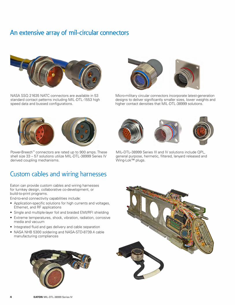
An extensive array of mil-circular connectorsAn extensive array of mil-circular connectors
Custom cables and wiring harnessesEaton can provide custom cables and wiring harnesses for turnkey design, collaborative co-development, or build-to-print programs. End-to-end connectivity capabilities include: • Application-specific solutions for high currents and voltages,
Ethernet, and RF applications • Single and multiple-layer foil and braided EMI/RFI shielding • Extreme temperatures, shock, vibration, radiation, corrosive media and vacuum
• Integrated fluid and gas delivery and cable separation • NASA NHB 5300 soldering and NASA-STD-8739.4 cable manufacturing compliances
NASA SSQ 21635 NATC connectors are available in 53 standard contact patterns including MIL--DTL--1553 high speed data and bussed configurations.
Power-Breech™ connectors are rated up to 900 amps. These shell size 33 – 57 solutions utilize MIL--DTL--38999 Series IV derived coupling mechanisms.
Micro-military circular connectors incorporate latest-generation designs to deliver significantly smaller sizes, lower weights and higher contact densities that MIL--DTL--38999 solutions.
MIL--DTL--38999 Series III and IV solutions include QPL, general purpose, hermetic, filtered, lanyard released and Wing-Lok™ plugs.
4 EATON MIL-DTL-38999 Series IV

Custom Breech-Lok™ connector capabilities
• Straight pull releases with as low as 90 pounds of force. • 15° off-angle separations with as low as 100 pounds of force.
• Designed to withstand 500 harsh-environment mating cycles and 100 snatch releases.
• Additional lanyard-plug modifications include redundant releases and custom and adjustable lanyard lengths.
• Breech-Lok™ lanyard release, flight heritage includes the Bell Helicopter V22 Osprey and the Eurocopter Tiger.
Breech-Lok™ custom lanyard solutions require significantly lower separation forces than D38999/31-compliant connectors
• High-speed data including: fiber optic, MIL-DTL-1553, USB, and 10/100/1000/10GBASE-T Ethernet.
• Contact configurations include split-pair quadrax, standard quadrax, differential twinax, and controlled impedance.
• A readily-available library of custom inserts such as four #8 power and eight #16 contacts in a size 23 shell.
• Power-Breech™ custom solutions providing up to 900 amps. • Additional customer-defined features: custom shell materials, platings, mounting flanges, backshells, strain reliefs, and extended coupling rings.
Custom inserts, shells, and accessories deliver high contact densities and application-optimized performance
• Custom solutions available with Class G finish, space-rated materials.
• Space-rated materials provide a total-mass loss of < 1% and contain < 0.1% volatile materials.
• Breech-Lok™ products have been space-flight approved by the NASA Goddard Space Flight Center.
• Flight heritage includes multiple space shuttle and satellite programs.
• Custom configurations available with the ergonomic Wing-Lok™ design are ideal for EVA and IVA applications.
Space rated, Breech-Lok™ technologies accelerate EVA and IVA custom-solution development
5EATON MIL-DTL-38999 Series IV

Modified MIL-DTL-38999 and full-custom solutions
• High-speed data including MIL-DTL-1553, USB, Ethernet and fiber optic.
• Standard and split-pair quadrax, differential twinax and controlled impedance contacts.
• Power solutions include D38999 Series IV derived Power-Breech™ connectors rated up to 900 amps.
• Additional application-specific features include custom materials, platings, mounting flanges, backshells, strain reliefs and extended coupling rings.
• Custom solutions are available with Class G finishes and space-rated materials that contain <0.1% volatile materials with a total-mass loss of <1%.
• D38999 Series IV, Breech-Lok™ connectors have been approved for space flight by the NASA Goddard Space Flight Center.
• Ergonomic Wing-Lok™ coupling rings (depicted to the left) facilitate rapid mating and demating when wearing bulky gloves in EVA and IVA applications.
• NATC-derived custom solution capabilities include thermally and electrically deadfaced connectors.
Eaton’s heritage-proven array of technologies and design platforms can be quickly leveraged to provide a wide range of harsh-environment interconnects: • Cryogenic and high temperature • Electrically and/or mechanically released • EVA and IVA quick disconnecting • Integrated electrical, gas and fluid • Interstage raceway • Low-imparted shock and zero-separation force • Positive-mate monitoring • Thermally and electrically deadfaced • Vertical launch
D38999 Series III and Series IV custom shells, inserts, and accessories
Space rated technologies accelerate EVA and IVA custom-solution development
Heritage-proven design platforms can be leveraged to quickly provide a wide range of custom solutions
6 EATON MIL-DTL-38999 Series IV

Innovative engineering facilitates cost effective, reusable solutions
Heritage-proven technologies and design platforms can be leveraged to quickly provide a wide range of custom, harsh-environment solutions for interconnect applications ranging from shoulder-fired missile launchers to deep space probes.
One example of Eaton’s track record of innovation is the umbilical connector described below. • MIL -DTL -38999 Series III derived shells and inserts reduce costs and leverage proven reliability and availability. Inserts can be upgraded to support changing mission requirements.
• A resettable release mechanism was developed based on a separation-nut design with over 40 years of flight heritage.
Umbilical cable plate
Umbilical-separation sequence
Host system mounted plate
Connector sockets mate with the host system wiring harness. The
opposing ends of these feedthroughs connect to the umbilical-cable plate.
1 Lanyard-actuated separation nut with double-shear dowel pin redundancy initiates umbilical separation.
2 Force-balanced spring towers work in conjunction with an ejector plate located in between the two connector plates to power separation.
3 The six sets of connectors simultaneously demate facilitating damage-free decoupling and reusability.
This lanyard connector integrates redundant-release mechanisms with standard MIL-DTL-38999 Series III coupling threads to support low-pull force, off-angle releases.
Connector pins mate with the umbilical cable. The opposing
ends of these feedthroughs mate to connectors mounted
on the stationary plate.
7EATON MIL-DTL-38999 Series IV

Power-Breech™ custom solutions up to 900 amps
Meets MIL-DTL-38999 Series IV performance requirements
Custom Power-Breech™ solutions provide MIL-DTL-38999 Series IV performance in configurations with large contacts and shell sizes that are not available in QPL solutions. A Series IV derived, breech-lock-coupling mechanism provides quick, positive engagements.
These heritage-proven design platforms can be customized to meet a wide range of mission-specific requirements: • Current ratings up to 900 amps. • Extreme shock, vibration, temperature, humidity, and EMI/RFI environments.
• Harsh-environment cable assemblies.
• ICBM program heritage; meets Boeing specifications 280-36501, 280-36503, 280-36505, and 280-36507.
• High-current capabilities include solutions configured with four, #4/0 contacts.
• Available with 2024 Al-alloy shells and CAD/OD (per QQ-P-416) finishes that withstand 500 hours salt spray.
• MIL-DTL-38999 Series IV derived, breech-mating designs survive 500 engagement cycles.
• Vibration and shock capabilities include MIL-STD-202, Method 204, Condition D and MIL-STD-38999H, Series IV.
• Positive-detent mechanism utilizes 270° of engagement rotation and provides visual, audible, and tactile mating indications.
• Shell designs are 100% scoop proof and are available in ten polarization configurations.
• Please contact Eaton at 800.840.0502 to discuss your high-current requirements.
These shell-size 41 connectors mate with 14 #8 contacts to provide a 640-amp current rating.
This Power-Breech™ solution utilizes four #4/0 contacts in a size 57 shell to provide 900 amps.
8 EATON MIL-DTL-38999 Series IV

Power-Breech™ technical specifications
Heritage-proven designs in shell sizes 33 - 57
Please contact Eaton to discuss how quickly custom Power-Breech™ solutions can be developed to meet your specific requirements.
The specifications listed below have been confirmed through customer qualifications of Power-Breech™ connectors designed for their harsh-environment applications. These heritage-proven specifications are presented as capabilities references.
Materials, Finish, and Mechanical
Shell and Coupling Ring Material 2024 Aluminum
Shell and Coupling Ring Plating CAD/OD per QQ-P-416
Contact Material & Plating Copper Alloy with Gold Plating, 50 Micro-Inches Minimum
Insulator Hard Dielectric Wafer
Grommet and Seal Fluorosilicone
Grounding Springs Beryllium Copper
Mating Life 500 Cycles Minimum
Contact Retention Up to 25 Pounds
Polarization 270° Engagement Rotation Available with Ten Different Polarizations
Electrical and Environmental
Current Ratings Up to 900 amps
Service Ratings Up to 2800 VRMS at Sea Level
Emi Leakage Attenuation > 85dB from 0.1 to 1,000MHz, 10dB Per Octave from 1,000 to 10,000MHz
Shell-to-Shell Conductivity 2.5 Millivolt Maximum Drop
Operating Temperature -65°C to 200°C (-85°F to 392°F)
Sealing Sand and Dust as per MIL-STD-202 and Ice Resistance
Corrosion Resistance Withstands 500 Hours Salt Spray
Fluid Immersion Various Fuels, Solvents, Coolants, and Oils as per EIA-364-10
Vibration Per MIL-STD-202, Method 204, Condition B
Shock EIA-364-27, Vibration: EIA-364-28
9EATON MIL-DTL-38999 Series IV

General purpose QPL and modified connectors
• Comprehensive range of QPL and modified solutions include Class G, space-rated connectors.
• High-speed-data configurations include MIL-STD-1553. • Grounding occurs 0.050 inch (1.27mm) before electrical-contact engagement.
• 360° grounding fingers provide up to 65dB protection at 1GHz.
• -65°C to 200°C operating temperatures. • Finish options include 500 hour salt-spray-rated platings. • Please contact customer service at 805.484.0543 to order products or receive additional information.
Breech-Lok™ solutions comprise one of the industry’s largest installed bases of MIL-DTL-38999 Series IV connectors. This track record of uncompromised reliability has been proven in harsh-environment applications ranging from weapons systems to spacecraft.
Breech-Lok™ products can be quickly customized to meet a broad array of mission-specific requirements: • Special insert patterns and shell configurations. • Customer-defined EMI/RFI compliances. • Custom connector/cable assemblies.
Field-proven performance in mission-critical applications
EMI ring
Metal contact retainer clips
High-strength coupling ring
Harsh-environment design features
Straight plugs
Feed-thru receptacles
Box-mount receptacles
In-line receptacles
Wall-mount receptaclesJam-nut receptacles
10 EATON MIL-DTL-38999 Series IV
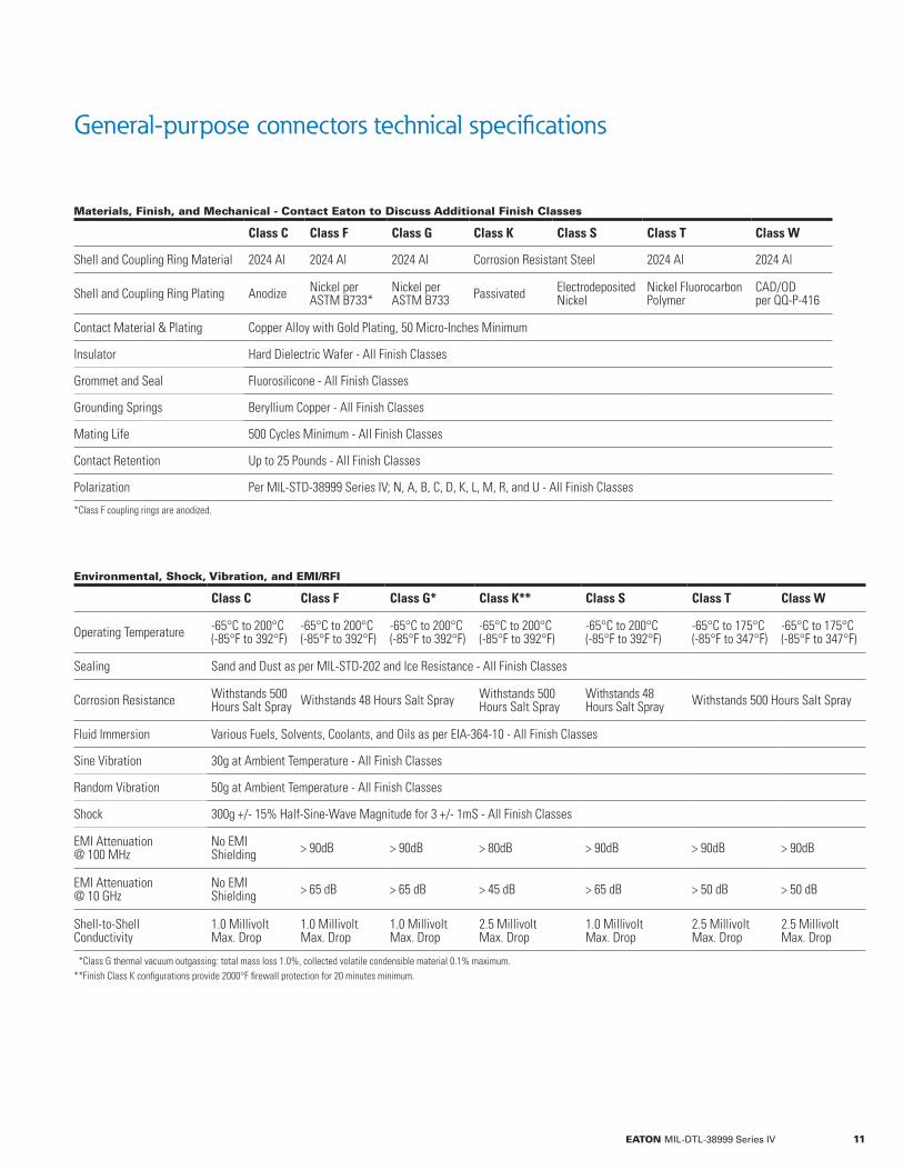
General-purpose connectors technical specifications
Materials, Finish, and Mechanical - Contact Eaton to Discuss Additional Finish Classes
Class C Class F Class G Class K Class S Class T Class W
Shell and Coupling Ring Material 2024 Al 2024 Al 2024 Al Corrosion Resistant Steel 2024 Al 2024 Al
Shell and Coupling Ring Plating Anodize Nickel per ASTM B733*
Nickel per ASTM B733 Passivated Electrodeposited
NickelNickel Fluorocarbon Polymer
CAD/OD per QQ-P-416
Contact Material & Plating Copper Alloy with Gold Plating, 50 Micro-Inches Minimum
Insulator Hard Dielectric Wafer - All Finish Classes
Grommet and Seal Fluorosilicone - All Finish Classes
Grounding Springs Beryllium Copper - All Finish Classes
Mating Life 500 Cycles Minimum - All Finish Classes
Contact Retention Up to 25 Pounds - All Finish Classes
Polarization Per MIL-STD-38999 Series IV; N, A, B, C, D, K, L, M, R, and U - All Finish Classes
*Class F coupling rings are anodized.
Environmental, Shock, Vibration, and EMI/RFI
Class C Class F Class G* Class K** Class S Class T Class W
Operating Temperature -65°C to 200°C (-85°F to 392°F)
-65°C to 200°C (-85°F to 392°F)
-65°C to 200°C (-85°F to 392°F)
-65°C to 200°C (-85°F to 392°F)
-65°C to 200°C (-85°F to 392°F)
-65°C to 175°C (-85°F to 347°F)
-65°C to 175°C (-85°F to 347°F)
Sealing Sand and Dust as per MIL-STD-202 and Ice Resistance - All Finish Classes
Corrosion Resistance Withstands 500Hours Salt Spray Withstands 48 Hours Salt Spray Withstands 500
Hours Salt SprayWithstands 48Hours Salt Spray Withstands 500 Hours Salt Spray
Fluid Immersion Various Fuels, Solvents, Coolants, and Oils as per EIA-364-10 - All Finish Classes
Sine Vibration 30g at Ambient Temperature - All Finish Classes
Random Vibration 50g at Ambient Temperature - All Finish Classes
Shock 300g +/- 15% Half-Sine-Wave Magnitude for 3 +/- 1mS - All Finish Classes
EMI Attenuation@ 100 MHz
No EMI Shielding > 90dB > 90dB > 80dB > 90dB > 90dB > 90dB
EMI Attenuation@ 10 GHz
No EMI Shielding > 65 dB > 65 dB > 45 dB > 65 dB > 50 dB > 50 dB
Shell-to-Shell Conductivity
1.0 Millivolt Max. Drop
1.0 Millivolt Max. Drop
1.0 Millivolt Max. Drop
2.5 MillivoltMax. Drop
1.0 MillivoltMax. Drop
2.5 Millivolt Max. Drop
2.5 Millivolt Max. Drop
**Class G thermal vacuum outgassing: total mass loss 1.0%, collected volatile condensible material 0.1% maximum.**Finish Class K configurations provide 2000°F firewall protection for 20 minutes minimum.
11EATON MIL-DTL-38999 Series IV

General-purpose connectors ordering information
Eaton part number
BL G6 W 11 - 35 P N
Breech-Lok™ Connector
Insert Arrangement (Page 13)
Contact Style(Table Below)
Polarization (Page 18)
Shell Type (Table Below)
Finish Class (Table Below)
Shell Size (Page 13)
MIL-DTL part number
D38999/ 46 W B 35 P N
MIL-DTL-38999Series IV Specification
Insert Arrangement (Page 13)
Contact Style(Table Below)
Polarization (Page 18)
Shell Type (Table Below)
Finish Class (Table Below)
Shell Size (Page 13)
*Class F coupling rings are anodized**PCB terminated contact part numbers are listed in the PC Tail Terminations section.
Designator Descriptions
Designator Type Military Eaton Description
Shell Type
MIL-DTL-38999/40 00 Wall-Mount Receptacle (Finish Class C, F, W, & K Configurations are QPL Certified)
MIL-DTL-38999/42 02 Box-Mount Receptacle (Finish class C, F, & W Configurations are QPL Certified)
MIL-DTL-38999/44 07 Jam-Nut Receptacle (Finish Class C, F, W, & K Configurations are QPL Certified)
MIL-DTL-38999/46 G6 EMI Straight Plug (Finish Class F, W, & K Configurations are QPL Certified)
MIL-DTL-38999/47 06 Non-EMI Straight Plug (Finish Class C, & W Configurations are QPL Ccertified)
MIL-DTL-38999/49 03 In-Line Receptacle (Finish Class C, F, & W Configurations are QPL Certified)
N/A 05 Bulkhead-Feed-Through Receptacle
Finish Class
C C Anodize, -65°C to 200°C (-85°F to 392°F)
F F Nickel per ASTM B733*, -65°C to 200°C (-85°F to 392°F)
G G Nickel per ASTM B733, -65°C to 200°C (-85°F to 392°F)
K K CRES (Passivated), -65°C to 200°C (-85°F to 392°F)
S S Electrodeposited Nickel, -65°C to 200°C (-85°F to 392°F)
T T Nickel Fluorocarbon Polymer, -65°C to 175°C (-85°F to 347°F)
W W CAD/OD per QQ-P-416, -65°C to 175°C (-85°F to 347°F)
Contact Style**
P P Pin
S S Socket
H H Pin, 1500 cycle
J J Socket, 1500 cycle
A A Pin, Connector Shipped Without Contacts
B B Socket, Connector Shipped Without Connectors
FeedthroughReceptacleContact Styles
P P Pin/Pin
S S Socket/Socket
A A Socket/Pin
B B Pin/Socket
12 EATON MIL-DTL-38999 Series IV

General-purpose connectors standard shell & insert configurations
Shell-Size Conversions
Military Designation A B C D E F G H J –
Shell Size & Eaton Designation 9 11 13 15 17 19 21 23 25 33
Please contact Eaton to discuss custom shells and inserts
ShellSize
Insert# SR Total #
Contacts# 22D
#20
#16
#12
#8
9 35 M 6 6
9 98 I 3 3
11 2 I 2 2
11 3* II 3 3
11 5 I 5 5
11 35 M 13 13
11 98 I 6 6
11 99 I 7 7
13 4 I 4 4
13 35 M 22 22
13 98 I 10 10
15 5 II 5 5
15 15 I 15 14 1
15 18 I 18 18
15 19 I 19 19
15 35 M 37 37
15 97 I 12 8 4
17 2* M,T 2 2T
17 6 I 6 6
17 8 II 8 8
17 26 I 26 26
17 35 M 55 55
17 98* M,T 26 24 2T
17 99 I 23 21 2
19 3* M,T 3 3T
19 4* M,T 4 4T
19 11 II 11 11
SR = Service Rating, T=Twinax, C=Coax, P=Power* Not a MIL-STD-1560 defined insert arrangement.
ShellSize
Insert# SR Total #
Contacts# 22D
#20
#16
#12
#10
#8
19 18 M,T 18 14 4T
19 32 I 32 32
19 35 M 66 66
21 5* M,T 5 5T
21 11 I 11 11
21 16 II 16 16
21 26* M,T 25 23 2T
21 35 M 79 79
21 39 I 39 37 2
21 41 I 41 41
23 21 II 21 21
23 35 M 100 100
23 53 I 53 53
23 55 I 55 55
23 97 I 16 16
23 99 II 11 11
25 4 I 56 48 8
25 8 M,T 8 8T
25 11 N 11 2 9
25 19 I 19 19
25 20 N,T,C 30 10 13 4C 3T
25 24 I 24 12 12
25 29 I 29 29
25 35 M 128 128
25 43 I 43 23 20
25 46 I,C 46 40 4 2C
25 61 I 61 61
33 54 I 54 30 14 6 4P
33 58 58 34 14 10
13EATON MIL-DTL-38999 Series IV

Insert and contact ratings
Insert Service Ratings
Suggested Operating Voltage (Sea Level)
Test Voltage(Sea level)
Test Voltage50,000 Ft.
Test Voltage70,000 Ft.
Test Voltage100,000 Ft.
Service Rating AC (RMS) DC
I 600 850 1800 VRMS 600 VRMS 400 VRMS 200 VRMS
II 900 1250 2300 VRMS 800 VRMS 500 VRMS 200 VRMS
M 400 550 1300 VRMS 550 VRMS 350 VRMS 200 VRMS
N 230 270 1000 VRMS 400 VRMS 260 VRMS 200 VRMS
Crimp Well Data Recommended Contact Rating (Amps)
Contact Size
Well Diameter
Minimum Well Depth
Wire Size (Awg)
28 26 24 22 20 18 16 14 12 10
22D .0345 ± .001 .141 1.5 2.0 3.0 5.0
20 .047 ± .001 .209 3.0 5.0 7.5
16 .067 ± .001 .209 7.5 10.0 13.0
12 .100 ± .002 .209 20.0 23.0
10 .137 ± .003 .355 23.0 33.0
Contact Part Number Cross Reference - PC tail contact information is listed on pages 53 and 54
Contact Size Eaton Part Number Military Part Number
Pin
22D 5034-2400-0220 M39029/58-360
20 5034-2400-0200 M39029/58-363
16 5034-2400-0160 M39029/58-364
12 5034-2400-0120 M39029/58-365
10 Contact Eaton M39029/58-528
12 COAX 5034-2428-12P00 M39029/28-211
12 COAX Contact Eaton M39029/102-558
8 TWINAX 5034-2507-08P00 M39029/90-529
8 POWER 5034-2488-0080 N / A
Socket
22D 5034-2600-0220 M39029/56-348
20 5034-2600-0200 M39029/56-351
16 5034-2600-0160 M39029/56-352
12 5034-2600-0120 M39029/56-353
10 5034-2600-0100 M39029/56-527
12 COAX 5034-2711-12S00 M39029/75-416
12 COAX Contact Eaton M39029/103-559
8 TWINAX 5034-2703-08S00 M39029/91-530
8 POWER 5034-2651-0080 N / A
14 EATON MIL-DTL-38999 Series IV
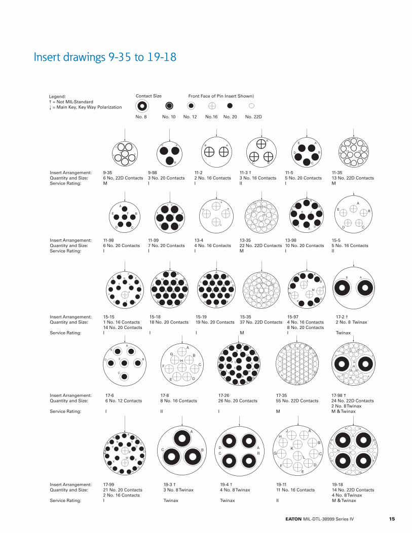
Insert drawings 9-35 to 19-18
Insert Arrangement:Quantity and Size:Service Rating:
9-356 No, 22D ContactsM
9-983 No. 20 ContactsI
11-22 No. 16 ContactsI
11-3 †3 No. 16 ContactsII
11-55 No. 20 ContactsI
11-3513 No. 22D ContactsM
Insert Arrangement:Quantity and Size:Service Rating:
11-986 No. 20 ContactsI
11-997 No. 20 ContactsI
13-44 No. 16 ContactsI
13-3522 No. 22D ContactsM
13-9810 No. 20 ContactsI
15-55 No. 16 ContactsII
Insert Arrangement:Quantity and Size:
Service Rating:
15-151 No. 16 Contacts14 No. 20 ContactsI
15-1818 No. 20 Contacts
I
15-1919 No. 20 Contacts
I
15-3537 No. 22D Contacts
M
15-974 No. 16 Contacts8 No. 20 ContactsI
17-2 †2 No. 8 Twinax
Twinax
Insert Arrangement:Quantity and Size:
Service Rating:
17-66 No. 12 Contacts
I
17-88 No. 16 Contacts
II
17-2626 No. 20 Contacts
I
17-3555 No. 22D Contacts
M
17-98 †24 No. 22D Contacts2 No. 8 TwinaxM & Twinax
Insert Arrangement:Quantity and Size:
Service Rating:
17-9921 No. 20 Contacts2 No. 16 ContactsI
19-3 †3 No. 8 Twinax
Twinax
19-4 †4 No. 8 Twinax
Twinax
19-1111 No. 16 Contacts
II
19-1814 No. 22D Contacts4 No. 8 TwinaxM & Twinax
Front Face of Pin Insert Shown)Legend:† = Not MIL-Standard = Main Key, Key Way Polarization
Contact Size
No. 10 No. 12 No.16 No. 20 No. 22DNo. 8
15EATON MIL-DTL-38999 Series IV

Insert drawings 19-32 to 25-4
Insert Arrangement: Quantity and Size:Service Rating:
19-3232 No. 20 ContactsI
19-3566 No. 22D ContactsM
21-5 † 5 No. 8 ContactsM
21-1111 No. 12 ContactsI
Insert Arrangement:Quantity and Size:
Service Rating::
21-1616 No. 16 Contacts
II
21-26 † 23 No. 20 Contacts2 No. 8 ContactsM
21-3579 No. 22D Contacts2 No. 16 ContactsM
21-3937 No. 20 Contacts2 No. 16 ContactsI
Insert Arrangement: Quantity and Size:Service Rating:
21-4141 No. 20 ContactsI
23-2121 No. 16 ContactsII
23-35100 No. 22D ContactsM
23-5353 No. 20 ContactsI
Insert Arrangement: Quantity and Size:Service Rating:
23-5555 No. 20 ContactsI
23-9716 No. 16 ContactsI
23-9911 No. 16 ContactsII
Front Face of Pin Insert Shown)
25-448 No. 20 Contacts8 No. 16 ContactsI
Contact SizeLegend:† = Not MIL-Standard = Main Key, Key Way Polarization
No. 10 No. 12 No.16 No. 20 No. 22DNo. 8 (TWINAX)
No. 8 Power Contacts
16 EATON MIL-DTL-38999 Series IV

Insert drawings 25-8 to 33-58
A BC
D
E
F
G
H
J
K
L
MN
PRS
T
U
V
W
X
Y
Z
a
b c
d e f
g h
j
k
l
m
n
P
q
r
s
t
u
y w
x
CC y
DD EEGG
FF
BB Z
AA
56 4853 58
47
1 23
4
5
6
7
25
26
27
28
29
24
4645
2322
2144
20 43
42
41
19
18
4017
3916
15
14 3513
35
5033
1234 11
10
32 9
31
30
38 3751
54 55
4952 57
25-88 No. 8 Contacts
Twinax
25-112 No. 20 Contacts9 No. 10 Contacts
N
25-1919 No. 12 Contacts
I
Insert Arrangement: Quantity and Size:
Service Rating:
25-2010 No. 20 Contacts13 No. 16 Contacts4 No. 12 Contacts3 No. 8 ContactsN
25-2412 No. 16 Contacts12 No. 12 ContactsI
25-2929 No. 16 Contacts
I
25-35128 No. 22D Contacts
M
Insert Arrangement:Quantity and Size:
Service Rating:
25-4323 No. 20 Contacts20 No. 16 ContactsI
25-4640 No. 20 Contacts4 No. 16 Contacts2 No. 8 Contacts
I
25-6161 No. 20 Contacts
I
33-5430 No. 20 Contacts14 No. 16 Contacts6 No. 12 Contacts4 No. 8 Power ContactsI
33-5834 No. 20 Contacts14 No. 16 Contacts10 No. 12 Contacts
I
Insert Arrangement: Quantity and Size:
Service Rating:
Front Face of Pin Insert Shown)Legend:† = Not MIL-Standard = Main Key, Key Way Polarization
Contact Size
No. 10 No. 12 No.16 No. 20 No. 22DNo. 8 (TWINAX)
No. 8 Power Contacts
17EATON MIL-DTL-38999 Series IV

Polarization tables
YY°
XX°
YY°
XX°
Plugs Receptacles
Polarization XX° YY°
N 110° 250°
A 100° 260°
B 90° 270°
C 80° 280°
D 70° 290°
K 120° 255°
L 120° 265°
M 120° 275°
R 120° 285°
U 0° 0°
18 EATON MIL-DTL-38999 Series IV

D38999/46 & 47 straight plugs, Eaton types G6 & 06
ShellSize
U Reference ØBMax
ØCMax
ØMMax
VThreadSocket Pin
9 0.116(2.95)
0.076(1.93)
0.650(16.51)
0.935(23.75)
0.523(13.28) M12x1.0-6g-0.1R
11 0.116(2.95)
0.076(1.93)
0.775(19.69)
1.047(26.59)
0.644(16.36) M15x1.0-6g-0.1R
13 0.117(2.97)
0.077(1.96)
0.901(22.89)
1.220(30.99)
0.765(19.43) M18x1.0-6g-0.1R
15 0.137(3.48)
0.097(2.46)
1.039(26.39)
1.346(34.19)
0.889(22.58) M22x1.0-6g-0.1R
17 0.137(3.48)
0.097(2.46)
1.149(29.18)
1.472(37.39)
1.014(25.76) M25x1.0-6g-0.1R
19 0.157(3.99)
0.117(2.97)
1.275(32.39)
1.582(40.18)
1.094(27.79) M28x1.0-6g-0.1R
21 0.157(3.99)
0.117(2.97)
1.401(35.59)
1.704(43.28)
1.219(30.96) M31x1.0-6g-0.1R
23 0.177(4.50)
0.137(3.48)
1.527(38.79)
1.831(46.51)
1.348(34.24) M34x1.0-6g-0.1R
25 0.177(4.50)
0.137(3.48)
1.649(41.88)
1.957(49.71)
1.475(37.47) M37x1.0-6g-0.1R
33 0.229(5.82)
0.181(4.60)
2.200(55.88)
2.515(63.88)
1.908(48.46) M47x1.0-6g-0.1R
Dimensions are stated as inches (mm).
0.19” Min.(4.80 mm)
1.06” Max.(26.92 mm)
øC øB
(øM)Keyway Major
U Master Keyway
1.44”Max. Mated (36.58 mm)1.53” Max. Unmated(38.86 mm)
O-RingEMI Grounding Ring
Blue Color BandRed Unmated Indicator
V Thread
Wire SealingGrommet
0.09” Max.(2.29 mm)
19EATON MIL-DTL-38999 Series IV

D38999/40 wall-mount receptacles, Eaton type 00
ShellSize
ØCMax
ØDMax
ØJBoss Max
ØMRef
ØPMin
RBSC
SMax
U reference VThreadSocket Pin
9 0.102(2.59)
0.384(9.75)
0.668(16.97)
0.464(11.79)
0.122(3.10)
0.328(8.33)
0.948(24.08)
0.065(1.65)
0.105(2.67) M12x1.0-6g-0.1R
11 0.102(2.59)
0.509(12.93)
0.793(20.14)
0.589(14.96)
0.122(3.10)
0.406(10.31)
1.051(26.70)
0.065(1.65)
0.105(2.67) M15x1.0-6g-0.1R
13 0.102(2.59)
0.634(16.10)
0.919(23.34)
0.720(18.29)
0.122(3.10)
0.453(11.51)
1.146(29.11)
0.065(1.65)
0.105(2.67) M18x1.0-6g-0.1R
15 0.102(2.59)
0.759(19.28)
1.044(26.52)
0.844(21.44)
0.122(3.10)
0.484(12.31)
1.240(31.50)
0.085(2.16)
0.125(3.18) M22x1.0-6g-0.1R
17 0.102(2.59)
0.885(22.48)
1.170(29.72)
0.969(24.61)
0.122(3.10)
0.531(13.49)
1.335(33.91)
0.085(2.16)
0.125(3.18) M25x1.0-6g-0.1R
19 0.102(2.59)
1.009(25.63)
1.294(32.87)
1.088(27.64)
0.122(3.10)
0.578(14.68)
1.461(37.11)
0.105(2.67)
0.145(3.68) M28x1.0-6g-0.1R
21 0.133(3.38)
1.134(28.80)
1.419(36.04)
1.213(30.81)
0.122(3.10)
0.625(15.88)
1.583(40.21)
0.105(2.67)
0.145(3.68) M31x1.0-6g-0.1R
23 0.133(3.38)
1.259(31.98)
1.544(39.22)
1.342(34.09)
0.142(3.61)
0.687(17.46)
1.709(43.41)
0.125(3.18)
0.165(4.19) M34x1.0-6g-0.1R
25 0.133(3.38)
1.384(35.15)
1.669(42.39)
1.469(37.31)
0.142(3.61)
0.750(19.05)
1.835(46.61)
0.125(3.18)
0.165(4.19) M37x1.0-6g-0.1R
33 0.133(3.38)
1.811(46.00)
2.220(56.39)
1.902(48.31)
0.142(3.61)
1.000(25.40)
2.356(59.84)
0.165(4.19)
0.217(5.51) M47x1.0-6g-0.1R
Dimensions are stated as inches (mm).
ØP4 Holes
U
ØMKey Major
R Typ. R Typ.
91°
Blue Full Mate Indicator
0.81” Max.(20.57 mm)
1.26” Max.(32.00 mm)
0.04” Max.(1.02 mm)
0.09” Max.(2.29 mm)
Wire SealingGrommet
V Thread
Blue Color BandS Typ.
ØJBoss
ØD
C
20 EATON MIL-DTL-38999 Series IV

D38999/42 box-mount receptacles, Eaton type 02
ShellSize
CMax
ØDMax
ØJBoss Max
ØMRef
ØPMin
RBSC
SMax
U reference ØVMax
ØWMaxSocket Pin
9 0.102(2.59)
0.384(9.75)
0.668(16.97)
0.464(11.79)
0.122(3.10)
0.328(8.33)
0.948(24.08)
0.065(1.65)
0.105(2.67)
0.412(10.46)
0.453(11.51)
11 0.102(2.59)
0.509(12.93)
0.793(20.14)
0.589(14.96)
0.122(3.10)
0.406(10.31)
1.051(26.7)
0.065(1.65)
0.105(2.67)
0.535(13.59)
0.578(14.68)
13 0.102(2.59)
0.634(16.10)
0.919(23.34)
0.720(18.29)
0.122(3.10)
0.453(11.51)
1.146(29.11)
0.065(1.65)
0.105(2.67)
0.649(16.48)
0.692(17.58)
15 0.102(2.59)
0.759(19.28)
1.044(26.52)
0.844(21.44)
0.122(3.10)
0.484(12.31)
1.240(31.50)
0.085(2.16)
0.125(3.18)
0.771(19.58)
0.818(20.78)
17 0.102(2.59)
0.885(22.48)
1.170(29.72)
0.969(24.61)
0.122(3.10)
0.531(13.49)
1.335(33.91)
0.085(2.16)
0.125(3.18)
0.897(22.78)
0.944(23.98)
19 0.102(2.59)
1.009(25.63)
1.294(32.87)
1.088(27.64)
0.122(3.10)
0.578(14.68)
1.461(37.11)
0.105(2.67)
0.145(3.68)
1.003(25.48)
1.051(26.70)
21 0.133(3.38)
1.134(28.80)
1.419(36.04)
1.213(30.81)
0.122(3.10)
0.625(15.88)
1.583(40.21)
0.105(2.67)
0.145(3.68)
1.129(28.68)
1.173(29.79)
23 0.133(3.38)
1.259(31.98)
1.544(39.22)
1.342(34.09)
0.142(3.61)
0.687(17.46)
1.709(43.41)
0.125(3.18)
0.165(4.19)
1.255(31.88)
1.299(32.99)
25 0.133(3.38)
1.384(35.15)
1.669(42.39)
1.469(37.31)
0.142(3.61)
0.750(19.05)
1.835(46.61)
0.125(3.18)
0.165(4.19)
1.377(34.98)
1.425(36.20)
33 0.133(3.38)
1.811(46.00)
2.220(56.39)
1.902(48.31)
0.142(3.61)
1.000(25.40)
2.356(59.84)
0.165(4.19)
0.217(5.51)
1.839(46.71)
1.925(48.90)
Dimensions are stated as inches (mm).
ØP4 Holes
U
ØMKey Major
R Typ.
S Typ.
R Typ.
91°
Blue Full MateIndicator
0.81” Max.(20.57 mm)
0.14” Max.(3.56 mm)
0.14” Max.(3.56 mm)
1.26” Max.(32.00 mm)
0.04” Max.(1.02 mm)
0.09” Max.(2.29 mm)
Wire SealingGrommet
Blue Color Band
ØJBoss
ØD ØV ØW
C
21EATON MIL-DTL-38999 Series IV
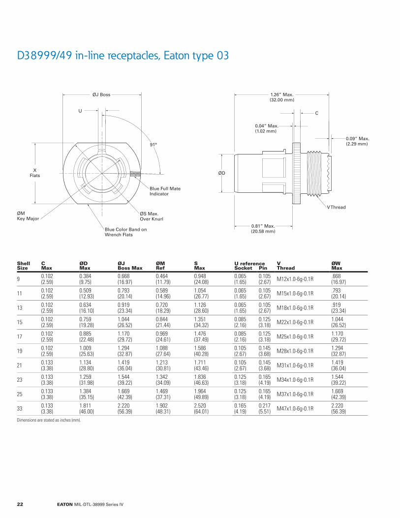
D38999/49 in-line receptacles, Eaton type 03
ShellSize
CMax
ØDMax
ØJBoss Max
ØMRef
SMax
U reference VThread
ØWMaxSocket Pin
9 0.102(2.59)
0.384(9.75)
0.668(16.97)
0.464(11.79)
0.948(24.08)
0.065(1.65)
0.105(2.67) M12x1.0-6g-0.1R .668
(16.97)
11 0.102(2.59)
0.509(12.93)
0.793(20.14)
0.589(14.96)
1.054(26.77)
0.065(1.65)
0.105(2.67) M15x1.0-6g-0.1R .793
(20.14)
13 0.102(2.59)
0.634(16.10)
0.919(23.34)
0.720(18.29)
1.126(28.60)
0.065(1.65)
0.105(2.67) M18x1.0-6g-0.1R .919
(23.34)
15 0.102(2.59)
0.759(19.28)
1.044(26.52)
0.844(21.44)
1.351(34.32)
0.085(2.16)
0.125(3.18) M22x1.0-6g-0.1R 1.044
(26.52)
17 0.102(2.59)
0.885(22.48)
1.170(29.72)
0.969(24.61)
1.476(37.49)
0.085(2.16)
0.125(3.18) M25x1.0-6g-0.1R 1.170
(29.72)
19 0.102(2.59)
1.009(25.63)
1.294(32.87)
1.088(27.64)
1.586(40.28)
0.105(2.67)
0.145(3.68) M28x1.0-6g-0.1R 1.294
(32.87)
21 0.133(3.38)
1.134(28.80)
1.419(36.04)
1.213(30.81)
1.711(43.46)
0.105(2.67)
0.145(3.68) M31x1.0-6g-0.1R 1.419
(36.04)
23 0.133(3.38)
1.259(31.98)
1.544(39.22)
1.342(34.09)
1.836(46.63)
0.125(3.18)
0.165(4.19) M34x1.0-6g-0.1R 1.544
(39.22)
25 0.133(3.38)
1.384(35.15)
1.669(42.39)
1.469(37.31)
1.964(49.89)
0.125(3.18)
0.165(4.19) M37x1.0-6g-0.1R 1.669
(42.39)
33 0.133(3.38)
1.811(46.00)
2.220(56.39)
1.902(48.31)
2.520(64.01)
0.165(4.19)
0.217(5.51) M47x1.0-6g-0.1R 2.220
(56.39)Dimensions are stated as inches (mm).
U
ØMKey Major
ØS Max.Over Knurl
V Thread
Blue Color Band onWrench Flats
Blue Full MateIndicator
XFlats
91°
1.26” Max.(32.00 mm)
ØJ Boss
ØD
C
0.81” Max.(20.58 mm)
0.04” Max.(1.02 mm)
0.09” Max.(2.29 mm)
22 EATON MIL-DTL-38999 Series IV

D38999/44 jam-nut receptacles, Eaton type 07
Shell Size
ØBMax
CMax
ØDMax
ØEMax
GThread
H FlatMax
VThread
Jam nutD389999/28Dash no.
O-ringMS9068Dash no.
9 1.195(30.35)
0.651(16.54)
0.680(17.27)
0.384(9.75) M17x1.0-6g-0.1R 1.073
(27.25) M12x1.0-6g-0.1R -2 -018
11 1.520(38.61)
0.942(23.93)
1.000(25.40)
0.509(12.93) M25x1.0-6g-0.1R 1.394
(35.41) M15x1.0-6g-0.1R -3 -024
13 1.642(41.71)
1.066(27.08)
1.125(28.58)
0.634(16.10) M28x1.0-6g-0.1R 1.520
(38.61) M18x1.0-6g-0.1R -4 -026
15 1.768(44.91)
1.191(30.25)
1.250(31.75)
0.759(19.28) M31x1.0-6g-0.1R 1.642
(41.71) M22x1.0-6g-0.1R -5 -028
17 1.957(49.71)
1.321(33.55)
1.375(34.93)
0.885(22.48) M34x1.0-6g-0.1R 1.799
(45.69) M25x1.0-6g-0.1R -7 -029
19 2.035(51.69)
1.441(36.60)
1.500(38.10)
1.009(25.63) M38x1.0-6g-0.1R 1.909
(48.49) M28x1.0-6g-0.1R -9 -030
21 2.157(54.79)
1.566(39.78)
1.625(41.28)
1.134(28.80) M41x1.0-6g-0.1R 2.035
(51.69) M31x1.0-6g-0.1R -10 -031
23 2.283(57.99)
1.691(42.95)
1.750(44.45)
1.259(31.98) M44x1.0-6g-0.1R 2.157
(54.79) M34x1.0-6g-0.1R -11 -032
25 2.409(61.19)
1.816(46.13)
1.875(47.63)
1.384(35.15) M47x1.0-6g-0.1R 2.283
(57.99) M37x1.0-6g-0.1R -12 -033
33 3.015(76.58)
2.208(56.08)
2.264(57.51)
1.811(46.00) 2.250-16 UN-2A 2.737
(69.52) M47x1.0-6g-0.1R N/A -037
Dimensions are stated as inches (mm).
91°ØB
ØDBoss
G Thread
V Thread
Blue Band
O-Ring(See Table)
1.12” Max.( 28.45 mm)
ØE
BlueFull MateIndicator
2X H
CFlat
23EATON MIL-DTL-38999 Series IV
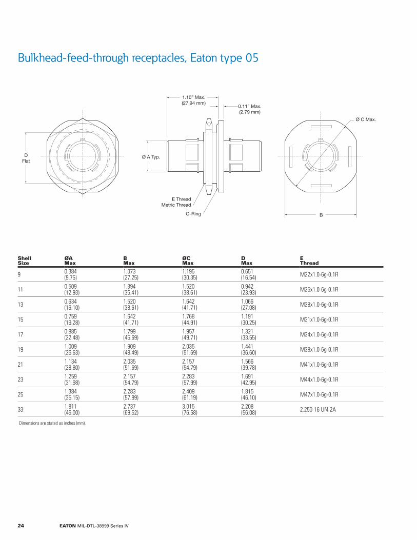
Bulkhead-feed-through receptacles, Eaton type 05
Shell Size
ØAMax
BMax
ØCMax
DMax
EThread
9 0.384(9.75)
1.073(27.25)
1.195(30.35)
0.651(16.54) M22x1.0-6g-0.1R
11 0.509(12.93)
1.394(35.41)
1.520(38.61)
0.942(23.93) M25x1.0-6g-0.1R
13 0.634(16.10)
1.520(38.61)
1.642(41.71)
1.066(27.08) M28x1.0-6g-0.1R
15 0.759(19.28)
1.642(41.71)
1.768(44.91)
1.191(30.25) M31x1.0-6g-0.1R
17 0.885(22.48)
1.799(45.69)
1.957(49.71)
1.321(33.55) M34x1.0-6g-0.1R
19 1.009(25.63)
1.909(48.49)
2.035(51.69)
1.441(36.60) M38x1.0-6g-0.1R
21 1.134(28.80)
2.035(51.69)
2.157(54.79)
1.566(39.78) M41x1.0-6g-0.1R
23 1.259(31.98)
2.157(54.79)
2.283(57.99)
1.691(42.95) M44x1.0-6g-0.1R
25 1.384(35.15)
2.283(57.99)
2.409(61.19)
1.815(46.10) M47x1.0-6g-0.1R
33 1.811(46.00)
2.737(69.52)
3.015(76.58)
2.208(56.08) 2.250-16 UN-2A
Dimensions are stated as inches (mm).
Ø A Typ.
Ø C Max.
DFlat
O-Ring
E ThreadMetric Thread
B
0.11” Max.(2.79 mm)
1.10” Max.(27.94 mm)
24 EATON MIL-DTL-38999 Series IV
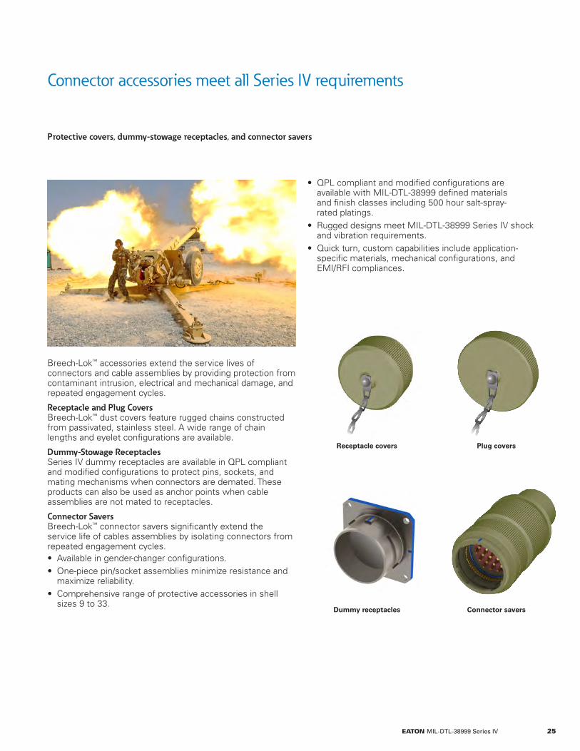
Connector accessories meet all Series IV requirements
Protective covers, dummy-stowage receptacles, and connector savers
Breech-Lok™ accessories extend the service lives of connectors and cable assemblies by providing protection from contaminant intrusion, electrical and mechanical damage, and repeated engagement cycles.
Receptacle and Plug Covers Breech-Lok™ dust covers feature rugged chains constructed from passivated, stainless steel. A wide range of chain lengths and eyelet configurations are available.
Dummy-Stowage Receptacles Series IV dummy receptacles are available in QPL compliant and modified configurations to protect pins, sockets, and mating mechanisms when connectors are demated. These products can also be used as anchor points when cable assemblies are not mated to receptacles.
Connector Savers Breech-Lok™ connector savers significantly extend the service life of cables assemblies by isolating connectors from repeated engagement cycles. • Available in gender-changer configurations. • One-piece pin/socket assemblies minimize resistance and maximize reliability.
• Comprehensive range of protective accessories in shell sizes 9 to 33.
• QPL compliant and modified configurations are available with MIL-DTL-38999 defined materials and finish classes including 500 hour salt-spray- rated platings.
• Rugged designs meet MIL-DTL-38999 Series IV shock and vibration requirements.
• Quick turn, custom capabilities include application-specific materials, mechanical configurations, and EMI/RFI compliances.
Receptacle covers
Dummy receptacles
Plug covers
Connector savers
25EATON MIL-DTL-38999 Series IV

Part number configuration
Receptacle and plug covers ordering information
Eyelet-Size Codes
Code Description Code Description
0 No Eyelet 5 0.219 Eyelet
1 0.125 dia. Eyelet 6 0.250 Eyelet
2 0.140 dia. Eyelet R Ring
3 0.167 dia. Eyelet S Split Ring
4 0.188 dia. Eyelet
Designator Descriptions
Designator Type Eaton Description
Cover TypeRC Receptacle Cover
PC Plug Cover
Finish Class
C Anodize, -65°C to 200°C (-85°F to 392°F)
F Nickel per ASTM B733, -65°C to 200°C (-85°F to 392°F)
G Nickel per ASTM B733, -65°C to 200°C (-85°F to 392°F)
K CRES (Passivated), -65°C to 200°C (-85°F to 392°F)
N Nickel Plate per ASTM B733, -65°C to 200°C (-85°F to 392°F)
S Electrodeposited Nickel, -65°C to 200°C (-85°F to 392°F)
T Nickel Fluorocarbon Polymer, -65°C to 175°C (-85°F to 347°F)
W CAD/OD per QQ-P-416, -65°C to 175°C (-85°F to 347°F)
Y Passivated per SAE-AMS-QQ-P-35, -65°C to 200°C (-85°F to 392°F)
EMI CodesG EMI grounding, Receptacle Covers Only
O No EMI Grounding
Chain-Type Codes
Code Description Code Description
0 No Chain P CRES Cable, PVC Jacket
L CRES Link Chain T CRES Cable, Teflon Jacket
B CRES Bead Chain U CRES Cable, Nylon Jacket
C CRES Cable, No Jacket V CRES Cable, Viton Jacket
BL RC F 11 - G L 5 3 - 000
Breech-Lok™ Connector
Chain Length (Whole-Number Inches)
Eyelet Size Code (Table Below)
Modification Code(Custom Solutions Only)
Cover Type (Table Below)
Finish Class (Table Below)
Shell Size (Pages 27 & 28) Chain Type (Table Below)EMI Code (Table Below)
26 EATON MIL-DTL-38999 Series IV

Receptacle covers mechanical drawings
FinishClasses All All
All Except N & Y
All Except N & Y N & Y N & Y
ShellSize
ØAMax
ØBMax
ØDMin
ØEMin
ØDMin
ØEMin
9 0.880(22.35)
0.650(16.51)
0.685(17.40)
0.722(18.34)
0.685(17.40)
0.722(18.34)
11 0.922(23.42)
0.775(19.69)
1.006(25.55)
0.880(22.35)
0.809(20.55)
0.781(19.84)
13 1.047(26.59)
0.900(22.86)
1.124(28.55)
0.959(24.36)
1.006(25.55)
0.880(22.35)
15 1.219(30.96)
1.040(26.42)
1.248(31.70)
1.057(26.85)
1.124(28.55)
0.959(24.36)
17 1.344(34.14)
1.150(29.21)
1.367(34.72)
1.057(26.85)
1.288(32.72)
0.978(24.84)
19 1.469(37.31)
1.275(32.39)
1.524(38.71)
1.156(29.36)
1.406(35.71)
1.057(26.85)
21 1.579(40.11)
1.400(35.56)
1.642(41.71)
1.234(31.34)
1.524(38.71)
1.156(29.36)
23 1.704(43.28)
1.525(38.74)
1.760(44.70)
1.258(31.95)
1.642(41.71)
1.234(31.34)
25 1.829(46.46)
1.650(41.91)
1.878(47.70)
1.333(33.86)
1.760(44.70)
1.258(31.95)
33 2.329(59.16)
2.200(55.88)
2.282(57.96)
1.565(39.75) N/A N/A
Dimensions are stated as inches (mm).
1.38” Max.(35.05 mm)
0.19” Min.(4.83 mm)
ØAMax.
ØBMax.
ØD
ØD
E
E
Attachment with ring
Attachment with split ring
27EATON MIL-DTL-38999 Series IV
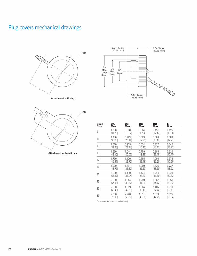
Plug covers mechanical drawings
Shell Size
ØAMax
ØBMax
ØCMax
ØDMax
EMin
9 1.250(31.75)
0.668(16.97)
0.384(9.75)
0.491(12.47)
0.425(10.80)
11 1.380(35.05)
0.793(20.14)
0.509(12.93)
0.609(15.47)
0.483(12.27)
13 1.570(39.88)
0.919(23.34)
0.634(16.10)
0.727(18.47)
0.542(13.77)
15 1.660(42.16)
1.044(26.52)
0.759(19.28)
0.885(22.48)
0.620(15.75)
17 1.790(45.47)
1.170(29.72)
0.885(22.48)
1.008(25.60)
0.679(17.25)
19 1.920(48.77)
1.294(32.87)
1.009(25.63)
1.126(28.60)
0.737(18.72)
21 2.060(52.32)
1.419(36.04)
1.134(28.80)
1.244(31.60)
0.820(20.83)
23 2.250(57.15)
1.544(39.22)
1.259(31.98)
1.367(34.72)
0.851(21.62)
25 2.380(60.45)
1.669(42.39)
1.384(35.15)
1.485(37.72)
0.910(23.11)
33 2.880(73.15)
2.220(56.39)
1.811(46.00)
1.879(47.73)
1.025(26.04)
Dimensions are stated as inches (mm).
0.81” Max.(20.57 mm)
0.64” Max.(16.26 mm)
1.44” Max.(36.58 mm)
ØBMax.Boss
ØAMax.OverKnurl
ØC Max.
ØD
ØD
E
E
Attachment with ring
Attachment with split ring
28 EATON MIL-DTL-38999 Series IV

Dummy-stowage receptacles mechanical drawings and ordering information
Shell Size
CRef
ØEMax
ØFRef
ØGRef
RBSC
SMax
URef
9 0.102(2.59)
0.384(9.75)
0.461(11.71)
0.137(3.48)
0.328(8.33)
0.950(24.13)
0.065(1.65)
11 0.102(2.59)
0.509(12.93)
0.589(14.96)
0.137(3.48)
0.406(10.31)
1.051(26.70)
0.065(1.65)
13 0.102(2.59)
0.634(16.10)
0.720(18.29)
0.137(3.48)
0.453(11.51)
1.145(29.08)
0.065(1.65)
15 0.102(2.59)
0.759(19.28)
0.844(21.44)
0.137(3.48)
0.485(12.32)
1.240(31.50)
0.085(2.16)
17 0.102(2.59)
0.885(22.48)
0.969(24.61)
0.137(3.48)
0.531(13.49)
1.334(33.88)
0.085(2.16)
19 0.133(3.38)
1.009(25.63)
1.088(27.64)
0.137(3.48)
0.578(14.68)
1.460(37.08)
0.105(2.67)
21 0.133(3.38)
1.134(28.80)
1.213(30.81)
0.137(3.48)
0.625(15.88)
1.582(40.18)
0.105(2.67)
23 0.133(3.38)
1.259(31.98)
1.342(34.09)
0.157(3.99)
0.688(17.48)
1.708(43.38)
0.125(3.18)
25 0.133(3.38)
1.384(35.15)
1.469(37.31)
0.157(3.99)
0.750(19.05)
1.834(46.58)
0.125(3.18)
33 0.133(3.38)
1.811(46.00)
1.905(48.39)
0.157(3.99)
1.00(25.40)
2.345(59.56)
0.165(4.19)
Dimensions are stated as inches (mm).
Part number Configuration
BL DR C 11 N
Breech-Lok™ Series IV Configuration Polarization (Page 18)
Shell Size (Table Below)Dummy Receptacle
Finish Class (Page 12)
R Typ.R Typ.
S Typ.
0.81” Max.(20.57 mm)
C
U
91°
Ø G4 X
Ø FKey Major
BlueFull MateIndicator
Ø E
29EATON MIL-DTL-38999 Series IV

Connector savers mechanical drawings and ordering information
Shell Size ØA Max ØB Max ØC Max
9 0.935 (23.75)
0.384 (9.75)
0.801 (20.35)
11 1.054 (26.77)
0.509 (12.93)
0.926 (23.52)
13 1.226 (31.14)
0.634 (16.10)
1.040 (26.42)
15 1.351 (34.32)
0.759 (19.28)
1.165 (29.59)
17 1.476 (37.49)
0.885 (22.48)
1.290 (32.77)
19 1.586 (40.28)
1.009 (25.63)
1.396(35.46)
21 1.711 (43.46)
1.134 (28.80)
1.521 (38.63)
23 1.536(39.01)
1.259 (31.98)
1.646 (41.81)
25 1.964 (49.89)
1.384 (35.15)
1.771 (44.98)
33 2.515 (63.88)
1.811 (46.00)
2.198 (55.83)
Dimensions are stated as inches (mm).
Part number configuration
BL CS F 15 - 35 P N - 170
Shell Polarization (Page 18)
Breech-Lok™ Series IV Configuration Modification Code-170 Connector Saver
Connector Saver
Finish Class (Page 12)
Shell Size (Table Below)
Contact StyleP = Pin Plug. Pin ReceptacleS = Socket Plug. Socket ReceptacleA = Socket Plug. Pin ReceptacleB = Pin Plug. Socket ReceptacleInsert Arrangement (Page 13)
A ØMax.
C ØMax.
Adaptor Ring Must Be RestrainedWhile Mating Cable Mounted Plug Assy.
2.94” Max.(74.68 mm)
B ØMax.
30 EATON MIL-DTL-38999 Series IV
Wing-Lok™ plugs meet all Series IV requirements
EMI ring
Metal contact retainer clips
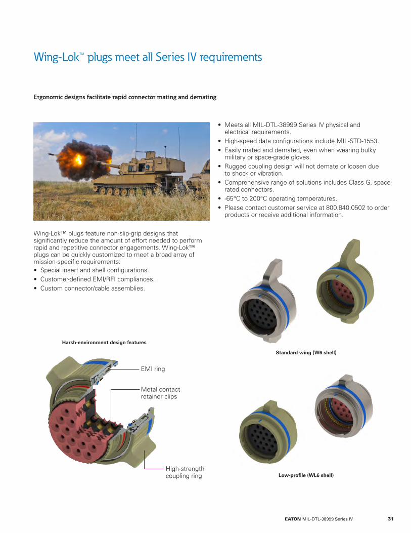
Ergonomic designs facilitate rapid connector mating and demating
Wing-Lok™ plugs feature non-slip-grip designs that significantly reduce the amount of effort needed to perform rapid and repetitive connector engagements. Wing-Lok™ plugs can be quickly customized to meet a broad array of mission-specific requirements: • Special insert and shell configurations. • Customer-defined EMI/RFI compliances. • Custom connector/cable assemblies.
• Meets all MIL-DTL-38999 Series IV physical and electrical requirements.
• High-speed data configurations include MIL-STD-1553. • Easily mated and demated, even when wearing bulky military or space-grade gloves.
• Rugged coupling design will not demate or loosen due to shock or vibration.
• Comprehensive range of solutions includes Class G, space-rated connectors.
• -65°C to 200°C operating temperatures. • Please contact customer service at 800.840.0502 to order products or receive additional information.
High-strength coupling ring
Standard wing (W6 shell)
Low-profile (WL6 shell)
Harsh-environment design features
31EATON MIL-DTL-38999 Series IV
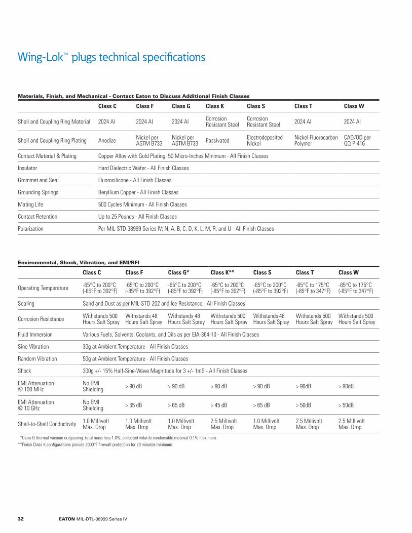
Wing-Lok™ plugs technical specifications
Materials, Finish, and Mechanical - Contact Eaton to Discuss Additional Finish Classes
Class C Class F Class G Class K Class S Class T Class W
Shell and Coupling Ring Material 2024 Al 2024 Al 2024 Al Corrosion Resistant Steel
Corrosion Resistant Steel 2024 Al 2024 Al
Shell and Coupling Ring Plating Anodize Nickel per ASTM B733
Nickel per ASTM B733 Passivated Electrodeposited
NickelNickel Fluorocarbon Polymer
CAD/OD per QQ-P-416
Contact Material & Plating Copper Alloy with Gold Plating, 50 Micro-Inches Minimum - All Finish Classes
Insulator Hard Dielectric Wafer - All Finish Classes
Grommet and Seal Fluorosilicone - All Finish Classes
Grounding Springs Beryllium Copper - All Finish Classes
Mating Life 500 Cycles Minimum - All Finish Classes
Contact Retention Up to 25 Pounds - All Finish Classes
Polarization Per MIL-STD-38999 Series IV; N, A, B, C, D, K, L, M, R, and U - All Finish Classes
Environmental, Shock, Vibration, and EMI/RFI
Class C Class F Class G* Class K** Class S Class T Class W
Operating Temperature -65°C to 200°C (-85°F to 392°F)
-65°C to 200°C (-85°F to 392°F)
-65°C to 200°C (-85°F to 392°F)
-65°C to 200°C (-85°F to 392°F)
-65°C to 200°C (-85°F to 392°F)
-65°C to 175°C (-85°F to 347°F)
-65°C to 175°C (-85°F to 347°F)
Sealing Sand and Dust as per MIL-STD-202 and Ice Resistance - All Finish Classes
Corrosion Resistance Withstands 500Hours Salt Spray
Withstands 48 Hours Salt Spray
Withstands 48 Hours Salt Spray
Withstands 500Hours Salt Spray
Withstands 48Hours Salt Spray
Withstands 500 Hours Salt Spray
Withstands 500 Hours Salt Spray
Fluid Immersion Various Fuels, Solvents, Coolants, and Oils as per EIA-364-10 - All Finish Classes
Sine Vibration 30g at Ambient Temperature - All Finish Classes
Random Vibration 50g at Ambient Temperature - All Finish Classes
Shock 300g +/- 15% Half-Sine-Wave Magnitude for 3 +/- 1mS - All Finish Classes
EMI Attenuation @ 100 MHz
No EMI Shielding > 90 dB > 90 dB > 80 dB > 90 dB > 90dB > 90dB
EMI Attenuation @ 10 GHz
No EMI Shielding > 65 dB > 65 dB > 45 dB > 65 dB > 50dB > 50dB
Shell-to-Shell Conductivity 1.0 Millivolt Max. Drop
1.0 Millivolt Max. Drop
1.0 Millivolt Max. Drop
2.5 MillivoltMax. Drop
1.0 MillivoltMax. Drop
2.5 Millivolt Max. Drop
2.5 Millivolt Max. Drop
**Class G thermal vacuum outgassing: total mass loss 1.0%, collected volatile condensible material 0.1% maximum.**Finish Class K configurations provide 2000°F firewall protection for 20 minutes minimum.
32 EATON MIL-DTL-38999 Series IV
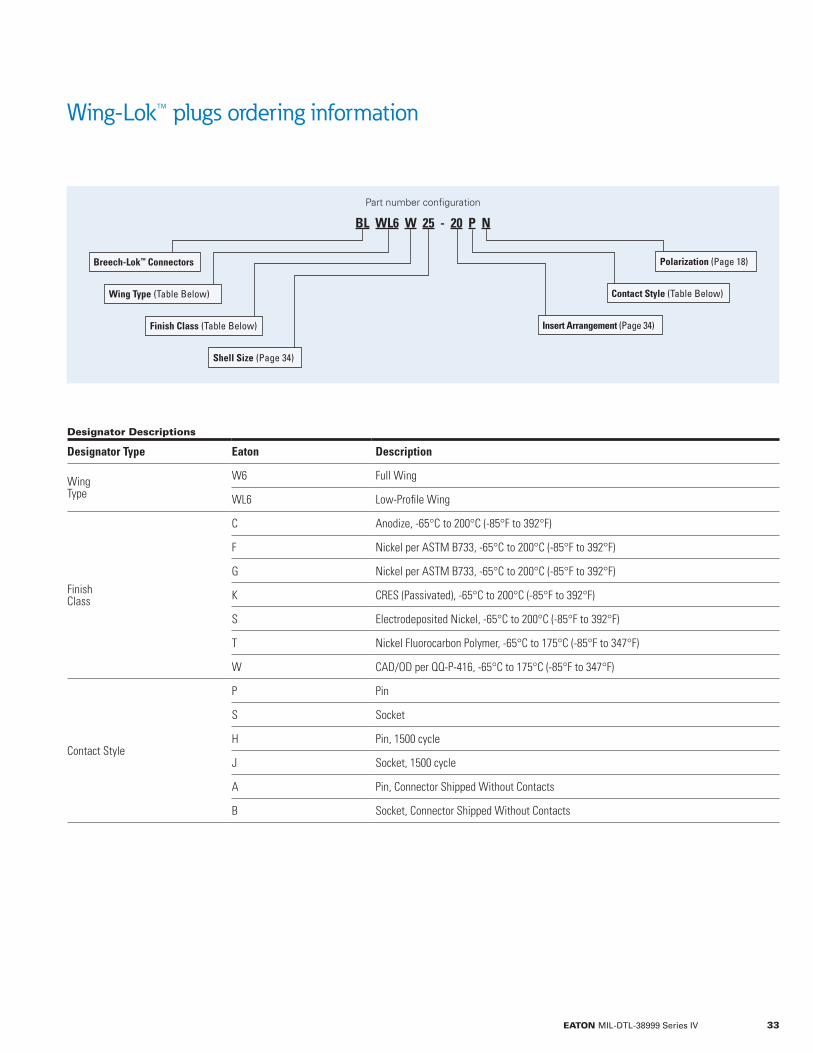
Wing-Lok™ plugs ordering information
Designator Descriptions
Designator Type Eaton Description
WingType
W6 Full Wing
WL6 Low-Profile Wing
FinishClass
C Anodize, -65°C to 200°C (-85°F to 392°F)
F Nickel per ASTM B733, -65°C to 200°C (-85°F to 392°F)
G Nickel per ASTM B733, -65°C to 200°C (-85°F to 392°F)
K CRES (Passivated), -65°C to 200°C (-85°F to 392°F)
S Electrodeposited Nickel, -65°C to 200°C (-85°F to 392°F)
T Nickel Fluorocarbon Polymer, -65°C to 175°C (-85°F to 347°F)
W CAD/OD per QQ-P-416, -65°C to 175°C (-85°F to 347°F)
Contact Style
P Pin
S Socket
H Pin, 1500 cycle
J Socket, 1500 cycle
A Pin, Connector Shipped Without Contacts
B Socket, Connector Shipped Without Contacts
Part number configuration
BL WL6 W 25 - 20 P N
Breech-Lok™ Connectors
Insert Arrangement (Page 34)
Contact Style (Table Below)
Polarization (Page 18)
Wing Type (Table Below)
Finish Class (Table Below)
Shell Size (Page 34)
33EATON MIL-DTL-38999 Series IV

Wing-Lok™ plugs shell & insert configurations
Please contact Eaton to discuss custom shells and inserts
ShellSize
Insert# SR Total #
Contacts# 22D
#20
#16
#12
#8
9 35 M 6 6
9 98 I 3 3
11 2 I 2 2
11 3* II 3 3
11 5 I 5 5
11 35 M 13 13
11 98 I 6 6
11 99 I 7 7
13 4 I 4 4
13 35 M 22 22
13 98 I 10 10
15 5 II 5 5
15 15 I 15 14 1
15 18 I 18 18
15 19 I 19 19
15 35 M 37 37
15 97 I 12 8 4
17 2* M,T 2 2T
17 6 I 6 6
17 8 II 8 8
17 26 I 26 26
17 35 M 55 55
17 98* M,T 26 24 2T
17 99 I 23 21 2
19 3* M,T 3 3T
19 4* M,T 4 4T
19 11 II 11 11
SR = Service Rating, T=Twinax, C=Coax, P=Power* Not a MIL-STD-1560 defined insert arrangement.
ShellSize
Insert# SR Total #
Contacts# 22D
#20
#16
#12
#10
#8
19 18 M,T 18 14 4T
19 32 I 32 32
19 35 M 66 66
21 5* M,T 5 5T
21 11 I 11 11
21 16 II 16 16
21 26* M,T 25 23 2T
21 35 M 79 79
21 39 I 39 37 2
21 41 I 41 41
23 21 II 21 21
23 35 M 100 100
23 53 I 53 53
23 55 I 55 55
23 97 I 16 16
23 99 II 11 11
25 4 I 56 48 8
25 8 M,T 8 8T
25 11 N 11 2 9
25 19 I 19 19
25 20 N,T,C 30 10 13 4C 3T
25 24 I 24 12 12
25 29 I 29 29
25 35 M 128 128
25 43 I 43 23 20
25 46 I,C 46 40 4 2C
25 61 I 61 61
33 54 I 54 30 14 6 4P
33 58 58 34 14 10
34 EATON MIL-DTL-38999 Series IV

Standard-wing plugs mechanical drawings
ShellSize
ØARef
ØBMax
ØCMax
ERef
FRef
U Max Socket
U MaxPin
VThread
9 0.523(13.28)
0.930(23.62)
0.650(16.51)
2.410(61.21)
1.070(27.18)
0.116(2.95)
0.076(1.93) M12x1.0-6g-0.1R
11 0.644(16.36)
1.049(26.64)
0.775(19.69)
2.540(64.52)
1.200(30.48)
0.116(2.95)
0.076(1.93) M15x1.0-6g-0.1R
13 0.765(19.43)
1.206(30.63)
0.901(22.89)
2.690(68.33)
1.340(34.04)
0.117(2.97)
0.077(1.96) M18x1.0-6g-0.1R
15 0.889(22.58)
1.346(34.19)
1.039(26.39)
2.840(72.14)
1.500(38.10)
0.137(3.48)
0.097(2.46) M22x1.0-6g-0.1R
17 1.014(25.76)
1.456(36.98)
1.149(29.18)
2.940(74.68)
1.600(40.64)
0.137(3.48)
0.097(2.46) M25x1.0-6g-0.1R
19 1.094(27.79)
1.581(40.16)
1.275(32.39)
3.060(77.72)
1.720(43.69)
0.158(4.01)
0.118(3.00) M28x1.0-6g-0.1R
21 1.219(30.96)
1.706(43.33)
1.401(35.59)
3.190(81.03)
1.720(43.69)
0.158(4.01)
0.118(3.00) M31x1.0-6g-0.1R
23 1.348(34.24)
1.831(46.51)
1.527(38.79)
3.310(84.07)
1.980(50.29)
0.178(4.52)
0.137(3.48) M34x1.0-6g-0.1R
25 1.475(37.47)
1.956(49.68)
1.649(41.88)
3.440(87.38)
2.100(53.34)
0.178(4.52)
0.137(3.48) M37x1.0-6g-0.1R
33 1.908(48.46)
2.510(63.75)
2.200(55.88)
3.990(101.30)
2.650(67.31)
0.229(5.82)
0.181(4.60) M47x1.0-6g-0.1R
Dimensions are stated as inches (mm).
0.19” Max.(4.83 mm)
0.09 Max.(2.29 mm)1.50” Max.
(38.10 mm)
1.44” Max. Mated (36.58 mm)
1.53” Max. Unmated(38.86 mm)R 0.06” Typ.
(1.52 mm)
R 0.38” Typ.(9.65 mm)
2X 0.25”(6.35 mm)
U Max.
0.45” Max.(11.43 mm)
F E
Blue Color Band
Ø B Ø C
Ø AKey Major
V Thread
35EATON MIL-DTL-38999 Series IV

Low-profile-wing plugs mechanical drawings
ShellSize ØA
ØBMax
ØCMax
DMax
U MaxSocket
U MaxPin
VThread
9 0.523(13.28)
0.923(23.44)
0.650(16.51)
1.423(36.14)
0.116(2.95)
0.076(1.93) M12x1.0-6g-0.1R
11 0.644(16.36)
1.049(26.64)
0.775(19.69)
1.549(39.34)
0.116(2.95)
0.076(1.93) M15x1.0-6g-0.1R
13 0.765(19.43)
1.206(30.63)
0.901(22.89)
1.706(43.33)
0.117(2.97)
0.077(1.96) M18x1.0-6g-0.1R
15 0.889(22.58)
1.346(34.19)
1.039(26.39)
1.846(46.89)
0.137(3.48)
0.097(2.46) M22x1.0-6g-0.1R
17 1.014(25.76)
1.456(36.98)
1.149(29.18)
1.956(49.68)
0.137(3.48)
0.097(2.46) M25x1.0-6g-0.1R
19 1.094(27.79)
1.581(40.16)
1.275(32.39)
2.081(52.86)
0.157(3.99)
0.117(2.97) M28x1.0-6g-0.1R
21 1.219(30.96)
1.706(43.33)
1.401(35.59)
2.206(56.03)
0.157(3.99)
0.117(2.97) M31x1.0-6g-0.1R
23 1.348(34.24)
1.831(46.51)
1.527(38.79)
2.331(59.21)
0.177(4.50)
0.137(3.48) M34x1.0-6g-0.1R
25 1.475(37.47)
1.956(49.68)
1.649(41.88)
2.456(62.38)
0.177(4.50)
0.137(3.48) M37x1.0-6g-0.1R
33 1.908(48.46)
2.513(63.83)
2.200(55.88)
3.013(76.53)
0.233(5.92)
0.181(4.60) M47x1.0-6g-0.1R
Dimensions are stated as inches (mm).
0.09” Max.(2.29 mm)
1.06” Max.(26.92 mm)
0.53” Max.(13.46 mm)
0.19” Min.(4.83 mm)
1.44” Max. (Mated)(36.58 mm)
1.53” Max. (Unmated)(38.86 mm)
R 0.13” Typ.(3.30 mm)
2X 0.24”(6.10 mm)
U Max.
Blue Color Band
Ø DØ CØ B
V Thread
36 EATON MIL-DTL-38999 Series IV
Filtered connectors for noise-sensitive applications
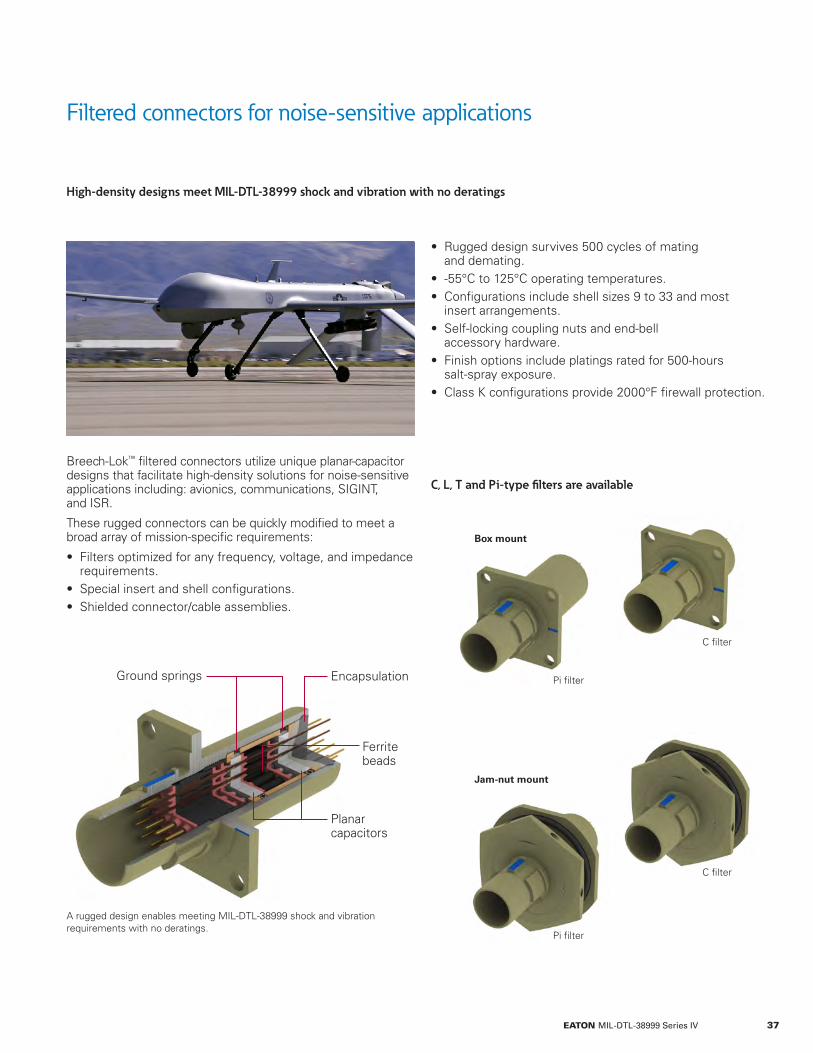
Encapsulation
Ferrite beads
Planar capacitors
A rugged design enables meeting MIL-DTL-38999 shock and vibration requirements with no deratings.
C, L, T and Pi-type filters are available
High-density designs meet MIL-DTL-38999 shock and vibration with no deratings
Breech-Lok™ filtered connectors utilize unique planar-capacitor designs that facilitate high-density solutions for noise-sensitive applications including: avionics, communications, SIGINT, and ISR.
These rugged connectors can be quickly modified to meet a broad array of mission-specific requirements:
• Filters optimized for any frequency, voltage, and impedance requirements.
• Special insert and shell configurations. • Shielded connector/cable assemblies.
• Rugged design survives 500 cycles of mating and demating.
• -55°C to 125°C operating temperatures. • Configurations include shell sizes 9 to 33 and most insert arrangements.
• Self-locking coupling nuts and end-bell accessory hardware.
• Finish options include platings rated for 500-hours salt-spray exposure.
• Class K configurations provide 2000°F firewall protection.
Ground springs
Box mount
Jam-nut mount
Pi filter
Pi filter
C filter
C filter
37EATON MIL-DTL-38999 Series IV

Filtered connectors technical specifications
Materials, Finish, and Mechanical - Contact Eaton to Discuss Additional Finish Classes
Class F Class K Class W
Shell and Coupling Ring Material 2024 Aluminum Corrosion Resistant Stainless Steel 2024 Aluminum
Shell and Coupling Ring Plating Nickel per ASTM B733 Passivated CAD/OD per QQ-P-416
Contact Material & Plating Copper Alloy With Gold Plating, 50 Micro-Inches Minimum - All Finish Classes
Insulator Hard Dielectric Wafer - All Finish Classes
Grommet and Seal Fluorosilicone - All Finish Classes
Grounding Springs Beryllium Copper - All Finish Classes
Mating Life 500 Cycles Minimum - All Finish Classes
Contact Retention Up to 25 Pounds - All Finish Classes
Polarization Per MIL-STD-38999 Series IV; N, A, B, C, D, K, L, M, R, and U - All Finish Classes
Environmental, Shock, Vibration, and EMI/RFI
Class F Class K* Class W
Operating Temperature -55°C to 125°C(-67°F to 257°F)
-55°C to 125°C(-67°F to 257°F)
-55°C to 125°C(-67°F to 257°F)
Sealing Dust (Fine Sand) per MIL-STD-202 and Ice Resistance - All Finish Classes
Corrosion Resistance Withstands 48 Hours Salt Spray Withstands 500 Hours Salt Spray Withstands 500 Hours Salt Spray
Fluid Immersion Various Fuels, Solvents, Coolants, and Oils as per EIA-364-10 - All Finish Classes
Sine Vibration 30g at Ambient Temperature 30g at Ambient Temperature 30g at Ambient Temperature
Random Vibration 50g at Ambient Temperature 50g at Ambient Temperature 50g at Ambient Temperature
Shock 300g +/- 15% Half-Sine-Wave Magnitude for 3 +/- 1mS - All Finish Classes
Emi Leakage Attenuation > 90 dB @ 100MHz> 65 dB @ 10GHz
> 80 dB @ 100MHz> 45 dB @ 10GHz
> 90 dB @ 100MHz> 50 dB @ 10GHz
Shell-to-Shell Conductivity 2.5 Millivolt Maximum Drop 2.5 Millivolt Maximum Drop 1.0 Millivolt Maximum Drop
*Finish Class K configurations provide 2000°F firewall protection for 20 minutes minimum.
38 EATON MIL-DTL-38999 Series IV

Filter performance graphs
Please contact Eaton for L and T filter performance information.
An estimate of insertion loss can be made using the following formula:
IL (dB) = 20 log
Zs = Source impedance in ohms
Z1 = Load impedance in ohms
Zt = Transfer impedance in 50 ohm system
Zs Z1
Zt (Zs + Z1)[ ]1 +
39EATON MIL-DTL-38999 Series IV

Filter types and attenuation ratings
The C filter is a low inductance, feed-thru capacitor. It is used to attenuate high-frequency signals.
The Pi filter consists of two capactive elements and one inductive element. The Pi filter provides better high-frequency performance than the C filter due to sharper roll-off and is designed for high source and load impedances.
Electrical Ratings - Pi and C Filters
Maximum Operating Voltage 200VDC
Current Rating (RF) 3.0 Amps Minimum
IR/DWV 20 Giga Ohms Min @ 500 VDC
Dissipation Factor 2.5% Maximum
Pi Filter C Filter
Capacitance Code C B A Capacitance Code C B A
Capacitance (pF) 53008000
530800
5380 Capacitance (pF) 12000
18000530800
5380
Frequency (MHz) dB Attenuation
dB Attenuation
dB Attenuation Frequency (MHz) dB
AttenuationdB Attenuation
dB Attenuation
Attenuation Minimums per MIL-STD-220 @25°C Without Bias Voltage or Curent
0.1 0 0 0 0.1 -1 0 0
0.5 -3 0 0 0.25 -3 0 0
1 -6 0 0 1 -12 -3 0
5 -32 -3 0 5 -26 -14 -1
10 -47 -8 0 10 -30 -20 -3
50 -81 -42 -3 50 -47 -36 -14
100 -85 -54 -10 100 -56 -45 -24
40 EATON MIL-DTL-38999 Series IV
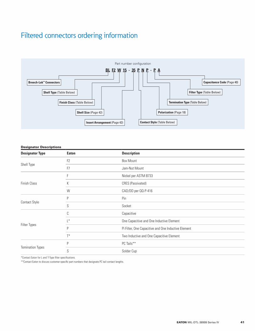
Filtered connectors ordering information
Designator Descriptions
Designator Type Eaton Description
Shell TypeF2 Box Mount
F7 Jam-Nut Mount
Finish Class
F Nickel per ASTM B733
K CRES (Passivated)
W CAD/DD per QQ-P-416
Contact StyleP Pin
S Socket
Filter Types
C Capacitive
L* One Capacitive and One Inductive Element
P Pi Filter, One Capacitive and One Inductive Element
T* Two Inductive and One Capacitive Element
Temination TypesP PC Tails**
S Solder Cup
*Contact Eaton for L and T-Type filter specifications.**Contact Eaton to discuss customer-specific part numbers that designate PC tail contact lengths.
Part number configuration
BL F2 W 15 - 35 P N P - P A
Breech-Lok™ Connectors
Termination Type (Table Below)
Filter Type (Table Below)
Capacitance Code (Page 40)
Shell Type (Table Below)
Finish Class (Table Below)
Shell Size (Page 42) Polarization (Page 18)
Contact Style (Table Below)Insert Arrangement (Page 42)
41EATON MIL-DTL-38999 Series IV
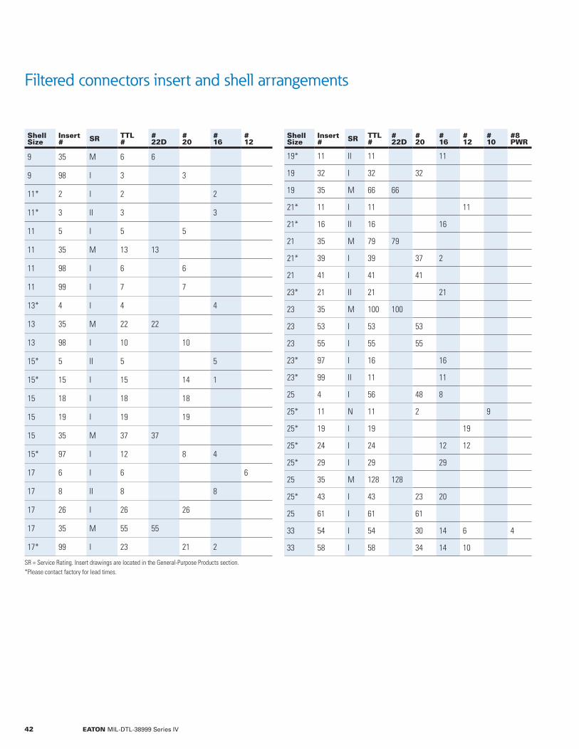
Filtered connectors insert and shell arrangements
ShellSize
Insert# SR TTL
##22D
#20
#16
#12
9 35 M 6 6
9 98 I 3 3
11* 2 I 2 2
11* 3 II 3 3
11 5 I 5 5
11 35 M 13 13
11 98 I 6 6
11 99 I 7 7
13* 4 I 4 4
13 35 M 22 22
13 98 I 10 10
15* 5 II 5 5
15* 15 I 15 14 1
15 18 I 18 18
15 19 I 19 19
15 35 M 37 37
15* 97 I 12 8 4
17 6 I 6 6
17 8 II 8 8
17 26 I 26 26
17 35 M 55 55
17* 99 I 23 21 2
SR = Service Rating. Insert drawings are located in the General-Purpose Products section.*Please contact factory for lead times.
ShellSize
Insert# SR TTL
##22D
#20
#16
#12
#10
#8PWR
19* 11 II 11 11
19 32 I 32 32
19 35 M 66 66
21* 11 I 11 11
21* 16 II 16 16
21 35 M 79 79
21* 39 I 39 37 2
21 41 I 41 41
23* 21 II 21 21
23 35 M 100 100
23 53 I 53 53
23 55 I 55 55
23* 97 I 16 16
23* 99 II 11 11
25 4 I 56 48 8
25* 11 N 11 2 9
25* 19 I 19 19
25* 24 I 24 12 12
25* 29 I 29 29
25 35 M 128 128
25* 43 I 43 23 20
25 61 I 61 61
33 54 I 54 30 14 6 4
33 58 I 58 34 14 10
42 EATON MIL-DTL-38999 Series IV

Box-mount filtered receptacles mechanical drawings
ShellSize
BMax
CMax
DMax
ØEMax
ØMRef
ØPMin
RBSC
SType
U ReferenceSocket Pin
9 0.102(2.59)
0.670(17.02)
1.140(28.96)
0.384(9.75)
0.464(11.79)
0.122(3.10)
0.328(8.33)
0.948(24.08)
0.065(1.65)
0.105(2.67)
11 0.102(2.59)
0.670(17.02)
1.140(28.96)
0.509(12.93)
0.589(14.96)
0.122(3.10)
0.406(10.31)
1.051(26.70)
0.065(1.65)
0.105(2.67)
13 0.102(2.59)
0.670(17.02)
1.140(28.96)
0.634(16.10)
0.720(18.29)
0.122(3.10)
0.453(11.51)
1.146(29.11)
0.065(1.65)
0.105(2.67)
15 0.102(2.59)
0.670(17.02)
1.140(28.96)
0.759(19.28)
0.844(21.44)
0.122(3.10)
0.484(12.31)
1.240(31.50)
0.085(2.16)
0.125(3.18)
17 0.102(2.59)
0.670(17.02)
1.140(28.96)
0.885(22.48)
0.969(24.61)
0.122(3.10)
0.531(13.49)
1.335(33.91)
0.085(2.16)
0.125(3.18)
19 0.102(2.59)
0.670(17.02)
1.140(28.96)
1.009(25.63)
1.088(27.64)
0.122(3.10)
0.578(14.68)
1.461(37.11)
0.105(2.67)
0.145(3.68)
21 0.133(3.38)
0.710(18.03)
1.180(29.97)
1.134(28.80)
1.213(30.81)
0.122(3.10)
0.625(15.88)
1.583(40.21)
0.105(2.67)
0.145(3.68)
23 0.133(3.38)
0.710(18.03)
1.180(29.97)
1.259(31.98)
1.342(34.09)
0.142(3.61)
0.687(17.46)
1.709(43.41)
0.125(3.18)
0.165(4.19)
25 0.133(3.38)
0.710(18.03)
1.180(29.97)
1.384(35.15)
1.469(37.31)
0.142(3.61)
0.750(19.05)
1.835(46.61)
0.125(3.18)
0.165(4.19)
33 0.133(3.38)
0.710(18.03)
1.180(29.97)
1.811(46.00)
1.902(48.31)
0.142(3.61)
1.000(25.40)
2.356(59.84)
0.165(4.19)
0.217(5.51)
Dimensions are stated as inches (mm).
Box mount, C-filter
0.25”(6.35 mm)
0.25”(6.35 mm)
C Max.
B0.81” Max. (20.57 mm)
D Max.
Ø P4 Holes
Ø E
U
Ø MKey Major
R Typ.
R Typ.
S Typ.
91°
Blue Full MateIndicator
0.04” Max.(1.02 mm)
Box mount, PI-filter
B0.81” Max.(20.57 mm)
Ø E
0.04” Max.(1.02 mm)
43EATON MIL-DTL-38999 Series IV

Jam-nut filtered receptacles mechanical drawings
ShellSize
ØBMax
CMax
ØEMax
GThread
H FlatMax
Jam nut D389999/28Dash no.
O-ringMS9068Dash no.
9 1.195(30.35)
0.651(16.54)
0.384(9.75) M17x1.0-6g-0.1R 1.073
(27.25) -2 -018
11 1.520(38.61)
0.942(23.93)
0.509(12.93) M25x1.0-6g-0.1R 1.394
(35.41) -3 -024
13 1.642(41.71)
1.066(27.08)
0.634(16.10) M28x1.0-6g-0.1R 1.520
(38.61) -4 -026
15 1.768(44.91)
1.191(30.25)
0.759(19.28) M31x1.0-6g-0.1R 1.642
(41.71) -5 -028
17 1.957(49.71)
1.321(33.55)
0.885(22.48) M34x1.0-6g-0.1R 1.799
(45.69) -7 -029
19 2.035(51.69)
1.441(36.60)
1.009(25.63) M38x1.0-6g-0.1R 1.909
(48.49) -9 -030
21 2.157(54.79)
1.566(39.78)
1.134(28.80) M41x1.0-6g-0.1R 2.035
(51.69) -10 -031
23 2.283(57.99)
1.691(42.95)
1.259(31.98) M44x1.0-6g-0.1R 2.157
(54.79) -11 -032
25 2.409(61.19)
1.816(46.13)
1.384(35.15) M47x1.0-6g-0.1R 2.283
(57.99) -12 -033
33 3.015(76.58)
2.208(56.08)
1.811(46.00) 2.250-16 UN-2A 2.737
(69.52) N/A -037
Dimensions are stated as inches (mm).
0.37” Max.(9.40 mm)
0.85” Max.(21.59 mm)
0.25”(6.35 mm)
0.25”(6.35)
Jam nut, C-filter
Jam nut, PI-filter
1.12” Max.(28.45 mm)
1.12” Max.(28.45 mm)
BlueFull MateIndicator
91°Ø B
2X H
CFlat
Ø E
Ø E
G Thread
G Thread
44 EATON MIL-DTL-38999 Series IV

Breech-Lok™ hermetic connectors
Fluorosilicone interfacial seal
Hermetic glass seal
Stainless-steel shell
PC tail, solder cup, or eyelet terminations
Harsh-environment design features
Breech-Lok™ hermetic connectors meet all MIL-DTL-38999 Series IV requirements
Breech-Lok™ hermetic connectors are designed for use in pressurized applications and harsh environments. These rugged solutions provide the wide range of features offered by non-hermetic Breech-Lok™ products.
Breech-Lok™ hermetic connectors can be quickly customized to meet a broad array of mission-specific requirements:
• Shell and seal materials optimized for specific environmental requirements.
• Special insert patterns. • Custom connector/cable assemblies.
• No Helium leakage greater than 1 E-7 CC/S per EIA-364-02.
• Rugged design survives 500 cycles of mating and demating.
• Proven performance at -65°C to 200°C operating temperatures.
• Configurations include shell sizes 9 to 33 and most insert arrangements.
• Finish options include 500 hour, salt-spray-rated nickel plating as per ASTM B733.
• Please contact customer service at 800.840.0502 to order products or receive additional information.
Box-mount receptacles
Jam-nut receptacles
Weld-mount receptacles
Solder-mount receptacles
45EATON MIL-DTL-38999 Series IV
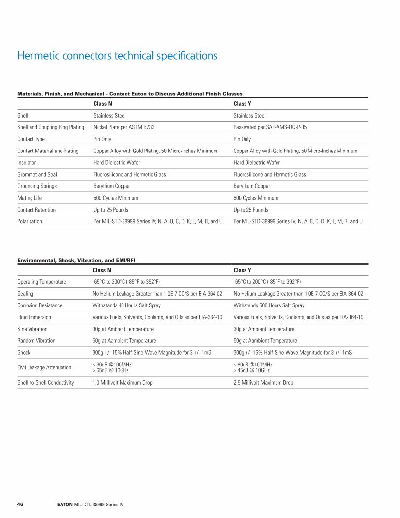
Hermetic connectors technical specifications
Materials, Finish, and Mechanical - Contact Eaton to Discuss Additional Finish Classes
Class N Class Y
Shell Stainless Steel Stainless Steel
Shell and Coupling Ring Plating Nickel Plate per ASTM B733 Passivated per SAE-AMS-QQ-P-35
Contact Type Pin Only Pin Only
Contact Material and Plating Copper Alloy with Gold Plating, 50 Micro-Inches Minimum Copper Alloy with Gold Plating, 50 Micro-Inches Minimum
Insulator Hard Dielectric Wafer Hard Dielectric Wafer
Grommet and Seal Fluorosilicone and Hermetic Glass Fluorosilicone and Hermetic Glass
Grounding Springs Beryllium Copper Beryllium Copper
Mating Life 500 Cycles Minimum 500 Cycles Minimum
Contact Retention Up to 25 Pounds Up to 25 Pounds
Polarization Per MIL-STD-38999 Series IV; N, A, B, C, D, K, L, M, R, and U Per MIL-STD-38999 Series IV; N, A, B, C, D, K, L, M, R, and U
Environmental, Shock, Vibration, and EMI/RFI
Class N Class Y
Operating Temperature -65°C to 200°C (-85°F to 392°F) -65°C to 200°C (-85°F to 392°F)
Sealing No Helium Leakage Greater than 1.0E-7 CC/S per EIA-364-02 No Helium Leakage Greater than 1.0E-7 CC/S per EIA-364-02
Corrosion Resistance Withstands 48 Hours Salt Spray Withstands 500 Hours Salt Spray
Fluid Immersion Various Fuels, Solvents, Coolants, and Oils as per EIA-364-10 Various Fuels, Solvents, Coolants, and Oils as per EIA-364-10
Sine Vibration 30g at Ambient Temperature 30g at Ambient Temperature
Random Vibration 50g at Aambient Temperature 50g at Aambient Temperature
Shock 300g +/- 15% Half-Sine-Wave Magnitude for 3 +/- 1mS 300g +/- 15% Half-Sine-Wave Magnitude for 3 +/- 1mS
EMI Leakage Attenuation > 90dB @100MHz> 65dB @ 10GHz
> 80dB @100MHz> 45dB @ 10GHz
Shell-to-Shell Conductivity 1.0 Millivolt Maximum Drop 2.5 Millivolt Maximum Drop
46 EATON MIL-DTL-38999 Series IV

Hermetic connectors ordering information
Designator Cross References
Designator Type Military Eaton Description
Shell Types
MIL-DTL-38999/45 H1 Solder-Mount Receptacle
MIL-DTL-38999/41 H2 Box-Mount Receptacle
MIL-DTL-38999/48 H4 Weld-Mount Receptacle
MIL-DTL-38999/43 H7 Jam-Nut-Mount Receptacle
Finish ClassesN* N* Nickel Plate, -65°C to 200°C (-85°F to 392°F)
Y* Y* Passivated, -65°C to 200°C (-85°F to 392°F)
Contact Types
C C Pins with PC Tails**
P P Pins with Solder Cups
X X Pins with Eyelets
*N and Y finish classes are QPL certified.**Contact Eaton to discuss customer-specific part numbers that designate PC tail contact lengths.
MIL-DTL part number
D38999/ 43 N B - 35 P N
MIL-DTL-38999 Series IV
Insert Arrangement (Page 48)
Contact Type(Table Below)
Polarization (Page 18)
Shell Type (Table Below)
Finish Class (Table Below)
Shell Size (Page 48)
Eaton part number
BL H7 N 11 - 35 P N
Insert Arrangement (Page 48)
Contact Type(Table Below)
Breech-Lok™ Connectors
Polarization (Page 18)
Shell Type (Table Below)
Finish Class (Table Below)
Shell Size (Page 48)
47EATON MIL-DTL-38999 Series IV

Hermetic connectors shell and insert configurations
Shell-Size Conversions
Military Designation A B C D E F G H J N/A
Shell Size & Eaton Designation 9 11 13 15 17 19 21 23 25 33
ShellSize
Insert# SR Total #
Contacts# 22D
#20
#16
#12
9 35 M 6 6
9 98 I 3 3
11 2 I 2 2
11 3 II 3 3
11 5 I 5 5
11 35 M 13 13
11 98 I 6 6
11 99 I 7 7
13 4 I 4 4
13 35 M 22 22
13 98 I 10 10
15 5 II 5 5
15 15 I 15 14 1
15 18 I 18 18
15 19 I 19 19
15 35 M 37 37
15 97 I 12 8 4
17 6 I 6 6
17 8 II 8 8
17 26 I 26 26
17 35 M 55 55
17 99 I 23 21 2
SR = Service Rating. Insert drawings are located in the General Purpose Products section.
ShellSize
Insert# SR Total #
Contacts# 22D
#20
#16
#12
#10
19 11 II 11 11
19 32 I 32 32
19 35 M 66 66
21 11 I 11 11
21 16 II 16 16
21 35 M 79 79
21 39 I 39 37 2
21 41 I 41 41
23 21 II 21 21
23 35 M 100 100
23 53 I 53 53
23 55 I 55 55
23 97 I 16 16
23 99 II 11 11
25 4 I 56 48 8
25 11 N 11 2 9
25 19 I 19 19
25 24 I 24 12 12
25 29 I 29 29
25 35 M 128 128
25 43 I 43 23 20
25 61 I 61 61
Please contact Eaton to discuss inserts for shell size 33 and custom requirements.
48 EATON MIL-DTL-38999 Series IV

D38999/43 jam-nut hermetic receptacles, Eaton type H7
Jam Nut Receptacles
ShellSize
ØBMax
ØCMax
ØDMax
FRef
ØMMax
ØPMax
RMax
SMax T Thread O-Ring
MS9068
9 0.655(16.64)
0.689(17.50)
1.079(27.41)
0.464(11.79)
0.384(9.75)
0.660(16.76)
0.118(3.00)
0.945(24.00) M17x1.0-6g-0.1R -019
11 0.755(19.18)
0.815(20.70)
1.268(32.21)
0.589(14.96)
0.509(12.93)
0.779(19.79)
0.118(3.00)
1.036(26.31) M20x1.0-6g-0.1R -022
13 0.942(23.93)
1.004(25.50)
1.394(35.41)
0.720(18.29)
0.634(16.1)
0.909(23.09)
0.118(3.00)
1.230(31.24) M25x1.0-6g-0.1R -024
15 1.066(27.08)
1.126(28.60)
1.520(38.61)
0.844(21.44)
0.759(19.28)
1.035(26.29)
0.118(3.00)
1.387(35.23) M28x1.0-6g-0.1R -026
17 1.191(30.25)
1.259(31.98)
1.642(41.71)
0.969(24.61)
0.885(22.48)
1.157(29.39)
0.118(3.00)
1.429(36.30) M32x1.0-6g-0.1R -028
19 1.316(33.43)
1.384(35.15)
1.831(46.51)
1.088(27.64)
1.009(25.63)
1.283(32.59)
0.150(3.81)
1.586(40.28) M35x1.0-6g-0.1R -128
21 1.442(36.63)
1.507(38.28)
1.957(49.71)
1.213(30.81)
1.134(28.80)
1.409(35.79)
0.150(3.81)
1.783(45.29) M38x1.0-6g-0.1R -130
23 1.565(39.75)
1.626(41.30)
2.079(52.81)
1.342(34.09)
1.259(31.98)
1.535(38.99)
0.150(3.81)
1.941(49.30) M41x1.0-6g-0.1R -132
25 1.692(42.98)
1.752(44.5)
2.205(56.01)
1.469(37.31)
1.384(35.15)
1.657(42.09)
0.150(3.81)
2.017(51.23) M44x1.0-6g-0.1R -134
Dimensions are stated as inches (mm).
Jam NutD38999/28
0-Ring MS9068
Ø P2X
0.09” Panel Thickness(2.29 mm)
1.12” Max.(28.40 mm)
1.45” Max.(36.83 mm)
T Thread
Ø M
R
0.33” Max. (8.38 mm)
95°85°
91°
Ø CØ F
Key Major
SRef.
2X D
BFlat
BlueFull MateIndicator
49EATON MIL-DTL-38999 Series IV

D38999/41 box-mount hermetic receptacles, Eaton type H2
Box Mount Receptacles
ShellSize
ØEMax
ØMRef
ØPMin
RBSC
SMax
ØTMax
9 0.384(9.75)
0.464(11.79)
0.122(3.10)
0.328(8.33)
0.945(24.00)
0.496(12.60)
11 0.509(12.93)
0.589(14.96)
0.122(3.10)
0.406(10.31)
1.051(26.70)
0.625(15.88)
13 0.634(16.10)
0.720(18.29)
0.122(3.10)
0.453(11.51)
1.146(29.11)
0.750(19.05)
15 0.759(19.28)
0.844(21.44)
0.122(3.10)
0.484(12.31)
1.240(31.50)
0.906(23.01)
17 0.885(22.48)
0.969(24.61)
0.122(3.10)
0.531(13.49)
1.335(33.91)
1.016(25.81)
19 1.009(25.63)
1.088(27.64)
0.122(3.10)
0.578(14.68)
1.461(37.11)
1.141(28.98)
21 1.134(28.80)
1.213(30.81)
0.122(3.10)
0.625(15.88)
1.583(40.21)
1.266(32.16)
23 1.259(31.98)
1.342(34.09)
0.142(3.61)
0.687(17.46)
1.709(43.41)
1.375(34.93)
25 1.384(35.15)
1.469(37.31)
0.142(3.61)
0.750(19.05)
1.835(46.61)
1.484(37.69)
Dimensions are stated as inches (mm).
0.81” Max.(20.57 mm)
0.39” Max.(9.91 mm)
0.98” Max.(24.89 mm)
0.19” Max. (4.83 mm)
0.09” Max. (2.29 mm)0.03” Max.
(0.76 mm)
Ø E Ø T
Ø MKey Major
RTyp.
RTyp.
STyp.
91°
Ø P4 Holes
BlueMaster Key
BlueFull MateIndicator
50 EATON MIL-DTL-38999 Series IV

D38999/45 solder-mount hermetic receptacles, Eaton type H1
Solder Mount Receptacles
ShellSize
ØDMax
ØEMax
ØMMax
ØSMax
ØTMax
9 0.668(16.97)
0.384(9.75)
0.464(11.79)
0.734(18.64)
0.655(16.64)
11 0.793(20.14)
0.509(12.93)
0.589(14.96)
0.862(21.89)
0.783(19.89)
13 0.919(23.34)
0.634(16.10)
0.720(18.29)
0.988(25.10)
0.909(23.09)
15 1.044(26.52)
0.759(19.28)
0.844(21.44)
1.110(28.19)
1.035(26.29)
17 1.170(29.72)
0.885(22.48)
0.969(24.61)
1.236(31.39)
1.157(29.39)
19 1.294(32.87)
1.009(25.63)
1.088(27.64)
1.330(33.78)
1.251(31.78)
21 1.419(36.04)
1.134(28.80)
1.213(30.81)
1.456(36.98)
1.377(34.98)
23 1.544(39.22)
1.259(31.98)
1.342(34.09)
1.582(40.18)
1.503(38.18)
25 1.669(42.39)
1.384(35.15)
1.469(37.31)
1.704(43.28)
1.629(41.38)
Dimensions are stated as inches (mm).
0.82” Max.(20.83 mm)
0.44” Max.(11.18 mm)
0.98” Max.(24.89 mm)
0.12” Max.(3.05 mm)
0.05” Max. (1.27 mm)
Ø EØ DØ S ØT
Ø MKey Major
91°
BlueFull MateIndicator
BlueMaster Key
51EATON MIL-DTL-38999 Series IV

D38999/48 weld-mount hermetic receptacles, Eaton type H4
Weld Mount Receptacles
ShellSize
ØDMax
ØEMax
ØFRef
ØGMax
ØHMax ØM
9 0.668(16.97)
0.384(9.75)
0.909(23.09)
0.496(12.60)
0.980(24.89)
0.474(12.04)
11 0.793(20.14)
0.509(12.93)
1.035(26.29)
0.625(15.88)
1.106(28.09)
0.589(14.96)
13 0.919(23.34)
0.634(16.10)
1.161(29.49)
0.750(19.05)
1.232(31.29)
0.720(18.29)
15 1.044(26.52)
0.759(19.28)
1.287(32.69)
0.906(23.01)
1.358(34.49)
0.844(21.44)
17 1.170(29.72)
0.885(22.48)
1.374(34.90)
1.016(25.81)
1.445(36.70)
0.969(24.61)
19 1.294(32.87)
1.009(25.63)
1.520(38.61)
1.141(28.98)
1.590(40.39)
1.088(27.64)
21 1.419(36.04)
1.134(28.80)
1.661(42.19)
1.266(32.16)
1.732(43.99)
1.213(30.81)
23 1.544(39.22)
1.259(31.98)
1.827(46.41)
1.375(34.93)
1.898(48.21)
1.342(34.09)
25 1.669(42.39)
1.384(35.15)
1.913(48.59)
1.483(37.67)
1.984(50.39)
1.469(37.31)
Dimensions are stated as inches (mm).
0.82” Max.(20.83 mm)
0.42” Max.(10.67 mm)
0.05” Max.(1.27 mm)
0.98” Max.(24.89 mm)
0.10” Max.(2.54 mm)
Ø EØ DØ F Ø G Ø HØ M
Key Major
91°
BlueFull MateIndicator
Blue Master Key
52 EATON MIL-DTL-38999 Series IV

Printed-circuit-board contact terminations
PC tail contact terminations solder directly to printed circuit boards
Printed circuit board contacts - sockets
• Available for general-purpose connectors in contact sizes 22D through 12. For hermetic and filtered connectors, please refer to the ordering-information table on the next page.
• Contact material: Copper alloy per QQ-C-530. • Contact finish: Gold plate per MIL-G-45204, Type II, Grade C, Class 1 over nickel per QQ-N-290.
• Mating portions of pin per MIL-C-39029/58 and socket per MIL-C-39029/56 as applicable.
• Solders directly to printed-circuit boards using standard through-hole-soldering processes.
Contact Size Socket Part Number A B C
22d 5034-2601-0220 0.026 (0.67) 0.203 (5.16) 0.047 (1.19)
22d 5034-2602-0220 0.020 (0.51) 0.128 (3.25) 0.044 (1.12)
22d 5034-2608-2200 0.019 (0.48) 0.125 (3.18) 0.040 (1.02)
22d 5034-2609-0220 0.026 (0.67) 0.113 (2.87) 0.047 (1.19)
22d 5034-2612-0220 0.026 (0.67) 0.203 (5.16) 0.230 (5.84)
22d 5034-2613-0220 0.020 (0.51) 0.203 (5.16) 0.230 (5.84)
22d 5034-2620-0220 0.020 (0.51) 0.178 (4.52) 0.115 (2.92)
22d 5034-2628-0220 0.017 (0.44) 0.130 (3.30) 0.067 (1.70)
22d 5034-2629-0220 0.026 (0.67) 0.154 (3.91) 0.019 (0.48)
22d 5034-2635-0220 0.019 (0.48) 0.203 (5.16) 0.051 (1.30)
20 5034-2601-0200 0.026 (0.67) 0.203 (5.16) 0.047 (1.19)
20 5034-2602-0200 0.020 (0.51) 0.128 (3.25) 0.044 (1.12)
20 5034-2620-0200 0.020 (0.51) 0.178 (4.52) 0.115 (2.92)
20 5034-2632-0200 0.025 (0.64) 0.215 (5.46) 0.168 (4.27)
16 5034-2620-0160 0.029 (0.75) 0.178 (4.52) 0.115 (2.92)
12 5034-2620-1200 0.029 (0.75) 0.178 (4.52) 0.115 (2.92)
Dimensions are stated as inches (mm).
B C REF.
A DIA
GROMMET FACE
53EATON MIL-DTL-38999 Series IV
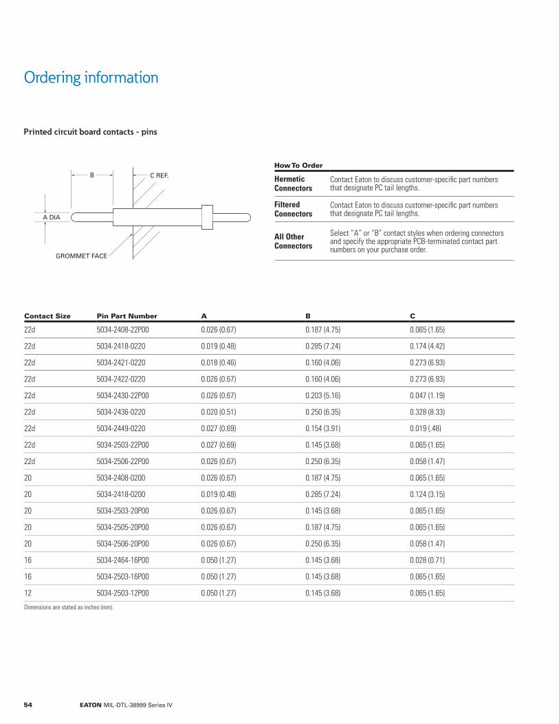
Ordering information
Printed circuit board contacts - pins
How To Order
Hermetic Connectors
Contact Eaton to discuss customer-specific part numbers that designate PC tail lengths.
Filtered Connectors
Contact Eaton to discuss customer-specific part numbers that designate PC tail lengths.
All Other Connectors
Select “A” or “B” contact styles when ordering connectors and specify the appropriate PCB-terminated contact part numbers on your purchase order.
Contact Size Pin Part Number A B C
22d 5034-2408-22P00 0.026 (0.67) 0.187 (4.75) 0.065 (1.65)
22d 5034-2418-0220 0.019 (0.48) 0.285 (7.24) 0.174 (4.42)
22d 5034-2421-0220 0.018 (0.46) 0.160 (4.06) 0.273 (6.93)
22d 5034-2422-0220 0.026 (0.67) 0.160 (4.06) 0.273 (6.93)
22d 5034-2430-22P00 0.026 (0.67) 0.203 (5.16) 0.047 (1.19)
22d 5034-2436-0220 0.020 (0.51) 0.250 (6.35) 0.328 (8.33)
22d 5034-2449-0220 0.027 (0.69) 0.154 (3.91) 0.019 (.48)
22d 5034-2503-22P00 0.027 (0.69) 0.145 (3.68) 0.065 (1.65)
22d 5034-2506-22P00 0.026 (0.67) 0.250 (6.35) 0.058 (1.47)
20 5034-2408-0200 0.026 (0.67) 0.187 (4.75) 0.065 (1.65)
20 5034-2418-0200 0.019 (0.48) 0.285 (7.24) 0.124 (3.15)
20 5034-2503-20P00 0.026 (0.67) 0.145 (3.68) 0.065 (1.65)
20 5034-2505-20P00 0.026 (0.67) 0.187 (4.75) 0.065 (1.65)
20 5034-2506-20P00 0.026 (0.67) 0.250 (6.35) 0.058 (1.47)
16 5034-2464-16P00 0.050 (1.27) 0.145 (3.68) 0.028 (0.71)
16 5034-2503-16P00 0.050 (1.27) 0.145 (3.68) 0.065 (1.65)
12 5034-2503-12P00 0.050 (1.27) 0.145 (3.68) 0.065 (1.65)
Dimensions are stated as inches (mm).
B C REF.
A DIA
GROMMET FACE
54 EATON MIL-DTL-38999 Series IV
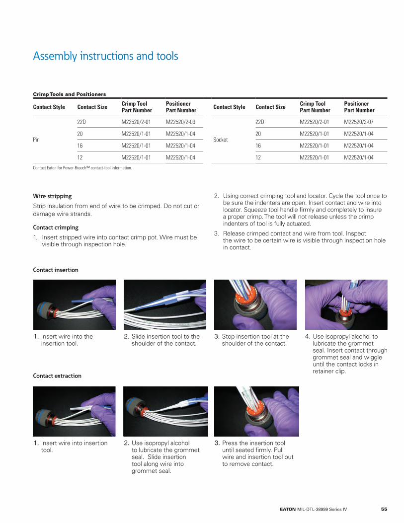
Assembly instructions and tools
Wire stripping
Strip insulation from end of wire to be crimped. Do not cut or damage wire strands.
Contact crimping
1. Insert stripped wire into contact crimp pot. Wire must be visible through inspection hole.
2. Using correct crimping tool and locator. Cycle the tool once to be sure the indenters are open. Insert contact and wire into locator. Squeeze tool handle firmly and completely to insure a proper crimp. The tool will not release unless the crimp indenters of tool is fully actuated.
3. Release crimped contact and wire from tool. Inspect the wire to be certain wire is visible through inspection hole in contact.
Contact insertion
Contact extraction
1. Insert wire into the insertion tool.
1. Insert wire into insertion tool.
2. Slide insertion tool to the shoulder of the contact.
2. Use isopropyl alcohol to lubricate the grommet seal. Slide insertion tool along wire into grommet seal.
3. Stop insertion tool at the shoulder of the contact.
3. Press the insertion tool until seated firmly. Pull wire and insertion tool out to remove contact.
4. Use isopropyl alcohol to lubricate the grommet seal. Insert contact through grommet seal and wiggle until the contact locks in retainer clip.
Crimp Tools and Positioners
Contact Style Contact Size Crimp ToolPart Number
PositionerPart Number Contact Style Contact Size Crimp Tool
Part NumberPositionerPart Number
Pin
22D M22520/2-01 M22520/2-09
Socket
22D M22520/2-01 M22520/2-07
20 M22520/1-01 M22520/1-04 20 M22520/1-01 M22520/1-04
16 M22520/1-01 M22520/1-04 16 M22520/1-01 M22520/1-04
12 M22520/1-01 M22520/1-04 12 M22520/1-01 M22520/1-04
Contact Eaton for Power-Breech™ contact-tool information.
55EATON MIL-DTL-38999 Series IV
Eaton is a registered trademark.
All other trademarks are property of their respective owners.
Eaton1000 Eaton Boulevard Cleveland, OH 44122 United States Eaton.com
Customer Service 750 West Ventura Blvd. Camarillo, CA 93010
© 2014 Eaton All Rights Reserved Printed in USA Publication No. CA800026EN September 2018
For additional information • Visit www.eaton.com/interconnect • Call 805.484.0543 • Email [email protected]