easy roof flat - en.irfts.comen.irfts.com/documentation/noticemontageeasyroof_flat_en.pdf · *...
TRANSCRIPT

Info
rmat
ion
and
visu
als n
on-c
ontr
actu
al. S
ubje
ct to
tech
nica
l mod
ifica
tions
with
out n
otic
e.
This document is the property of IRFTS. It shall not be reproduced or shared with third parties without IRFTS' agreement
ASSEMBLY INSTRUCTIONS
For all LANDSCAPE-orientated framed modules
INS-IN02-180726 Version 1.0 - 24-04-18
EASY ROOF FLAT PV FIXING SYSTEM FOR FLAT ROOF
Document validated by ENQUETE TECHNIQUE NOUVELLE No. L18.3628
The EASY ROOF FLAT system is insured provide that the modules have IEC 61215 and IEC 61730 approvals
Module compatibilities: www.irfts.com

Info
rmat
ion
and
visu
als n
on-c
ontr
actu
al. S
ubje
ct to
tech
nica
l mod
ifica
tions
with
out n
otic
e.
This document is the property of IRFTS. It shall not be reproduced or shared with third parties without IRFTS' agreement 2 EASY ROOF FLAT
FITTING INSTRUCTIONS Before installing the EASY ROOF FLAT base, spread footings must be available as stipulated in DTU43.1 SAFETY INSTRUCTIONS The planning, fitting and commissioning of the installation must only be carried out by qualified personnel. Incorrect execution can result in damage to the system and can put lives in danger. It is imperative to comply with national and local construction standards, miscellaneous regulations and environmental protection directives in force*. Safety regulations and accident prevention instructions must be observed. Appropriate fall prevention devices must be used for all work performed at height. Before assembly, it is your responsibility to check the amount of ballast, the load capacity of the roof and the compatibility of the installation with the various roof coatings/insulations. Before assembly, check that you have the up-to-date version of the assembly instructions on our website: http://fr.irfts.com/supports/. Throughout the installation operation, make sure that at least one copy of the installation instruction manual is available on site. Please take into account the module manufacturer’s assembly instructions. To remove the system, apply the installation procedure in reverse. Compliance with the safety and operating instructions for the system entitles you to a ten-year product warranty**. ASSEMBLY ADVICE This system can be installed on all flat horizontal surfaces, mainly common terrace roofs with a bearing structure of sufficient load capacity and a roof slope of up to 5%. The distributed surface load of the installation with its ballast must be no more than the residual load capacity of the building. As a rule, all the technical aspects of the support, roof and building must be checked before assembly. When in doubt, a building professional must be consulted. The process can only be implemented on roofing with a technical opinion or a technical application document that allows the installation of technical components, in accordance with DTU43.1 or DTU43.11. In particular, the insulation on the underside of the damp proof course must be at least Class C in accordance with the CSTB Technical Guide UEAtc (1) for the approval of sealing support insulating systems for flat and sloping roofs (Specification 2662_V2 - July 2010). * Compliance with NF C15-712 is especially important in France. ** IRFTS fitter training information.

Info
rmat
ion
and
visu
als n
on-c
ontr
actu
al. S
ubje
ct to
tech
nica
l mod
ifica
tions
with
out n
otic
e.
This document is the property of IRFTS. It shall not be reproduced or shared with third parties without IRFTS' agreement 3 EASY ROOF FLAT
In addition, in accordance with the provisions of §9.1 of DTU43.1 (Roofs receiving permanent heavy equipment, regardless of the destination), the connections between equipment and the terraced roof must allow servicing and overhaul of sealing structures. The EASY ROOF FLAT process is designed for easy removal (and/or) transport without the need for lifting machinery (the ballast must never be more than 67 kg). Every component (KITS with reference bases ASM0P0483A) will rest on an appropriate resilient material (expanded or extruded polystyrene) or on the footing provided by IRFTS. These spread components (intended to prevent any pinching of the damp proof course) will be sized as follows: The smallest support dimension is no less than 0.40 m. The pressure at the sealing coating is limited in the conditions below. The maximum pressure under every slab must be calculated by the company in charge of equipment implementation (in accordance with §3.1 ag) of FD P 84-204-3]. The project manager verifies the compatibility between the calculated pressures resulting from the equipment and the allowable pressures (in accordance with FD P 84-204-3). For a coating under reversed insulation, the allowable pressure is the smaller of the following two values:
The one indicated in the table below, The one indicated in the Technical Application Document for the insulating panel.
For a sealing coating on insulating panel support, the allowable pressure is the smaller of the following three values:
- The one indicated in the table below (caution: remember (see §6.5.1 of DTU43.1) that Class I2 SBS elastomer bilayer coatings are not permitted on insulating panel supports). - The one indicated for this use in the application documents for sealing support insulating panels other than cork-based supports, - 4 kPa (0.04 daN/cm2) for sealing coatings applied to insulating panels in expanded agglomerated cork.
Table (DTU43.1 extract): Allowable pressure on masonry support coating
Info
rmat
ion
and
visu
als n
on-c
ontr
actu
al. S
ubje
ct to
tech
nica
l mod
ifica
tions
with
out n
otic
e.
This document is the property of IRFTS. It shall not be reproduced or shared with third parties without IRFTS' agreement 4 EASY ROOF FLAT
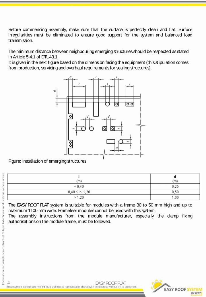
Before commencing assembly, make sure that the surface is perfectly clean and flat. Surface irregularities must be eliminated to ensure good support for the system and balanced load transmission. The minimum distance between neighbouring emerging structures should be respected as stated in Article 5.4.1 of DTU43.1. It is given in the next figure based on the dimension facing the equipment (this stipulation comes from production, servicing and overhaul requirements for sealing structures). Figure: Installation of emerging structures The EASY ROOF FLAT system is suitable for modules with a frame 30 to 50 mm high and up to maximum 1100 mm wide. Frameless modules cannot be used with this system. The assembly instructions from the module manufacturer, especially the clamp fixing authorisations on the module frame, must be followed.

Info
rmat
ion
and
visu
als n
on-c
ontr
actu
al. S
ubje
ct to
tech
nica
l mod
ifica
tions
with
out n
otic
e.
This document is the property of IRFTS. It shall not be reproduced or shared with third parties without IRFTS' agreement
Contents
5
1. Parts list ........................................................................................................................................................... 6
1.1. Parts supplied in the kit ........................................................................................................................... 6 1.2. Parts not supplied in the kit ..................................................................................................................... 6 1.3. List of tools required for assembly .......................................................................................................... 6 1.4. Presentation of parts ............................................................................................................................. 7-8
2. Part markings .................................................................................................................................................. 9
3. Illustration of possible orientations .............................................................................................................. 10
4. Photovoltaic field meterage .......................................................................................................................... 11
5. EASY ROOF FLAT system assembly instruction .......................................................................................... 12-16
5.1. Feet onto base assembly ................................................................................................................... 12-13 5.2. Adjusting and fitting to the roof ........................................................................................................ 13-16
6. Earthing ...................................................................................................................................................... 17-18 6.1 Earthing instruction ........................................................................................................................ ........ 17 6.2 Fixing the trunking .......................................................................................................................... ........ 18
7. Other possible fixings for the system …………………………………………………………………………………… ....... …….. . 19-23 7.1 Fixing to rail .......................................................................................................................... ... 19-21 7.2 Fixing to concrete .................................................................................................................. .... 22-23
EASY ROOF FLAT

Info
rmat
ion
and
visu
als n
on-c
ontr
actu
al. S
ubje
ct to
tech
nica
l mod
ifica
tions
with
out n
otic
e.
This document is the property of IRFTS. It shall not be reproduced or shared with third parties without IRFTS' agreement
EASY ROOF FLAT parts list
(1) Ballast as per table below:
Number Qty. Description Item code1 FLA 2 SET BASE&SUPPORT 125/250 ASM0P0571A
1 2 FLA SET BASE&SUPPORT 125/250 ASM0P0483A2 FLA EAVE SUPPORT 125 ASM0P0471A3 FLA RIDGE SUPPORT 250 ASM0P0472A4 2 FLA BASE ASMP0P0413A
5 PRT0P00534A
Parts supplied in the kit
Optional parts FLA PROTECTION MAT 6*300*850
Number Description a Ballast slab (1)
Parts not supplied in the kit
1) 1.1)
1.2)
6 EASY ROOF FLAT
1.3) List of tools required for assembly
Hex key no. 5 and 6
Calculation as per Eurocodes 1 NF EN 1991 SOUTH EAST-WEST
Wind area 1 2 3 4 1 2 3 4
Height
3 m 27 32 38 44 22 26 30 35
6 m 29 35 41 47 24 28 33 38
9 m 34 41 48 56 28 33 39 45
12 m 38 46 54 62 31 37 43 50
15 m 42 49 58 67 33 40 46 54 Ballast for one module in kg

Info
rmat
ion
and
visu
als n
on-c
ontr
actu
al. S
ubje
ct to
tech
nica
l mod
ifica
tions
with
out n
otic
e.
This document is the property of IRFTS. It shall not be reproduced or shared with third parties without IRFTS' agreement
Presentation of parts
2
3
1.4)
7 EASY ROOF FLAT
1
3

Info
rmat
ion
and
visu
als n
on-c
ontr
actu
al. S
ubje
ct to
tech
nica
l mod
ifica
tions
with
out n
otic
e.
This document is the property of IRFTS. It shall not be reproduced or shared with third parties without IRFTS' agreement
Presentation of parts 1.4)
8 EASY ROOF FLAT
5
146 mm
321 mm
202 mm 52 mm
16 mm
850 mm
300 mm Th.: 6 mm
α°
1
1
3
3
2
2
Position α° 1 10 2 12 3 14
Info
rmat
ion
and
visu
als n
on-c
ontr
actu
al. S
ubje
ct to
tech
nica
l mod
ifica
tions
with
out n
otic
e.
This document is the property of IRFTS. It shall not be reproduced or shared with third parties without IRFTS' agreement
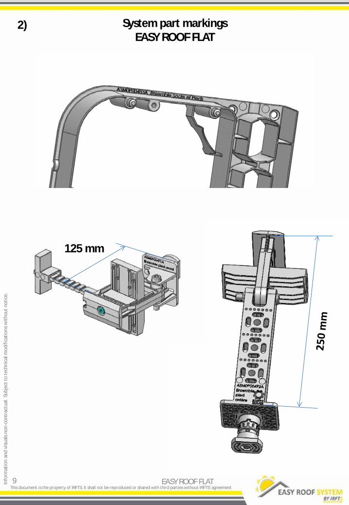
System part markings EASY ROOF FLAT
2)
9 EASY ROOF FLAT
125 mm

Info
rmat
ion
and
visu
als n
on-c
ontr
actu
al. S
ubje
ct to
tech
nica
l mod
ifica
tions
with
out n
otic
e.
This document is the property of IRFTS. It shall not be reproduced or shared with third parties without IRFTS' agreement
Illustration of possible orientations
Facing South
3)
10 EASY ROOF FLAT
Facing East-West
Independent line assembly Interline assembly
Independent line assembly Interline assembly
Info
rmat
ion
and
visu
als n
on-c
ontr
actu
al. S
ubje
ct to
tech
nica
l mod
ifica
tions
with
out n
otic
e.
This document is the property of IRFTS. It shall not be reproduced or shared with third parties without IRFTS' agreement
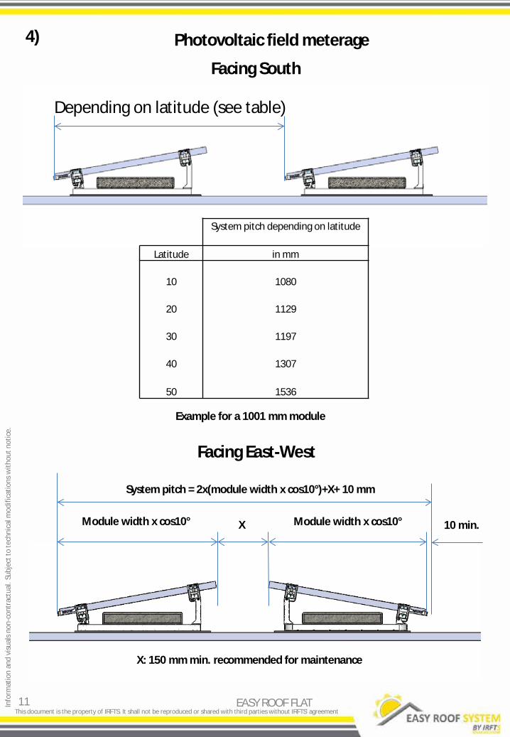
Photovoltaic field meterage 4)
11 EASY ROOF FLAT
Facing South
Facing East-West
Depending on latitude (see table)
X Module width x cos10° Module width x cos10°
System pitch = 2x(module width x cos10°)+X+ 10 mm
10 min.
X: 150 mm min. recommended for maintenance
Example for a 1001 mm module
System pitch depending on latitude
Latitude in mm
10 1080
20 1129
30 1197
40 1307
50 1536

Info
rmat
ion
and
visu
als n
on-c
ontr
actu
al. S
ubje
ct to
tech
nica
l mod
ifica
tions
with
out n
otic
e.
This document is the property of IRFTS. It shall not be reproduced or shared with third parties without IRFTS' agreement
Feet onto base assembly
5)
12 EASY ROOF FLAT
5.1)
Mount the bottom solar end stop on the front foot (optional)
Turn the foot socket to insert it into the base
EASY ROOF FLAT system assembly instruction

Info
rmat
ion
and
visu
als n
on-c
ontr
actu
al. S
ubje
ct to
tech
nica
l mod
ifica
tions
with
out n
otic
e.
This document is the property of IRFTS. It shall not be reproduced or shared with third parties without IRFTS' agreement
5.1)
13 EASY ROOF FLAT
Turn the feet a quarter turn
Tip the front foot to access its fixing screw.
Tighten the feet onto the base (torque: 5 Nm)

Info
rmat
ion
and
visu
als n
on-c
ontr
actu
al. S
ubje
ct to
tech
nica
l mod
ifica
tions
with
out n
otic
e.
This document is the property of IRFTS. It shall not be reproduced or shared with third parties without IRFTS' agreement
Adjusting and fitting to the roof 5.2)
14 EASY ROOF FLAT
Slope the feet 10°
Fit the assembly onto the footing
Fit the ballast onto the base
630 mm
80 mm 190 mm
X
Y
Squared slab in kg XxX/Y 40 mm 45 mm 50 mm
300 mm 8.6 9.6 10.7 350 mm 11.7 13.2 14.6 400 mm 15.3 17.2 19.1 450 mm 19.3 21.8 24.2

Info
rmat
ion
and
visu
als n
on-c
ontr
actu
al. S
ubje
ct to
tech
nica
l mod
ifica
tions
with
out n
otic
e.
This document is the property of IRFTS. It shall not be reproduced or shared with third parties without IRFTS' agreement
Adjusting and fitting to the roof 5.2)
15 EASY ROOF FLAT
Ballast 300x300x40 (5 max.)
Ballast 300x300x50 (3 max.)
Ballast 350x350x40 (3 max.)
Ballast 350x350x45 (3 max.)
Ballast 400x400x40 (3 max.)
Ballast 400x400x50 (2 max.)
Ballast 450x450x40 (3 max.)
Ballast 450x450x50 (2 max.)
Ballast 300x300x45 (5 max.)
Ballast 350x350x50 (2 max.)
Ballast 400x400x45 (3 max.) Ballast 450x450x45 (2 max.)

Info
rmat
ion
and
visu
als n
on-c
ontr
actu
al. S
ubje
ct to
tech
nica
l mod
ifica
tions
with
out n
otic
e.
This document is the property of IRFTS. It shall not be reproduced or shared with third parties without IRFTS' agreement
5.2)
16 EASY ROOF FLAT
Space the two bases according to the length of the PV module
Clamp the panel using the screws on each foot (tightening torque 6 Nm)

Info
rmat
ion
and
visu
als n
on-c
ontr
actu
al. S
ubje
ct to
tech
nica
l mod
ifica
tions
with
out n
otic
e.
This document is the property of IRFTS. It shall not be reproduced or shared with third parties without IRFTS' agreement
Earthing instruction 6.1)
17 EASY ROOF FLAT
Each rear foot must be earthed using EASY GROUNDING
EASY GROUNDING
Connect the end panels to the earth
To avoid breaking the earth continuity, IRFTS only permits one panel per line to be dismantled at once unless they are adjacent
End panels
one earthing part on every module
one earthing part every two modules
There are two ways of wiring the PV field earth, depending on the regulations in force in the country.
Possibility 1 (France)
Possibility 2

Info
rmat
ion
and
visu
als n
on-c
ontr
actu
al. S
ubje
ct to
tech
nica
l mod
ifica
tions
with
out n
otic
e.
This document is the property of IRFTS. It shall not be reproduced or shared with third parties without IRFTS' agreement
Fixing the trunking 6.2)
18 EASY ROOF FLAT
Three ways of fixing a cable run trunking
Possible fixing

Info
rmat
ion
and
visu
als n
on-c
ontr
actu
al. S
ubje
ct to
tech
nica
l mod
ifica
tions
with
out n
otic
e.
This document is the property of IRFTS. It shall not be reproduced or shared with third parties without IRFTS' agreement
Fixing to rail 7.1)
19 EASY ROOF FLAT
Number Description Item code6 FLA RAIL STD 3000 PRT0P00476A7 FLA SPLICED RAIL STD 150 PRT0P00477A
Parts supplied in the kit
Representation of parts
6
7

Info
rmat
ion
and
visu
als n
on-c
ontr
actu
al. S
ubje
ct to
tech
nica
l mod
ifica
tions
with
out n
otic
e.
This document is the property of IRFTS. It shall not be reproduced or shared with third parties without IRFTS' agreement
Fixing to rail 7.1)
20 EASY ROOF FLAT
The centre between distances of the posts depthwise on the installation will be as per the tables on page 11.
The centre between distances of the posts widthwise will be equal to the panel length + 16 mm.
See table on page 11
Panel length + 16 mm
The rail is fixed to metal legs (stainless steel A304L or aluminium ENW6063 T66) using A2 stainless steel bolts (not supplied by IRFTS, size decided by the fitter). The fitter is responsible for sizing this rail/post interface: The tensile loads to be considered are taken from the table on page 6 of this document. Any momentary effects (induced by the altitude of the PV field in relation to the sealing level) are decided by the project management and/or the contractor that has to size these components. In this case, please refer to §5.4.2 of DTU43.1 which states in particular that if the equipment can be dismantled when overhauling the sealing (the case here as each component weighs less than 90 kg), the height between the sealing plane and the underside of the rails can be reduced to 0.30 m. The minimum value required (clearance under equipment) is 300 mm

Info
rmat
ion
and
visu
als n
on-c
ontr
actu
al. S
ubje
ct to
tech
nica
l mod
ifica
tions
with
out n
otic
e.
This document is the property of IRFTS. It shall not be reproduced or shared with third parties without IRFTS' agreement
Fixing to rail 7.1)
21 EASY ROOF FLAT
Slide the feet 125 and 250 onto the rail.
= =
Tighten the feet onto the rails as per the recommendations.

Info
rmat
ion
and
visu
als n
on-c
ontr
actu
al. S
ubje
ct to
tech
nica
l mod
ifica
tions
with
out n
otic
e.
This document is the property of IRFTS. It shall not be reproduced or shared with third parties without IRFTS' agreement
Fixing to concrete 7.2)
22 EASY ROOF FLAT
Detach the base fixings and insert them in the closest feet cells.
Use min. M6 fixings for concrete.
Fixing the base
Example of fixing position

Info
rmat
ion
and
visu
als n
on-c
ontr
actu
al. S
ubje
ct to
tech
nica
l mod
ifica
tions
with
out n
otic
e.
This document is the property of IRFTS. It shall not be reproduced or shared with third parties without IRFTS' agreement
Fixing to concrete 7.2)
23 EASY ROOF FLAT
Styrodur 40 mm or IRFTS membrane
Sealing membrane
Concrete post
In this assembly, it is important for the pins (and the drillholes in the concrete slabs) to be no longer than the thickness of the spread slab, to avoid disturbing the damp proof course. The fitter will use the calculations on the ballast values in the table on page 6 of this document as a basis: the spread slab + pin system must compensate for the upward forces.
Concrete post
Fixing pin
Styrodur 40 mm or IRFTS membrane