easwari engineering college, ramapuram · pdf fileengineering college ... state the degree of...
TRANSCRIPT

MUTHUKUMAR.P/Asst.Prof./CIVIL-III Page 1
MAHALAKSHMI ENGINEERING COLLEGE
TIRUCHIRAPALLI - 621213.
QUESTION WITH ANSWERS
DEPARTMENT : CIVIL SEMESTER: V
SUB.CODE/ NAME: CE 2252 / Strength of Materials
UNIT– 2 INDETERMINATE BEAMS
1. Define statically indeterminate beams.
If the numbers of reaction components are more than the conditions equations, the structure is
defined as statically indeterminate beams.
E = R – r
E = Degree of external redundancy
R = Total number of reaction components
r = Total number of condition equations available.
A continuous beam is a typical example of externally indeterminate structure.
2. State the degree of indeterminacy in propped cantilever.
For a general loading, the total reaction components (R) are equal to (3+2) =5,
While the total number of condition equations (r) are equal to 3. The beam is statically
indeterminate, externally to second degree. For vertical loading, the beam is statically determinate
to single degree.
E = R – r
= 5 – 3 = 2
3. State the degree of indeterminacy in a fixed beam.
For a general system of loading, a fixed beam is statically indeterminate to third degree. For
vertical loading, a fixed beam is statically indeterminate to second degree.
E = R – r
For general system of loading:
R = 3 + 3 and r = 3
E = 6-3 = 3
For vertical loading:
R = 2+2 and r = 2
E = 4 – 2 = 2
MUTHUKUMAR.P/Asst.Prof./CIVIL-III Page 2
4. State the degree of indeterminacy in the given beam.
The beam is statically indeterminate to third degree of general system of loading.
R = 3+1+1+1 = 6
E = R-r
= 6-3 = 3
5. State the degree of indeterminacy in the given beam.
The beam is statically determinate. The total numbers of condition equations are equal to 3+2 = 5.
Since, there is a link at B. The two additional condition equations are at link.
E = R-r
= 2+1+2-5
= 5-5
E = 0
6. State the methods available for analyzing statically indeterminate structures.
i. Compatibility method
ii. Equilibrium method
7. Write the expression fixed end moments and deflection for a fixed beam carrying point
load at centre.
EI
WLy
WLMM BA
192
83
max
8. Write the expression fixed end moments and deflection for a fixed beam carrying
eccentric point load.
)(3 3
33
max
2
2
2
2
loadtheunderEIL
bWay
L
bWaM
L
WabM
B
A
9. Write the expression fixed end moments for a fixed due to sinking of support.
2
6
L
EIMM BA
10. State the Theorem of three moments. (AUC Nov/Dec 2013) (AUC Apr/May 2011)
Theorem of three moments:
It states that “If BC and CD are only two consecutive span of a continuous beam subjected to an
external loading, then the moments MB, MC and MD at the supports B, C and D are given by
MUTHUKUMAR.P/Asst.Prof./CIVIL-III Page 3
2
_
22
1
1
_
12211
66.)(2
L
xa
L
xaLMLLMLM DCB
Where
MB = Bending Moment at B due to external loading
MC = Bending Moment at C due to external loading
MD = Bending Moment at D due to external loading
L1 = length of span AB
L2 = length of span BC
a1 = area of B.M.D due to vertical loads on span BC
a2 = area of B.M.D due to vertical loads on span CD
1
_
x = Distance of C.G of the B.M.D due to vertical loads on BC from B
2
_
x = Distance of C.G of the B.M.D due to vertical loads on CD from D.
11. What are the fixed end moments for a fixed beam of length ‘L’ subjected to a
concentrated load ‘w’ at a distance ‘a’ from left end?
(AUC Nov/Dec – 2004)
(AUC Apr/May 2010)
Fixed End Moment:
2
2
2
2
L
WabM
L
WabM
B
A
12. Explain the effect of settlement of supports in a continuous beam. (Nov/Dec 2003)
Due to the settlement of supports in a continuous beam, the bending stresses will alters
appreciably. The maximum bending moment in case of continuous beam is less when compare to the
simply supported beam.
13. What are the advantages of Continuous beams over Simply Supported beams?
(i)The maximum bending moment in case of a continuous beam is much less than in case of a
simply supported beam of same span carrying same loads.
(ii) In case of a continuous beam, the average B.M is lesser and hence lighter materials of
construction can be used it resist the bending moment.
14. A fixed beam of length 5m carries a uniformly distributed load of 9 kN/m run over the
entire span. If I = 4.5x10⁻⁴ m4 and E = 1x10⁷ kN/m2, find the fixing moments at the ends
and deflection at the centre.
Solution:
Given:
L = 5m
W = 9 kN/m2 , I = 4.5x10⁻⁴ m4 and E = 1x10⁷ kN/m2
(i) The fixed end moment for the beam carrying udl:
MUTHUKUMAR.P/Asst.Prof./CIVIL-III Page 4
MA = MB = 12
2WL
= KNmx
75.1812
)5(9 2
(ii) The deflection at the centre due to udl:
mmxxxx
xy
EI
WLy
c
c
254.3105.4101384
)5(9
384
47
4
4
Deflection is in downward direction.
15. A fixed beam AB, 6m long is carrying a point load of 40 kN at its center. The M.O.I of the
beam is 78 x 106 mm4 and value of E for beam material is 2.1x10⁵ N/mm2. Determine (i)
Fixed end moments at A and B.
Solution:
Fixed end moments:
8
WLMM BA
kNmx
MM BA 5.378
650
16. A fixed beam AB of length 3m is having M.O.I I = 3 x 106 mm4 and value of E for beam
material is 2x10⁵ N/mm2. The support B sinks down by 3mm. Determine (i) fixed end
moments at A and B.
Solution:
Given:
L = 3m = 3000mm
I = 3 x 106 mm4
E = 2x10⁵ N/mm2
= 3mm
2
6
L
EIMM BA
=2
65
)3000(
31031026 xxxxx
=12x105 N mm = 12 kN m.
17. A fixed beam AB, 3m long is carrying a point load of 45 kN at a distance of 2m from A. If
the flexural rigidity (i.e) EI of the beam is 1x10⁴kNm2. Determine (i) Deflection under the
Load.
Solution:
L = 3m
W = 45 Kn EI = 1x10⁴ kNm2
MUTHUKUMAR.P/Asst.Prof./CIVIL-III Page 5
Deflection under the load:
In fixed beam, deflection under the load due to eccentric load
3
33
3EIL
bWayC
mmy
my
xxx
xxy
C
C
C
444.0
000444.0
)3(1013
)1()2(4524
33
The deflection is in downward direction.
18. A fixed beam of 5m span carries a gradually varying load from zero at end A to 10 kN/m
at end B. Find the fixing moment and reaction at the fixed ends.
Solution:
Given:
L = 5m
W = 10 kN/m
(i) Fixing Moment:
2030
22 WLMand
WLM BA
MA = kNm33.830
250
30
)5(10 2
kNmMB 5.1220
250
20
)5(10 2
(ii) Reaction at support:
20
7
20
3 WLRand
WLR BA
kNR
kNR
B
A
5.1720
350
20
5*10*7
5.720
150
20
5*10*3
MUTHUKUMAR.P/Asst.Prof./CIVIL-III Page 6
19. A cantilever beam AB of span 6m is fixed at A and propped at B. The beam carries a udl
of 2kN/m over its whole length. Find the reaction at propped end. (May /.June2012)
Solution:
Given:
L=6m, w =2 kN/m
Downward deflection at B due to the udl neglecting prop reaction P,
EI
wlyB
8
4
Upward deflection at B due to the prop reaction P at B neglecting the udl,
EI
PlyB
3
3
Upward deflection = Downward deflection
EI
Pl
3
3
EI
wl
8
4
P = 3WL/8 = 3*2*6/8 =4.5 Kn
19. Give the procedure for analyzing the continuous beams with fixed ends using three moment
equations?
The three moment equations, for the fixed end of the beam, can be modified by
imagining a span of length l 0 and moment of inertia, beyond the support the and applying the
theorem of three moments as usual.
20. Define Flexural Rigidity of Beams.
The product of young’s modulus (E) and moment of inertia (I) is called Flexural
Rigidity (EI) of Beams. The unit is N mm2.
21. What is a fixed beam? (AUC Apr/May 2011)
A beam whose both ends are fixed is known as a fixed beam. Fixed beam is also called as
built-in or encaster beam. Incase of fixed beam both its ends are rigidly fixed and the slope and
deflection at the fixed ends are zero.
23. What are the advantages of fixed beams?
(i) For the same loading, the maximum deflection of a fixed beam is less than that of a
simply supported beam.
(ii) For the same loading, the fixed beam is subjected to lesser maximum bending
moment.
(iii) The slope at both ends of a fixed beam is zero.
(iv) The beam is more stable and stronger.
24. What are the disadvantages of a fixed beam?
(i) Large stresses are set up by temperature changes.
(ii) Special care has to be taken in aligning supports accurately at the same lavel.
(iii) Large stresses are set if a little sinking of one support takes place.
(iv) Frequent fluctuations in loadingrender the degree of fixity at the ends very uncertain.
25. Define: Continuous beam.
A Continuous beam is one, which is supported on more than two supports. For usual
loading on the beam hogging ( - ive ) moments causing convexity upwards at the supports and
sagging ( + ve ) moments causing concavity upwards occur at mid span.
MUTHUKUMAR.P/Asst.Prof./CIVIL-III Page 7
26. What is mean by prop? . (AUC Nov/Dec 2012)
When a beam or cantilever carries some load , maximum deflection occurs at the free
end . the deflection can be reduced by providing vertical support at these points or at any suitable
points.
(PART B 16 Marks)
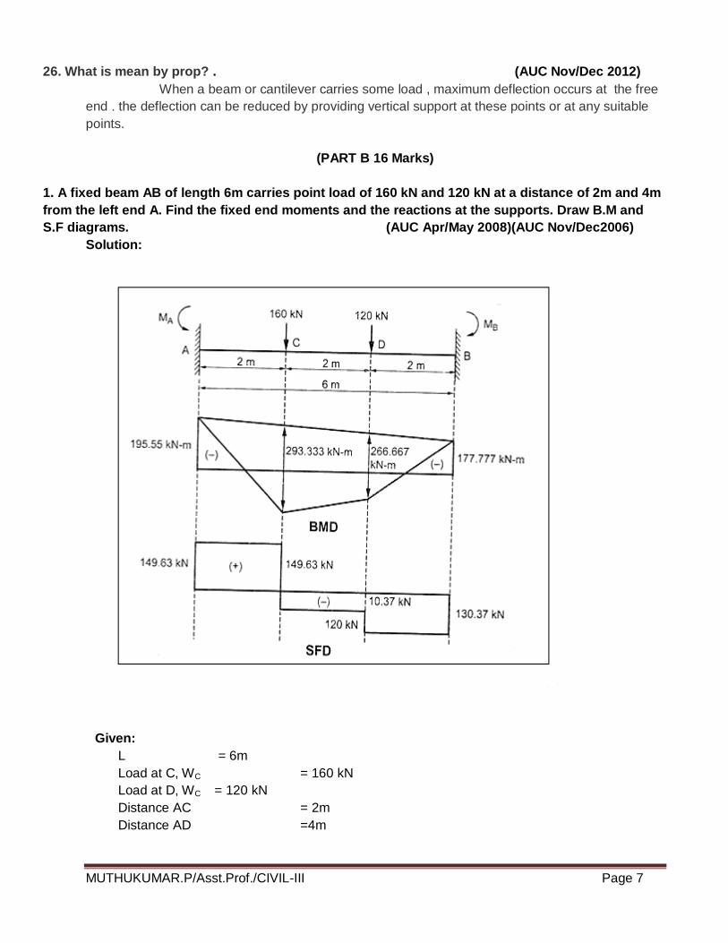
1. A fixed beam AB of length 6m carries point load of 160 kN and 120 kN at a distance of 2m and 4m
from the left end A. Find the fixed end moments and the reactions at the supports. Draw B.M and
S.F diagrams. (AUC Apr/May 2008)(AUC Nov/Dec2006)
Solution:
Given:
L = 6m
Load at C, WC = 160 kN
Load at D, WC = 120 kN
Distance AC = 2m
Distance AD =4m
MUTHUKUMAR.P/Asst.Prof./CIVIL-III Page 8
First calculate the fixed end moments due to loads at C and D separately and then
add up the moments.
Fixed End Moments:
For the load at C, a=2m and b=4m
kNmxx
M
L
abWM
A
CA
22.142)6(
)4(21602
2
1
2
2
1
kNmxx
M
L
baWM
B
CB
11.71)6(
)4(21602
2
1
2
2
1
For the load at D, a = 4m and b = 2m
kNmxx
M
L
baWM
A
DA
33.53)6(
)4(21202
2
2
2
2
2
kNmxx
M
L
baWM
B
DB
66.106)6(
)4(21602
2
2
2
2
2
Total fixing moment at A,
MA = MA1 + MA2
= 142.22 + 53.33
MA = 195.55 kNm
Total fixing moment at B,
MB =MB1 + MB2
= 71.11 + 106.66
= 177.77 kN m
B.M diagram due to vertical loads:
Consider the beam AB as simply supported. Let RA* and RB
* are the reactions at A
and B due to simply supported beam. Taking moments about A, we get
kNR
xxxR
B
B
33.1336
800
412021606
*
*
RA* = Total load - RB
*=(160 +120) – 133.33 = 146.67 kN
B.M at A = 0
B.M at C = RA* x 2 = 146.67 x 2 = 293.34 kN m
MUTHUKUMAR.P/Asst.Prof./CIVIL-III Page 9
B.M at D = 133.33 x 2 = 266.66 kN m
B.M at B= 0
S.F Diagram:
Let RA = Resultant reaction at A due to fixed end moments and vertical loads
RB = Resultant reaction at B
Equating the clockwise moments and anti-clockwise moments about A,
RB x 6 + MA = 160 x 2 + 120 x 4 + MB
RB= 130.37 kN
RA = total load – RB = 149.63 kN
S.F at A = RA = 149.63 kN
S.F at C = 149.63- 160 = -10.37 kN
S.F at D = -10.37 – 120 = -130.37 kN
S.F at B= 130.37 KN
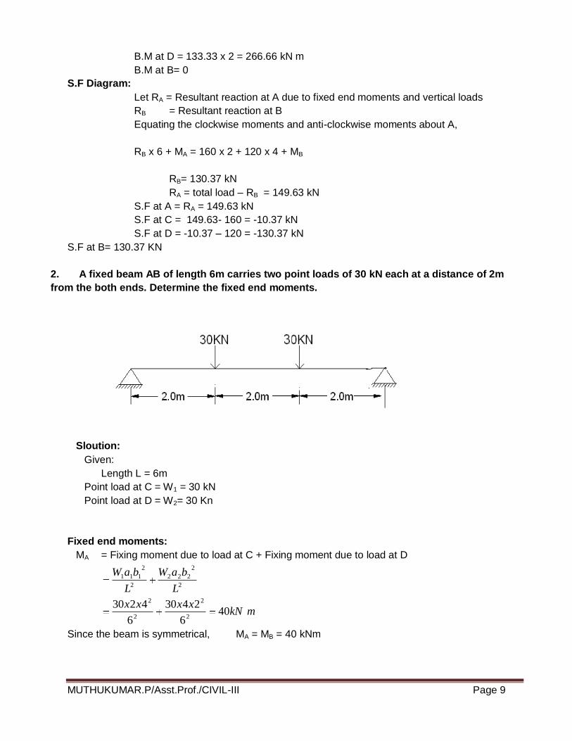
2. A fixed beam AB of length 6m carries two point loads of 30 kN each at a distance of 2m
from the both ends. Determine the fixed end moments.
Sloution:
Given:
Length L = 6m
Point load at C = W1 = 30 kN
Point load at D = W2= 30 Kn
Fixed end moments:
MA = Fixing moment due to load at C + Fixing moment due to load at D
mkNxxxx
L
baW
L
baW
406
2430
6
42302
2
2
2
2
2
222
2
2
111
Since the beam is symmetrical, MA = MB = 40 kNm
MUTHUKUMAR.P/Asst.Prof./CIVIL-III Page 10
B.M Diagram:
To draw the B.M diagram due to vertical loads, consider the beam AB as simply supported. The
reactions at A and B is equal to 30kN.
B.M at A and B = 0
B.M at C =30 x 2 = 60 kNm
B.M at D = 30 x 2 = 60 kNm
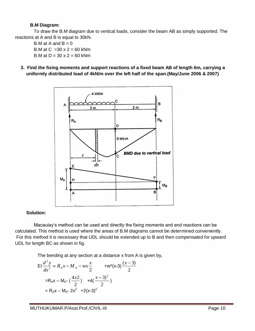
3. Find the fixing moments and support reactions of a fixed beam AB of length 6m, carrying a
uniformly distributed load of 4kN/m over the left half of the span.(May/June 2006 & 2007)
Solution:
Macaulay’s method can be used and directly the fixing moments and end reactions can be
calculated. This method is used where the areas of B.M diagrams cannot be determined conveniently.
For this method it is necessary that UDL should be extended up to B and then compensated for upward
UDL for length BC as shown in fig.
The bending at any section at a distance x from A is given by,
EI22
2 xwxMxR
dx
ydAA +w*(x-3)
2
)3(x
=RAx – MA- (2
24x) +4(
2
)3 2x)
= RAx – MA- 2x2 +2(x-3)2
MUTHUKUMAR.P/Asst.Prof./CIVIL-III Page 11
Integrating, we get
EIdx
dy=RA
2
2x-MAx - 2
3
3x+C1 +
3
)3(2 3x ------- (1)
When x=0, dx
dy=0.
Substituting this value in the above equation up to dotted line,
C1 = 0
Therefore equation (1) becomes
EIdx
dy=RA
2
2x-MAx - 2
3
3x +
3
)3(2 3x
Integrating we get
12
)3(2
12
2
26
4
2
423 xC
xxMxRyEI A
A
When x = 0 , y = 0
By substituting these boundary conditions upto the dotted line,
C2 = 0
6
)3(1
626
4423xxxMxR
yEI AA ________(ii)
By subs x =6 & y = 0 in equation (ii)
6
)36(1
6
6
2
6
6
60
4423
AA MR
5.132161836 AA MR
18RA – 9 MA = 101.25 ------------- (iii)
At x =6, 0dx
dy in equation (i)
332
363
26
3
26
2
60 xxMxR AA
126618
018144618
AA
AA
MR
xMR
By solving (iii) & (iv)
MA = 8.25 kNm
By substituting MA in (iv)
126 = 18 RA – 6 (8.25)
RA = 9.75 kN
RB = Total load – RA
RB = 2.25 kN
MUTHUKUMAR.P/Asst.Prof./CIVIL-III Page 12
By equating the clockwise moments and anticlockwise moments about B
MB + RA x 6 = MA + 4x3 (4.5)
MB = 3.75 kNm
Result:
MA = 8.25 kNm
MB = 3.75 kNm
RA = 9.75 kN
RB = 2.25 KN
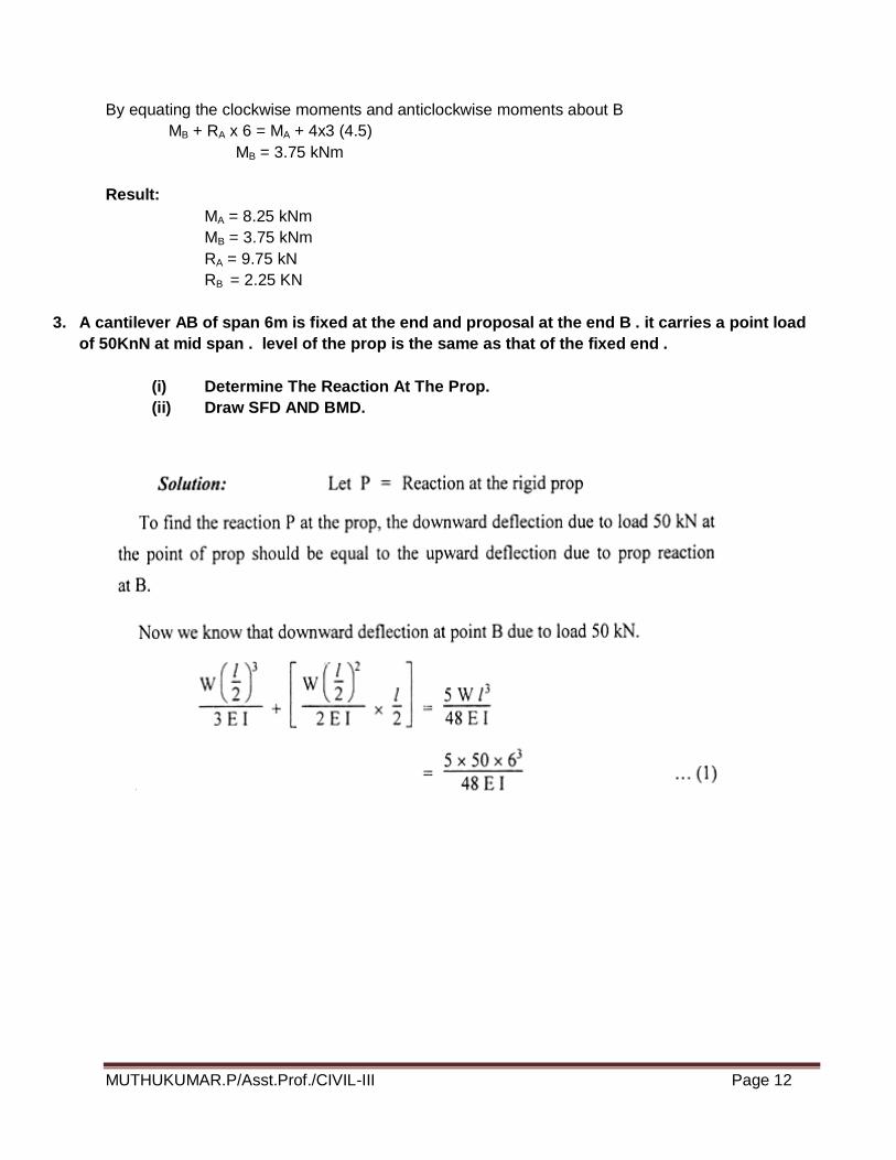
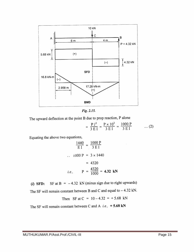
3. A cantilever AB of span 6m is fixed at the end and proposal at the end B . it carries a point load
of 50KnN at mid span . level of the prop is the same as that of the fixed end .
(i) Determine The Reaction At The Prop.
(ii) Draw SFD AND BMD.

MUTHUKUMAR.P/Asst.Prof./CIVIL-III Page 13

MUTHUKUMAR.P/Asst.Prof./CIVIL-III Page 14
4. Analysis the propped cantilever beam of the length 10m is subjected to point load of 10KN
acting at a 6m from fixed and draw SFD and BMD. (AUC Nov/Dec 2010 )
MUTHUKUMAR.P/Asst.Prof./CIVIL-III Page 15
MUTHUKUMAR.P/Asst.Prof./CIVIL-III Page 16
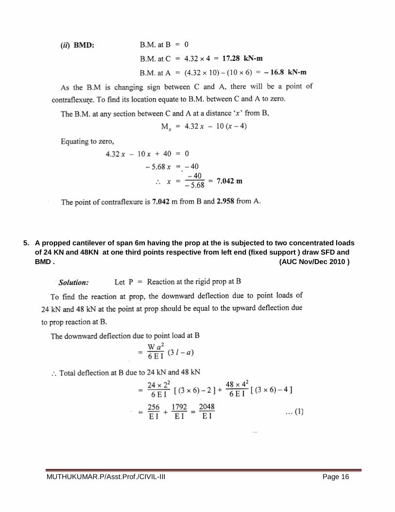
5. A propped cantilever of span 6m having the prop at the is subjected to two concentrated loads
of 24 KN and 48KN at one third points respective from left end (fixed support ) draw SFD and
BMD . (AUC Nov/Dec 2010 )
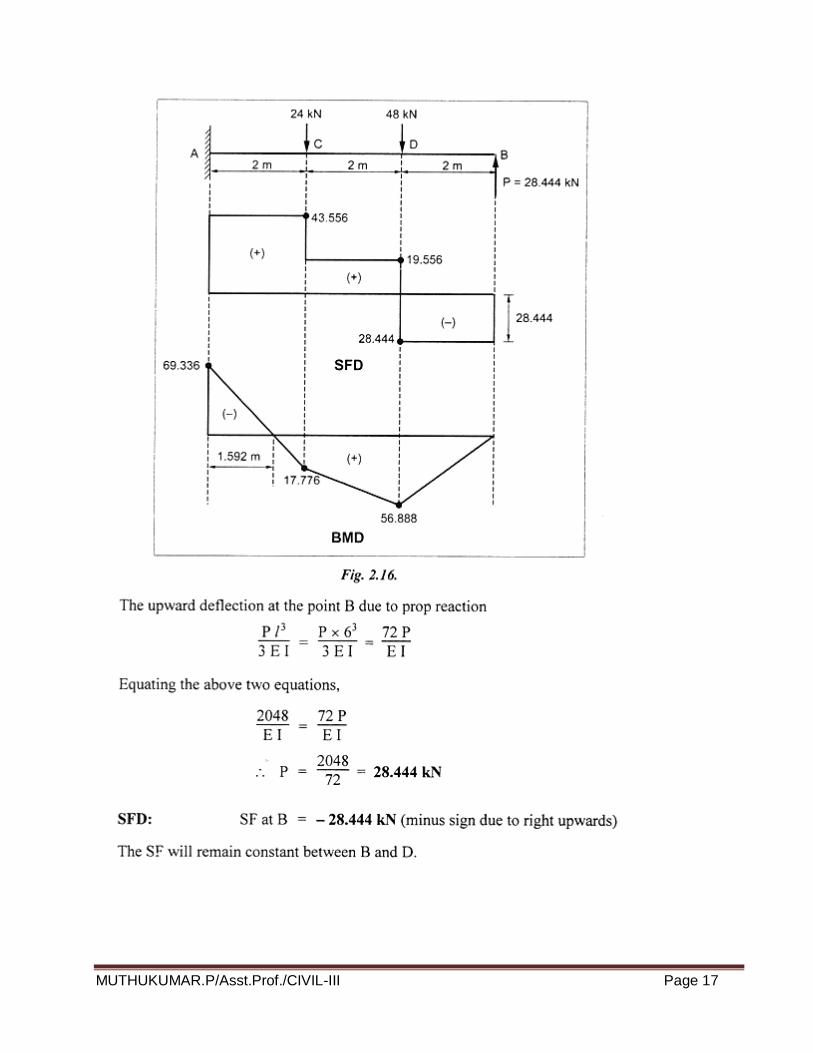
MUTHUKUMAR.P/Asst.Prof./CIVIL-III Page 17

MUTHUKUMAR.P/Asst.Prof./CIVIL-III Page 18
MUTHUKUMAR.P/Asst.Prof./CIVIL-III Page 19
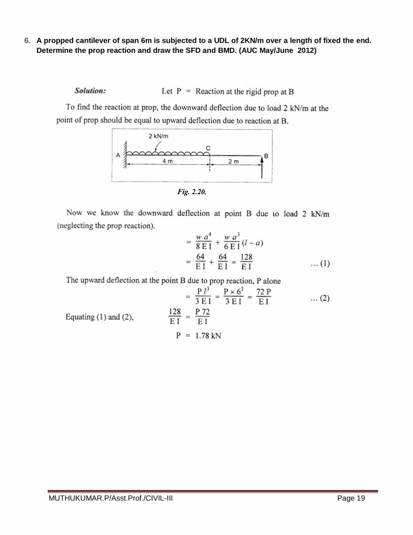
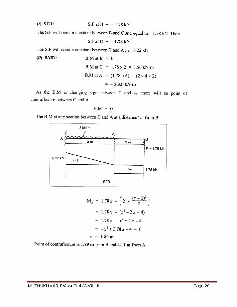
6. A propped cantilever of span 6m is subjected to a UDL of 2KN/m over a length of fixed the end.
Determine the prop reaction and draw the SFD and BMD. (AUC May/June 2012)
MUTHUKUMAR.P/Asst.Prof./CIVIL-III Page 20
MUTHUKUMAR.P/Asst.Prof./CIVIL-III Page 21
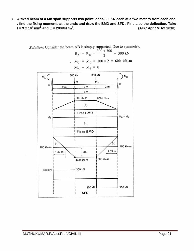
7. A fixed beam of a 6m span supports two point loads 300KN each at a two meters from each end
. find the fixing moments at the ends and draw the BMD and SFD . Find also the deflection. Take
I = 9 x 108 mm2 and E = 200KN /m2. (AUC Apr / M AY 2010)
MUTHUKUMAR.P/Asst.Prof./CIVIL-III Page 22

MUTHUKUMAR.P/Asst.Prof./CIVIL-III Page 23
8. For The fixed beam shown in fig. Draw the BMD and SFD.
MUTHUKUMAR.P/Asst.Prof./CIVIL-III Page 24
MUTHUKUMAR.P/Asst.Prof./CIVIL-III Page 25
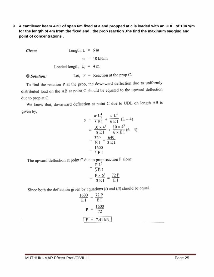
9. A cantilever beam ABC of span 6m fixed at a and propped at c is loaded with an UDL of 10KN/m
for the length of 4m from the fixed end . the prop reaction .the find the maximum sagging and
point of concentrations .
MUTHUKUMAR.P/Asst.Prof./CIVIL-III Page 26
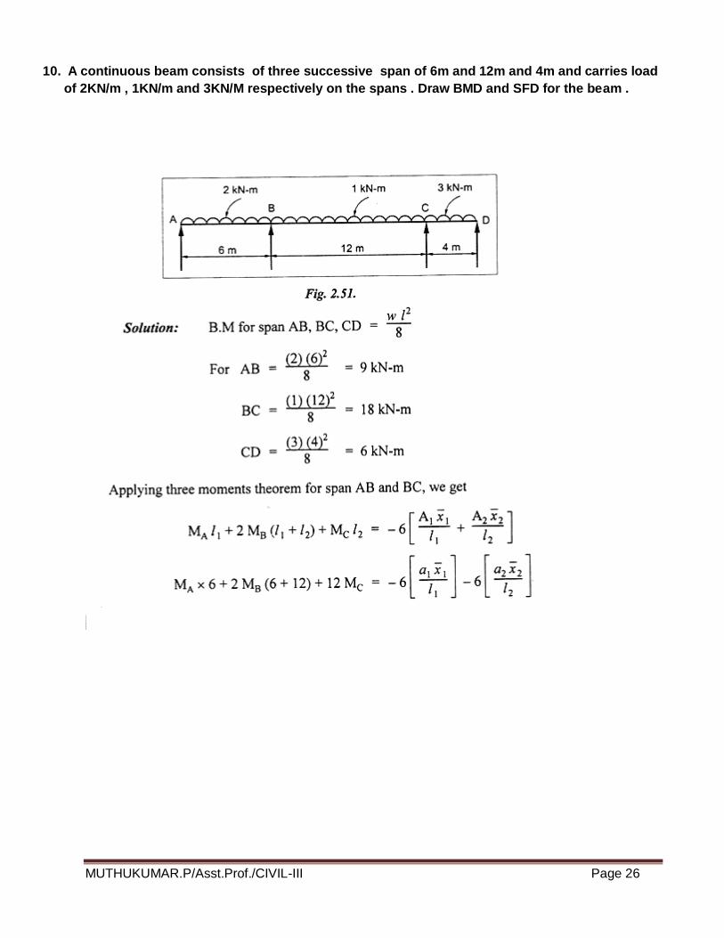
10. A continuous beam consists of three successive span of 6m and 12m and 4m and carries load
of 2KN/m , 1KN/m and 3KN/M respectively on the spans . Draw BMD and SFD for the beam .

MUTHUKUMAR.P/Asst.Prof./CIVIL-III Page 27
MUTHUKUMAR.P/Asst.Prof./CIVIL-III Page 28
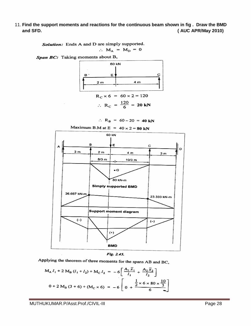
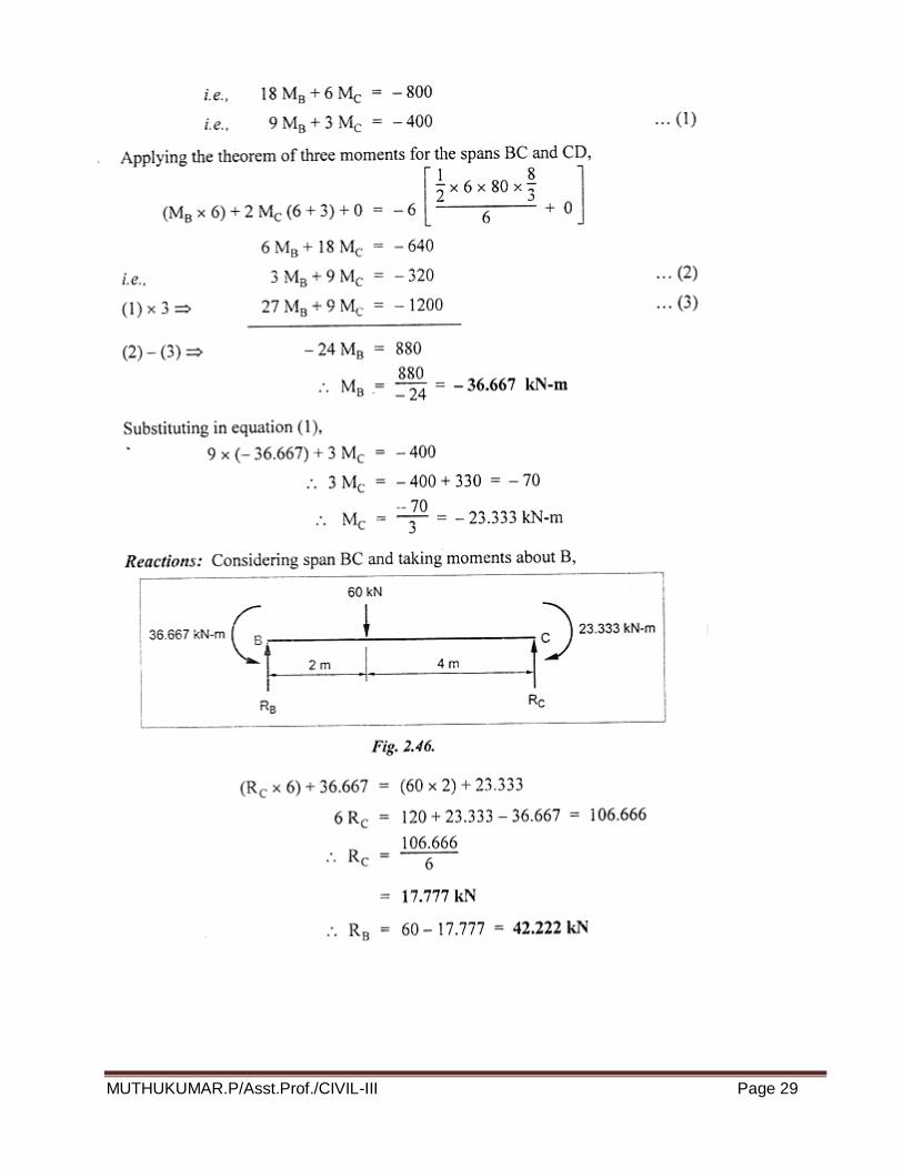
11. Find the support moments and reactions for the continuous beam shown in fig . Draw the BMD
and SFD. ( AUC APR/May 2010)
MUTHUKUMAR.P/Asst.Prof./CIVIL-III Page 29
MUTHUKUMAR.P/Asst.Prof./CIVIL-III Page 30
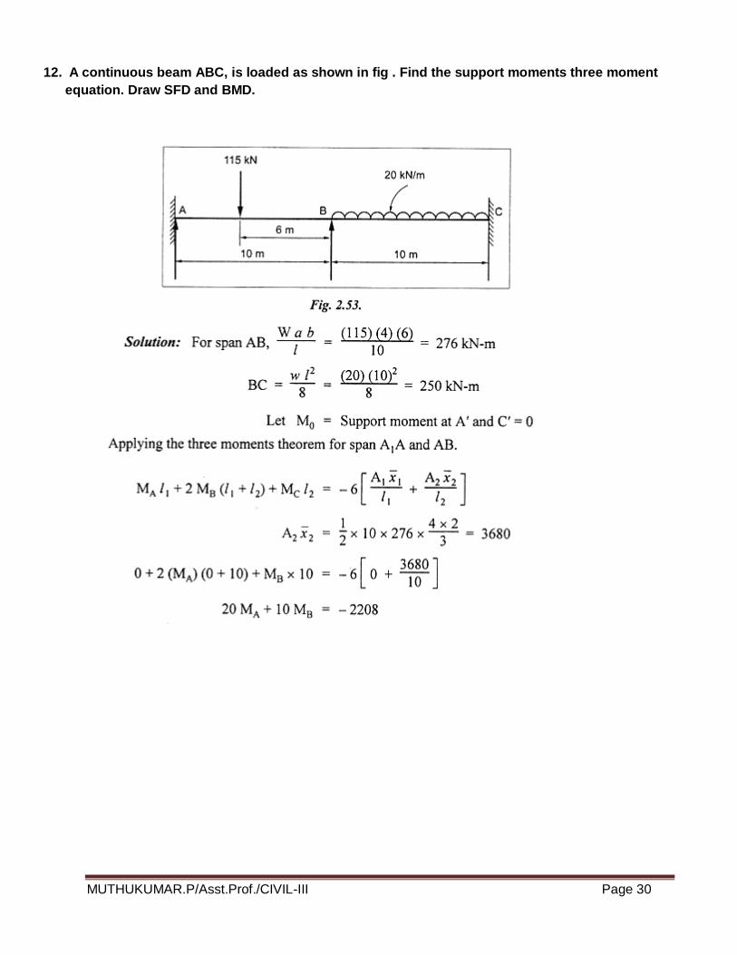
12. A continuous beam ABC, is loaded as shown in fig . Find the support moments three moment
equation. Draw SFD and BMD.

MUTHUKUMAR.P/Asst.Prof./CIVIL-III Page 31
MUTHUKUMAR.P/Asst.Prof./CIVIL-III Page 32
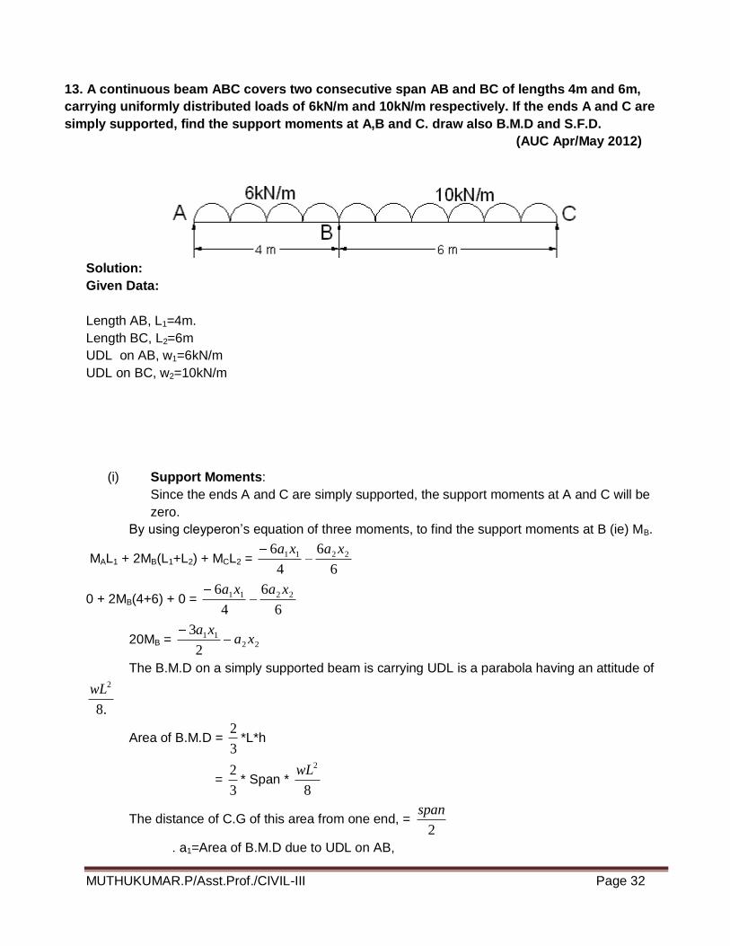
13. A continuous beam ABC covers two consecutive span AB and BC of lengths 4m and 6m,
carrying uniformly distributed loads of 6kN/m and 10kN/m respectively. If the ends A and C are
simply supported, find the support moments at A,B and C. draw also B.M.D and S.F.D.
(AUC Apr/May 2012)
Solution:
Given Data:
Length AB, L1=4m.
Length BC, L2=6m
UDL on AB, w1=6kN/m
UDL on BC, w2=10kN/m
(i) Support Moments:
Since the ends A and C are simply supported, the support moments at A and C will be
zero.
By using cleyperon’s equation of three moments, to find the support moments at B (ie) MB.
MAL1 + 2MB(L1+L2) + MCL2 = 6
6
4
6 2211 xaxa
0 + 2MB(4+6) + 0 = 6
6
4
6 2211 xaxa
20MB = 2211
2
3xa
xa
The B.M.D on a simply supported beam is carrying UDL is a parabola having an attitude of
.8
2wL
Area of B.M.D = 3
2*L*h
= 3
2* Span *
8
2wL
The distance of C.G of this area from one end, = 2
span
. a1=Area of B.M.D due to UDL on AB,
MUTHUKUMAR.P/Asst.Prof./CIVIL-III Page 33
= 3
2*4*
8
)4(6 2
=32
x1=2
1L
= 4/2
= 2 m.
a2= Area of B.M.D due to UDL on BC,
= 3
2*6*
8
)6(10 2
= 180m.
x2=L2 / 2
= 6 / 2
=3m
Substitute these values in equation(i).
We get,
20MB = )3*180(2
2*32*3
= 96+540
MB =31.8 kNm.
(ii) B.M.D
The B.M.D due to vertical loads (UDL) on span AB and span BC.
Span AB:
=8
2
11Lw
=8
4*6 2
=12kNm
Span BC: =8
2
22 Lw
=8
6*10 2
=45kNm
(iii) S.F.D:
To calculate Reactions,
For span AB, taking moments about B, we get
(RA*4)-(6*4*2) – MB=0
4RA – 48 = 31.8 (MB=31.8, -ve sign is due to hogging moment.
RA=4.05kN
Similarly,
For span BC, taking moment about B,

MUTHUKUMAR.P/Asst.Prof./CIVIL-III Page 34
(Rc*6)-(6*10*3) – MB=0
6RC – 180=-31.8
RC=24.7kN.
RB=Total load on ABC –(RA+RB)
=(6*4*(10*6))-(4.05+24.7)
=55.25kN.
RESULT:
MA=MC=0
MB=31.8kNm
RA=4.05kN
RB=55.25kN
RC=24.7kN
14. A continuous beam ABCD of length 15m rests on four supports covering 3 equal spans and
carries a uniformly distributed load of 1.5 kN/m length .Calculate the moments and reactions at the
supports. Draw The S.F.D and B.M.D.
Solution:
Given:
Length AB = L1 = 5m
Length BC = L2 = 5m
Length CD = L3 = 5m
u.d.l w1 = w2 = w3 = 1.5 kN/m
Since the ends A and D are simply supported, the support moments at A and D will be Zero.
MA=0 and MD=0
For symmetry MB=0
(i)To calculate support moments:
MUTHUKUMAR.P/Asst.Prof./CIVIL-III Page 35
To find the support moments at B and C, by using claperon’s equations of three moments for ABC
and BCD.
For ABC,
MAL1+[2MB(L1+L2)]+MCL2=2
22
1
11 66
L
xa
L
xa
0+[2MB(5+5)]+[MC(5)]= 5
6
5
6 2211 xaxa
20MB+5MC= )(5
62211 xaxa --------------------------------------(i)
a1=Area of BMD due to UDL on AB when AB is considered as simply supported beam.
= **3
2AB Altitude of parabola (Altitude of parabola=
8
11Lw)
= 8
)5(*5.1*5*
3
2 2
=15.625
x1=L1/2
=5/2=2.5m
Due to symmetry
.a2=a1=15.625
x2=x1=2.5
subs these values in eqn(i)
20MB+5MC = )]5.2*625.15()5.2*625.15[(5
6
=93.75
Due to symmetry MB=MC
20MB+5MB=93.75
MB=3.75kNm.
MB=MC=3.75kNm.
(ii) To calculate BM due to vertical loads:
The BMD due to vertical loads(here UDL) on span AB, BC and CD (considering each span as
simply supported ) are shown by parabolas of altitude
kNmLw
6875.48
5.1*5.1
8
22
11 each.
(iii)To calculate support Reactions:
Let RA,RB,RC and RD are the support reactions at A,B,C and D.
Due to symmetry
RA=RD
RB=RC
For span AB, Taking moments about B,
We get

MUTHUKUMAR.P/Asst.Prof./CIVIL-III Page 36
MB=(RA*5)-(1.5*5*2.5)
-3.75=(RA*5)-18.75
RA=3.0kN.
Due to symmetry
RA=RD=3.0kN
RB=RC
RA+RB+RC+RD=Total load on ABCD
3+RB+RB+3=1.5*15
RB=8.25kN
RC=8.25kN.
Result:
MA = MD = 0
MB=MC=3.75kNm.
RA=RD=3.0kN
RB=8.25kN
RC=8.25kN.
15. A continuous beam ABCD, simply supported at A,B, C and D is loaded as shown in fig.
Find the moments over the beam and draw B.M.D and S.F.D. (Nov/ Dec 2003)
Solution:
Given:
Length AB = L1 = 6m
Length BC = L2 = 5m
Length CD = L3 = 4m
Point load W1 = 9kN
Point load W2 = 8kN
u.d.l on CD, w = 3 kN/m

MUTHUKUMAR.P/Asst.Prof./CIVIL-III Page 37
(i) B.M.D due to vertical loads taking each span as simply supported:
Consider beam AB, B.M at point load at E = kNmL
abW12
6
4*2*9
1
1
Similarly B.M at F = kNmL
abW6.9
6
3*2*82
2
B.M at the centre of a simply supported beam CD, carrying U.D.L
kNmwL
68
4*3
8
22
3
(ii) B.M.D due to support moments:
Since the beam is simply supported MA =MD = 0
By using Clapeyron’s Equation of Three Moments:
a) For spans AB and BC
MAL1 + 2MB(L1+L2) + MCL2 = 6
6
4
6 2211 xaxa
5
6
6
6)5()56(20 2211 xaxa
MM cB
22115
6522 xaxaMM CB ------------ (i)
a1x1 = ½*6*12*L+a/3 = ½*6*12*(6+2)/3 = 96
a2x2 = ½*5*9.6*L+b/3 = ½*5*9.6*(6+4)/3 = 64
Substitute the values in equation (i)
22MB + 5MC = 96+6/5*64
22MB + 5MC = 172.8 ------------ (ii)
b) For spans BC and CD
MBL2 + 2MC(L2+L3) + MDL3 = 3
33
2
22 66
L
xa
L
xa
MB*5 + 2MC(5+4) +0 = 4
6
5
6 3322 xaxa
4
6
5
6185 332 xaax
MM CB ----------- (iii)
a2x2 = ½ * 5 * 9.6 *(L+a)/3 =1/2 * 5 * 9.6 *(5+2)/3 = 56
a3x3 = 2/3 * 4*6*4/2 =32
Substitute these values in equation (iii)
MUTHUKUMAR.P/Asst.Prof./CIVIL-III Page 38
4
32*6
5
56*6185 CB MM
2.115185 CB MM
By solving equations (ii) &(iv)
MB = 6.84 kNm and MC = 4.48 kNm
(iii) Support Reactions:
For the span AB, Taking moment about B,
MB = RA * 6 – 9*4
= 366 AR
RA = KN86.46
84.636
For the span CD, taking moments about C
)48.4(2
4434 CDC MRM
RD = 4.88KN
For ABC taking moment about C
Mc = 3*85*45956* BA RR
11*86.424815 BR
RB = 9.41 kN
RC = Total load on ABCD – (RA +RB+RD)
RC = (9+8+4*3) – (4.86+9.41+4.88)
RC = 9.85 kN
Result:
MA = MD = 0
MB = 6.84 kNm and MC = 4.48 kNm
RA = 4.86kN
RB = 9.41kN
RC = 9.85 kN
RD = 4.88KN

MUTHUKUMAR.P/Asst.Prof./CIVIL-III Page 39
16. Using the theorem of three moments draw the shear force and bending moment
diagrams for the following continuous beam. (April / May 2003)
Solution:
Given:
Length AB, L1=4m.
Length BC, L2=3m.
Length CD, L3=4m.
UDL on AB, w=4 kN/m
Point load in BC, W1=4kN/m
Point load in CD, W1=6kN
(i) Bending Moment to Vertical Loads:
Consider beam AB, B.M=8
4*4
8
22wL
=8kNm.
Similarly for beam BC,
B.M=3
1*2*6
2
1
L
abW
=4kNm
Similarly for beam CD,
B.M=4
3*1*8
3
2
L
abW
=6kNm
(ii) Bending Moment to support moments:
Let MA,MB,MC And MD be the support moments at A,B,C and D. Since the ends is simply
supported, MA =MD=0.
By using Clayperon’s equation of three moments for span AB and BC,
MAL1+[2MB(L1+L2) ]+ MCL2 =2
22
1
11 66
L
xa
L
xa
MUTHUKUMAR.P/Asst.Prof./CIVIL-III Page 40
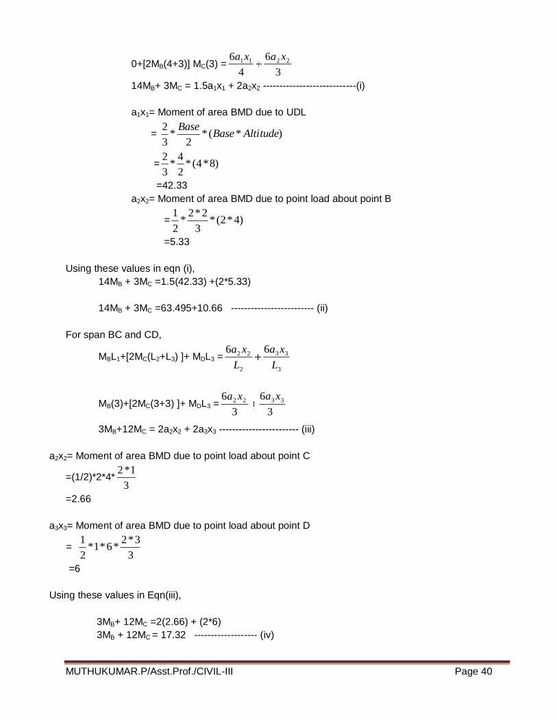
0+[2MB(4+3)] MC(3) =3
6
4
6 2211 xaxa
14MB+ 3MC = 1.5a1x1 + 2a2x2 ----------------------------(i)
a1x1= Moment of area BMD due to UDL
= )*(*2
*3
2AltitudeBase
Base
= )8*4(*2
4*
3
2
=42.33
a2x2= Moment of area BMD due to point load about point B
= )4*2(*3
2*2*
2
1
=5.33
Using these values in eqn (i),
14MB + 3MC =1.5(42.33) +(2*5.33)
14MB + 3MC =63.495+10.66 ------------------------- (ii)
For span BC and CD,
MBL1+[2MC(L2+L3) ]+ MDL3 =3
33
2
22 66
L
xa
L
xa
MB(3)+[2MC(3+3) ]+ MDL3 =3
6
3
6 3322 xaxa
3MB+12MC = 2a2x2 + 2a3x3 ------------------------ (iii)
a2x2= Moment of area BMD due to point load about point C
=(1/2)*2*4*3
1*2
=2.66
a3x3= Moment of area BMD due to point load about point D
= 3
3*2*6*1*
2
1
=6
Using these values in Eqn(iii),
3MB+ 12MC =2(2.66) + (2*6)
3MB + 12MC = 17.32 ------------------- (iv)
MUTHUKUMAR.P/Asst.Prof./CIVIL-III Page 41
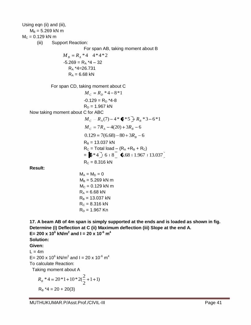
Using eqn (ii) and (iii),
MB = 5.269 kN m
MC = 0.129 kN m
(iii) Support Reaction:
For span AB, taking moment about B
2*4*44*AB RM
-5.269 = RA *4 – 32
RA *4=26.731
RA = 6.68 kN
For span CD, taking moment about C
1*84*DC RM
-0.129 = RD *4-8
RD = 1.967 kN
Now taking moment about C for ABC
1*63*5*4*4)7( BAC RRM
63)20(47 BAC RRM
6380)68.6(7129.0 BR
RB = 13.037 kN
RC = Total load – (RA +RB + RC)
= 037.13967.168.6864*4
RC = 8.316 kN
Result:
MA = MD = 0
MB = 5.269 kN m
MC = 0.129 kN m
RA = 6.68 kN
RB = 13.037 kN
RC = 8.316 kN
RD = 1.967 Kn
17. A beam AB of 4m span is simply supported at the ends and is loaded as shown in fig.
Determine (i) Deflection at C (ii) Maximum deflection (iii) Slope at the end A.
E= 200 x 106 kN/m2 and I = 20 x 10-6 m4
Solution:
Given:
L = 4m
E= 200 x 106 kN/m2 and I = 20 x 10-6 m4
To calculate Reaction:
Taking moment about A
)112
2(2*101*204*BR
RB *4 = 20 + 20(3)
MUTHUKUMAR.P/Asst.Prof./CIVIL-III Page 42
RB = 80/4 = 20 kN
RA = Total load - RB
= (10*2+20) -20
RA = 20 kN
By using Macaulay’s method:
2
)2(10)1(2020
2
2
2 xxx
xd
ydEIM X
Integrating we get
3
)2(5)1(1010
32
1
2 xxCx
dx
dyEI
Integrating we get
12
)2(5
3
)1(10
3
10 43
21
3 xxCxC
xEIy ---------- (ii)
When x = 0, y = 0 in equation (ii) we get C2 = 0
When x = 4m, y = 0 in equation (ii)
43
1
3 2412
5)14(
3
104)4(
3
100 C
= 213.33 +4C1 – 90 -6.67
C1 = -29.16
Hence the slope and deflection equations are
Slope Equation:
3
)2(5)1(1016.2910
322 x
xxdx
dyEI
Deflection Equation:
12
)2(5
3
)1(1016.29
3
10 433 xxx
xEIy
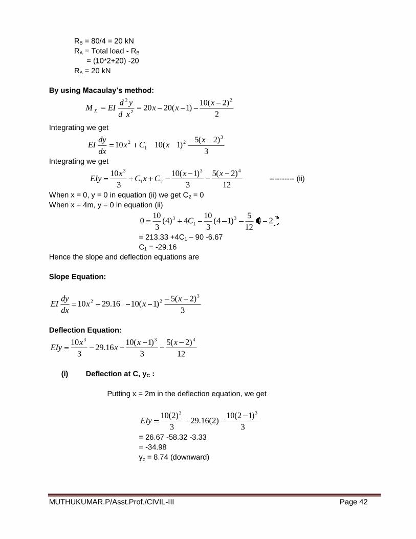
(i) Deflection at C, yC :
Putting x = 2m in the deflection equation, we get
3
)12(10)2(16.29
3
)2(10 33
EIy
= 26.67 -58.32 -3.33
= -34.98
yc = 8.74 (downward)
MUTHUKUMAR.P/Asst.Prof./CIVIL-III Page 43
(ii) Maximum Deflection , ymax :
The maximum deflection will be very near to mid-point C. Let us assume
that it occurs in the sections between D and C. For maximum deflection equating the slope at
the section to zero, we get
22 )1(1016.2910 xx
dx
dyEI
10x2 -29.16 -10(x-1)2 = 0
10x2 -29.16 -10 (x2 -2x+1) = 0
x = 39.16/20 =1.958 m
3
)1958.1(10)958.1(16.29
3
)958.1(10 33
EIy
ymax = -35/EI
ymax = 8.75 mm (downward)
(iii) Slope at the end A, θA:
Putting x = 0 in the slope equation,
16.29dx
dyEI
θA = dy/dx = -29.16/EI
θA = -0.00729 radians
θA = -0.417º
Result:
(i) Deflection at C = 8.74 mm
(ii) Maximum deflection = 8.75 mm
(iii) Slope at the end A, θA = -0.417º
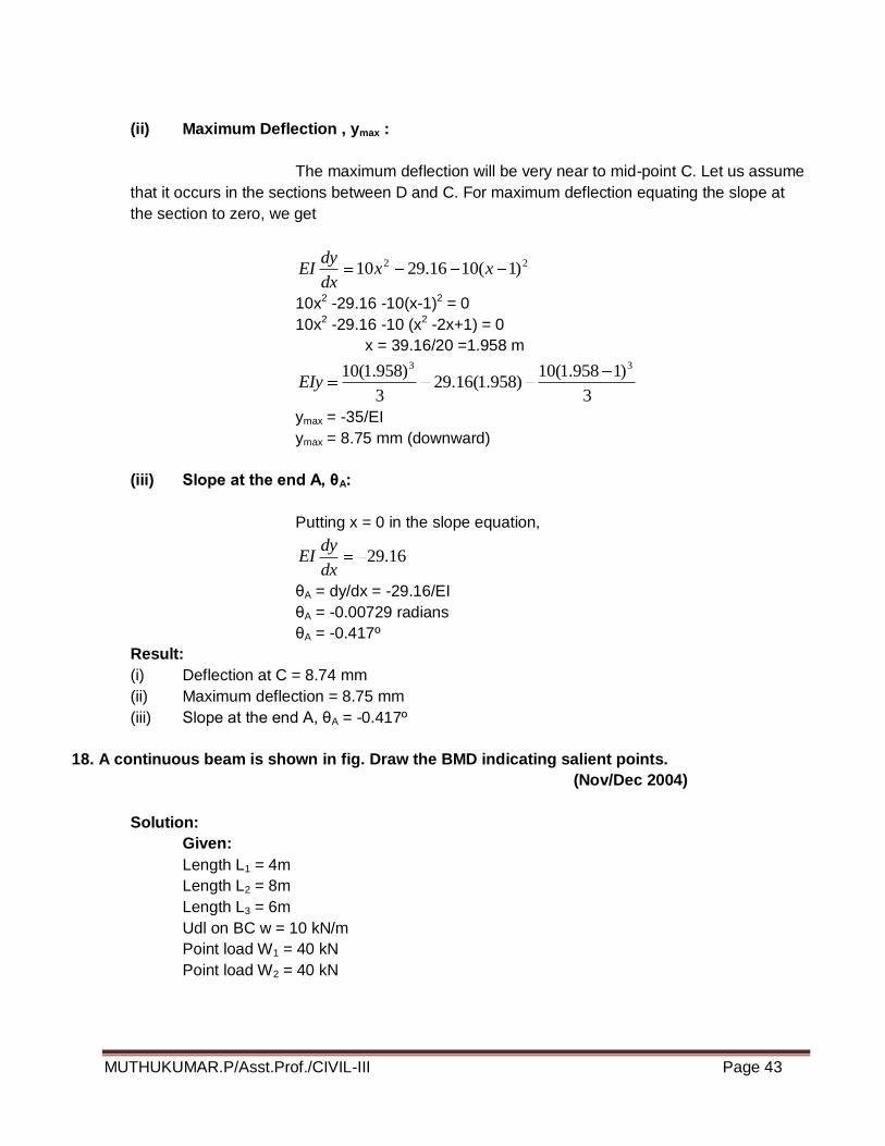
18. A continuous beam is shown in fig. Draw the BMD indicating salient points.
(Nov/Dec 2004)
Solution:
Given:
Length L1 = 4m
Length L2 = 8m
Length L3 = 6m
Udl on BC w = 10 kN/m
Point load W1 = 40 kN
Point load W2 = 40 kN
MUTHUKUMAR.P/Asst.Prof./CIVIL-III Page 44
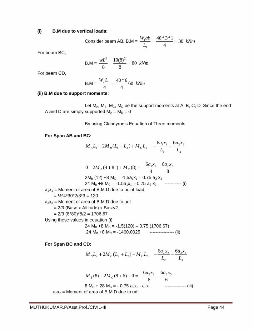
(i) B.M due to vertical loads:
Consider beam AB, B.M = kNmL
abW30
4
1*3*40
1
1
For beam BC,
B.M = kNmwL
808
)8(10
8
22
For beam CD,
B.M = kNmLW
604
6*40
4
32
(ii) B.M due to support moments:
Let MA, MB, MC, MD be the support moments at A, B, C, D. Since the end
A and D are simply supported MA = MD = 0
By using Clapeyron’s Equation of Three moments.
For Span AB and BC:
2
22
1
112211
66)(2
L
xa
L
xaLMLLMLM CBA
8
6
4
6)8()84(20 2211 xaxa
MM CB
2MB (12) +8 MC = -1.5a1x1 – 0.75 a2 x2
24 MB +8 MC = -1.5a1x1 – 0.75 a2 x2 ----------- (i)
a1x1 = Moment of area of B.M.D due to point load
= ½*4*30*2/3*3 = 120
a2x2 = Moment of area of B.M.D due to udl
= 2/3 (Base x Altitude) x Base/2
= 2/3 (8*80)*8/2 = 1706.67
Using these values in equation (i)
24 MB +8 MC = -1.5(120) – 0.75 (1706.67)
24 MB +8 MC = -1460.0025 ---------------- (ii)
For Span BC and CD:
3
33
2
223322
66)(2
L
xa
L
xaLMLLMLM DCB
6
6
8
60)68(2)8( 3322 xaxa
MM CB
8 MB + 28 MC = - 0.75 a2x2 - a3x3 -------------- (iii)
a2x2 = Moment of area of B.M.D due to udl

MUTHUKUMAR.P/Asst.Prof./CIVIL-III Page 45
= 2/3 (Base x Altitude) x Base/2
= 2/3 (8*80)*8/2 = 1706.67
a3 x3 = Moment of area of B.M.D due to point load
= ½ * b*h*L/3
= ½ * 6*60*6/3
= 360
Using these values in equation (iii)
8 MB + 28 MC = - 0.75 (1706.67) – 360
8 MB + 28 MC = - 1640.0025 ------------------ (iv)
From (ii) & (iv)
MC = 45.526 kNm
MB = 45.657 kNm
Result:
MA = MD = 0
MC = 45.526 kNm
MB = 45.657 kNm
19. For the fixed beam shown in fig. draw BMD and SFD. (AUC Nov / Dec 2004)
Solution:
(i) B.M.D due to vertical loads taking each span as simply supported:
Consider beam AB as simply supported. The B.M at the centre of AB
kNmwL
25.28
)3(*2
8
22
1
(ii) B.M.D due to support moments:
As beam is fixed at A and B, therefore introduce an imaginary zero span AA1 and BB1 to the left of
A and to the right of B. The support moments at A1 and B1 are zero.
Let M0 = Support moment at A1 and B1 and it is zero.
MA = Fixing moment at A
MB = Fixing moment at B
MC = Support moment at C
To find MA, MB and MC, Theorem of three moments is used.
(a) For the span A1A and AC,
1
11
0
00110
66)0(20*
L
xa
L
xaLMLMM CA
1
116)3()3(2
L
xaMM CA
MUTHUKUMAR.P/Asst.Prof./CIVIL-III Page 46
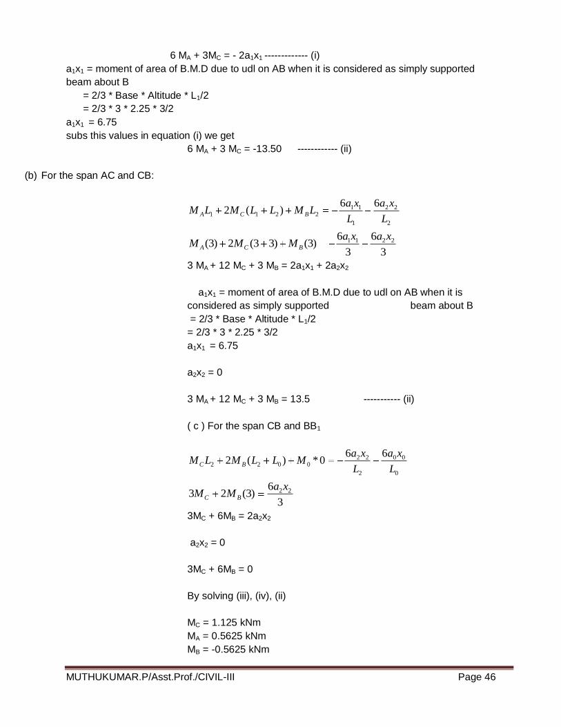
6 MA + 3MC = - 2a1x1 ------------- (i)
a1x1 = moment of area of B.M.D due to udl on AB when it is considered as simply supported
beam about B
= 2/3 * Base * Altitude * L1/2
= 2/3 * 3 * 2.25 * 3/2
a1x1 = 6.75
subs this values in equation (i) we get
6 MA + 3 MC = -13.50 ------------ (ii)
(b) For the span AC and CB:
2
22
1
112211
66)(2
L
xa
L
xaLMLLMLM BCA
3
6
3
6)3()33(2)3( 2211 xaxa
MMM BCA
3 MA + 12 MC + 3 MB = 2a1x1 + 2a2x2
a1x1 = moment of area of B.M.D due to udl on AB when it is
considered as simply supported beam about B
= 2/3 * Base * Altitude * L1/2
= 2/3 * 3 * 2.25 * 3/2
a1x1 = 6.75
a2x2 = 0
3 MA + 12 MC + 3 MB = 13.5 ----------- (ii)
( c ) For the span CB and BB1
0
00
2
220022
660*)(2
L
xa
L
xaMLLMLM BC
3
6)3(23 22xa
MM BC
3MC + 6MB = 2a2x2
a2x2 = 0
3MC + 6MB = 0
By solving (iii), (iv), (ii)
MC = 1.125 kNm
MA = 0.5625 kNm
MB = -0.5625 kNm
MUTHUKUMAR.P/Asst.Prof./CIVIL-III Page 47
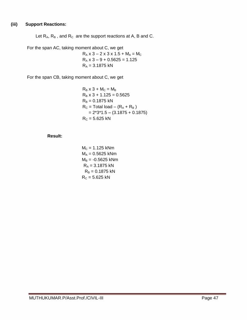
(iii) Support Reactions:
Let RA, RB , and RC are the support reactions at A, B and C.
For the span AC, taking moment about C, we get
RA x 3 – 2 x 3 x 1.5 + MA = MC
RA x 3 – 9 + 0.5625 = 1.125
RA = 3.1875 kN
For the span CB, taking moment about C, we get
RB x 3 + MC = MB
RB x 3 + 1.125 = 0.5625
RB = 0.1875 kN
RC = Total load – (RA + RB )
= 2*3*1.5 – (3.1875 + 0.1875)
RC = 5.625 kN
Result:
MC = 1.125 kNm
MA = 0.5625 kNm
MB = -0.5625 kNm
RA = 3.1875 kN
RB = 0.1875 kN
RC = 5.625 kN