easep/psep solar panel development design of the ease … · each cell in the module is ... solar...
TRANSCRIPT

-~
NO. REV. NO.
EATM-15
PAGE OF
~ Systems Division DATE
EASEP /PSEP Solar Panel Development Design of the EASE-PSEP Sola!" Panel Array
20 November 1968
--~· #/ .
..£./ ,:..<; // Prepared by: __ rl____:.\ _' '-::-:-'-' ';;_ ..... _£_.>_· :;;,_"'-_Jrt ___ _
R. Gibson
Approved by:. __ k:....:!!!!!!_...""' ... -.... ··_· ~k+"'--.:L'_;;;J....;::::::..··-=·~::!!:!!!e::...._ K. Hsi
NO. REV. NO.
EATM-15 EASEP /PSEP Solar Panel Development
~ Systems Division
Design of the EASE-PSEP Solar Panel Array~PA::G:,:E:..::=l=~o:F~=2=7=
DATE 20 Nov. 1968
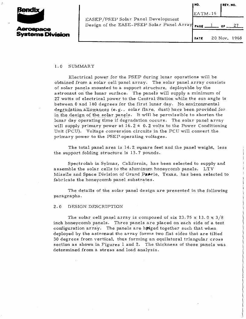
1. 0 SUMMARY
Electrical power for the PSEP during lunar operations will be obtained from a solar cell panel array. The sol~r panel array consists of solar panels mounted to a support structure, deployable by the astronaut on the lunar su:dace. The panels will supply a minimum of 27 watts of electrical power to the Central "Station while the sun angle is between 0 and 180 degrees for the first lunar day. No envi:r:onmental d~g.!~9-_<!g,tionallc)'W,?o:tl9~§ (e. g., solar flare, dust) have been provided for intl'le. ciesign of thesolar panels. It will be permissible to shorten the lunar day operating time if degradation occurs. The solar panel array will supply primary power at 16.2 ± 0. 2 vo~ts to the Power Conditioning Unit (PCU). Voltage conversion circuits in the PCU will convert the primary power to the PSEP operating voltages.
The total panel area is 14. 2 square feet and the panel weight, less the support folding structure is 13.7 pounds.
Spectrolab in Sylmar, California, has been selected to supply and assemble the solar cells to the aluminum honeycomb panels. LTV Missile and Space Division of Grand PJt~rie, Texas, has been selected to fabricate the honeycomb panel substr~tes.
The details of the solar panel design are presented in the following paragraphs.
2. 0 DESIGN DESCRIPTION
The solar cell panel array is composed of si4 23.75 x 13.0 x 3/8 inch honeycomb panels. Three panels are placed on each side of a tent configuration array. The panels are h:1riged together such that when deployed by the astronaut the array forms two, flat sides that are tilted 30 degrees from vertiCal, thus forming an equilateral triangular cross section as shown in Figures l and 2. The thickness of these panels was determined from a stress and load analysis.

Solar Panel "A"
West ~---
Antenna __
Isotope Heater
Antenna Cable
Center Solar Panel
Passive Seismic Experiment
__ Solar Panel Cable - Astronaut Handle
\ '
Central Station
~.·I~ ,'{
Solar Panel Deployment Linkage
Eas~
ALSEP AXES
z -X
Carrying Handle
Antenna Positioning Mechanism
Antenna Mast
~ Outboard Solar Panel "B" 0 1:J ...... ~
NCJQ -J ('I)
N
Figure 1. EASE-PSEP Deployed Configuration

Sun
. 180° ~Solar Panel
/ Operating Range
Solar Panel
Deployment Linkage
Central Station
',,~
"-..._,'-.,
'",~'
'"
Passive Seismic Experiment
Figure 2. PSEP Configuration Side View
"'
S.;p NO'Q -.] ('D
w

NO. . • .:. I
EATM-15
~ Systems Division
EASEP /PSEP Solar Panel Development Design of the EASE-PSEP Solar Panel Array
PAGE
DATE
The solar cells used in this array will be blue-sensitive, gridded,
4
2 x 2 em, N/P cells . 014 inch thick. Each cell is provided with a 6 mil microsheet cover which is coated with UV and antireflective coatings. The cells will be mounted on the panel in seven cell modules. The cells are
' connected together in parallel in each module by a metallic strip which is attached to the solder bases of the cells. Each cell in the module is individually connected to the next adjacent module in its series by small connecting tabs which protrude from the metallic connecting straps as shown in Figure 3.
The solar panels are assembled by bonding a thin sheet of G-10 glass epoxy onto the honeycomb substrate, and the cell modules are bonded on this thin sheet. This sheet of G-1 0 glass epoxy provides electrical insulation between the aluminum honeycomb and the solar cells. On each honeycomb panel a series string of 60 solar cell modules are assembled. Each module in the string contains seven cells in parallel. This gives a total of 420 solar cells per panel. The total number of cells for the complete array is 2520.
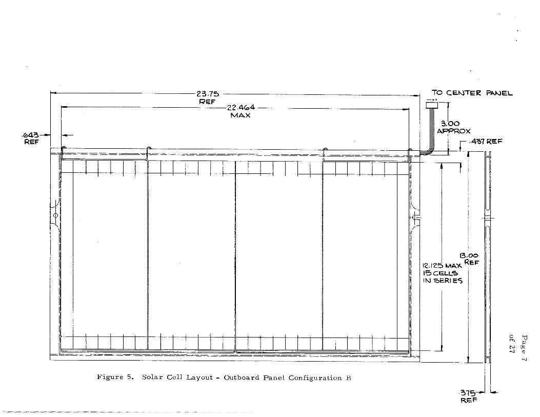
This parallel series modular concept has been selected to provide high reliability, greater simplicity in cell connections, and simplified maintenance problems. A layout of the solar panel active face is shown in Figures 4 and 5 for the outboard panels and Figure 6 for the center panels.
The panels will be wired using #24 insulated cable bonded to the substrate skin. Inter-panel wiring to the center pan.el will be imbedded in a bonding agent in the channel betwe.en the substrate skins along the t~p edge of the outboard pan~l and will terminate in a connector. Mating connectors will be located at the edge of the center panels to simplify panel interconnections as shown in Figur·e 7. The blocking diodes to prevent reverse currents in the solar panels will be located on the backside of the center panel substrates as shown in Figure 7. ']hree paralleled blocking diodes will be provided for each series string to yrovide higher reliability by redundancy. The solar array connects to the PCU through a connector which mates with the one existing on the present 'PCU.
Figure 8 shows a block diagram of the complete EASE-PSEP solar array. The input to the PCU is regulated at 16.2 volts. The solar arry is designed to account for a . 7 volt diode drop and a 1 volt line drop at full load.
3. 0 DESIGN ANALYSIS
The solar panels are designed to meet the power requirements of the
EASE-PSEP during the first lunar day. These requirements are shown in
Table I.
REV. NO .
OF 27

Solar Cell
Figure 3 Details of Solar Cell Modules
Ohmic Strip
Solar Cell
Connecting Strip
Connection Tab
Page 5 of 27
Antireflective Coating
Cov.erglass
U. V. Reflective Coating

To C~TER ~1-JEL ~o. I':> RE.F
22.4<04 ,....,
MA)(
\
-=-;!Fe = = =i=
I I l I I I I I I I I I I I I I I I l l I 1 l T I I I I I I I I I I I I !
/
-ir
",1 II II I II II jl
II II II II ~ I I I 1 I I I I I I I I I I I I 1 l I I 1 I 1 l l 1 l
~1------------------- - -
Figure 4. Solar Cell Layout - Outboard Panel Configuration A
!---.<04~ REF
•. 437 R .EF
;r=
I' -t I' li II I~
v
~ 1-- - ~
j/
II II II II II II
11
II II II II II t==
\3.00 1'2.12.5MA.')( REF ISCE.LLS IN SERIES
- ---- n
.~l~J L REF
0 "d '""' ;1: N(JQ -..l 11)
0"
.(043 REF
23.75 REF
22.4<04 MAX
,,
I I II
f1 I ,I II II I I I I I II II II II
,, ~~ ~~-===~~=~~
Figure 5. Solar Cell Layout - Outboard Panel Configuration B
TO CENIE~ PAJ-JEL --
3_100 APPRO X
.4~1R EF
13.00
12.1'2.5 MA~ RE.F
15CELL'5 IN 'OE.RIE~
n
31SJ l REF
0 1-(j ...... p; N O'Q -.J !1l
-.J

-~4-:, REF
-
-
23-75 RE.F
Z'l.4-l4" r-4-37 RE.F MAX
r=-1 !=---=-~=~-~-=-- ==1 ~==--~-=--==-~=~-~-=-~~~-~---~ ~"---------=---~ ;= ~
II I I I I I I I I I I T 1 T I I I J I l I \' II r l 1 I I I I I I I I ~ lj r-- -r-------i,l 'I II - -t--11
j/1 1\ >--11 \-- -\--~ Fr,l
·- f.-f-r-- +---1 /-
., 1---- r---1[ II 1----- II
I' \--11 13.00
II f---- r--lj 12.125 MA.'l<. REF II 1----- -r--'1 115 C.E.LL5
11 1-----f-~~ IN ~ERIE~
,, -r--,, I, -f.- -r---1, II -I- +-II II II -I- -1----11
'I I I I I I I
i i I I \ \\ II I I l I I I I I I I l I I I I I F-- ----------------------- ----~~ n L- ---- - --- -- - -- -- ---- ------·· -- -·· -··· - ---
Figure 6. Solar Cell Layout - Center Panel 3.JL REF
0 "0 ....... Pl N(JQ -.J ro
00

'TO C.E."-!T~AL 5TA.TIO"t
TO RIGHT PA~EL 10 LEFT ~NEL -- ......
~~-~-=-~--=-~~~= --=--=---=--=o-~= ~=l=W*-~
IJ
II
jl /I
1 I ~ ~
lj ,,
II 1/
II II
11 il II
11
I' l1 II II
II 11
I Jl
II 1J
J=~~-=-~-=--~---=--=--=--~~~~~===-=====-~-=--=-~~-=--=-----=---=--=-~L
Figure 7, Diode Installation Center Panel Back Side
0 'l:J ,..... flJ NCTO -.J ro
'-.()

4 ZC> $0!,.1'\\~. <:;;.,lHJ,.S
SOLAR PANEL
I '-----~----~
4 ~ o SCI.. I\ 1'1. <: .. i;t.l-$
«il..O ~ot..AR C ~;:.~".t.. <;;"
""1-2-D S"Ot..,l\~~- C£1..1..~
4:<:.0 St:Jt..A R- C·~l-1,$'
SERIES ~DIODE
14. 0 St71..A rr:. CIJ::,U..S
( +)
INPUT VOLTAGE TO PCU. 16. 2 + 0. 2 REGULATED
...__ ____ _._ ______ J. _______ L _______ <-·> e. 1:J Ill
NOQ -.1 (t)
Figure 8. EASEP/PSEP SOLAR ARRAY BLOCK DIAGRAM
..... 0
NO. REV. NO • • . ; '.
EATM-15
~ Systems Division
EASEP jPSEP Solar Panel Development ~PA:,:G~E-==l=l=_:O:::F~2=7== Design of the EASE-PSEP Solar Panel Array
DATE
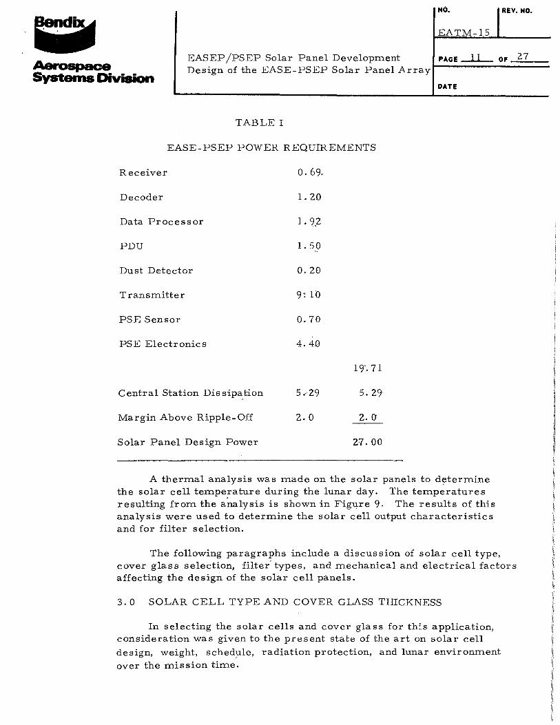
TABLE I
EASE-PSEP POWER REQUIREMENTS
Receiver o. 69.
Decoder 1. 20
Data Processor 1. 9,2
PDU 1. 50
Dust Detector 0.20
Transmitter 9: lb
PSE Sensor 0.70
PSE Electronics 4.40
19'. 71
Central Station Dissipation 5.29
Margin Above Ripple-Off 2.0 2.0
Solar Panel Design Power 2'1.00
A thermal analysis was made on the solar panels to dytermine the solar cell temperature during the lunar day. The temperatures resulting from the analysis is shown in Figure 9. The results of this analysis were used to determine the solar cell output characteristics and for filter selection.
The following paragraphs include a discussion of solar cell type, cover glass selection, filter' types, and mechanical and electrical factors affecting the design of the solar cell panels.
3. 0 SOLAR CELL TYPE AND COVER GLASS THICKNESS
In selecting the solar cells and cover glass for this application, consideration was given to the present state of the art on solar cell
design, weight, sched-ule, radiation protection, and lunar environment over the mission time.

-~ 0
til Q)
300
200
~100 ...., rO ~ Q)
0. 8 Q)
~
::::: 0 Q)
u ~ rO ....... 0
U)
-100
-200
-300
-400
--- ---, I
!
---1--- --- t:-:---- -- - .....
v v v v~ ~ ~
~ ------
1/
0 '2 IJ.I ;:;,iP ffli(
v r--
Wes~
Figu
20 40 60
~ ---~ ~
Whit( Paint ( ~ = . 2/. 9) Or Backside
e 9 - Solar Panel Tern eratures F r 60° Pane Angle
80 10.0 120 140 160 Sun Elevation Angle (Degrees)
180 ::2 {;) l.!l V')(/,)
'"d ~
OQ (1)
1-' N
0 ..... N -J

HO. REV. HO.
: ; . F:ATM-15
~ Systems Division
EASEP jPSEP Solar Panel Development PAGE 13 OF 27 Design of the EASE-PSEP Solar Panel Array J_.::.:.::...=:::::::::~::..::=::::=
DATE
Both the N/P and P /N solar cells were considered for the EASE-PSEP application. The effect of radiation on the performance of these cells is shown in Figures 10 and 11. From these curVles, it can be seen that N/P solar cells are superior for an application in which the cells will be exposed to solar flare radiation. The N/P solar cells were selected for the panel design.
Solar cells are available in a wide range of thickness; however, the . 014 nominal solar cell is considered standard by the solar cell manufacturers. Solar cell output effici'ency is a function of cell thickness as well as the res,i~tjvity of the cell. This can be seen in Figure 12. After consulting with the solar cell manufacturers and considering the above factors, the 2--ohm-cm 0. 014 thick solar cell was selected for the EASE-PSEP solar panels.
Each solar cell must be protected with a cover glass to protect it from solar flare radiation and micrometeorite damage. A solar flare analysis was made to determine the magnitude of the solar radiation expected during the mission life of six months. From this analysis a 0. 006 inch thick microsheet cover was selected.
3. 2 SOLAR CELL COATINGS
An investigation was made to evaluate the effect of blue and bluered filters and antireflective coatings on the performance of solar cells.
" Blue and blue-red filters restrict the transmission of energy in the ultraviolet region. In addition, the blue-red restricts transmission of energy in the infrared (IR) region. Antireflecting coatings are used to increase the transmission of energy in the solar cell sensitive region.
A lower operating temperature can be obtained on the solar cells with the use o.f blue-red filters which increases the voltage output of the cells. However, the blue-red filters also reduce the cell current to a greater degree than the blue filters, especially for small solar flux-panel incidence angtes. The·reason for this is that the blue-red filter lowers the effective transmittance of energy in the bandpa,ss region of the cell by shifting the IR rejection band to the shorter wave~engths. Figure 13 shows the transmission loss due to blue and blue-red filters. As can be seen from these curves, the blue-red filter with the antireflecting coating has a transmission loss of 1-1/2% more than the blue reflective filter. Cell mismatch is also greater with the blue-red filter than with the blue filter. From this analysis a blue filter with antireflective coating was selected for the solar cells.

-N
8 u ....._ n:l
8 -u en. ...
Typical 1- V Curves for Electron Bombarded P/N Silicon Solar Cells Heliotek, 1. 0 Mev electrons
Page 14
of 27
28 Beg, I.J\..-cm .---------~--------.-------~.--------.---------.---------,
0
2 x 10 3 e/cm2
16
14 2 1 x 10 e /em
12
8
4
0 0 . 1 . 2 . 3 .4 . 5 .6
Volts
Figure 10 Typical P/N Silicon Solar Cell I-V Characteristic Degradation

N
8 u -(lj 8
u U) ,.,
Page 15
of 27
Typical 1- V Curves for Electron Bombarded N /P Silicon Solar Cells B T L 1. 0 Mev Electrons MWM l...fL- em
28 .--------.--------.--------.---------r--------r--------,
24
Peak
1 X 10¹⁴ I 2 e,cm Power
20 2 X lo 14 e/cm2 Locus
3x 10 14 e /xm2
6 X 10 14 e /cm2
16 1 X 10 15 e/cm2
2 X 10 15 e/cm2
3x 10 15 e /em 2
12
15 2 6 x 10 e /em
0 ~------~------~------~~------~------~------~ .1 .2 .3 .4 .5
Volts
Figure 11 Typical N /P Silicon Solar Cell I-V Characteristic Degradation

~ -l) 0 co N ~
ell >. u c:: <1) ..... u ..... ...... ...... ~
0 til til ell
::;g J..t .....
<t:
12
11
10
9
8 .. 2 4 6 8 10 12 14 16
Cell Thickness (0. 001 ")
Figure 12 Estimated Air Mass 0 Efficiency of He1iotek Silicon Solar Cells
18
0 ~ '"" Pl N(JQ -J ro
...... 0'

104 .-----~-------.-------.------.-------~------~~---,,-----~------~
102
I I I I I ~ Uncove,ed Cell
,_. (])
g 100 ~ ..... :::! A. ..... :::! 0
(])
> ..... ..... C1l ~ (])
r:r:;
98
96
94 I I I I ' mitA 1\ ~ c;; ~ · \ w ., ,,Q tlBg I I ==:...,_ ..¢::: =:....... o:::::::l
Unc
92 I I I I I I I I I
0° 2° 4° 6° s0 106 12° 14° 16° 18°
Angle of Incidence
Figure 13 Transmission Povver Losses Associated with Various Cover Slips Cemented to a Typical Cell at 80°F
S,'"d PJ
NCJQ -.l (1)
..... -.l

NO. REV. NO.
: :.- I
EATM-15
Aerospace Systems Division
EASEP /PSEP Solra Panel Development PAGE 18 OF 27 Design of the EASE-PSEP Solar Panel Array J_:::!:...=::::::=::.....:~::::::::=
DATE
3. 2. 1 Interference Filte"r
The latest OCLI specification document is dated 1 January 1966. This document identifies the proposed cover as B-SCC-4u0-M-C with a cut-on wavelength of 400 mu (50o/o absolute transmission point).
3. 2. 2 Anti-Reflective Coating
A single layer coating will be applied to produce reflections of less than 2o/o in the wavelength region from 600 to 800 mu (per OCLI normal production quality).
3. 3 OTHER DESIGN FACTORS
Other parameters which affect the EASE-PSEP solar panel design are:
l. Transmi~sion loss through cover glas"S and filtre
2. Cell mismatch
3. Panel orientation allowance
4. UV and micrometeorite allowance
5. Solar constant variation
6. Diode loss.
Table II summarizes the factors that are used for the solar panel power output calculations. The various parameters are discussed in the following paragraph.
The transmis"sion loss through a covering filter is dependent on the cover glass thickness, the optical characteristics of the filter, and the solar incidence angle. A 6 mil cover glass with blue filter has been selected for the application for the selected design, the transmission factor is 0. 95 (i.e, 5o/o loss) at normal incidence. The variation of transmission loss with sun angle for the selected filter is shown by the separation of the "covered" and uncovered curves of Figure 13. The cover glass correction factors used in the design calculations were obtained from Spectrolab and are documented in Table Ill for a solar cell with . 006 cover glass and plue filter.

NO. REV. NO • . . : . EATM-15
Aerospace Systems Division
EASEP /PSEP Solar Panel Development ~P:AG::,:E:_::::l:::9=~o:,::F~=2=7== Design of the EASE-PSEP Solar Panel Array
TABLE II
SOLAR PANEL DESIGN FACTORS
Design Factors
Transmission Loss through glass cover slides, cement, soldering operations, assembly and mismatching losses>:<
Misorientation allowance for 5°
Solar constant variations
Diode Loss
Panel Current
.93
. 995
. 95
DATE
Panel Voltage
0.960
>:<Solar cell suppliers prefer to combine the transmission losses and mismatch losses into one value as shown.

NO. REV. NO.
EATM-15
Aerospace Systems Division
EASEP /PSEP Solar Panel Development PAGE 20 oF 27 Design of the EASE-PSEP Solar Panel Array
DATE
TABLE III
TRANSMISSION POWER LOSSES ASSOCIATED WITH SOLAR CELL COVER GLASS WITH BLUE FILTER AND AR COATING
Angle of Incidence 8
90 85 80 75 70 65 60 55 50 45 40 35 30 25 20 15 10
5
0
Relative Output Factor for Blue Reflector With AR Coating
0 . 027 . 070 .181 • 279 . 379 . 473 .558 . 635 . 711 .770 . 828 . 875 .912 .937 .965 .984 .994
1. 000
NO. REV. NO.
: : . EATM-15
~ Systems Division
EASEP /PSEP Solar Panel Development ~PA:G::E:..:::;:2::::1 =-~o:F:..::=2~7= Design of the EASE-PSEP Solar Panel Array
DATE
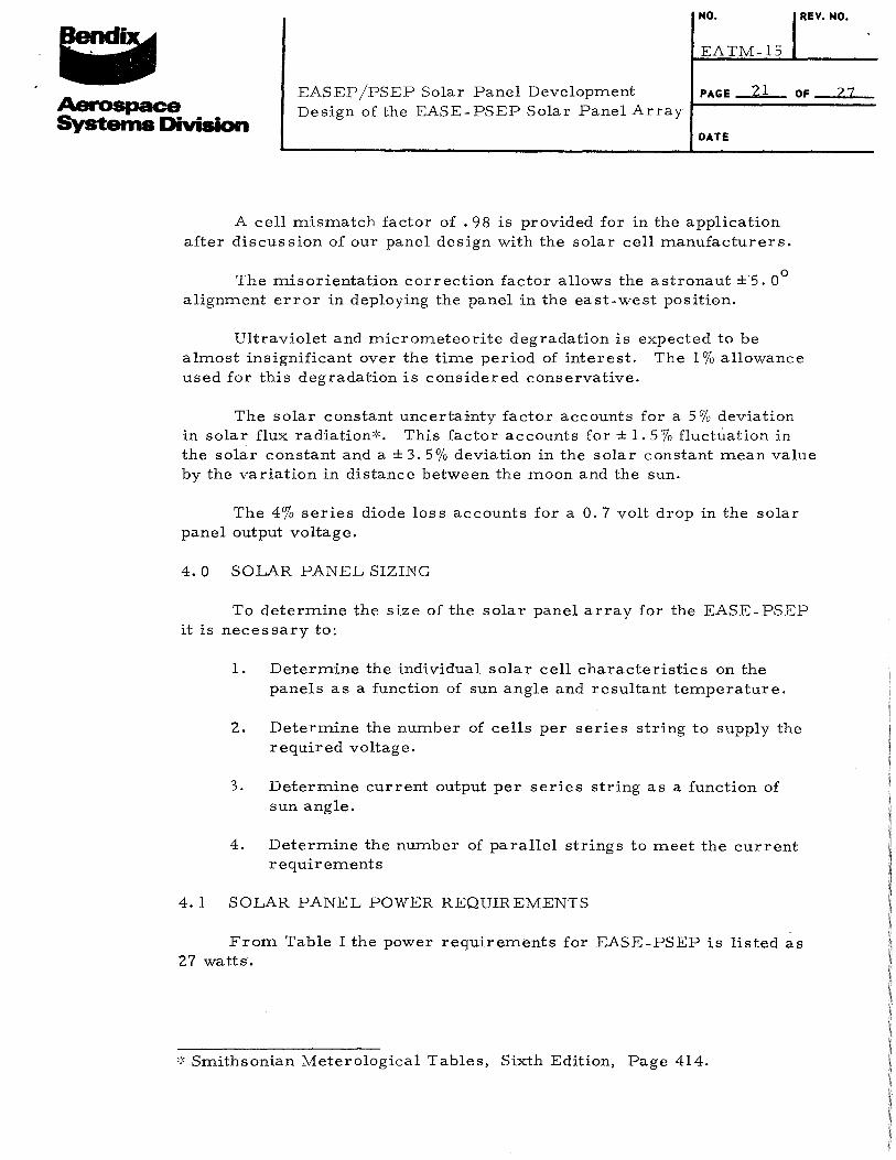
A cell mismatch factor of . 98 is provided for in the application after discussion of our panel design with the solar cell manufacturers.
The misorientation correction factor allows the astronaut ±.5. 0° alignment error in deploying the panel in the east-west position.
Ultraviolet and micrometeorite degradation is expected to be almost insignificant over the time period of interest. The 1 o/o allowance used for this degradation is considered conservative.
The solar constant uncertainty factor accounts for a 5 o/o deviation in solar flux radiation':'. This factor accounts for ± 1. 5o/o fluctuation in the solar constant and a± 3. 5o/o deviation in the solar constant mean value by the variation in distance between the moon and the sun.
The 4o/o series diode loss accounts for a 0. 7 volt drop in the solar panel output voltage.
4. 0 SOLAR PANEL SIZING
To determine the size of the solar panel array for the EASE-PSEP it is necessary to:
1. Determine the individual solar cell characteristics on the panels as a function of sun angle and resultant temperature.
2. Determine the number of cells per series string to supply the required voltage.
3. Determine current output per series string as a function of sun angle.
4. Determine the number of parallel strings to meet the current requirements
4. 1 SOLAR PANEL POWER REQUIREMENTS
From Table I the power requirements for EASE-PSEP is listed as 27 watts.
':'Smithsonian Meterological Tables, Sixth Edition, Page 414.

I NO. REV. NO.
EATM-15
~ Systems Division
EASEP /PSEP Solar Panel Development J_.:::PA::G:,:E:..=:::;2::2=~o:F..=:::::2::7:=. Design of the EASE-PSEP Solar Panel Array
DATE
From ALSEP the PCU voltage requirement is 16. 2± 0. 2 volts. Considering line losses and diode drop the solar cell series string voltage can be determined as shown in Table IV.
TABLE IV
SOLAR PANEL VOLTAGE SUMMARY
PCU input, nominal 16. 2 volts
Solar panel series diode drop ( 4%) . 3 volts
Panel wiring and cable line drop 1. 0 volts
17. 9 volts
4. 2 SOLAR CELL CHARACTERISTICS
Figure 13 presents the I-V curves with the peak power points for the selected Heli_c::>te£__f __ J.C __ ~-~!!:!~-J>J/R __ s<?lar _<::~ll as a function of temperature.
:t Using the I-V curves/a Figure 14 and the solar flux incidence
correction factors in Table III, a composite set of I-V curves can be plotted considering two solar cells in parallel (one for each side of the array). This gives a unit power output for the solar array for varoius sun angles from which to finalize the series-parallel solar cell configuration to meet the power requirements. These curves are presented in Figures 15 and 16.
4. 3 SOLAR CELL STRING CONFIGURATION
From the power requirement.s above, we find that the output of each series string of cens must be 17. 9 volts. From the I-V curves in Figures 15 and 16 it can be seen that the voltage at the critical peak power point is 323 mv per cell.
To determine the number of cells in series per string to obtain 17. 9 volts per string.
17.0 3.23 mv
= 56 cells in series minimum required. In
In order to provide voltage margin to account for temperature variations
60 cells in series is selected for the solar panel array. This results in packaging 15 cells in each section of the series string.

Page 23 I
I
~ L/5
~ urtr~tl' n~ r~ 1 s ~~
160 • 014
;r ' ~1.'- 2 . . 140 t .. !'-' MW/cm '
140
~
! ~'i
I ,_ I~
""" l=l 120 Q)
1-< 1-<
_, '
::s 0 j
100
l'l< o.o v ,....; 0!!:
80 col': "it;
v
X 0 u l:l
0 .. -~ .. .. Ill .. .. ~ .. dl
o"' ... ... o ~ 60 o:!:"
' L! -
n_ -
D -~0"' ><- " -o>< ~ ... -11
~ X
40
20
0 0 . 1 • 2 • 3 • 4 . 5 • 6 • 7 . 8 • 9 1.0
Voltage (VOLTS)

-ro E -~ (l)
'"' (') '"' ::I 0 u .... 0 10
"' ci l: u u 0:
!: '" ., Ill
.. .. ~ .. oil
0~;: 1-u"' 0~ ~ -o'" ><- " ox _,...
~ X
80
60
40
20
.T
·In
11~ 1e
s
B. ,e
Page 24 )j ") 7
++-· : ir H~ I : i j_ _ _l_j

Page 25
IP.
160 ~
140
I ~
120
~
100
«< u a ' .. -~
80 Q)
~ ~ ::;
"'"' (.)
o..; ",; o~ CD~ 60 'It> I
I
ci X u u 0:
~ .. .. ld
.. .. ~~~~oil
... .J O:r"' ... u t: 40 o!!: ::> -o., ><- " o" _,._
~ I
I
I
20
' I
I
! I
0 0
r 0 0 s e I ' ,r: li:l ,..... I\: 1-"
I • ..... ... .. "'l .......
' v

NO. REV. NO.
: ; . ~ EATM-15
~ Systems Division
EASEP jPSEP Solar Panel Development J_:PA::G::_:E:..::::2~6=:.....::o:::F-==2=7== Design of the EASE-PSEP Solar Panel Array
DATE
To determine the number of cells in parallel, it is necessary to determine current requirements
27. 0 watts minimum 16. 0 volts minimum = l. 69 amps
Considering the current degrading factors from Table II the total current required is
l. 69 amps = 0.875
l. 93 amps
From Figures 15 and 16, a minimum current of lll ma occurs at the peak power point of the critical current-voltage curve (60° curve). Using this value the number of cells in parallel to meet the power requirements are
l. 93 amps o.IT1 amps/cell
= 17. 4 or 18 cells in parallel minimum to meet power requirements.
Each side of the solar array must contain at least 18 cells in parallel sinch each side must be capable of meeting the power requirements independently during portions of the lunar day.
For the EASE-PSEP application it is convenient for panel packaging to use 21 cells in parallel and to divide these 21 cells into 3 solar cell strings, and divided into three strings. This will result in one string per panel of 60 cells in series and 7 in parallel.
5. 0 SOLAR ARRAY POWER OUT PUT
Using the curves in Figures 15 and 16, the power profile data for the completed solar array is shown in Figure 17. In this figure two curves are presented. Curve A shows 60 cells in series ?-nd 18 in parallel and is shown for reference. Curve B shows the selected design of 60 cells in series and 21 in parallel. The excess power above 27 watts is the design margin which Will be used to cover any degradation which may be caused from dust, solar flares and lunar night survival.

8 0: ,. .,
Ill ::
~ .. oil ,. ..1
Ox"' t-u ~ o:!:" ;~ ~ o" _,..
e
Page 27
lr
s
e
JO
1