earthbag construction options for …earthbagbuilding.com/pdf/ce for risky areas v1.1.pdf ·...
TRANSCRIPT

CONTAINED EARTH FOR RISKY AREAS V 1.1 EARTHBAG CONSTRUCTION OPTIONS FOR INCREASED STRENGTH
BUILD SIMPLE INC., www.BuildSimple.org
MARCH, 2018
This work is licensed under the Creative Commons Attribution-NonCommercial 4.0 International License. To view a copy of this license, visit http://creativecommons.org/licenses/by-nc/4.0/ or send a letter to Creative Commons, PO Box 1866, Mountain View, CA 94042, USA.

CONTENTS INTRODUCTION TO CONTAINED EARTH SHEET # 1 COMPARING TYPES OF CE 2 RESILIENT CONTAINED EARTH 3 ANCHORED CONTAINED EARTH 4 STRUCTURAL FRAME CONTAINED EARTH
Hands-on discussions about earthbag layout in Uganda
CONSTRUCTION DETAILS 5 A- STANDARD BARBED WIRE B- CONTAINED GRAVEL FOOTING 6 C- WIRE-BOUND FOUNDATION WALL D- REBAR SPLICE 7 E- INSERTED REBAR HOOK F- CONNECTOR LOOP G- CONCRETE FOOTING H- NAILED BARBED WIRE 8 I- CORNER PINNING J- LAPPED INSERTED REBAR 9 K- CONFINING GRADE BEAM L- STRUCTURAL FRAME 10 M- TIED BARBED WIRE N- WOVEN BARBED WIRE O- INTEGRAL CORNER PINNING 11 P- SANDWICHED REBAR RING Q- REINFORCED CONCRETE MINI-RING R- SANDWICHED STEEL RING S- INTERIOR WOOD GRADE BEAM 12 MORE WAYS TO REINFORCE CE

INTRODUCTION DEFINING CONTAINED EARTH Contained earth (CE) is a special type of earthbag construction built with:
· Cohesive soil fill of estimated strength · Reinforcement chosen for specific levels of hazard · Consistently damp fill that is tamped in place
Most CE relies on two types of steel:
· Barbed wire- two strands between each course · Steel rebar inserted into damp walls
Photo by Christian Ernstsen of a pinned corner house in Uganda
As a relatively new building material, earthbag benefitted from the knowledge and vocabulary of adobe construction. Because contained earth is taking this material into a new arena of architectural and engineering analysis, terms must be clearly defined. One purpose of this document is to illustrate and label different techniques so that engineers and designers can more easily discuss, specify, and research them.
WHERE IS CONTAINED EARTH NEEDED? Earthbag construction has accelerated during the last decade because of its affordability and low-tech construction process . It has now been built in most parts of the world, including seismic risk regions. According to earthbag expert Owen Geiger, more than 4 dozen single story earthbag buildings survived through Nepal’s 2015 earthquakes, at most with minor plaster damage. Many of them were close to destroyed or seriously damaged unreinforced masonry buildings.
These Nepali earthbag buildings resisted 50- 75% of the maximum force that buildings are required to resist by Nepal’s building codei. Quake ground motion is usually described in building codes and seismic assessments by the maximum rate at which horizontal motion accelerates. The earthbag buildings’ locations received at most 0.6- 0.8 g peak ground accelerationii (pga). This is impressive, but who knows how much extra care was used in these buildings?

For comparison, some regions in Nepal experienced as much as 1 g or 1.2 g in the 2015 quakes, and the damaging 1994 Northridge earthquake in California had a maximum recorded horizontal pga of 1.8 g.
Homes are needed by those who cannot afford to build to resist an earthquake that may not occur for 80 years or many generations. The level of earthquake to resist is a difficult choice. Community buildings often resist higher forces to be available after a disaster.
Europe, Australia, and North America have access to online, detailed maps of seismic risk. For other areas, the white areas of the maps at rightiii show approximately where seismic hazard is low (available online).
Ordinary mud-brick buildings can be damaged at 0.2 g forces. But unspecified earthbag buildings should be relatively safe, because they are more ductile and less susceptible to brittle collapse than unreinforced mud-brick or brick buildings.
Light gray areas have a seismic hazard comparable to earthquakes that often destroy mud-brick buildings and cause great damage. In these areas earthbag should be built with care for modest-sized one-story residences. Most experienced earthbag builders know not to use very weak soils, but inexperienced builders can make serious mistakes in their building layout and soil choice. Weak soil earthbag can be half the strength of unreinforced adobe. Above 0.4 g risk resilient contained earth will give more reliable strength than general earthbag guidelines.
New Zealand’s earthen building guidelines help amateurs plan unreinforced adobe buildings for areas with up to 0.56 g risk. With strong soil fill and inserted rebar reinforcement, some limited testing shows that contained earth wall strengths range between those of unreinforced and reinforced adobe walls.
New Zealand’s risk levels may extend as high as 1.7 g. Preliminary tests show high-strength soil contained earth walls with intensive reinforcement may have shear strength equivalent to New Zealand’s reinforced adobe walls. But results from large scale testing are needed1.
1 By summer 2018, results should be available from four 80% scale wall tests at Santa Clara University.

Exact seismic risk levels in high hazard regions are often disputed. If the map shows dark gray or black, ask an expert to estimate the local level of risk.
COMPONENTS FABRIC TYPE AND SHAPE: Conventional earthbag and most CE is modular, with fabric separating courses.
The fabric serves as a flexible formwork until soil fill hardens. It holds the fill in place while it is tamped to consolidate the fill. In case of damage to the wall, the fabric can also serve as containment to prevent any wall material falling out. Strong polypropylene fabric probably contributes some strength acting against shear and out-of-plane forces because inserted steel reinforcement pierces multiple layers of bags.
Solid CE (a.k.a. hyperadobe) is formed in mesh tubing with enough fill moisture to create a monolithic wall between courses. Solid CE shows higher strength than modular, but may have less resilience. Mesh tubing probably contributes some increased strength to its soil fill if the fill extrudes slightly to embed the mesh.
Earthbag can be built of separate bags or long tubes. Long tubes resist some types of damage better than bags and are recommended for CE.
SOIL STRENGTH Most earthen walls transfer forces across the entire cross-section of the wall. Because earthbag has very low friction for fabric-to-fabric surfaces, forces are transferred from barb points or embedded rebar to dried soil fill embedding them. The total of these surfaces is much more limited than the area of masonry bedding joints, so a good dried soil strength has significant effect on the wall strength. Below: Soil test equipment for lever crushing
Check strength of building soil by drying 30 mm balls or 40 mm (1.5”) diameter cylinders and standing on them. Make cylinders out of a half length of toilet-paper tube. Dry the samples in a low-temperature oven.
Minimum strength for contained earth: Strong soil:
Ball crushes under full weight of 60 kg (132 lb) resists 60 kg (132 lb) person person wearing soft shoes standing on a piece of wood
Cylinder crushes under 84 kg (185 lb) on wood resists 133 kg (293 lb) on wood
More information about field soil testing to estimate compressive strength with minimal equipment is online (see 'How Strong is my Building Soil?').

Although contained earth can be compared in some ways to soil bags, compressive strength of dried cohesive wall material can reach higher levels than loose fill materials which are limited by the tensile strength of the fabric. Contained sand and contained gravel rely on fabric strength for compressive strength.
PLASTER CE walls are plastered to resist sunlight decaying the bags or tubes. A plaster embedded on a light mesh (plastic bird or fish net or better) tied to the structural barbed wire or to vertical strapping adds significantly to wall strength.
REINFORCEMENT Reinforced walls require a fully interconnected framework. For less damage under seismic motion heavy earthen walls need vertical steel that is base-anchored to a footing and embedded in or anchored to a strong bond beam.
One interesting consideration is that any reinforcement using entire long rebar from roof to footing can easily prevent lightning accidents. Use an additional piece of rebar or buy a custom grounding rod. Hammer it into the ground next to the reinforcing steel and attach them together with a grounding clamp.
Contained earth seems to be unlikely to collapse, but it is very deformable. It is highly ductile. Reinforcement may be chosen to brace walls and reduce serviceability limits to its use. Reinforcement may also be chosen to allow flexibility in connections to allow vibration damping. The types and amounts of stresses on upper and lower walls are quite different, and this field needs talented engineers to apply laboratory strength information which is being developed.
STRESS LOCATIONS Unreinforced mud-brick buildings suffer damage at specific locations. Earthbag buildings can suffer similar damage.
If barbed wire runs continuous around corners and soil fill is strong, corners may gap but severe corner damage resulting in wall overturning is unlikely. From test results to date, the other types of damage are very likely during a severe earthquake: toppling of earthbag gable walls or chimneys, racking of walls from rectangular to diamond-shaped, x-cracks in plaster and loss of wall shear strength, and long walls bulging out.
Right: Typical damage to unreinforced mud-brick buildings, after Cenaprediv

Below: Higher stress areas for earthbag buildings
Wise designers relate the amount of reinforcement to the thickness of the walls (their weight) and to their height. The use of a heavy roof or a loft floor should also be considered, and the spacing of bracing walls.
To prevent common types of damage from severe quake forces, designers can also intensify reinforcement where stress on the building will be predictably higher.
Force on walls during an earthquake is multiplied by the distance from the ground. If diagonal rebar pins are used at 60 cm (24”) centers to attach the bond beam, the top few courses are stronger than those below. Since the weight of the wall itself increases friction closer to the ground, stresses are often highest several courses from the wall top. Target maximum reinforcement just below this level.
Options for specific groups of courses include more rebar and/ or barbed wire, extra attachments to barbed wire like nails, mesh pins or tying, strengthened soil, or including entire courses of mesh tubing for solid CE (stiffer than modular CE).
CHOICES Many authors and trainers give excellent information about earthbag. Many teach or build quality structures. People with few resources will be safer in an earthbag structure than in an unreinforced mud-brick or stone building.
But as long as earthbag is not defined, there is no way for building designers and engineers to ensure a specific level of strength. When a community invests in a school or clinic or community center, they may want to know what level of seismic risk their building will be able to resist. They may choose to invest a little more time and/ or money to produce a building that will be useful even after a natural disaster.
The options that follow give them a wide range of choices that will modify building resistance to earthquake vibration significantly.
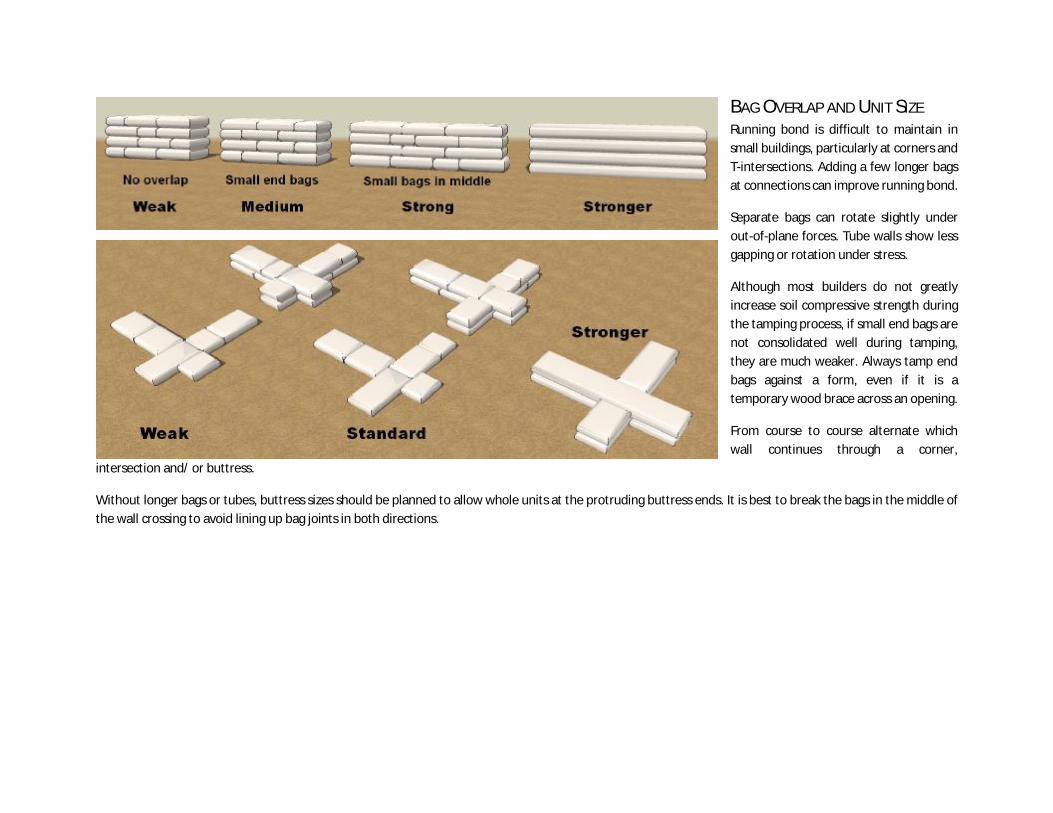
BAG OVERLAP AND UNIT SIZE Running bond is difficult to maintain in small buildings, particularly at corners and T-intersections. Adding a few longer bags at connections can improve running bond.
Separate bags can rotate slightly under out-of-plane forces. Tube walls show less gapping or rotation under stress.
Although most builders do not greatly increase soil compressive strength during the tamping process, if small end bags are not consolidated well during tamping, they are much weaker. Always tamp end bags against a form, even if it is a temporary wood brace across an opening.
From course to course alternate which wall continues through a corner,
intersection and/ or buttress.
Without longer bags or tubes, buttress sizes should be planned to allow whole units at the protruding buttress ends. It is best to break the bags in the middle of the wall crossing to avoid lining up bag joints in both directions.

BARBED WIRE CONFIGURATION The barbed wire is the reason that test walls don’t collapse.
Barbed wire is bouncy and can inflict injury. But each barb can resist about 20 kg (44 lbs) of force. Spread over barbs every 5” in length on two strands per course, it creates a fine grain of significant tensile strength to hold walls together.
Barbed wire should never end at wall openings or corners. Overlap wire more
than the wall width, and at least 1 m (39”) from corners or openings.
Barbed wire holds walls together when it is straight and taut. Always run wire straight.
An easy way to lay barbed wire more straight and taut is to use either nails or wire mesh pins where the wire turns. Wire mesh pins are made by cutting a short strip of galvanized metal mesh. Leave 3 or 4 teeth in this tiny comb. Just before placing them on a wire, bend so that the pin will
not flatten under the next course.

Tied wire reduces possible gaps under severe stress at wall corners, and can be done with any strong poly cord.
The easiest way to keep wire taut and reinforce wall ends or intersections is by weaving the wire up to the next course.
Do not weave barbed wire at corners (too many strands will interfere with barbs grabbing the bag fill and get in the way of rebar). Weave only one strand per course, alternating sides to avoid messy wire.
Barbed wire does not bond well with bags filled with loose materials like gravel, sand, weak silt or dry soil. Gravel bags have higher friction than bags filled with soil, because of their uneven surface, but some force to contain them is needed.
Reinforced concrete footings can span across places where supporting subsoil cracks or erodes away. Binding wire can help to prevent the buckling of foundation walls made of separate bags if no concrete footing is used. Giftwrap the foundation courses below the interior floor level to fully use the strength of barbed wire.

REINFORCEMENT LOCATIONS When short rebar lengths are overlapped, the upper and lower rods move independently. If the rebar are placed too close together (in plan view) stress from the upper rod will break embedded soil away from the lower rod and weaken its contribution to wall strength.
Diagonal steel can better resist horizontal wall pressure than vertical steel. Use staggered barbed wire to make room for extra inserted diagonal rebar near corners.
Rebar inserted in a damp earthen wall shows better stiffness and strength than pinning rebars used outside of the wall fill material. This may be because the steel alone can buckle under twisting force.
A good combination is to include some entire vertical pinning rebar (to hold the wall together vertically) with some overlapped inserted rebar (for better strength against racking).
External pinning tied together across the wall may be stronger. Use a lighter steel rod that hooks around the vertical steel. Remember that ties can be in the way of inserted rebar.
Vertical rebar can easily be embedded in half the courses if it is located in the joint between bags. Every other course, slit the bag and slide the bag around the steel. The soil fill will close around the rebar. In addition, vertical steel partially within the wall can have barbed wire attached.

TYPES OF CE WALLS The details that follow show many different ways to use contained earth. Some allow the use of stabilized fill, some are more costly, others cheap but require more care. Many factors can influence the best wall details.
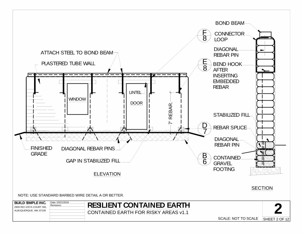
Resilient walls are most like traditional earthbag. They have little resistance against uplift. Uplift is more damaging to buildings with narrow wall panels between frequrent openings than it is to building walls much longer than high.
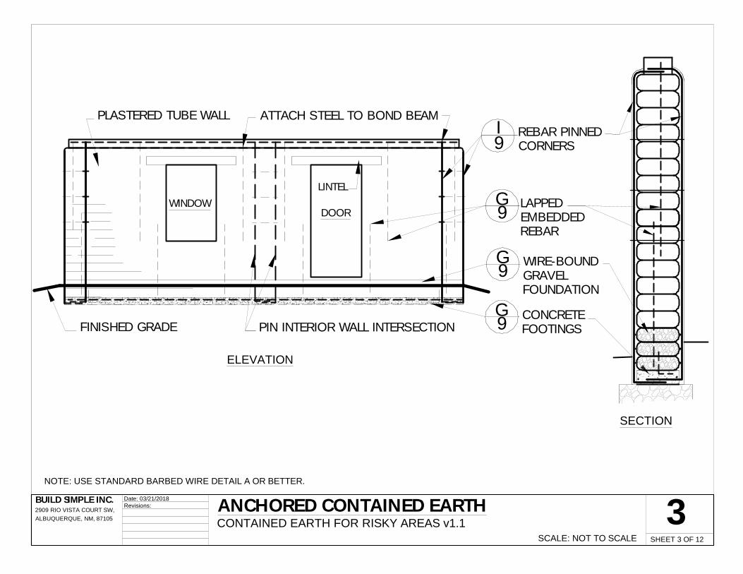
Anchored walls have better resistance against uplift. They have added stiffness from vertical steel embedded in concrete splices, spot footings, or an entire reinforced concrete footing.
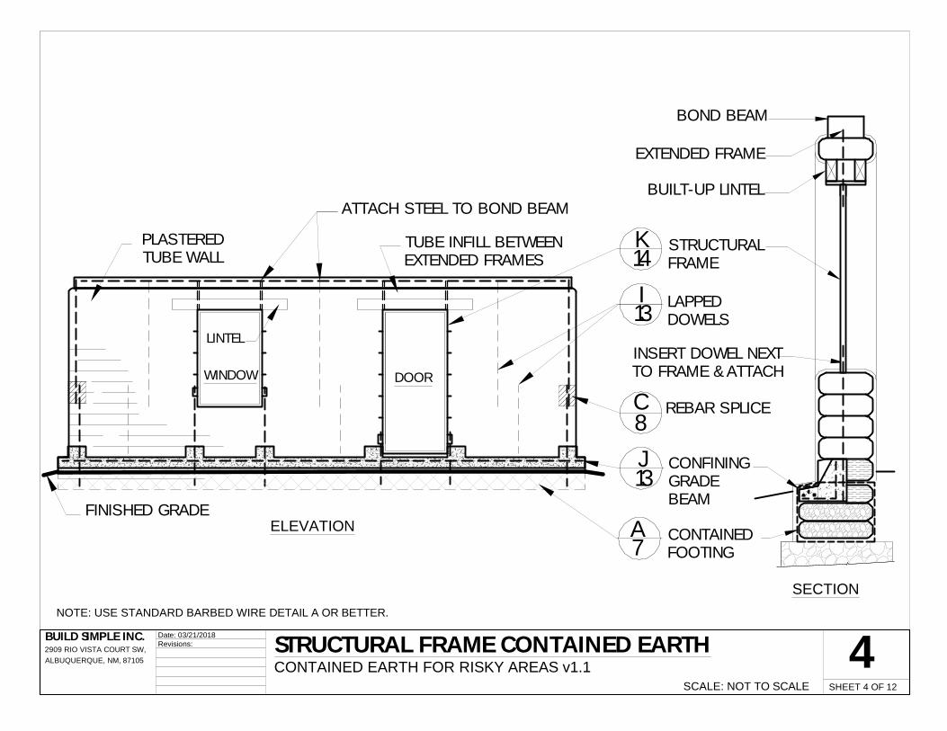
Structural steel walls take advantage of welded steel pipe frames which aid builders find less costly than wood window or door bucks. The stiffness of quality welded steel frames may be just what contained earth needs to reduce its tendency to warp under stress.
Contained earth is still being explored, but component and 60% scale experiments have shown very clearly which details have more strength than others.
This manual is dedicated to the many builders who carry earthbag wherever the need is greatest, which often is in hazardous regions.
This booklet will be updated as more information becomes available. Build Simple Inc. welcomes assistance, or suggestions in this process. Please email [email protected] with comments, construction photographs, or engineering information.
Photos: Top- structural steel in Nepal, right- builders in China inserting long rebar by Christian Ernstsen
i Nepal Department of Urban Development and Building Construction (1994) Nepal National Building Code NBC 105: 1994, Kathmandu Nepal Seismic Zone Map 14. Online at http://www.dudbc.gov.np/uploads/default/files/c25f315ba97fe50b056e7803296704b5.pdf ii Bauhaus Universitat Weimer Earthquake Damage Analysis Center (undated) Earthquake of Gorkha (Nepal) Online at http://www.edac.biz/ iii Developed by Build Simple Inc. based on short period pga predictions for cities contained in the US Army Corps of Engineers’ Unified Facilities Criteria and adapted to the general risk map outlines of the Global Seismic Hazard Program maps. iv CENAPRED, 2000. Métodos de Refuerzo para la Vivienda Rural de Autoconstrucción (Reinforcement Methods for Self construction of Rural Housing), México City, Mexico

REBARSPLICE
CONTAINEDGRAVEL
FOOTING
WIRE-BOUNDGRAVEL
FOUNDATION
CONCRETE FOOTING
LAPPEDINSERTED REBAR
ATTACH REBARTO FRAME
REBARSPLICE
CONFININGGRADE BEAM
CONTAINEDGRAVEL
FOOTING
EXTERIORCONNECTOR
LOOP
NSERTEDREBAR HOOK
EXTERIORPINNING REBAR
AT CORNERS
FRAMEEXTENSION
STRUCTURALWINDOW
FRAME
1Date: 03/21/2018Revisions: TYPES OF CONTAINED EARTH
CONTAINED EARTH FOR RISKY AREAS v1.1 SCALE: NOT TO SCALE
RESILIENT CE· FLEXIBLE CONTAINED
FOOTING· STEEL LINKED FROM
FOOTING TO BOND BEAMAGAINST UPLIFT
· STEEL CONNECTIONSFLEXIBLE
SHEET 1 OF 12
BUILD SIMPLE INC.2909 RIO VISTA COURT SW,ALBUQUERQUE, NM, 87105
ANCHORED CE· REINFORCED FOOTING OR
GRADE BEAM· STIFF REBAR CONNECTIONS
AT BASE AND TOP· SOME STEEL ENTIRE OR
RIGIDLY CONNECTED
STRUCTURAL FRAME CE· INCREASED RIGIDITY· LESS CONCRETE· REINFORCED GRADE BEAM
ON CONTAINED FOOTING· STIFF REBAR
CONNECTIONS AT BASE,MID-WALL, LINTEL AND TOP
WINDOW
PLASTERED TUBE WALL
7' R
EBA
R.
FINISHEDGRADE
DIAGONAL REBAR PINS
LINTEL
DOOR
ATTACH STEEL TO BOND BEAM
GAP IN STABILIZED FILL
BOND BEAM
CONNECTORLOOP
BEND HOOKAFTERINSERTINGEMBEDDEDREBAR
REBAR SPLICE
DIAGONALREBAR PIN
CONTAINEDGRAVELFOOTING
DIAGONALREBAR PIN
STABILIZED FILL
2Date: 03/21/2018Revisions: RESILIENT CONTAINED EARTH
CONTAINED EARTH FOR RISKY AREAS v1.1 SCALE: NOT TO SCALE
B
E
NOTE: USE STANDARD BARBED WIRE DETAIL A OR BETTER.
F
SECTION
ELEVATION
8
8
6
SHEET 2 OF 12
BUILD SIMPLE INC.2909 RIO VISTA COURT SW,ALBUQUERQUE, NM, 87105
D7
PIN INTERIOR WALL INTERSECTIONFINISHED GRADE
WINDOW
PLASTERED TUBE WALL
LINTEL
DOOR
ATTACH STEEL TO BOND BEAMREBAR PINNEDCORNERS
LAPPEDEMBEDDEDREBAR
CONCRETEFOOTINGS
WIRE-BOUNDGRAVELFOUNDATION
3Date: 03/21/2018Revisions: ANCHORED CONTAINED EARTH
CONTAINED EARTH FOR RISKY AREAS v1.1 SCALE: NOT TO SCALE
G
SECTION
ELEVATION
9
SHEET 3 OF 12
BUILD SIMPLE INC.2909 RIO VISTA COURT SW,ALBUQUERQUE, NM, 87105
G9
G9
I9
NOTE: USE STANDARD BARBED WIRE DETAIL A OR BETTER.
TUBE INFILL BETWEENEXTENDED FRAMES
FINISHED GRADE
WINDOW
PLASTEREDTUBE WALL
DOOR
ATTACH STEEL TO BOND BEAM
LINTEL
BUILT-UP LINTEL
STRUCTURALFRAME
LAPPEDDOWELS
REBAR SPLICE
CONFININGGRADEBEAM
CONTAINEDFOOTING
INSERT DOWEL NEXTTO FRAME & ATTACH
EXTENDED FRAME
BOND BEAM
Date: 03/21/2018Revisions: STRUCTURAL FRAME CONTAINED EARTH
CONTAINED EARTH FOR RISKY AREAS v1.1 SCALE: NOT TO SCALE
A
I
C
J
K
SECTION
ELEVATION7
13
8
13
14
4SHEET 4 OF 12
BUILD SIMPLE INC.2909 RIO VISTA COURT SW,ALBUQUERQUE, NM, 87105
NOTE: USE STANDARD BARBED WIRE DETAIL A OR BETTER.
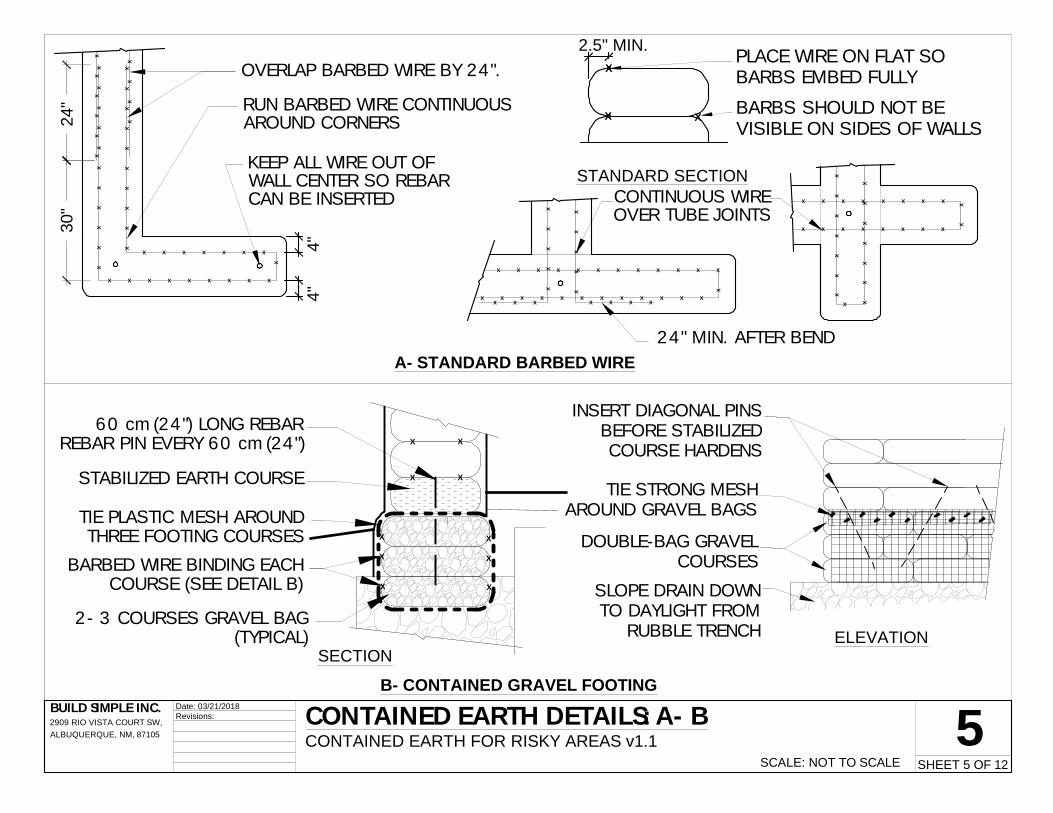
OVERLAP BARBED WIRE BY 24".
4"4"X
XX
XX
XX
XX
X
XX
XX
XX
XX
XX
XX
XX
XX
X
XX
XX
30"
24"
X X X X X X X
X X X X X X X X X
RUN BARBED WIRE CONTINUOUSAROUND CORNERS
KEEP ALL WIRE OUT OFWALL CENTER SO REBARCAN BE INSERTED
X
X X
XPLACE WIRE ON FLAT SOBARBS EMBED FULLY
BARBS SHOULD NOT BEVISIBLE ON SIDES OF WALLS
2.5" MIN.
X X X X X X X X X X
X X X X X X X X XX X X
X X
XX
XX
X
XX
XX
X
X X X X X X X
X
CONTINUOUS WIREOVER TUBE JOINTS
X X X X X X
X X X X X
X X
X X X
XX
XX
XX
X
XX
XX
XX
X
X
XX
24" MIN. AFTER BEND
TIE PLASTIC MESH AROUNDTHREE FOOTING COURSES
60 cm (24") LONG REBARREBAR PIN EVERY 60 cm (24")
2- 3 COURSES GRAVEL BAG(TYPICAL)
BARBED WIRE BINDING EACHCOURSE (SEE DETAIL B)
X X
X X
X
X
X X
X
X
STABILIZED EARTH COURSE
SLOPE DRAIN DOWNTO DAYLIGHT FROM
RUBBLE TRENCH
DOUBLE-BAG GRAVELCOURSES
TIE STRONG MESHAROUND GRAVEL BAGS
INSERT DIAGONAL PINSBEFORE STABILIZEDCOURSE HARDENS
5Date: 03/21/2018Revisions: CONTAINED EARTH DETAILS: A- B
CONTAINED EARTH FOR RISKY AREAS v1.1 SCALE: NOT TO SCALE
A- STANDARD BARBED WIRE
STANDARD SECTION
SHEET 5 OF 12
BUILD SIMPLE INC.2909 RIO VISTA COURT SW,ALBUQUERQUE, NM, 87105
ELEVATIONSECTION
B- CONTAINED GRAVEL FOOTING

OVERLAP WIRE 24" MIN.AT 36" FROM CORNERS;
TIE AT BARBS (TYP.)XX X XX X
XX X X X X X
X
XX X X X X X
X X X
X X X
1 STRAND AROUNDEACH STRAIGHT WALL
SECTION
1 STRAND WIREAROUND BUILDING
EACH COURSEBELOW FINISH FLOOR
X XX X
X
X X
X
X
XX
XX
X
XX
XX
XX
XX
X
XX
X
X
XX
XX
XX
X
XX
XX
XX
XX
XX
X
XX
XX
X
BINDING WIRE
X
X
XX X X X X X XX X X X
X X X X X X X X
X X X X X X X X X
XX X X X X X X X
XX X X X XX X X XX X
XX X X X X X X XXX X X XX X X XX
DIAGONAL REBAR PINS60 cm (24") ON CENTER
VERTICAL STRAPPING 60cm (24") ON CENTER
X
XINSERT UPPER REBAR INTO GAPFROM ABOVE
FILL WEAK MESH BAGS WITHCONCRETE. PLACE AROUND REBAR,
SQUEEZE BAGS TO JOIN FILL X
XAFTER CONCRETE CURES, ADDEARTH FILL TO LEVEL
X
X
X
X
CUT GAP IN COURSEAFTER TAMPING
INSERT LOWER REBAR
INSERT UPPER REBARINTO GAP FROM ABOVE
PACK CONCRETEAROUND STEEL
TUBE OR BAGCOURSES
10"
8"
6CONTAINED EARTH DETAILS: C- DCONTAINED EARTH FOR RISKY AREAS v1.1
SCALE: VARIES
Date: 03/21/2018Revisions:
SECTION
SHEET 6 OF 12
BUILD SIMPLE INC.2909 RIO VISTA COURT SW,ALBUQUERQUE, NM, 87105
C- WIRE-BOUND FOUNDATION WALL
ELEVATION
SECTION
PLAN DETAILD- REBAR SPLICE

INSERT STRAIGHT REBARINTO DAMP WALL
PLACE OTHER REINFORCINGSTEEL ON WALL
BEND END OF INSERTEDREBAR DOWN
TUBE WALL (TYPICAL)
PLACE U-SHAPEDLOOP UNDER REBAR
HOOK
LIFT LOOP, BENDENDS OVER TOPCOURSE AND TIETOGETHER
BOND BEAM
X
X
X
X
X X
X
X
X
X
DIAGONAL PINTHROUGH
STABILIZED COURSE
X
WIRE-BOUNDFOUNDATION WALL
REINFORCEDCONCRETE FOOTING X
X X
X
X
X X
X X
X X
EMBED REBAR PINS, PINNINGREBAR OR CONNECTOR
LOOPS IN CONCRETE
X X X X
X X X X
X
AT EACH WIRE BEND INSERT3" FINISH NAIL HALFWAY INTOBAG FILL, PULLING WIRE TAUT
LAY WIRE CONTINUOUSNEAR CORNERS, ENDS,
AND OPENINGS
X X
EMBED UPPER TUBECAREFULLY ON NAIL
HAMMER 3" FINISHING NAILHALFWAY INTO SOIL FILL
7Date: 03/21/2018Revisions: CONTAINED EARTH DETAILS E- H
CONTAINED EARTH FOR RISKY AREAS v1.1SCALE: VARIES
E- INSERTED REBAR HOOK
ELEVATION
SHEET 7 OF 12
BUILD SIMPLE INC.2909 RIO VISTA COURT SW,ALBUQUERQUE, NM, 87105
NOTE:FOR REBAR LONGER THAN 1.8 m (6'), HOLD
REBAR IN A SLIGHTLY LARGER METAL PIPETO HAMMER
SECTION
F- CONNECTOR LOOP
G- CONCRETE FOOTING
SECTION
PLAN DETAIL
SECTION
H- NAILED BARBED WIRE
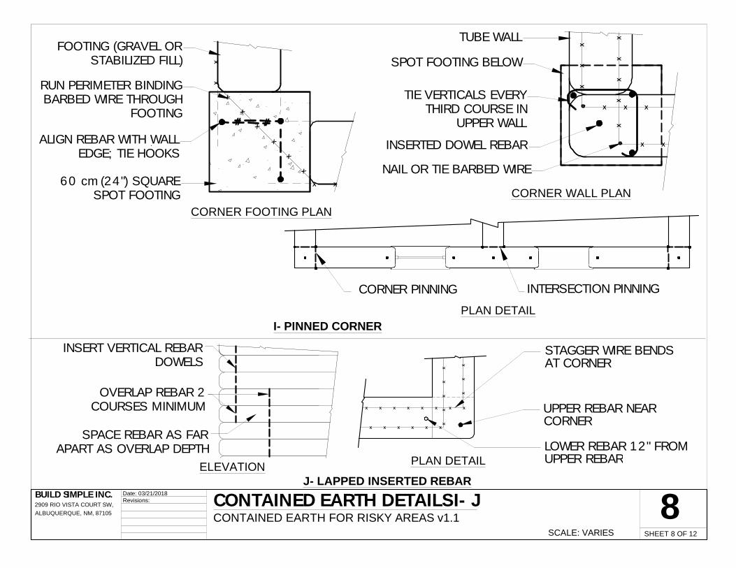
ALIGN REBAR WITH WALLEDGE; TIE HOOKS
60 cm (24") SQUARESPOT FOOTING
FOOTING (GRAVEL ORSTABILIZED FILL)
RUN PERIMETER BINDINGBARBED WIRE THROUGH
FOOTING
X
X
X
X
X
X
X X
XX SPOT FOOTING BELOW
TUBE WALL
TIE VERTICALS EVERYTHIRD COURSE IN
UPPER WALL
XX
XX
X X X
X X
XX
X
INSERTED DOWEL REBAR
NAIL OR TIE BARBED WIRE
X
SPACE REBAR AS FARAPART AS OVERLAP DEPTH
INSERT VERTICAL REBARDOWELS
OVERLAP REBAR 2COURSES MINIMUM
STAGGER WIRE BENDSAT CORNER
UPPER REBAR NEARCORNER
LOWER REBAR 12" FROMUPPER REBAR
X X X X X X
X X X X X X
X X
XX
XX
X
XX
X
CORNER PINNING INTERSECTION PINNING
CONTAINED EARTH DETAILS I- JCONTAINED EARTH FOR RISKY AREAS v1.1
SCALE: VARIES
Date: 03/21/2018Revisions:
I- PINNED CORNER
8
CORNER FOOTING PLAN
SHEET 8 OF 12
BUILD SIMPLE INC.2909 RIO VISTA COURT SW,ALBUQUERQUE, NM, 87105
CORNER WALL PLAN
J- LAPPED INSERTED REBARELEVATION PLAN DETAIL
PLAN DETAIL

POUR CONCRETEGRADE BEAM AFTERALL STEEL IS PLACED
5"
TIE REBAR ANCHOR TOINSERTED REBAR
PACK CONCRETEAROUND STEEL
ENCIRCLE COURSES INHEAVY MESH AND TIE
X
X
X
X
X
X
X
X
X
X XX X
X
FOUNDATION ORFOOTING
10"
8"
15" 20"
CUT GAP AFTER PLACING& TAMPING TUBE COURSE
REINF. CONCRETE GRADE BEAM
INSERT REBAR ABOVE GAP 150mm (6") FROM EDGE OF WALL
WELDED WINDOW FRAME OFRECTANGULAR STEEL PIPE
INFILL TUBES BETWEEN FRAMES
ATTACH WIRE TO SPURS
ATTACH REBAR TO FRAME
VELCRO PLATE (TYPICAL)
ATTACH FRAME TO BOND BEAM
BUILT-UP LINTEL BUILT-UP LINTEL
WALL OPENING
STRUCTURAL FRAME
WEAVE BARBED WIRE TO NEXTCOURSE AROUND REBAR SPUR
INSERT REBAR & ATTACHTO FRAME
EXTENDED FRAME, ATTACHREBAR TO FRAME, OR USE
CONNECTOR LOOP)
XX
XX
X
XX
XX
XX
CONTAINED EARTH DETAILS K- LCONTAINED EARTH FOR RISKY AREAS v1.1
SCALE: VARIES
Date: 03/21/2018Revisions:
K- CONFINING GRADE BEAMSECTION
9SHEET 9 OF 12
BUILD SIMPLE INC.2909 RIO VISTA COURT SW,ALBUQUERQUE, NM, 87105
PLAN
L- STRUCTURAL FRAME
ELEVATION SECTION

WIRE CONTINUOUS NEAR ENDS, CORNERS
X X X X X X
X X X X XX X X X X X X X
X X X X X X X
X X
X
XX
XX
XX
XX
XX
XX
XX
XX
XX
XX
X
XX
XX
X
XX
X
XX
X
XXXX
XXX
X
X
XTIE STRONG CORD TO BARB
AT REMAINING BEND
TIE CORD FROM LOWERCOURSE TO WIRE ABOVE
SLIT TUBE TO EMBED REBAR INSOIL FILL
CONFINING GRADE BEAMBELOW
TUBE WALL
TIE VERTICAL REBAR
XX
X
X X X
X X
XX
X
X
XBARBED WIRE AROUNDVERTICAL REBAR
SPOT FOOTINGINTEGRAL WITH
CONFINING GRADE BEAMOR CONCRETE FOOTING
VERTICAL REBAR
PULL WIRE TAUT &ONTO COURSE ABOVE
X X X X X
X X X X XX X X X
X X X X XX X X X X XX
XX
X
X
XX
X
XX
XX
XX
WEAVE WIREALTERNATE SIDES
30" EXTRA WIRE
WEAVE ONE OF EACHPAIR OF STRANDS
X X X X X X X X
X X X X X X X X X
XXXXXX
XXXXX
X X
X X X X X
XX
XXX
XX
XX
XX
X
XX
XX
XX
X
XX
XX
XX
XX
XX
XX X
X X X
X
XX
XX
X X X X
X
XXX
XX
XX
X
XXXXXXXXX
CONTAINED EARTH DETAILS M- OCONTAINED EARTH FOR RISKY AREAS v1.1
SCALE: VARIES
Date: 03/21/2018Revisions: 10
PLAN DETAILS
M- TIED BARBED WIRE
SHEET 10 OF 12
BUILD SIMPLE INC.2909 RIO VISTA COURT SW,ALBUQUERQUE, NM, 87105
PLANSECTION
O- INTEGRAL PINNED CORNER
N- WOVEN BARBED WIRE
PLAN DETAILS
SECTIONELEVATION

BEND INSERTED REBAR OVERAND ATTACH TO RING REBAR
TUBE COURSE
2 COURSES SOLID CE (BUILTDAMP ENOUGH TO SOLIDIFY
BETWEEN COURSES)
THREAD STRIP OF PLASTICMESH ON RING BEAM REBAR
X
X
X
BEND TOP OF REBAR
MODULAR CONTAINEDEARTH COURSE
TWO COURSES OF SOLID CE
ATTACH REBAR TO 1.5 x 3"STEEL PIPE CONTINUOUS
TAMP HOLLOW IN MESHTUBE COURSE
INSERT STAINLESS NAILSEVERY 300 mm (12")
POUR CONCRETEAROUND REBARS
2 COURSES SOLID CE
3"
6"
INSERTED REBAR
XX
X
X X
XX
X X
FINISHED FLOOR LEVEL
CLAMP REBAR HOOKSTO WOOD GRADE BEAM
DEFORM HEADS OFDIAGONAL REBAR PINS
SPLICE IN GAP
LOCATE BEAM AND ATTACHBEFORE COURSE HARDENS
INSERTED REBAR
CONTAINED EARTH DETAILS P- SCONTAINED EARTH FOR RISKY AREAS v1.1
SCALE: VARIES
Date: 03/21/2018Revisions: 11
P- SANDWICHED REBAR RING
SHEET 11 OF 12
BUILD SIMPLE INC.2909 RIO VISTA COURT SW,ALBUQUERQUE, NM, 87105
SECTION
R- SANDWICHED STEEL RING
Q- REINFORCED CONCRETE MINI-RING
SECTION
S- INTERIOR WOOD GRADE BEAM
SECTION
SECTION

12Date: 03/21/2018Revisions: MORE WAYS TO REINFORCE CONTAINED EARTH
CONTAINED EARTH FOR RISKY AREAS v1.1 SCALE: NOT TO SCALE SHEET 12 OF 12
BUILD SIMPLE INC.2909 RIO VISTA COURT SW,ALBUQUERQUE, NM, 87105
FOOTING CONNECTOR, RING & DIAGONALS
TRUSSED UPPER WALL CONNECTOR LOOPS
PINNED CORNER WITH DIAGONAL DOWELS
CORNER TRUSSES