earth mat design for metro station
TRANSCRIPT

Earth Mat Design for Metro Station
Subhendu Bikash SantraSE/RVNL/KOLKATA

contents
Introduction.
Standards.
Design Procedure.
Example.

Introduction
Earthing means connecting one conducting wire from neutral point to ground [System Grounding] or from equipment body to ground [ Equipment grounding].
Earthing system is necessary to ensure safety of equipment and personnel, continuity, protection and reliability of overall system.
Separate Earth or Clean Earth.
Earth Mat.

Standard
IS 3043:1989.
IEEE 80:2000.

Purpose of Earth-MAT
Provides easy and shortest path to flow the earth fault current without adversely affecting the continuity of service.
Safe touch and step voltage for personnel nearby the station area.
Protection of costly devices from unbalanced voltage during fault.

Design Procedure of Earth Mat
Determination of maximum L-G fault current and L-L-G fault current at LT side. Take the larger one as fault current for MAT design.
Determine the grid current by using current split factor.
Buried conductor size selection .
Select Design according to the space availability.
Design Procedure of Earth Mat
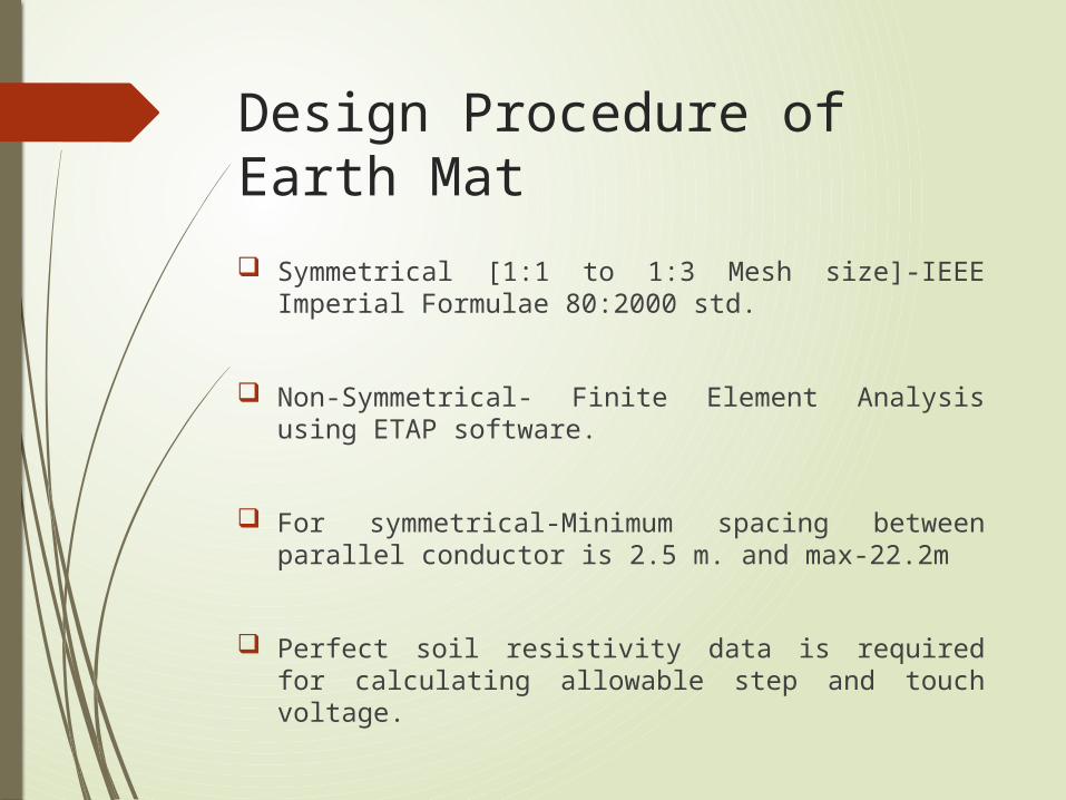
Symmetrical [1:1 to 1:3 Mesh size]-IEEE Imperial Formulae 80:2000 std.
Non-Symmetrical- Finite Element Analysis using ETAP software.
For symmetrical-Minimum spacing between parallel conductor is 2.5 m. and max-22.2m
Perfect soil resistivity data is required for calculating allowable step and touch voltage.

Design Procedure of Earth Mat
A high soil resistivity of crust layer is required where soil resistivity is very high and fault current is large.
Where soil resistivity is low there is no need of giving high resistivity crust layer.
Crust layer resistivity directly increases the allowable touch and step potential without actually reducing calculated touch and step voltage.
Two layer soil model is required where soil resistivity is non-uniform.
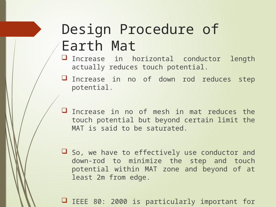
Design Procedure of Earth Mat Increase in horizontal conductor length actually
reduces touch potential.
Increase in no of down rod reduces step potential.
Increase in no of mesh in mat reduces the touch potential but beyond certain limit the MAT is said to be saturated.
So, we have to effectively use conductor and down-rod to minimize the step and touch potential within MAT zone and beyond of at least 2m from edge.
IEEE 80: 2000 is particularly important for symmetrical MAT design where space is not a problem.
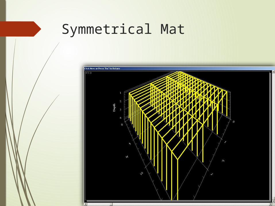
Symmetrical Mat

Unsymmetrical MAT

Example : JOKA Station
Space Availability : Non-Uniform
Soil Resistivity: Non-Uniform. (7.60 ohm-m[6M] and 12.88 ohm-m (beyond 6M).
Fault Current: 7.5 KA (max)
Split Factor: 75%
Crust layer treatment : Nothing is required as soil resistivity is less and also fault current.

Example : JOKA Station
Method : Finite Element Analysis Method.
Analysis: ETAP software.

Proposed Drawing at JOKA
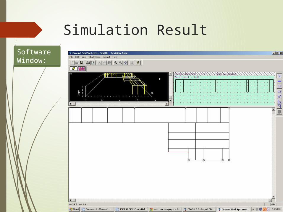
Simulation Result
Software Window:Software Window:

Simulation Result
MAT ModelCorelated with spaceavailability
Simulation Result
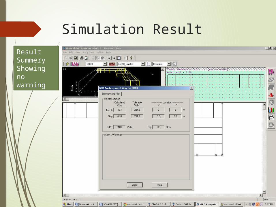
Result SummeryShowing no warning
Simulation Result
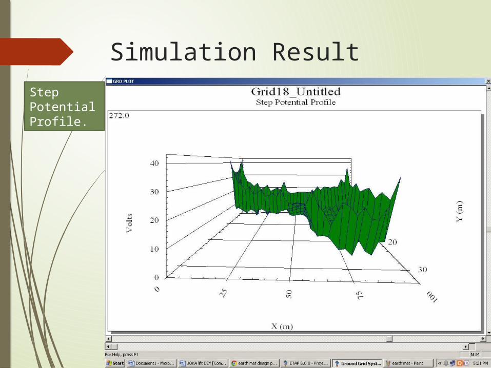
Step Potential Profile.
Simulation Result
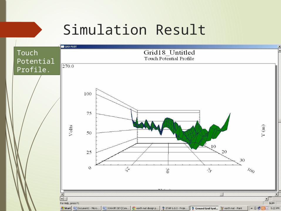
Touch Potential Profile.

Simulation Result
Grid Potential Rise

Simulation Result
Allowable Step: 231.8 V ; Calculated Step: 41.6 V
Allowable Touch: 224.5 V ; Calculated Touch: 103 V
Resistance : 0.09 Ohm (less than 1 ohm)
GPR: 510.8 V which is considerably low for a remote ended person. (transferred potential)
Thus the MAT design is safe and Acceptable.

Thank You