earth coordinates & grid coordinate systems earth’s shape •the geoid is the surface which...
TRANSCRIPT
Earth Coordinates &
Grid Coordinate Systems
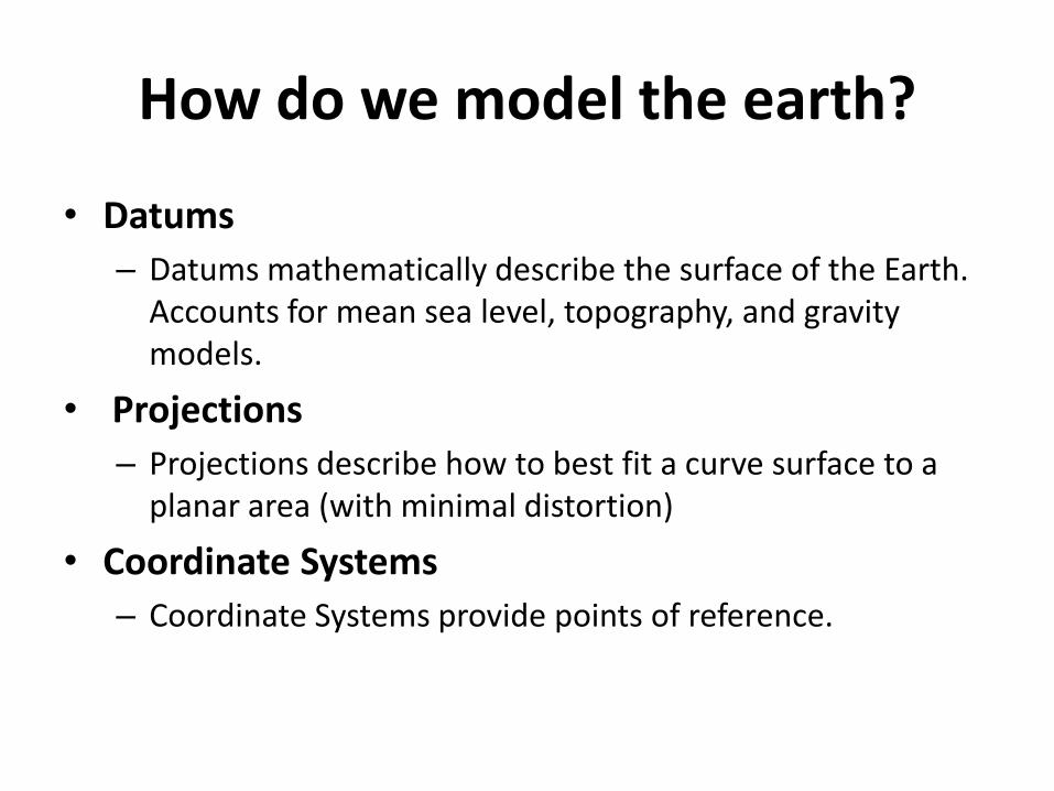
How do we model the earth?
• Datums
– Datums mathematically describe the surface of the Earth. Accounts for mean sea level, topography, and gravity models.
• Projections
– Projections describe how to best fit a curve surface to a planar area (with minimal distortion)
• Coordinate Systems
– Coordinate Systems provide points of reference.
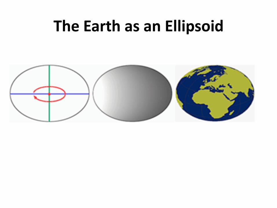
The Earth as an Ellipsoid
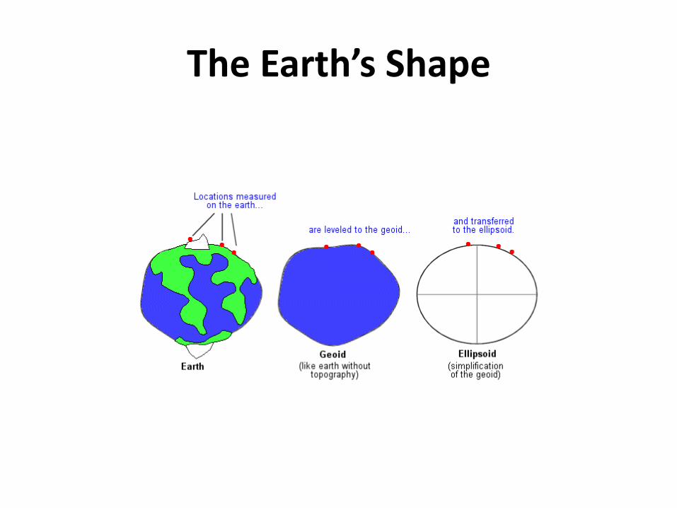
The Earth’s Shape
• The geoid is the surface which would coincide exactly with the mean ocean surface of the Earth, if the oceans were to be extended through the continents.
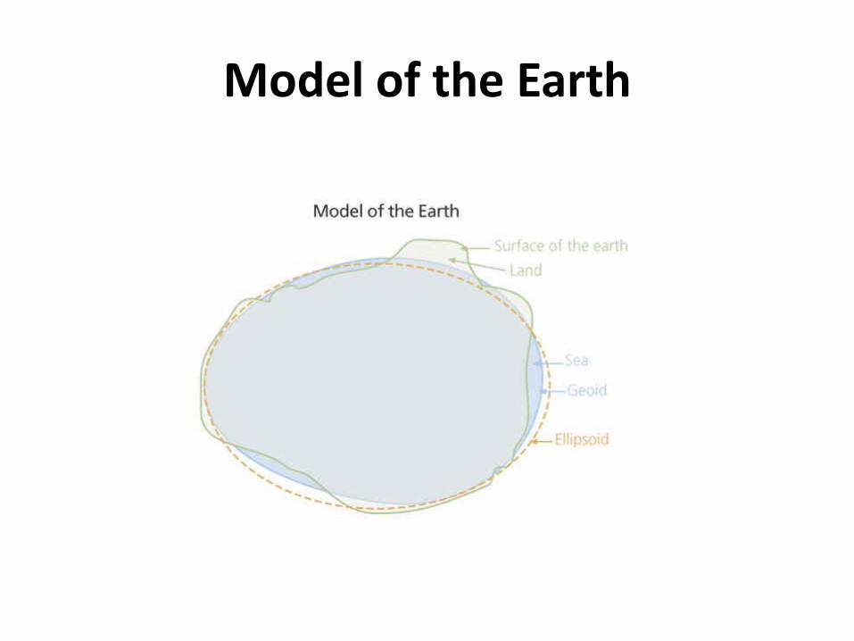
Model of the Earth
The Earth’s Shape
Definition: Datum
• A mathematical model that describes the shape of the ellipsoid
• Can be described as a reference mapping surface• Defines the size and shape of the earth and the
origin and orientation of the coordinate system used.
• There are local datums for different parts of the earth based on different measurements
• Datums are the basis for coordinate systems• Assigning the wrong datum to a coordinate
system may result in errors of hundreds of feet
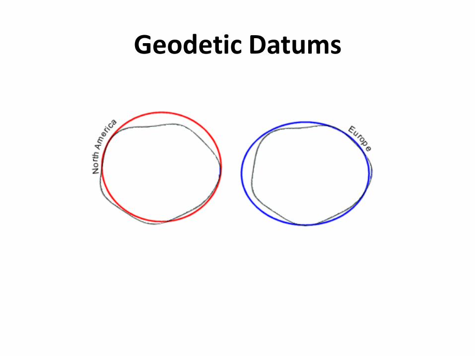
Geodetic Datums
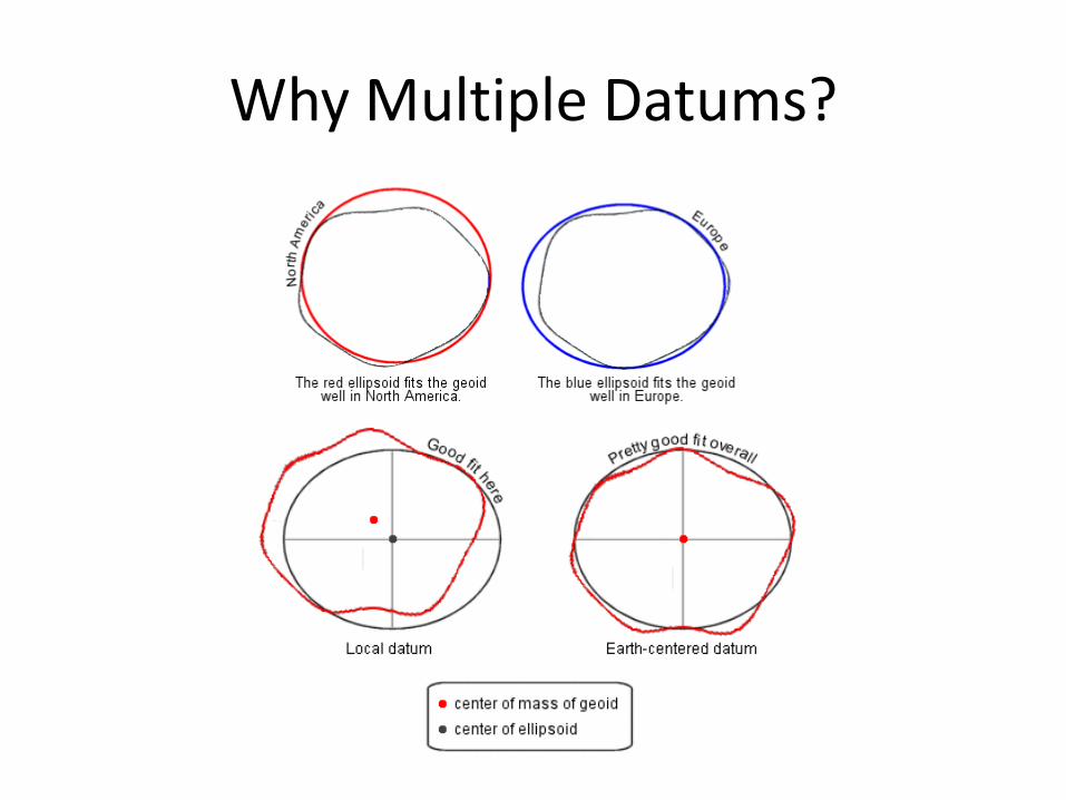
Why Multiple Datums?
Horizontal Reference Datums
• Datums are the collection of very accurate control points (points of known accuracy) surveyors use to geo-reference all other map data
• Surveyors determine the precise latitude and longitude of horizontal control points spread across the landscape
Horizontal Reference Datums
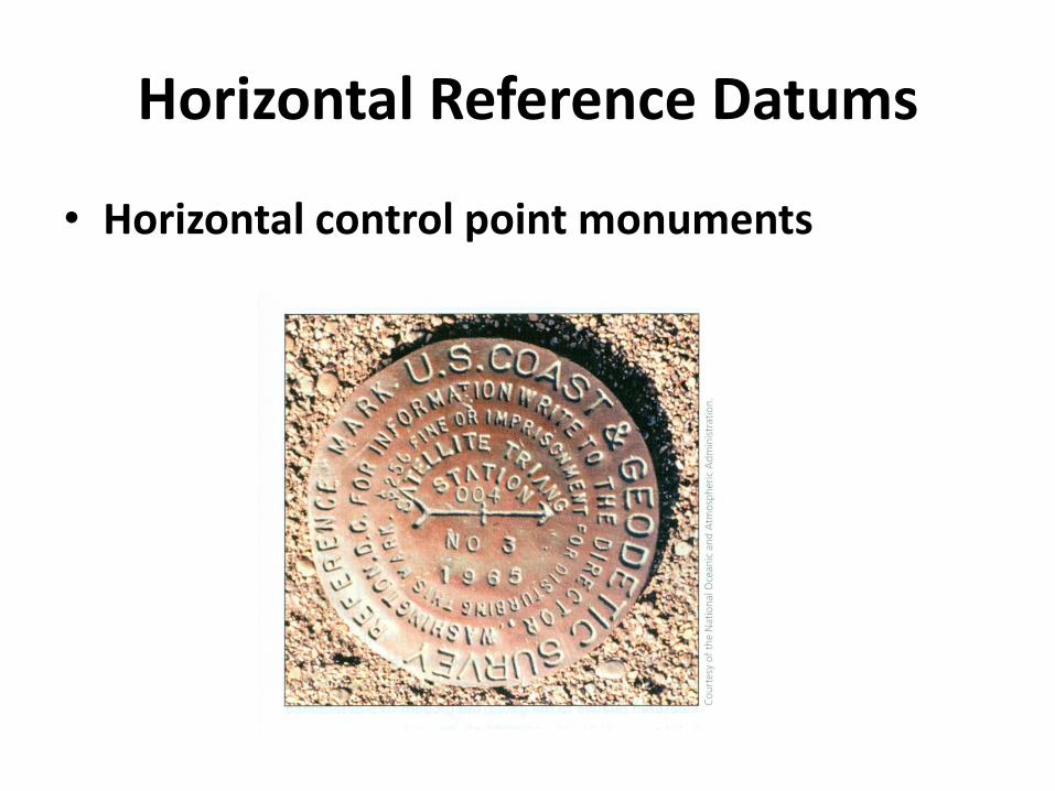
• Horizontal control point monuments
Horizontal control point monuments
• From the 1920s to the early 1980s,these control points were surveyed relative to the surface of the Clarke 1866 ellipsoid, together forming what is called the North American Datum of 1927 (NAD 27)
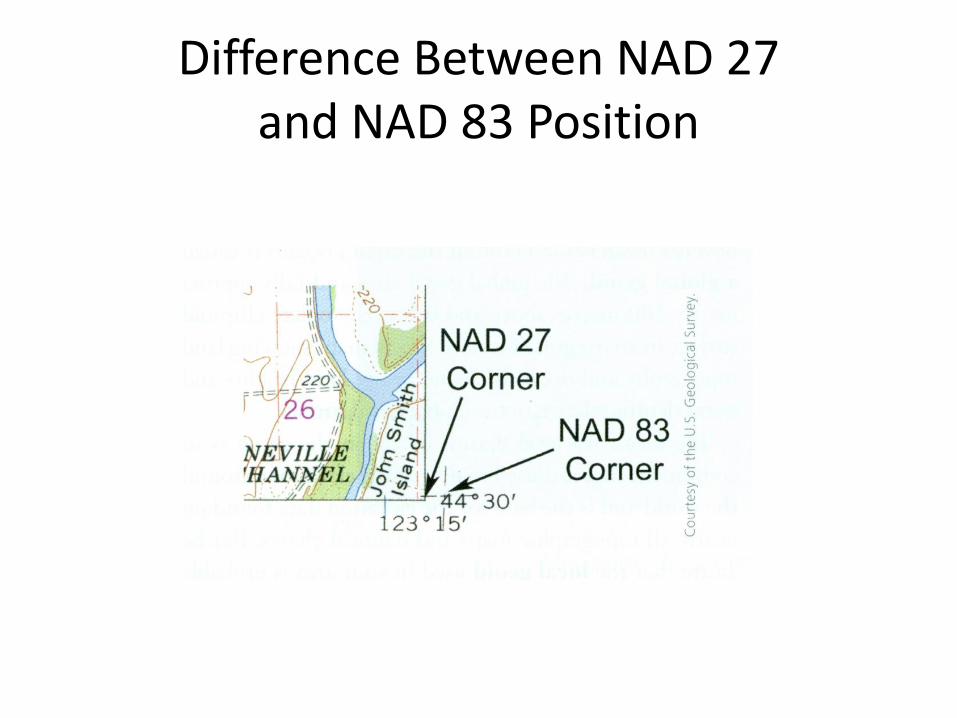
Difference Between NAD 27 and NAD 83 Position
Changes in Datums
• By the early 1980s, better knowledge of the earth’s shape and size and far better surveying methods let to the creation of a new horizontal reference datum, the North American Datum of 1983 (NAD 83)
Changes in Datums
• The latitudes and longitudes of all of these points were determined relative to the Geodetic Reference System of 1980 (GRS 80)ellipsoid, which is essentially identical to the WGS 84 ellipsoid
The Earth as a Geoid
• The earth’s surface is truly smooth when we compare the surface undulations to the 7,918 mile diameter of the earth
• The greatest relief variation is the approximately 12.3 mile difference between the summit of Mt. Everest (29,035 feet) and the deepest point in the Marianas Trench (36,192 feet)
The Earth as a Geoid
• The top of Mt. Everest is located at:
27o59’N, 86o56’E, 29,035 feet (8,852 meters)
Vertical Reference Datums
• The traditional datum used for land elevation is mean sea level (MSL)
• Surveyors define mean sea level as the average for all low and high tides at a particular starting location over a metoniccycle (the 19 year cycle of the lunar phases and days of the year)
Vertical Reference Datums
• A small circular monument was placed in the ground at each surveyed benchmark elevation point
• A benchmark is a permanent monument that establishes the exact elevation of a place
Vertical Reference Datums
• Later, surveyors could determine elevation by making gravity measurements at different locations on the landform and relating them to the strength of gravity at the point used to define MSL
• Gravity differences translate into elevation differences
Vertical Reference Datums
• Mean sea level is easy to determine along coastlines, but what about inland locations?
The Earth as a Geoid
Global Geoid
• The slightly undulating, nearly ellipsoidal surface that best fits mean sea level for all the earth’s surface is called a global geoid
• The global geoid rises and falls approximately 100 meters above and below the oblate ellipsoid surface in an irregular pattern
Global Geoid
• World maps showing land topography and ocean bathymetry use land heights and water depths relative to the global geoid surface
• Be aware that the local geoid used in your area is probably slightly above or below (usually within 2 meters) the global geoid elevations used on world maps
NGVD 29
• In the US you may see elevations relative to the National Geodetic Vertical Datum of 1929 (NGVD 29) on older topographic maps
• This datum was defined by the observed heights of mean sea level at 26 tide gauges, 21 in the US and 5 in Canada
North American Vertical Datum of 1988 (NAVD 88)
• Mean sea level for the continent was defined at one tidal station on the St. Lawrence River at Rimouski, Quebec, Canada
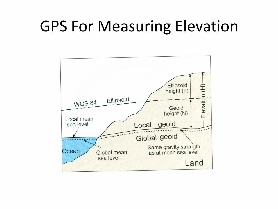
GPS For Measuring Elevation
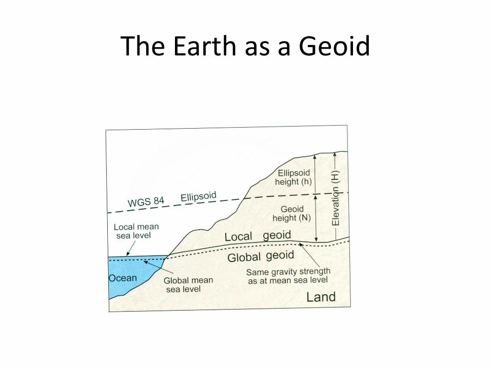
• GPS receivers calculate what is called the ellipsoidal height, the distance above or below the surface of the WGS 84 ellipsoid along a line from the surface to the center of the earth
GPS For Measuring Elevation
GPS For Measuring Elevation
• You must convert GPS ellipsoidal heightvalues to mean sea level datum elevations before you can use them with existing maps
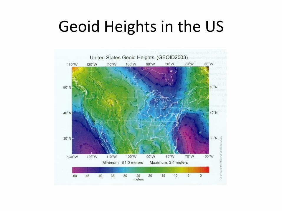
Geoid Heights in the US
Grid Coordinate Systems
• The latitude and longitude graticule has been used for over 2000 years as the worldwide locational reference system
• Geocentric latitude and longitude coordinates on a sphere or geodetic latitudes and longitudes on an oblate ellipsoid, still key to modern position finding, are not as well suited for making measurements of length, directionand area on the earth’s surface
Grid Coordinate Systems
• The advantage of the flat map projection surface is that we can locate something by using a two-axis coordinate reference system
• This coordinate system is the basis for the square grid of horizontal and vertical lines on a map
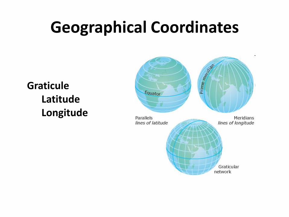
Geographical Coordinates
GraticuleLatitudeLongitude
Grid Coordinate Systems
• We call a plane-rectangular coordinate system based upon and mathematically placed on a map projection a grid coordinate system
• All geographic grid systems are based on Cartesian coordinates, invented in 1637 by the famous French philosopher and mathematician Rene Descartes
Cartesian Coordinates
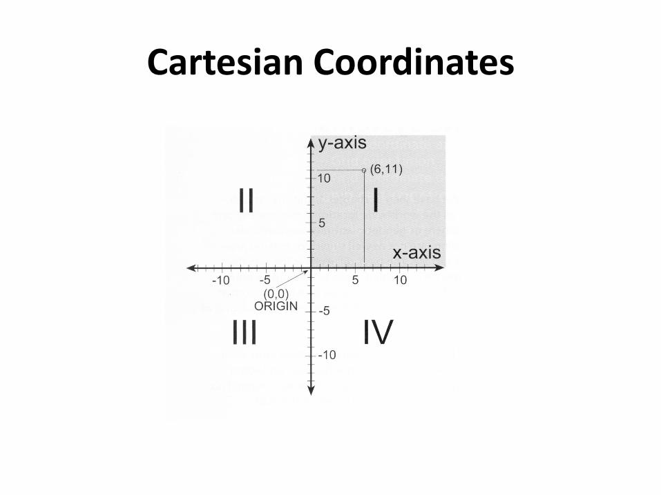
• If you superimpose a square grid on a map, with divisions on a horizontal x-axis and a vertical y-axis where the axes cross at the system’s origin, you have established the Cartesian Coordinate System
Cartesian Coordinates
Grid Coordinates
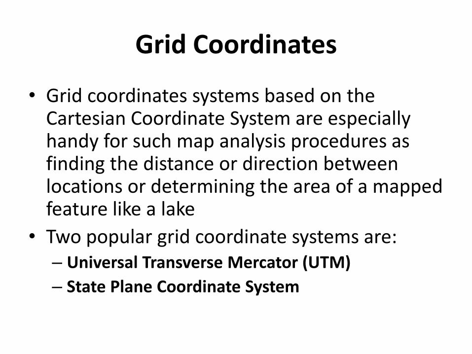
• Grid coordinates systems based on the Cartesian Coordinate System are especially handy for such map analysis procedures as finding the distance or direction between locations or determining the area of a mapped feature like a lake
• Two popular grid coordinate systems are:– Universal Transverse Mercator (UTM)
– State Plane Coordinate System
Universal Transverse Mercator System
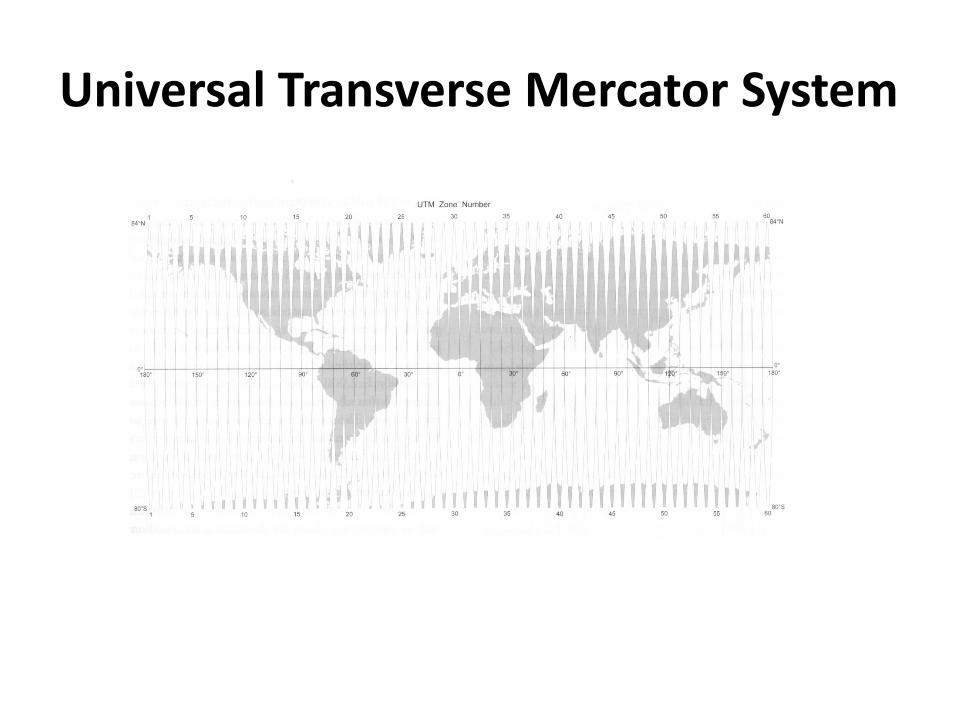
• The UTM grid extends around the world from 84oN to 80oS
• 60 north-south zones are used, each 6o
longitude
Universal Transverse Mercator System
Universal Transverse Mercator System
• Each zone has its own central meridian and uses a secant case transverse Mercator projection centered on the zone’s central meridian for each of the 60 zones
• Scale factors ranging from 0.9996 to 1.0004within each zone
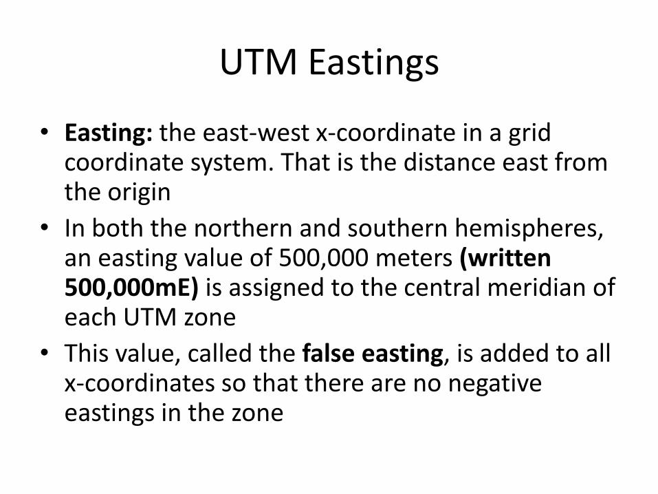
UTM Eastings
• Easting: the east-west x-coordinate in a grid coordinate system. That is the distance east from the origin
• In both the northern and southern hemispheres, an easting value of 500,000 meters (written 500,000mE) is assigned to the central meridian of each UTM zone
• This value, called the false easting, is added to all x-coordinates so that there are no negative eastings in the zone
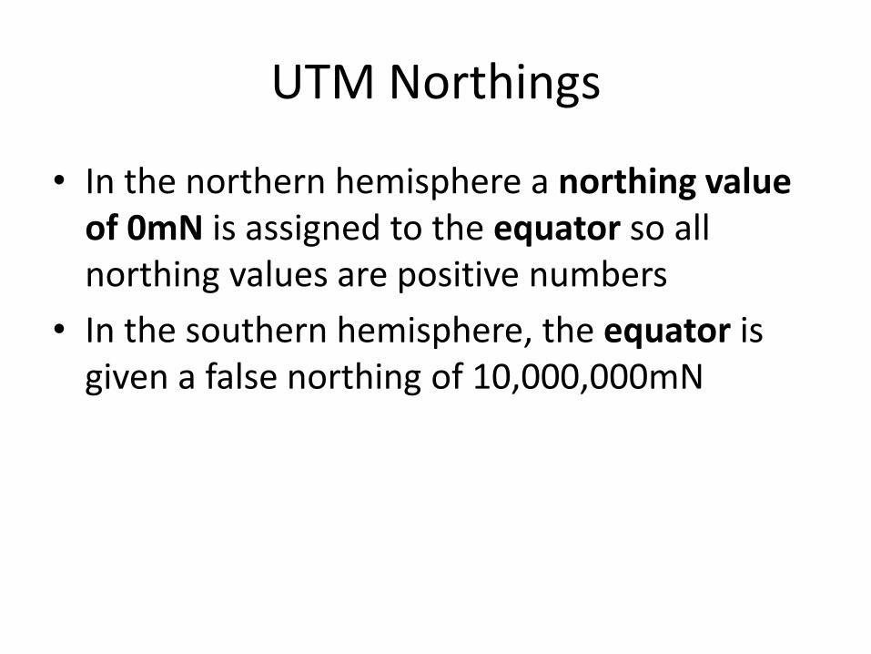
UTM Northings
• In the northern hemisphere a northing value of 0mN is assigned to the equator so all northing values are positive numbers
• In the southern hemisphere, the equator is given a false northing of 10,000,000mN
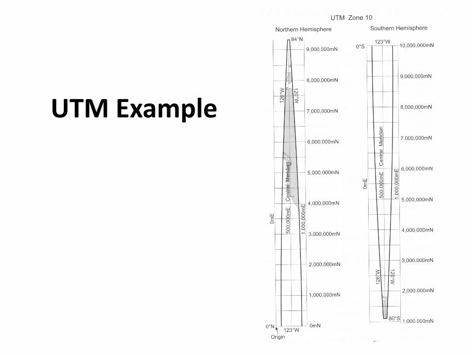
UTM Example
Another UTM Example
UTM Coordinates of the 68th St Entrance to the North Building
• 587390.92mE, 4513546.43mN, Zone 18 North
UTM
• All GPS vendors program the UTM specifications into their receivers
• Note that UTM coordinates will differ when different datums are used
Universal Polar Stereographic System
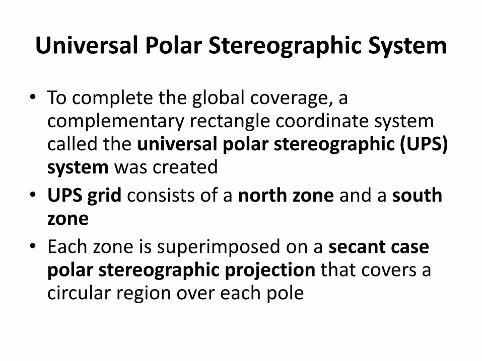
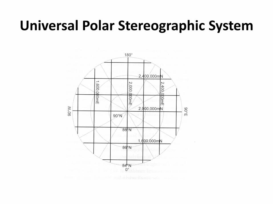
• To complete the global coverage, a complementary rectangle coordinate system called the universal polar stereographic (UPS) system was created
• UPS grid consists of a north zone and a south zone
• Each zone is superimposed on a secant case polar stereographic projection that covers a circular region over each pole
Universal Polar Stereographic System
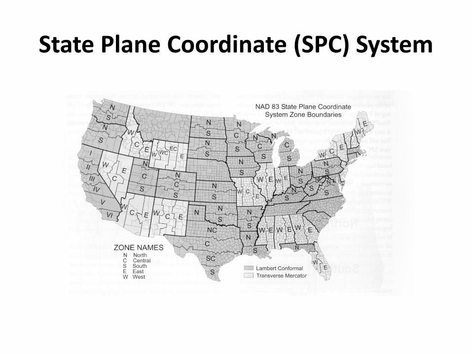
State Plane Coordinate (SPC) System
• The idea was to completely cover the US and its territories with grids laid over map projection surfaces so that the maximum scale distortion error would not exceed 1 part in 10,000
• The US was originally divided into 125 zones
• Each has its own projection surface based on the Clarke 1866 ellipsoid and NAD 27geodetic latitudes and longitudes
State Plane Coordinate (SPC) System
State Plane Coordinate (SPC) System
• Secant case Lambert conformal conic projections are used for states of predominantly east-west extent
• Secant case transverse Mercator projectionsare used for states of greater north-southextent
State Plane Coordinate (SPC) System
• Zone boundaries follow state and county boundaries because surveyors have to register land surveys in a particular county
• Each zone has its own central meridian that defines the vertical axis for the zone
• An origin is established to the west and south of the zone
State Plane Coordinate (SPC) System
• Usually 2,000,000 feet west of the central meridian for the Lambert conformal conic zones and
• 500,000 feet for the transverse Mercator zones
State Plane Coordinate (SPC) System
• For example the location of the state capitol dome in Madison Wisconsin is:
– 2,164,600 ft E, 392,280 ft N, Wisconsin, south zone
Other Grid Systems
• US state grids – combine UTM zones into a single state grid
• European grid coordinate systems
• British National Grid coordinate system
• Swiss coordinate system