early applications of prestressed concrete in the … sp-231—2 early applications of prestressed...
TRANSCRIPT

15
SP-231—2
Early Applications of PrestressedConcrete in the United Kingdom
by C. Burgoyne
Synopsis:Synopsis:Synopsis:Synopsis:Synopsis: The initial impetus to the application of prestressed concrete in the UnitedKingdom was heavily driven by the conditions imposed by the Second World War.Refugees from Germany, particularly Mautner and Abeles, brought skills andknowledge of tests carried out in France and Germany. The need to provide emergencystructures, both for military purposes and to meet civilian needs, together withshortages of many materials, especially steel, led to the construction of beams on ascale, and at a speed, which would not have taken place in more normal times. Thepaper covers developments in the UK from the outbreak of the war in 1939 up to theearly 1950s, when more normal times returned. This period of development is still notproperly documented because security conditions prevented the publication of fulldetails of the applications.
Keywords: history; prestressed concrete; United Kingdom

16 BurgoyneChris Burgoyne is Reader in Concrete Structures at the University of Cambridge. His
principal research interest is in the use of aramid fibres as prestressing tendons for
concrete structures, but his interest in the historical development of prestressed concrete
stems from working with the late Prof. Sir Alan Harris at Imperial College in London.
INTRODUCTION
Prestressed Concrete was not developed in Britain, but several early applications took
place there. The Second World War had a major effect since it significantly affected both
the need for structural elements and the supply of materials.
Freyssinet’s used jacking at the crown of arches at Rairéals-sur-Besbre (1911), Veurdre
(1912) and Boutiron (1913 – Figure 1) to overcome the effects of concrete shrinkage and
creep1
, and he conducted laboratory experiments which eventually led to his influential
patent in 19282
. Glanville’s more theoretical work on creep at the Building Research
Station in England was taking place at the same time3
, but it was undoubtedly
Freyssinet’s work that led directly to prestressed concrete. He recognised that high-
strength concrete and high steel pre-strains were needed to leave some prestress after
creep had taken place.
The first publication drawing the attention of British engineers to prestressed concrete
was a paper by Gueritte in 1936, read before the Institution of Structural Engineers; this
was a translation of a paper by Freyssinet, who attended the meeting4
. Gueritte had, as
early as 1931, read a paper before the British Section of the Société des Ingénieurs Civils
de France, describing the views of Freyssinet5
; this was only one year after Freyssinet
had extended his patent for the use of prestressed concrete. The 1931 paper was,
however, more concerned with the bridge at Plougastel, near Brest, and the novel
centring system used there. It refers to the properties of concrete lying somewhere
between those of a solid and a liquid (an implicit reference to viscoelasticity), but gives
few details. It also talks of the benefits of providing confining reinforcement to enhance
the strength of the section.
The company of L. G. Mouchel and Partners, who had built up a pre-eminent role in
reinforced concrete as holders of the U.K. licences, set up the Prestressed Concrete
Company as early as 1937. The company does not appear to have become fully active
until the arrival in the UK of Dr. Karl Mautner in the summer of 1939. Mautner had been
a director of Wayss & Freitag in the 1930s, and was also a professor at Aachen. He was
of Jewish descent, but despite holding the Iron Cross as a result of his distinguished
service in WWI, he was rounded up with other Jewish professionals and placed in
Buchenwald concentration camp in 1938. At that time, however, it was possible to buy
oneself out of the camps and with the help of the Mouchel Company in England, and
probably also of the British Secret Services, he came to England. He brought with him
details of Freyssinet’s work, with which, as licensee, Wayss and Freitag had been
actively involved6
.

Ned H. Burns Symposium 17Gueritte published two further papers in the early 1940s. The first
7
, in July 1940,
describes the mass-production of precast, pretensioned beams; it also describes the design
of emergency bridge beams and the design of a 3-span post-tensioned river bridge with a
main span of 48 m, the central 15 m of which were formed of a simply-supported span.
There was also a technical appendix written by Mautner. The second paper, published in
19418
, gave extensive details of a test carried out at Southall on a beam 8.8 m long
(Figure 2), and also described the test carried out about 5 years before, in Germany, on a
longer beam designed by Freyssinet and tested by Mautner. The various developments
sprang from this work.
In this paper locations are given using the Ordnance Survey Grid Coordinate system9
,
which consists of two letters and 6 numbers, sufficient to define any location to within
100m. These coordinates, when entered into UK-based web mapping systems10
, will
produce detailed maps of each location, at a variety of scales.
WAR-TIME CONSTRUCTION
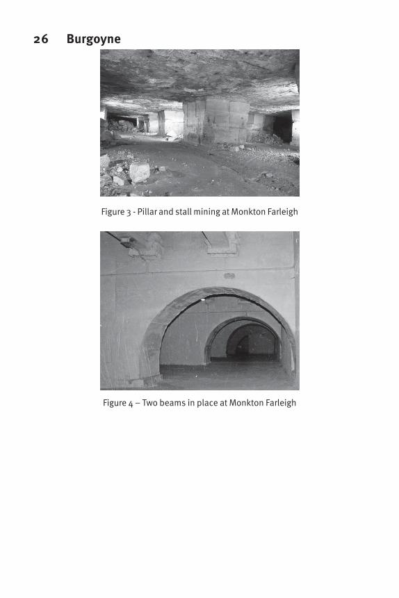
Monkton Farleigh Mine. The limestone mines at Monkton Farleigh in Wiltshire
(ST799656) had been worked in the 18th and 19th centuries to extract a seam of high
quality freestone that was used to construct the city of Bath. The seam was about 5 m
thick and typically 25 – 30 m below the surface. It had been excavated using the pillar
and stall method, leaving quite sizable columns of stone to support the overlying lower-
quality limestone that was not extracted (Figure 3). This mine, and others in the vicinity,
were used as bomb-proof bunkers to store ammunition and other ordnance before it was
required11
. They covered some 80 hectares and were capable of storing about 350,000
tonnes of bombs. Monkton Farleigh mine was connected to the main Great Western
Railway by means of a narrow-gauge railway tunnel and also by an aerial ropeway.
The original pillars left by the miners were irregular, and not suited to mechanical
handling, so it was decided to replace the pillars by regularly-spaced walls, 5 m apart, and
to use prestressed concrete beams at 1.5 m centres. Mr Allan of the Ministry of Public
Buildings and Works, and Lt-Col Withers of the Royal Engineers, decided in 1939 to
investigate the use of prestressed concrete for these beams, which were designed in
consultation with Mautner and successfully tested12
. They were designed for a central
point load of 81.5 kN applied at the centre of the span, and were clearly intended to
restrain loose blocks of stone falling from the roof rather than supporting the whole of the
overburden, so they do not appear to have been loaded initially. Access to the mine was
by inclined adits. Figure 4, which was not taken specifically to include the beams, shows
two such girders. They were supported at their ends by steel rods hanging from brackets
let into the walls; in the photograph these have been sprayed with concrete, presumably
as corrosion or fire protection.
The scheme went ahead, with the intention that every third wall would be built, after
which the intervening pillars would be removed and the intermediate walls completed.
However, the demolition of the pillars took place much more quickly than the building of
the walls, with the result that large areas of the ceiling were left unsupported and some of

18 Burgoynethe walls that had been completed were overloaded
13
. A collapse occurred and the whole
rebuilding scheme was cancelled, with the result that only a limited number of
prestressed beams were installed. Nevertheless, this appears to be the first use of
prestressed concrete in the UK.
The beams are described in Gueritte’s paper in 19407
; although he does not mention the
mine by name it is clear that these are the beams to which he refers. The paper also gives
details of the anchorage blocks used in the stressing beds (Figure 5). With plans to
fabricate such a large number of beams in a very short period of time, long-line
fabrication was adopted. Nine parallel prestressing beds were made, 151 m long, in each
of which 28 beams could be produced at the same time. The beams were complex in
shape; the drawings show them with rectangular cross-section at the ends but I-beam
section in the middle, with a web whose thickness varied along the length. 282 such
forms would have been required if all beds were in use simultaneously. Shear links were
provided and individual link spacings were specified, which today would be regarded as
impractical, although it shows the over-riding importance attached to the optimisation of
the steel. The tendons were stressed to about 1140 MPa so extensions of nearly a metre
had to be accommodated at the jacking point. This was done by stressing pairs of wires
using a yoke, with packing being installed once the desired extension had been reached.
Once the concrete had cured sufficiently, the jacks were reinstalled, the packing removed,
and the prestress released. If all 3000 beams had been built, each mould would have been
used 12 times, and allowing for transfer of prestress at an age of seven days, with another
week in between for setting up the reinforcement and concreting, it would have taken
some 6 months of flat-out operation to complete the order.
There was relatively little to see on the surface, with a view to avoiding the attentions of
the Luftwaffe, but the site was bombed in August 1940; it is thought that the bombers
mistook the stressing bed for the (much longer) runway on a nearby airfield which was
their intended target. Figure 6 was taken by the RAF to check the site camouflage; it was
deemed to be unsatisfactory.
The mine is no longer used to store ammunition, but some parts have been taken over for
commercial secure storage of documents and computer media. As a result, large parts are
inaccessible and none is open to the public. Some of the beams are still in place,
although their present condition is unknown. Grote gives a sketch of the present layout
of the beams6
.
Railway Ties (Sleepers in UK parlance). Prestressed concrete railway sleepers were
introduced in 194214
. There had previously been experiments with reinforced concrete
sleepers, as early as 1917 in Ireland, with others on the LNER main line in 1928, but
these were generally unsatisfactory as the reinforced concrete crumbled when subject to
frequent heavy loads15
. Wartime difficulties in obtaining suitable hardwood for the
traditional timber sleepers led to further experiments in 1941 with reinforced concrete16
,
and some were put onto a branch line near Derby. The tests were inconclusive, so the
next year 100 of the sleepers were placed on the main LMS line near Watford; they
survived for 10 days. At the same time, development work was under way on prestressed

Ned H. Burns Symposium 19concrete sleepers, designed by Mautner for production on an experimental long-line
stressing bed at the Royal Signals Research Establishment (RSRE) at Malvern. The first
of these sleepers was used in a trial in 1942 and they were so successful that all work
ceased on reinforced concrete apart from occasional use in sidings. A purpose-built
factory was constructed by Dowsett at Tallington in 1943 and continues in production to
this day (Figure 7)17
. It has been estimated that after 50 years of production there were
some 35 million prestressed, pretensioned, monoblock sleepers in use in the UK alone14
.
The sleepers are designed for point loads applied by the rail, to be resisted by upward
pressures from the ballast (Figure 8). If the ballast is in good condition, support is
concentrated under the rails, but after settlement the ground support can be much more
uniformly distributed. The sleepers are normally in hogging bending between the rails,
and sagging bending under the rails; the top profile is altered so that the tendons remain
straight but are in the appropriate position to resist the different moments. No other
reinforcement is provided in the sleepers apart from a fixing to attach the rails14
.
Emergency Bridge Beams. During the early part of WWII there was a considerable need
for bridge beams for emergency repair. Many of these beams were made of steel, but it is
known that a number of prestressed concrete beams were also made. It is not known how
many beams were made nor, to a large extent, is it known where they were used.
Gueritte7
describes standard beams designed for spans of 4.6 m, 6.1 m, 9.1 m, 12.2 m
and 15.2 m. The beams were to be used side-by-side, with timber decking. In some
cases, the beams were to be tied together transversely by prestressed rods, which also
served to attach the handrails (Figure 9). It is clear that savings in the amount of steel
required were one of the primary advantages seen for these beams; it is also clear that
these bridges were expected to be temporary and were seen as a means of restoring
communication in the event of bomb damage. One surprising aspect is the
preponderance of box beams in the smaller sizes; although they are more likely to be
stable when placed, without any need for a transverse tie, the internal shutter must have
been difficult to form and wasteful of resources.
In the discussion to a later paper8
, Chettoe describes the construction method, which is
very similar to that used for the Monkton Farleigh beams. He mentions three fabrication
yards, using beds between 180 m and 250 m long, each with three or four parallel lines,
but he does not give named locations. Presumably these did not include the facility at
Monkton Farleigh itself, but it is very likely that they were situated at other Government
research establishments, such as RSRE where the sleepers were made. It is clear that a
very large number of these beams were probably built, but there is no central record of
where most of them were used. A paper published in the Institution of Civil Engineers in
194318
refers to two bridges built with these beams; these were clearly intended as
permanent installations. Mention is also made of another that was planned.
Bridge over the LMS in Lancashire. This bridge was one of those described in the
1943 paper18
(Figure 10). It has now been removed, but was located at OS Grid reference
SJ595948, where the A49 road crosses the West Coast Main Line in Newton-le-Willows.
The bridge was unofficially known as the Bloodystone Bridge since nearby was a

20 Burgoynemonument to the murder by a returning crusader of his wife’s lover. The bridge was
unusual in that the beams were skew to both the road and railway; the girders available
from the emergency bridge stock had to fit onto the existing bridge abutments and were
not the correct length for the skew span (Figure 11). The bridge was assessed in the early
1990s and a 7 tonne weight limit applied; the original cast-iron parapet beam and the
reinforced concrete slab at the side were replaced in 1993. The prestressed girders were
replaced in 1997; one of the principal reasons for its removal was the lack of shear
reinforcement linking the beams to the top slab.
Bridge in North Yorkshire. The other bridge referred to in the 1943 paper is at
Sinderby, where the Great North Road, now the A1, crossed the Ripon to Northallerton
Railway18
(Figure 12). It is at OS Grid Reference SE335811. The road was dualled in
the 1950s by adding two further carriageways to the west of the existing road; the old
road over the bridge now forms a little-used private access and is not part of the public
highway. The railway line has closed, and the void beneath both bridges has been filled-
in with earth and concrete, but the bridge deck, including the prestressed beams, remains
in position (Figure 13). The degree of support provided by the in-filling must be
doubtful, and it certainly prevents both ventilation and inspection. According to
Thomas19
, this bridge may have succeeded the LMS bridge above since it is said to have
incorporated ties to stop the beams spreading, which had occurred on the other bridge.
Despite having similar spans and prestress to the bridge at Newton-le-Willows, and also
having no steel linking the beams to the slab, this bridge has never had a weight limit
imposed. The long-term future of the bridge is uncertain since the road is soon to be
upgraded to motorway standard and the bridge will cease to have any use.
POST-WAR CONSTRUCTION
After the end of World War II, Britain's economy was in a very poor state, with serious
shortages of materials. Indeed, food rationing became worse after the end of hostilities,
and as much production as possible was diverted for export to earn foreign currency. The
back-log of maintenance that had built up meant that there was a heavy demand for steel;
one of the principal drivers for the adoption of prestressed concrete was thus the
recognition that prestressed concrete structures typically needed only about 25% of the
amount of steel for the flexural reinforcement and a slightly reduced need for shear
reinforcement because of the axial prestress that was induced.
The stock of emergency beams was used to rebuild bridges. It is claimed that they were
so cheap that new construction was unable to compete. No central record exists of where
these beams were used, but four locations were mentioned in 1949 in a brief note “An
Exhibition of Prestressed Concrete”20
; Linford (Hampshire), Bury St Edmunds (Suffolk),
Tilemill (Berkshire) and Newport Fronbridge (Pembrokeshire). However, it is probable
that a very large number of these beams existed and they would have been too valuable
an asset simply to throw away. Detailed locations of these bridges, and any others made
with the same beam stock, together with photos and condition reports, are still sought.

Ned H. Burns Symposium 21Adam Viaduct (1946) near Wigan carries the LMS railway from Wigan to the South
West, over the River Douglas, at SD57105121
. It has four spans of about 8.8 m each,
with sixteen I-beams in each span22
(Figures 14 and 15). It was prestressed with the
Freyssinet system. The advantages were claimed to be the speed of erection and the fact
that ballasted track could be used; the heavier beams meant that the bridge was also less
susceptible to vibration. This bridge is still in use and has recently (1999) been listed by
English Heritage, a process that recognises its architectural or historical significance, and
gives some degree of protection.
Nunn's Bridge, at Fishtoft near Boston in Lincolnshire, was the first application of post-
tensioning in the UK, in 194823
. The bridge has five beams 21.3m long, 1.1m deep below
an integral top slab (Figure 16). Each beam has twelve Freyssinet 12-wire draped
tendons. The bridge replaced a three-span brick arch built by Rennie which was
temporarily retained to support the falsework. The bridge is still in use and shows no
sign of rust staining or deterioration of the concrete; the only maintenance undertaken
appears to be attention to the handrails. The bridge is located at TF367415.
Masonry Repair (1948). The first application of the Magnel system in the UK was to
the strengthening of a church tower at Silverdale near Newcastle-under-Lyme in
Staffordshire24
(Figures 17 and 18). The tower was suffering seriously from subsidence
caused by coal mining. The badly-cracked masonry was injected with grout to
consolidate the brickwork to form “beams” of appropriate shape. A channel was cut into
these beams to receive the tendons which were stressed against steel anchorage plates.
Subsequently, the chase was filled with concrete to protect the tendons. The intention
was that, if any further subsidence occurred, the internal beams would behave as if
simply supported and prevent any further cracking of the masonry.
Airport Taxiway (1949). A prestressed concrete taxiway was built at the London
Airport at Heathrow25, 26
. This was similar to a complete runway slab built by Freyssinet
at Orly; the slab was only prestressed transversely, but was made up of a series of 45°
triangles (Figure 19). Vertical rollers were inserted in the joints, so as the slab contracted
transversely it pushed against end abutments, thus inducing a longitudinal prestress as
well. This system neatly overcomes the friction that would arise if direct application of
the longitudinal prestress were attempted. The slab was 120' wide by 355' long. At about
the same time a prestressed concrete road was constructed at Crawley, but this was
prestressed longitudinally, which must have caused significant friction to develop
between the slab and the ground27
.
Prestressed concrete in buildings (1949). Two notable applications of prestressing to
buildings took place in 1949. The first was the fabrication of roof beams for the new
Heathcote Factory at Tiverton in Devon28
, while the second was a much larger
application to a new storage and distribution facility for H.M. Stationery Office at
Sighthill in Edinburgh. This was the forerunner of precast, prestressed building
construction29, 30
. The secondary roof beams were pretensioned in a factory, while the
main beams and the secondary beams for the floor were precast on site and post-
tensioned before lifting them into position. These beams used the Magnel system, and
some of the tendons were curved up at the ends. This building is regarded as significant

22 Burgoynesince it took the ideas of precasting and prestressing from the bridge community to the
building community.
Partially Prestressed Concrete. Paul Abeles was another refugee who came to England
just before WW2. He was a believer in what is now called partially prestressed concrete,
where additional untensioned reinforcement was included in the beam. The idea was to
increase the ultimate moment capacity in the beam, with the primary effect of the
prestressing being to reduce the crack widths but not to prevent their formation. He
published a paper31
espousing his views in 1940, which was severely criticised by
Mautner in the subsequent discussion. The first major application of his techniques is
believed to be the reconstruction of railway bridges for the electrification of the LNER
railway out of Liverpool Street Station in London. The bridges had to be raised to allow
clearance for the overhead wires, without needing to raise the road. These beams were
discussed in a paper in 195232
. His systems were openly criticised - there were many
who said that rather than combining the advantages of reinforced and prestressed
concrete it combined their disadvantages instead. That debate continues to this day!
Conflicting systems. In the years after WWII there were many conflicting prestressing
systems. The Freyssinet system, under the guidance of Mautner and later Alan Harris,
were already established in the UK and held valid patents, but immediately after the war
Prof Magnel of Ghent University was actively publicising his system, and Abeles was
proposing the use of partially prestressed concrete. Many other systems were developed;
some to avoid the patents held by the early protagonists, but others with genuine
improvements33
. It was during this period that today’s standard systems were developed
using 7-wire strands held by 3-piece wedges.
The history after 1950 is well-documented - Concrete, The Structural Engineer and the
Proceedings of the Inst. Civil Engineers all carry many papers relating to innovations or
landmark prestressed concrete structures, and there have been a number of papers and
reviews giving details of prestressed concrete over the next 50 years34,35,36,37,38,39
.
CONCLUSIONS
While it is clear that prestressed concrete would probably have become a successful
material anyway, the special circumstances that came together in the United Kingdom
between 1938 and 1950 led to the more rapid introduction of the technique. Refugees
from Germany brought skills and knowledge with them; pressures to produce a large
number of beams very quickly for wartime purposes, combined with shortages of
materials, especially steel which was needed for many other purposes, all contributed to
the rise of prestressed concrete. Only after the war did questions about patents and
commercial exploitation arise.
It is probably unsurprising that wartime security concerns meant that details of the use of
prestressed concrete were not published more widely, and other technical achievements
in the war, such as Radar, the Spitfire, codebreaking and more visible civil engineering
Ned H. Burns Symposium 23achievements, such as the Mulberry Harbours, have captured public attention. But the
more effective use of concrete by prestressing also played its small part.
ACKNOWLEDGEMENTS
Figures 3, 4 and 6 were provided by Nick McCamley; Figure 11 by St Helens Council;
Figures 14 and 15 by wiganworld.co.uk .
REFERENCES
1. Freyssinet, E., Birth of prestressing. Library Translation 59, Cement and
Concrete Association. Translated from French, published by Travaux, July-
August 1954.
2. Freyssinet, E. and Séailles, J., Procédé de fabrication de pieces en béton armé
(Method for the production of reinforced concrete elements), French patent
680547, 1928.
3. Glanville, W.H., Creep of Concrete under load, The Structural Engineer, 11/2,
54-73, 1933.
4. Gueritte, T.J., A revolution in the technique of the utilisation of concrete, The
Structural Engineer, 14, 242-262, May 1936.
5. Gueritte, T.J., A study of the views of Monsieur Freyssinet, The Structural
Engineer, 9, 217-227, 1931.
6. Grote, J. and Marrey, B., Freyssinet, Prestressing and Europe, Editions du
Linteau, 2000.
7. Gueritte, T.J., Recent developments of pre-stressed concrete construction with
resulting economy in the use of steel, (with a technical appendix by Mautner),
The Structural Engineer, 18, 626-642, July 1940.
8. Gueritte, T.J., Further data concerning prestressed concrete: Comparison
between calculated stresses and stresses registered during test. Procs Inst. Civ.
Engrs., 91-136, 1941.
9. www.gps.gov.uk/natgrid/introduction.asp
10. www.multimap.co.uk
11. McCamley, N., Secret Underground Cities, Pen and Sword Books, Barnsley,
1988.
12. Withers, H. H. C., letter in Royal Engineers Journal, 61, 198, June 1947.
13. Whitehouse J., letter to Director of Fortifications and Works, 14 May 1940
14. Taylor H.P.J., The railway sleeper: 50 years of pretensioned, prestressed
concrete, The Structural Engineer, 71, 281-295, August 1993.
15. Anon, Reinforced Concrete Sleepers, Concrete Constr. Engng, 35, 267-279,
June 1940
16. Anon, Prestressed Concrete Sleepers, Concrete Constr. Engng, 41, 168-170,
June 1946.
17. Barber R. S. V. and Lester D.R., The development and manufacture of pre-
stressed concrete units, Transaction of the Society of Engineers, 41-75, 1946.
18. Paul A.A., The use of pre-cast pre-stressed concrete beams in bridge deck
construction, Procs Inst.Civ. Engrs, 21, 19-30, Nov 1943.

24 Burgoyne19. Thomas, F.G. (ed.), Procs Conference on Prestressed Concrete Inst. Civil
Engineers, February 1949.
20. Anon, An Exhibition of Prestressed Concrete, Concrete Constr. Engng, 44, 129,
April 1949.
21. Anon, A Prestressed Concrete Railway Bridge near Wigan, Concrete Constr.
Engng, 42, 305-308, October 1947.
22. Anon, Manufacture of Prestressed Concrete bridge Girders, Concrete Constr.
Engng, 43, 353-355, Nov 1948
23. Anon. Reconstruction of Nunn's Bridge, Lincolnshire; a prestressed cast-in-situ
structure, Concrete Constr. Engng, 43, 239-244, August 1948
24. Anon, Prestressing applied to Strengthening a Church Tower in Staffordshire,
Concrete Constr. Engng, 43, 280-283, Sept. 1948.
25. Anon. Prestressed Concrete Roof Beams at Tiverton, Concrete Constr. Engng,
44, 50-52, Feb 1949.
26. Anon. Prestressed Concrete beams in a Building at Edinburgh, Concrete
Constr. Engng, 44, 353-356, Nov 1949.
27. Anon. Prestressed Concrete Warehouse at Edinburgh, Concrete Constr. Engng,
46, 92-93, 1951.
28. Anon, An Experimental Prestressed Concrete Slab at London Airport, Concrete
Constr. Engng, 44, 176-177, June 1949.
29. Anon, Prestressed Concrete Runway at London Airport, Concrete Constr.
Engng, 47, 36-39, Jan 1952.
30. Anon, Prestressed Concrete Road at Crawley, Concrete Constr. Engng, 46, 147-
149, May 1951.
31. Abeles P.W., Saving reinforcement by pre-stressing, Concrete Constr. Engng,
35, 328-333, July 1940, with discussion by Mautner in 36, 73, Feb 1941.
32. Abeles P.W., Partially Prestressed Concrete Construction, Built in the Eastern
Region of British Railways 1948-1952, Publication of IABSE, 12, 1-14, 1952.
33. Andrew, A.E. and Turner, F.H., Post tensioning systems for concrete in the UK:
1940-1985. CIRIA Report 106, 1985.
34. Walley F., Prestressed Concrete, Design and Construction, HMSO, London,
1953.
35. Walley F., The childhood of prestressing - an introduction, The Structural
Engineer, 62A, 5-9, Jan 1984.
36. Sriskandan K., Prestressed Concrete road bridges in Great Britain: a historical
survey, Procs Inst. Civ. Engrs, 86, 269-303, 1989.
37. Sutherland R.J.M., Humm D. and Chrimes M. (Eds), Historic Concrete -
background to appraisal, Thomas Telford, 2001. Largely based on a special
issue of the Proc Inst. Civil Engineers, Structures and Buildings, 116, 255-482,
1996.
38. Harris A.J., Freyssinet, the genius of prestressing, The Structural Engineer, June
1997.
39. Taylor H.P.J., The precast concrete bridge beam - the last 50 years, The
Structural Engineer, 76, 407-414, 1998.

Ned H. Burns Symposium 25
Figure 1 – Boutiron Bridge
Figure 2 - Southall beam test6
26 Burgoyne
Figure 3 - Pillar and stall mining at Monkton Farleigh
Figure 4 – Two beams in place at Monkton Farleigh

Ned H. Burns Symposium 27
Figure 5 - Anchorage block at Monkton Farleigh stressing bed5
Figure 6 - Aerial view of the prestressing bed at Monkton Farleigh (ST797658)

28 Burgoyne
Figure 7 - Original long-line prestressing beds for railway sleepers13.
Figure 8 - Sleeper design process13

Ned H. Burns Symposium 29
Figure 9 - Emergency bridge cross sections (Redrawn from Reference 7)
Figure 10 - Plan of Bloodystone Bridge17
Figure 11 - Underside of Bloodystone Bridge showing cast-iron edge beam and taperingreinforced concrete side slab.

30 Burgoyne
Figure 12 - Cross section of Sinderby Bridge17
Figure 13 - The only exposed part of the prestressed beams at Sinderby (below parapet)
Figure 14 - Adam Viaduct, Wigan

Ned H. Burns Symposium 31
Figure 15 - Underside of girders at Adam Viaduct
Figure 16 - Nunn’s Bridge, Fishtoft
Figure 17 - Long section through church wall24

32 Burgoyne
Figure 18 - Plan of Silverdale church tower showing strengthened areas(Redrawn from Reference 24)
Figure 19 - Heathrow Airport Taxiway (Redrawn from Reference 28)