e6580757€¦ · e6580757 read first safety i precautions introduction contents connecting...
TRANSCRIPT

II
12345678910111213141516
E6580757
Read first
ISafety precautions
Introduction
Contents
Connecting equipment
Operations
Basic VF-S9 operations
Basic parameters
Extended parameters
Applied operation
Monitoring the operation status
Taking measures to satisfy the CE/UL directive
Peripheral devices
Table of parameters and data
Specifications
Before making a service call - Trip information and remedies
Inspection and maintenance
Warranty
Disposal of the inverter
NOTICE1. Make sure that this instruction manual is delivered to the
end user of the inverter unit.2. Read this manual before installing or operating the inverter
unit, and store it in a safe place for reference.
Instruction Manual
The new generation
Compact inverter
TOSVERT VF-S9
1-phase 200V class 0.2 2.2kW3-phase 200V class 0.2 15kW3-phase 400V class 0.75 15kW
TOSHIBA INDUSTRIAL PRODUCTS MANUFACTURING CORPORATION
2000 Ver. 101

E6580757
i
Contents
I Safety precautions.........................................................................................................................................................1
II Introduction....................................................................................................................................................................7
1. Read first .......................................................................................................................................................................A-11.1 Check product purchase....................................................................................................................................A-11.2 Contents of the product code.............................................................................................................................A-21.3 Names and functions.........................................................................................................................................A-31.4 Notes on the application ....................................................................................................................................A-10
2. Connection equipment...................................................................................................................................................B-12.1 Cautions on wiring .............................................................................................................................................B-12.2 Standard connections........................................................................................................................................B-32.3 Description of terminals .....................................................................................................................................B-6
3. Operations .....................................................................................................................................................................C-13.1 How to operate the VF-S9 .................................................................................................................................C-23.2 Simplified Operation of the VF-S9 .....................................................................................................................C-6
4. Basic VF-S9 operations .................................................................................................................................................D-14.1 How to set parameters.......................................................................................................................................D-2
5. Basic parameters...........................................................................................................................................................E-15.1 Setting acceleration/deceleration time ...............................................................................................................E-15.2 Increasing starting torque ..................................................................................................................................E-35.3 Setting environmental protection .......................................................................................................................E-55.4 Setting parameters by operating method...........................................................................................................E-55.5 Selection of operation mode ..............................................................................................................................E-75.6 Meter setting and adjustment.............................................................................................................................E-85.7 Standard default setting.....................................................................................................................................E-105.8 Selecting forward and reverse runs (operation panel only)................................................................................E-115.9 Maximum frequency ..........................................................................................................................................E-125.10 Upper limit and lower limit frequencies ..............................................................................................................E-125.11 Base frequency..................................................................................................................................................E-135.12 Selecting control mode ......................................................................................................................................E-145.13 Manual torque boost-increasing torque at low speeds ......................................................................................E-18

E6580757
ii
5.14 Setting the electronic thermal.............................................................................................................................E-185.15 Preset-speed operation (speed in 15 steps) ......................................................................................................E-22
6. Extended parameters.....................................................................................................................................................F-16.1 Input/output parameters .....................................................................................................................................F-16.2 Input signal selection..........................................................................................................................................F-46.3 Terminal function selection.................................................................................................................................F-66.4 Basic parameters 2 ............................................................................................................................................F-106.5 Frequency priority selection ...............................................................................................................................F-116.6 Operation frequency...........................................................................................................................................F-176.7 DC braking .........................................................................................................................................................F-186.8 Jog run mode .....................................................................................................................................................F-196.9 Jump frequency-jumping resonant frequencies .................................................................................................F-216.10 Preset-speed operation frequency 8 to 15 .........................................................................................................F-226.11 PWM carrier frequency ......................................................................................................................................F-226.12 Trip-less intensification.......................................................................................................................................F-236.13 Setting motor constants .....................................................................................................................................F-366.14 Acceleration/deceleration patterns and acceleration/deceleration 2 ..................................................................F-396.15 Protection functions............................................................................................................................................F-426.16 Operation panel parameter ................................................................................................................................F-506.17 Communication function (Common serial) .........................................................................................................F-54
7. Applied operation ...........................................................................................................................................................G-17.1 Setting the operation frequency .........................................................................................................................G-17.2 Setting the operation mode ................................................................................................................................G-5
8. Monitoring the operation status......................................................................................................................................H-18.1 Status monitor mode ..........................................................................................................................................H-18.2 Display of trip information...................................................................................................................................H-3
9. Taking measures to satisfy the CE/UL directive .............................................................................................................I-19.1 How to cope with the CE directive .....................................................................................................................I-1
10. Peripheral devices..........................................................................................................................................................J-110.1 Selection of wiring materials and devices ..........................................................................................................J-110.2 Installation of a magnetic contactor....................................................................................................................J-310.3 Installation of an overload relay .........................................................................................................................J-410.4 Optional external devices...................................................................................................................................J-4

E6580757
iii
11. Table of parameters and data ........................................................................................................................................K-111.1 User parameters................................................................................................................................................K-111.2 Basic parameters...............................................................................................................................................K-111.3 Extended parameters ........................................................................................................................................K-2
12. Specifications ................................................................................................................................................................L-112.1 Models and their standard specifications...........................................................................................................L-112.2 Outside dimensions and mass...........................................................................................................................L-3
13. Before making a service call-Trip information and remedies .........................................................................................M-113.1 Trip causes/warnings and remedies ..................................................................................................................M-113.2 Restoring the inverter from a trip .......................................................................................................................M-513.3 If the motor does not run while no trip message is displayed….........................................................................M-613.4 How to determine the causes of other problems................................................................................................M-7
14. Inspection and maintenance..........................................................................................................................................N-114.1 Regular inspection.............................................................................................................................................N-114.2 Periodical inspection..........................................................................................................................................N-214.3 Making a call for servicing .................................................................................................................................N-414.4 Keeping the inverter in storage..........................................................................................................................N-4
15. Warranty ........................................................................................................................................................................O-1
16. Disposal of the inverter ..................................................................................................................................................P-1

E6580757
1
II. Safety precautionsThe items described in these instructions and on the inverter itself are very important so that you can use theinverter safely prevent injury to yourself and other people around you as well as prevent damage to property inthe area. Thoroughly familiarize yourself with the symbols and indications shown below and then continue to readthe manual. Make sure that you observe all warnings given.
Explanation of markingsMarking Meaning of marking
Danger Indicates that errors in operation may lead to death or serious injury.
Warning Indicates that errors in operation may lead to injury (*1) to people or that these errors maycause damage to physical property. (*2)
(*1) Such things as injury, burns or shock that will not require hospitalization or long periods of outpatient treat-ment.
(*2) Physical property damage refers to wide-ranging damage to assets and materials.
Meanings of symbolsSymbol Meaning of Symbol
Indicates prohibition (Don't do it).What is prohibited will be described in or near the symbol in either text or picture form.
Indicates something mandatory (must be done).What is mandatory will be described in or near the symbol in either text or picture form.
Indicates danger.What is dangerous will be described in or near the symbol in either text or picture form.
Indicates warning.What the warning should be applied to will be described in or near the symbol in either text or picture form.
Limits in purposeThis inverter is used for controlling speeds of three-phase induction motors in general industrial use.
Safety precautionsThe inverter cannot be used in any device that would present danger to the human body or from whichmalfunction or error in operation would present a direct threat to human life (nuclear power control de-vice, aviation and space flight control device, traffic device, life support or operation system, safety de-vice, etc.). If the inverter is to be used for any special purpose, first get in touch with the people incharge of sales.This product was manufactured under the strictest quality controls but if it is to be used in criticalequipment, for example, equipment in which errors in malfunctioning signal output system would causea major accident, safety devices must be installed on the equipment.Do not use the inverter for loads other than those of properly applied three-phase induction motors ingeneral industrial use. (Use in other than properly applied three-phase induction motors may cause anaccident.)
E6580757
2
I General operation
Danger See item
Disassemblyprohibited
• Never disassemble, modify or repair. This can result in electric shock, fire and injury. Forrepairs, call your sales agency.
2.
Prohibited
• Never remove the front cover when power is on or open door if enclosed in a cabinet. Theunit contains many high voltage parts and contact with them will result in electric shock.
• Don't stick your fingers into openings such as cable wiring hole and cooling fan covers.This can result in electric shock or other injury.
• Don't place or insert any kind of object into the inverter (electrical wire cuttings, rods,wires). This can result in electric shock or fire.
• Do not allow water or any other fluid to come in contact with the inverter. This can result inelectric shock or fire.
2.1
2
2.
2.
Mandatory
• Turn power on only after attaching the front cover or closing door if enclosed in a cabinet.If power is turned on without the front cover attached or closing door if enclosed in a cabi-net. This can result in electric shock or other injury.
• If the inverter begins to emit smoke or an unusual odor, or unusual sounds, immediatelyturn power off.If the equipment is continued in operation in such a state, the result may be fire. Call yourlocal sales agency for repairs.
• Always turn power off if the inverter is not used for long periods of time since there is apossibility of malfunction caused by leaks, dust and other material.If power is left on with the inverter in that state, it may result in fire.
2.1
3.
3.
Warning See item
Prohibitedcontact
• Do not touch heat radiating fins or discharge resistors. These device are hot, and you'llget burned if you touch them.
3.
Prohibited
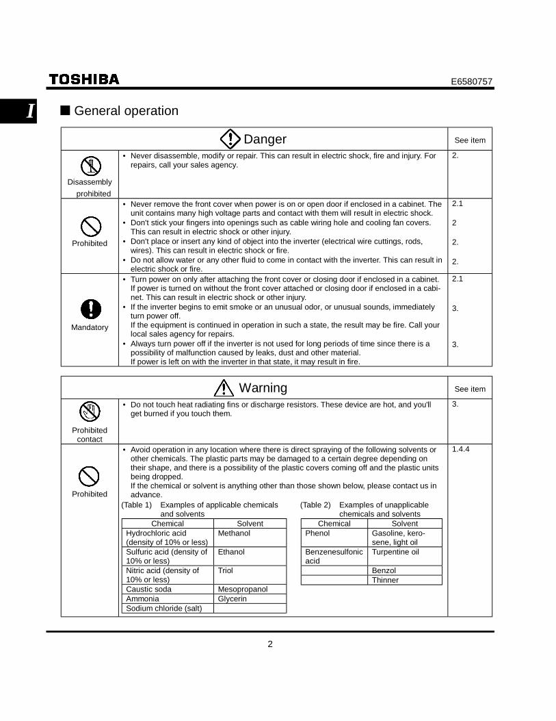
• Avoid operation in any location where there is direct spraying of the following solvents orother chemicals. The plastic parts may be damaged to a certain degree depending ontheir shape, and there is a possibility of the plastic covers coming off and the plastic unitsbeing dropped.If the chemical or solvent is anything other than those shown below, please contact us inadvance.
1.4.4
(Table 1) Examples of applicable chemicalsand solvents
Chemical SolventHydrochloric acid(density of 10% or less)
Methanol
Sulfuric acid (density of10% or less)
Ethanol
Nitric acid (density of10% or less)
Triol
Caustic soda MesopropanolAmmonia GlycerinSodium chloride (salt)
(Table 2) Examples of unapplicablechemicals and solvents
Chemical SolventPhenol Gasoline, kero-
sene, light oilBenzenesulfonicacid
Turpentine oil
BenzolThinner

E6580757
3
I Transportation À Installation
Danger See item
Prohibited
• Do not install or operate the inverter if it is damaged or any component is missing.This can result in electric shock or fire. Please consult your local sales agency for repairs.
• Do not place any inflammable objects nearby.If a flame is emitted due to malfunction, it may result in a fire.
• Do not install in any location where the inverter could come into contact with water orother fluids.This can result in electric shock or fire.
1.4.4
1.4.4
2.
Mandatory
• Must be used in the environmental conditions prescribed in the instruction manual.Use under any other conditions may result in malfunction.
• Must be installed in non-inflammables such as metals.The rear panel gets very hot. If installation is in an inflammable object, this can result infire.
• Do not operate with the front panel cover removed. This can result in electric shock.• An emergency stop device must be installed that fits with system specifications (e.g. shut
off input power then engage mechanical brake).Operation cannot be stopped immediately by the inverter alone, thus risking an accidentor injury.
• All options used must be those specified by Toshiba. The use of any other option may re-sult in an accident.
1.4.4
1.4.4
1.4.4
1.4.4
1.4.4
Warning See item
Prohibited
• When transporting or carrying, do not hold by the front panel covers.The covers may come off and the unit will drop out resulting in injury.
• Do not install in any area where the unit would be subject to large amounts of vibration.That could result in the unit falling, resulting in injury.
2.
1.4.4
Mandatory
• The main unit must be installed on a base that can bear the unit's weight.If the unit is installed on a base that cannot withstand that weight, the unit may fall result-ing in injury.
• If braking is necessary (to hold motor shaft), install a mechanical brake. The brake on theinverter will not function as a mechanical hold, and if used for that purpose, injury may re-sult.
1.4.4
1.4.4
Wiring
Danger See item
Prohibited
• Do not connect input power to the output (motor side) terminals (U/T1,V/T2,W/T3). Thatwill destroy the inverter and may result in fire.
• Do not connect resistors to the DC terminals (across PA-PC or PO-PC). That may cause afire.Connect resistors as directed by the instructions for "Installing separate braking resistors."
• Within ten minutes after turning off input power, do not touch wires of devices (MCCB)connected to the input side of the inverter .That could result in electric shock.
2.2
2.2
2.2

E6580757
4
I Danger See item
Mandatory
• Electrical construction work must be done by a qualified expert.Connection of input power by someone who does not have that expert knowledge may re-sult in fire or electric shock.
• Connect output terminals (motor side) correctly.If the phase sequence is incorrect, the motor will operate in reverse and that may result ininjury.
• Wiring must be done after installation.If wiring is done prior to installation that may result in injury or electric shock.
• The following steps must be performed before wiring.(1) Turn off all input power.(2) Wait at least ten minutes and check to make sure that the charge lamp is no longer lit.(3) Use a tester that can measure DC voltage (800VDC or more), and check to make sure
that the voltage to the DC main circuits (across PA-PC) is 45V or less.If these steps are not properly performed, the wiring will cause electric shock.
• Tighten the screws on the terminal board to specified torque.If the screws are not tightened to the specified torque, it may lead to fire.
• Check to make sure that the input power voltage is +10%, -15% of the rated power volt-age written on the rating label (±10% when the load is 100% in continuous operation)If the input power voltage is not +10%, -15% of the rated power voltage (±10% when theload is 100% in continuous operation) this may result in fire.
2.1
2.1
2.1
2.1
2.1
1.4.4
Be Grounded
• Ground must be connected securely.If the ground is not securely connected, it could lead to electric shock or fire when a mal-function or current leak occurs.
2.12.2
Warning See item
Prohibited
• Do not attach equipment (such as noise filters or surge absorbers) that have built-in ca-pacitors to the output (motor side) terminals.That could result in a fire.
2.1
Operations
Danger See item
Prohibited
• Do not touch inverter terminals when electrical power is going to the inverter even if themotor is stopped.Touching the inverter terminals while power is connected to it may result in electric shock.
• Do not touch switches when the hands are wet and do not try to clean the inverter with adamp cloth. Such practices may result in electric shock.
• Do not go near the motor in alarm-stop status when the retry function is selected.The motor may suddenly restart and that could result in injury.Take measures for safety, e.g. attaching a cover to the motor, against accidents when themotor unexpectedly restarts..
3.
3.
3.
Mandatory
• Turn input power on after attaching the front cover.When storing inside the cabinet and using with the front cover removed, always close thecabinet doors first and then turn power on. If the power is turned on with the front cover orthe cabinet doors open, it may result in electric shock.
• Make sure that operation signals are off before resetting the inverter after malfunction.If the inverter is reset before turning off the operating signal, the motor may restart sud-denly causing injury.
3.
3.

E6580757
5
I Warning See item
Prohibited
• Observe all permissible operating ranges of motors and mechanical equipment. (Refer tothe motor's instruction manual.) Not observing these ranges may result in injury.
3.
When sequence for restart after a momentary power failure is selected(inverter)
Warning See item
Mandatory
• Stand clear of motors and mechanical equipmentIf the motor stops due to a momentary power failure, the equipment will start suddenly af-ter power recovers. This could result in unexpected injury.
• Attach warnings about sudden restart after a momentary power failure on inverters, mo-tors and equipment for prevention of accidents in advance.
6.12.1
6.12.1
When retry function is selected (inverter)
Warning See item
Mandatory
• Stand clear of motors and equipment.If the motor and equipment stop when the alarm is given, selection of the retry function willrestart them suddenly after the specified time has elapsed. This could result in unex-pected injury.
• Attach warnings about sudden restart in retry function on inverters, motors and equipmentfor prevention of accidents in advance.
6.12.3
6.12.3
Maintenance and inspection
Danger See item
Prohibited
• Do not replace parts.This could be a cause of electric shock, fire and bodily injury. To replace parts, call the lo-cal sales agency.
14.2
Mandatory
• The equipment must be inspected every day.If the equipment is not inspected and maintained, errors and malfunctions may not be dis-covered and that could result in accidents.
• Before inspection, perform the following steps.(1) Turn off all input power to the inverter.(2) Wait for at least ten minutes and check to make sure that the charge lamp is no longer
lit.(3) Use a tester that can measure DC voltages (800VDC or more), and check to make
sure that the voltage to the DC main circuits (across PA-PC) is 45V or less.If inspection is performed without performing these steps first, it could lead to electricshock.
14.
14.

E6580757
6
I Disposal
Warning
Mandatory
• If you throw away the inverter, have it done by a specialist in industry waste disposal*.If you throw away the inverter by yourself, this can result in explosion of capacitor or produce noxiousgases, resulting in injury.
(*) Persons who specialize in the processing of waste and known as "industrial waste product collectorsand transporters" or "industrial waste disposal persons."If the collection, transport and disposal of industrial waste is done by someone who is not licensed forthat job, it is a punishable violation of the law. (laws in regard to cleaning and processing of wastematerials)
Attach warning labels
Shown here are examples of warning labels to prevent, in advance, accidents in relation to inverters, motors and otherequipment.If the inverter has been programmed for auto-restart function after momentary power failure or retry function, placewarning labels in a place where they can be easily seen and read.
If the inverter has been programmed for restart se-quence of momentary power failure, place warninglabels in a place where they can be easily seen andread.(Example of warning label)
If the retry function has been selected, place warninglabels in a location where they can be easily seen andread.
(Example of warning label)
Warning(Functions pro-grammed for restart)
Do not go near motors and equipment. Motorsand equipment that have stopped temporarily af-ter momentary power failure will restart suddenlyafter recovery.
Warning (Functions pro-grammed for retry)
Do not go near motors and equipment. Motorsand equipment that have stopped temporarily af-ter an alarm will restart suddenly after the speci-fied time has elapsed.

E6580757
7
IIII. Introduction
Thank you for your purchase of the Toshiba "TOSVERT VF-S9" industrial inverterThis is the Ver.101 CPU version inverter.Please be informed that this version will be frequently upgraded.
Features1. Built-in noise filter
1) All models in both the 200V and 400V series have a noise filter inside.2) These models conform to European CE markings and United States UL standards.3) Reduces space requirements and cuts down on time and labor needed in wiring.
2. Simple operation1) Automatic functions (torque boost acceleration/deceleration time, function programming, environment
programming)Just by wiring the motor to the power supply allows instant operation without the need to program pa-rameters.
2) Switches and potentiometer dial on the front panel allow immediate and easy operation.
3. Superior basic performance1) Torque from low frequency to 150% and higher2) Smooth operation : Reduced rotation ripple through the use of Toshiba's unique dead-band compen-
sation.3) Built-in current surge suppression circuit : Can be safely connected even if power load is low.4) Maximum 400Hz high frequency output : Optimum for use with high speed motors such as those in
lumber machinery and milling machines.5) Maximum carrier frequency: 16.5kHz quiet operation
Toshiba's unique PWM control reduces noise at low carrier.
4. Globally compatible1) Compatible with 240V and 500V power supplies2) Conforms to CE marking and with UL, CUL and C-Tick.3) Sink/source switching of control input/output.
5. Options allow use with a wide variety of applications• Communication functions (RS485/RS232C)• Extension panel/Parameter writer• DIN rail kit (For 200V class 0.2 to 0.75 kW)• Foot-mounted type noise reduction filter (EMC directive: For class A and class B)• Other options are common to all models

E6580757
A-1
1
1. Read first1.1 Check product purchase
Before using the product you have purchased, check to make sure that it is exactly what you ordered.
Warning
Mandatory
Use an inverter that conforms to the specifications of power supply and three-phase induction motor be-ing used. If the inverter being used does not conform to those specifications, not only will the three-phaseinduction motor not rotate correctly, but it may cause serious accidents through overheating and fire.
Name plate
Inverter typePower supplyRated outputcurrent andcapacity
Type indication
Warning label
Inverter main unit
Name plate
Applicablemotor label
Pet name
Motor capacity
Power supply
Carton box

E6580757
A-2
1
1.2 Contents of the product code
Here is explained the type and form written on the label
Warning: Always shut power off first then check the ratings label of inverter held in a cabinet.
Model name
TOSVERTVF-S9 Series
Number ofpower phases
S: single-phaseNone:
three-phase
Input voltage
2:200V 240V(200V 230V)4:380V 500V
Applicablemotor capacity
002: 0.2kW004: 0.4kW007: 0.75kW015: 1.5kW022: 2.2kW037: 3.7kW055: 5.5kW075: 7.5kW110: 11kW150: 15kW
Type Form
Optional circuitboard and specialspecification code
Additionalfunctions
L: Class Abuilt-in filter
M: Standardbuilt-in filter
Operation panel
P: Provided
Interface logic*
AN: negativeWN: negativeWP: positive
Optional circuit board andspecial specification code
AÄÄ :Special specificationcode(ÄÄ is the number)
W
* Logic (negative/positive) isswitched by one-touchoperation. See 2.3.2

E6580757
A-3
1
1.3 Names and functions
1.3.1 Outside view
ECN lampLights whenenergy-savingmode is inoperation.
RUN key lampLights when theRUN key isenabled.
RUN keyPressing this keywhile the RUN keylamp is lightedstarts operations.
RUN lampLights when the inverter isoperating. Blinks when theautomaticacceleration/deceleration isoperating.
MON lampLights when theinverter is inmonitor mode.
PRG lampLights when the inverter isin parameter setting mode.
Monitor keyDisplays operationfrequency, parameters,and error causes.
Built-inpotentiometer lamp
Enter key
Down key
Up key
STOP keyEvery pressing of this keywhile the RUN key lamp islit will cause a slowdownstop.
VEC lampLights when sensorlessvector operation controlis running.
Built-in potentiometerOperation frequency canbe changed when thebuilt-in potentiometer lampis lit.
Up/down key lamp
Pressing up or downkey when this lampis lighted allows thesetting of operationfrequency.
[Front panel 1]

E6580757
A-4
1
Connector cover forcommon serial option
Slide this cover to theright to use theconnectors for options.• Parameter writer• Extension panel• RS485/RS232C
Charge lamp
Indicates that high voltage isstill present within the inverter.Do not open the terminal boardcover while this is lit.
Terminal board cover
Covers the terminalboard. Always shut tightbefore operation so thatthe terminal board is nottouched accidentally.
Terminal board coverlock screws

E6580757
A-5
1
[Bottom] [Side]
Wiring holeTop warning label Note 1)
Name Plate
Cooling fin
Ventilation slits
Note 1) If ambient temperature is high, peel off this label.Removing label invalidates NEMA 1 rating unless enclosed in a cabinet.
Example of the label.

E6580757
A-6
1
1.3.2 Main circuit and control circuit terminal boards
1) Main circuit terminal boardIn case of the lug connector, cover the lug connector with insulated tube, or use the insulated lug con-nector.
Screw size tightening torqueM3 screw 0.8N · mM4 screw 1.2N · mM5 screw 2.8N · mM6 screw 5.0N · m
VFS9S-2002PL ∼ 2022PL
M3 screw (2002~2007)M4 screw (2015/2022)
Shorting-bar
Grounding terminalM5 screw
Screw hole of EMC plate
PO PA PB
R/L1 S/L2
PC U/T1 V/T2 W/T3

E6580757
A-7
1
VFS9S-2002PM ∼ 2015PM
PO
R/L1
PA PB
S/L2 T/L3
PC U/T1 V/T2 W/T3
M3 screw (2002~2007)M4 screw (2015)
Shorting-bar
Grounding terminalM5 screwScrew hole of EMC plate
VFS9-2022PM/2037PMVFS9-4007PL ∼ 4037PL
PC U/T1 V/T2 W/T3PBPAPO
R/L1 S/L2 T/L3
M4 screw
Shorting-bar
Grounding terminalM5 screwScrew hole of EMC plate

E6580757
A-8
1
VFS9-2055PL/2075PL4055PL/4075PL
R/L1 S/L2 T/L3 PO PA PB PC U/T1 V/T2 W/T3
Shorting-bar
M5 screw
Grounding terminalM5 screw
Screw hole of EMC plate
VFS9-2110PM/2150PM4110PL/4150PL
R/L1 S/L2 T/L3
PO PA
PB PC U/T1 V/T2 W/T3
M6 screw
Shorting-bar
Grounding terminalM5 screw
Screw hole of EMC plate
In case of the lug connector, cover the lug connector with insulated tube, or use the insulated lug con-nector.

E6580757
A-9
1
2) Control circuit terminal boardThe control circuit terminal board is common to all equipment.
FLA FLB FLC RY RC CC VIA VIB PP II FM F R RST S1 S2 S3 CC OUT P24FMV/FMC
SOURCE/SINK
M3 screw (0.5N・m) M2 screw (0.25N・m)
JP302 JP301JP301A Case of SINK
JP301: InputJP301A: Output
Wire sizeSolid wire : 0.3 to 1.5(mm2)Stranded wire
: 0.3 to 1.5(mm2)(AWG 22 to 16)
Sheath strip length : 6 (mm)
Wire sizeSolid wire : 0.3 to 1.5(mm2)Stranded wire : 0.3 to 1.25(mm2)
(AWG 22 to 16)Sheath strip length : 5 (mm)
See 2.3.2 for details on all terminal functions.
1.3.3 How to open the front (terminal board) cover
To wire the terminal board, remove the front lower cover in line with the steps given below
Remove the screw at the right hand side of the front cover.
Pull and lift the front (terminal board) cover out toward you.

E6580757
A-10
1
1.4 Notes on the application
1.4.1 Motors
When the VF-S9 and the motor are used in conjunction, pay attention to the following items.
Warning
Mandatory
Use an inverter that conforms to the specifications of the three-phase induction motor and power supplybeing used. If the inverter being used does not conform to those specifications, not only will the three-phase induction motor not rotate correctly, but it may causes serious accidents through overheating andfire.
Comparisons with commercial power operation.The VF-S9 Inverter employs the sinusoidal PWM system. However, the output voltage and output cur-rent do not assume a precise sine wave, they have a distorted wave that is close to sinusoidal wave-form. This is why compared to operation with a commercial power there will be a slight increase in mo-tor temperature, noise and vibration.
Operation in the low-speed areaWhen running continuously at low speed in conjunction with a general purpose motor, there may be adecline in that motor's cooling effect. If this happens, operate with the output decreased from ratedload.If you want to run continuously low speed operations at rated torque, please use the VF motor madeespecially for Toshiba inverter. When operating in conjunction with a VF motor, you must change theinverter's motor overload protection level to "VF motor use ( )".
Adjusting the overload protection levelThe VF-S9 Inverter protects against overloads with its overload detection circuits (electronic thermal).The electronic thermal's reference current is set to the inverter's rated current, so that it must be ad-justed in line with the rated current of the general purpose motor being used in combination.
High speed operation at and above 60HzOperating at frequencies greater than 60Hz will increase noise and vibration. There is also a possibilitythat such operation will exceed the motor's mechanical strength limits and the bearing limits so that youshould inquire to the motor's manufacturer about such operation.
Method of lubricating load mechanisms.Operating an oil-lubricated reduction gear and gear motor in the low-speed areas will worsen the lubri-cating effect. Check with the manufacturer of the reduction gear to find out about operable gearingarea.

E6580757
A-11
1
Extremely low loads and low inertia loadsThe motor may demonstrate instability such as abnormal vibrations or overcurrent trips at light loads of50 percent or under of the load percentage, or when the load's inertia moment is extremely small. If thathappens reduce the carrier frequency.
Occurrence of instabilityUnstable phenomena may occur under the load and motor combinations shown below. Combined with a motor that exceeds applicable motor ratings recommended for the inverter Combined with special motors such as explosion-proof motorsTo deal with the above lower the settings of inverter carrier frequency.(Do not set to 2.2kHz or lower during vector control). Combined with couplings between load devices and motors with high backlashIn this case, set the S-pattern acceleration/deceleration function and adjust the response time (inertialmoment setting) during vector control or switch to V/f control. Combined with loads that have sharp fluctuations in rotation such as piston movementsIn this case, adjust the response time (inertial moment setting) during vector control or switch to V/fcontrol.
Braking a motor when cutting off power supplyA motor with its power cut off goes into free-run, and does not stop immediately. To stop the motorquickly as soon as the power is cut off install an auxiliary brake. There are different kinds of brake de-vices, both electrical and mechanical. Select the brake that is best for the system.
Loads that generate negative torqueWhen combined with loads that generate negative torque the protection for overvoltage and overcurrenton the inverter will go into operation and may cause a trip. For this kind of situation, you must install adynamic braking resistor, etc. that complies with the load conditions.
Motor with brakeIf a motor with brake is connected directly to the output side of the inverter, the brake will not releasebecause voltage at startup is low. Wire the brake circuit separately from the motor's main circuits.
Three-phasepower supply
Three-phasepower supply
MC1
MC2B
RY RC
MC3
MC2
MC1
MC2 (Non-exciting brake)B
IM
MC3
MC1
MC3
FLB FLC ST CC
MC2
IM
Circuit Configuration 1 Circuit Configuration 2In circuit configuration 1, the brake is turned on and off through MC2 and MC3. If the circuit is config-

E6580757
A-12
1
ured in some other way, the overcurrent trip may be activated because of the locked rotor current whenthe brake goes into operation. Circuit configuration 2 uses low-speed signal RY to turn on and off thebrake. Turning the brake on and off with a low-speed signal may be better in such applications as ele-vators. Please confer with us before designing the system.
1.4.2 InvertersProtecting inverters from overcurrent
The inverter has an overcurrent protection function. However because the programmed current level isset to the inverter's maximum applicable motor, if the motor is one of small capacity and it is in opera-tion, the overcurrent level and the electronic thermal protection must be readjusted. If adjustment isnecessary, see 5-14 in Chapter 5, and make adjustments as directed.
Inverter capacityDo not operate a large capacity motor with a small capacity (kVA) inverter even with light loads. Currentripple will raise the output peak current making it easier to set off the overcurrent trip.
Power factor improving capacitorsPower factor improving capacitors cannot be installed on the output side of the inverter. When a motoris run that has a power factor improving capacitor attached to it, remove the capacitors. This can causeinverter malfunction trips and capacitor destruction.
Inverter
Power factor improving capacitor
Remove the power factor improvingcapacitor and surge absorber
Operating at other than rated voltageConnections to voltages other than the rated voltage described in the rating label cannot be made. If aconnection must be made to a power supply other than one with rated voltage, use a transformer toraise or lower the voltage to the rated voltage.

E6580757
A-13
1
Circuit interrupting when two or more inverters are used on the same power line.
Breaking of selected inverter
(circuit interupting fuse)MCCB1
MCCBn+1
MCCB3
MCCB2INV1
INV2
INVn
There is no fuse in the inverter's main circuit. Thus, as the diagram above shows, when more than oneinverter is used on the same power line, you must select interrupting characteristics so that only theMCCB2 will trip and the MCCB1 will not trip when a short occurs in the inverter (INV1). When you can-not select the proper characteristics install a circuit interrupting fuse between the MCCB2 and the INV1.
DisposalIf an inverter is no longer usable, dispose of it as industrial waste.
1.4.3 What to do about leak current
WarningCurrent may leak through the inverter's input/output wires because of insufficient electrostatic capacity on the motor withbad effects on peripheral equipment. The leak current's value is affected by the carrier frequency and the length of the in-put/output wires. Test and adopt the following remedies against leak current.
(1) Effects of leak current across groundLeak current may flow not just through the inverter system but also through ground wires to other sys-tems. Leak current will cause earth leakage breakers, leak current relays, ground relays, fire alarmsand sensors to operate improperly, and it will cause superimposed noise on the CRT screen or displayof incorrect current amounts during current detection with the CT.

E6580757
A-14
1
Powersupply
Leak current path across ground
ELCB
M
M
ELCB
Inverter
Inverter
Remedies:
1.Reduce PWM carrier frequency.The setting of PWM carrier frequency is done with the parameter .
2.Use high frequency remedial products (Schneider Toshiba electric corporation: Esper MightySeries) for earth leakage breakers. If you use equipment like this, there is no need to reducethe PWM carrier frequency.
3.If the sensors and CRT are affected, it can be remedied using the reduction of PWM carrierfrequency described in 1 above, but if this cannot be remedied since there is an increase in themotor's magnetic noise, please consult with Toshiba.
(2) E ffects of leak current across lines
Powersupply
Thermal relay
Leak current path across wires
CT
A
MInverter
(1) Thermal relaysThe high frequency component of current leaking into electrostatic capacity between inverter out-put wires will increase the effective current values and make externally connected thermal relaysoperate improperly. If the wires are more than 50 meters long, it will be easy for the external ther-mal relay to operate improperly with models having motors of low rated current (severalA(ampere) or less), especially the 400V class low capacity (3.7kW) models, because the leak cur-rent will increase in proportion to the motor rating.

E6580757
A-15
1
Remedies:1.Use the electronic thermal built into the inverter.
The setting of the electronic thermal is done using parameter , ( ).2.Reduce the inverter's PWM carrier frequency. However, that will increase the motor's magnetic
noise. Use parameter for setting the PWM carrier frequency.3.This can be improved by installing 0.1µ~0.5µF-1000V film capacitor to the input/output terminals of
each phase in the thermal relay.
Thermal relay
(2) CT and ammeterIf a CT and ammeter are connected externally to detect inverter output current, the leak current's highfrequency component may destroy the ammeter. If the wires are more than 50 meters long, it will beeasy for the high frequency component to pass through the externally connected CT and be superim-posed on and burn the ammeter with models having motors of low rated current (several A(ampere) orless), especially the 400V class low capacity (3.7kW or less) models, because the leak current will in-crease in proportion to the motor's rated current.
Remedies:1.Use a meter output terminal in the inverter control circuit.
The output current can be output on the meter output terminal (FM). If the meter is connected, usean ammeter of 1mAdc full scale or a voltmeter of 7.5V-1mA full scale.
2.Use the monitor functions built into the inverter.Use the monitor functions on the panel built into the inverter to check current values.

E6580757
A-16
1
1.4.4 Installation
Installation environmentThe VF-S9 Inverter is an electronic control instrument. Take full consideration to installing it in the properoperating environment.
Danger
Prohibited
• Do not place any inflammable substances near the VF-S9 Inverter. If an accident occurs in which flameis emitted, this could lead to fire.
Mandatory
• Operate under the environmental conditions prescribed in the instruction manual.Operations under any other conditions may result in malfunction.
Warning
Prohibited
• Do not install the VF-S9 Inverter in any location subject to large amounts of vibration.This could cause the unit to fall, resulting in bodily injury.
Mandatory
• Check to make sure that the input power voltage is +10%, -15% of the rated power voltage written onthe rating label (±10% when the load is 100% in continuous operation)If the input power voltage is not +10%, -15% of the rated power voltage (±10% when the load is 100%in continuous operation) this may result in fire.
Warning
Prohibited
• Avoid operation in any location where there is direct spraying of the following solvents or other chemi-cals. The plastic parts may be damaged to a certain degree depending on their shape, and there is apossibility of the plastic covers coming off and the plastic units being dropped.If the chemical or solvent is anything other than those shown below, please contact us in advance.
Note: The plastic cover has resistance to deformation by the above applicable solvents. They arenot examples for resistance to fire or explosion.
(Table 1) Examples of applicable chemicalsand solvents
Chemical SolventHydrochloric acid(density of 10% or less)
Methanol
Sulfuric acid (density of10% or less)
Ethanol
Nitric acid (density of10% or less)
Triol
Caustic soda MesopropanolAmmonia GlycerinSodium chloride (salt)
(Table 2) Examples of inapplicablechemicals and solvents
Chemical SolventPhenol Gasoline,
kerosene, light oilBenzenesulfonicacid
Turpentine oil
BenzolThinner

E6580757
A-17
1
• Do not install in any location of high temperature, high humidity,moisture condensation and freezing and avoid locations wherethere is exposure to water and/or where there may be largeamounts of dust, metallic fragments and oil mist.
• Do not install in any location where corrosive gases or grindingfluids are present.
• Operate in areas where ambient temperature ranges from -10°C to 60°C.(Operation over 40°C is allowed when peel off the top warning label. And operation over 50°C is al-lowed when reduce to 70°C or less of rated current.)
Measurementposition
Measurementposition
5cm 5cm
5cm
Note: The inverter is a heat-emitting body. Make sure to provide proper space and ventilation when install-ing in the cabinet. When installing inside a cabinet, we recommend peel of the top seal although40°C or less.
• Do not install in any location that is subject to large amounts of vibration.
Note: If the VF-S9 Inverter is installed in a location that is subjectto vibration, anti-vibration measures are required. Pleaseconsult with Toshiba about these measures.
• If the VF-S9 Inverter is installed near any of the equipment listed below, provide measures to insureagainst errors in operation.
Solenoids: Attach surge suppressor on coil.Brakes: Attach surge suppressor on coil.Magnetic contactors: Attach surge suppressor on coil.Fluorescent lights: Attach surge suppressor on coil.Resistors: Place far away from VF-S9 Inverter.
E6580757
A-18
1
How to install
Danger
Prohibited
• Do not install and operate the inverter if it is damaged or any component is missing.This can result in electric shock or fire. Please consult your local agency for repairs.
Mandatory
• Must be installed in nonflammables such as metals.The rear panel gets very hot so that if installation is in an inflammable object, this can result in fire.
• Do not operate with the front panel cover removed. This can result in electric shock.• An emergency stop device must be installed that fits with system specifications (e.g. cuts off input
power then engages mechanical brakes).Operation cannot be stopped immediately by the inverter alone, thus risking an accident or injury.
• All options used must be those specified by Toshiba. The use of any other option may result in an acci-dent.
Warning
Mandatory
• The main unit must be installed on a base that can bear the unit's weight.If the unit is installed on a base that cannot withstand that weight, the unit may fall resulting in injury.
• If braking is necessary (to hold motor shaft), install a mechanical brake. The brake on the inverter willnot function as a mechanical hold, and if used for that purpose, injury may result.
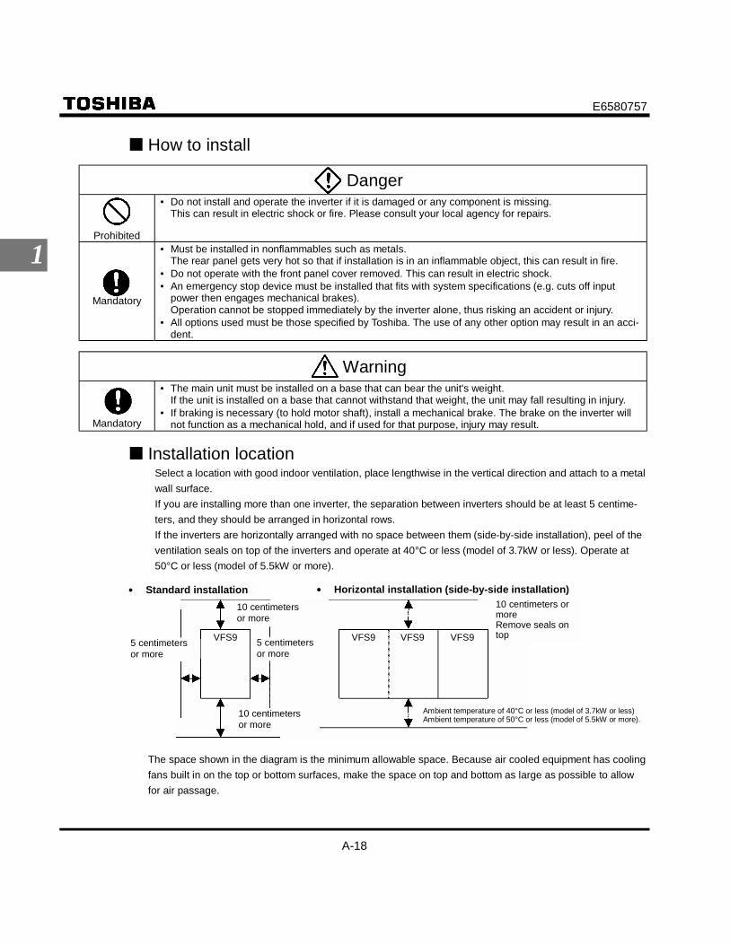
Installation locationSelect a location with good indoor ventilation, place lengthwise in the vertical direction and attach to a metalwall surface.If you are installing more than one inverter, the separation between inverters should be at least 5 centime-ters, and they should be arranged in horizontal rows.If the inverters are horizontally arranged with no space between them (side-by-side installation), peel of theventilation seals on top of the inverters and operate at 40°C or less (model of 3.7kW or less). Operate at50°C or less (model of 5.5kW or more).
•••• Standard installation
5 centimetersor more
•••• Horizontal installation (side-by-side installation)10 centimetersor more
10 centimeters ormoreRemove seals ontop
Ambient temperature of 40°C or less (model of 3.7kW or less)Ambient temperature of 50°C or less (model of 5.5kW or more).
5 centimetersor more
10 centimetersor more
VFS9 VFS9 VFS9 VFS9
The space shown in the diagram is the minimum allowable space. Because air cooled equipment has coolingfans built in on the top or bottom surfaces, make the space on top and bottom as large as possible to allowfor air passage.

E6580757
A-19
1
Note: Do not install in any location where there is high humidity or high temperatures and where there arelarge amounts of dust, metallic fragments and oil mist. If you are going to install the equipment in anyarea that presents a potential problem, please consult with Toshiba before doing so.
Calorific values of the inverter and the required ventilationThe energy loss when the inverter converts power from AC to DC and then back to AC is about 5 percent. Inorder to suppress the rise in temperature inside the cabinet when this loss becomes heat loss, the interior ofthe cabinet must be ventilated and cooled.
The amount of forcible air cooling ventilation required and the necessary heat discharge surface quantitywhen operating in a sealed cabinet according to motor capacity are as follows.
Calorific ValuesVoltage Class
Operating motorcapacity
(kW)Inverter Type Carrier
frequency4kHz
Carrierfrequency
12kHz
Amount of forcible aircooling ventilation re-
quired (m3/min)
Heat discharge surfacearea required for sealed
storage cabinet(m2)
0.2 2002PL 23 29 0.23 0.80.4 2004PL 47 60 0.29 1.00.75 2007PL 74 88 0.40 1.41.5 2015PL 142 169 0.60 2.1
Single-Phase200V Class
2.2
VFS9S-
2022PL 239 270 0.80 2.80.2 2002PM 21 26 0.23 0.80.4 2004PM 43 54 0.29 1.00.75 2007PM 67 79 0.40 1.41.5 2015PM 131 150 0.60 2.12.2 2022PM 168 195 0.80 2.83.7 2037PM 330 374 1.2 4.35.5 2055PL 450 510 1.7 6.17.5 2075PL 576 635 2.3 8.1
11 2110PM 750 820 3.4 12.0
Single-Phase200V Class
15
VFS9-
2150PM 942 1035 4.6 16.00.75 2007PL 44 57 0.40 1.41.5 2015PL 77 99 0.60 2.12.2 2022PL 103 134 0.80 2.83.7 2037PL 189 240 1.2 4.35.5 2055PL 264 354 1.7 6.17.5 2075PL 358 477 2.3 8.1
11 2110PL 490 650 3.4 12.0
Three-Phase400V Class
15
VFS9-
2150PL 602 808 4.6 16.0
Notes1) The heat loss for the optional external devices (input reactor, DC reactor, radio noise reduction filters,
etc.) is not included in the calorific values in the table.2) Case of 100% Load Continuation operation.
Panel designing taking into consideration the effects of noise.The inverter generates high frequency noise. When designing the control panel setup, consideration must begiven to that noise. Examples of measures are given below.• Wire so that the main circuit wires and the control circuit wires are separated. Do not place them in the
same conduit, do not run them parallel, and do not bundle them.• Provide shielding and twisted wire for control circuit wiring.• Separate the input (power) and output (motor) wires of the main circuit. Do not place them in the same
conduit, do not run them parallel, and do not bundle them.
• Ground the inverter ground terminals ( ).

E6580757
A-20
1
• Install surge suppressor on any magnetic contactor and relay coils used around the inverter.• Install noise filters if necessary.• Install EMC plate (attached as standard) and shielded wires fit with the EMC plate.
EMC plate
Installing more than one unit in a cabinetIf you are installing two or more inverters in one cabinet, pay attention to the following.
• Ensure a space of at least 5 centimeters on the left and right sides of the inverters.* If the inverters are horizontally arranged with no space between them (side-by-side installation), re-
move the ventilation seals on top of the inverters and operate at 40°C or less (model of 3.7kW or less)or 50°C (model of 5.5kW or more).
• Ensure a space of at least 20 centimeters on the top and bottom of the inverters.• Install an air deflecting plate so that the heat rising up from the inverter on the bottom does not affect the
inverter on the top.
Ventilation fan
Inverter
Air deflecting plate
Inverter

E6580757
B-1
2
2. Connection equipment
Danger
Disassemblyprohibited
• Never disassemble, modify or repair. This can result in electric shock, fire and injury. For repairs, callyour sales agency.
Prohibited
• Don’t stick your fingers into openings such as cable wiring hole and cooling fan covers. This can resultin electric shock or other injury.
• Don't place or insert any kind of object into the inverter (electrical wire cuttings, rods, wires). This canresult in electric shock or fire.
• Do not allow water or any other fluid to come in contact with the inverter. That may result in electricshock or fire.
Warning
Prohibited
• When transporting or carrying, do not hold by the front panel covers.The covers may come off and the unit will drop out resulting in injury.
2.1 Cautions on wiring
Danger
Prohibited
• Never remove the front cover when power is on or open door if enclosed in a cabinet.The unit contains many high voltage parts and contact with them will result in electric shock.
Mandatory
• Turn power on only after attaching the front cover or closing door if enclosed in a cabinet.If power is turned on without the front cover attached or closing door if enclosed in a cabinet. This canresult in electric shock or other injury.
• Electrical construction work must be done by a qualified expert.Connection of input power by someone who does not have that expert knowledge may result in fire orelectric shock.
• Connect output terminals (motor side) correctly.If the phase sequence is incorrect, the motor will operate in reverse and that may result in injury.
• Wiring must be done after installation.If wiring is done prior to installation that may result in injury or electric shock.
• The following steps must be performed before wiring.(1) Shut off all input power.(2) Wait at least ten minutes and check to make sure that the charge lamp is no longer lit.(3) Use a tester that can measure DC voltage (800VDC or more), and check to make sure that the
voltage to the DC main circuits (across PA-PC) is 45V or less.If these steps are not properly performed, the wiring will cause electric shock.
• Tighten the screws on the terminal board to specified torque.If the screws are not tightened to the specified torque, it may lead to fire.

E6580757
B-2
2
Danger
Be Grounded
• Ground must be connected securely.If the ground is not securely connected, it could lead to electric shock or fire when a malfunction or cur-rent leak occurs.
Warning
Prohibited
• Do not attach devices with built-in capacitors (such as noise filters or surge absorber) to the output(motor side) terminal.This could cause a fire.
Preventing radio noiseTo prevent electrical interference such as radio noise, separately bundle wires to the main circuit's powerterminals (R/L1, S/L2, T/L3) and wires to the motor terminals (U/T1, V/T2, W/T3).
Control and main power supplyThe control power supply and the main circuit power supply for the VFS9 are the same.If a malfunction or trip causes the main circuit to be shut off, control power will also be shut off. Whenchecking the cause of the malfunction or the trip, use the trip holding retention selection parameter.
Wiring• Because the space between the main circuit terminals is small use sleeved pressure terminals for the
connections. Connect the terminals so that adjacent terminals do not touch each other.• For ground terminal use wires of the size that is equivalent to or larger than those given in table 10.1
and always ground the inverter (200V voltage class: D type ground [former type 3 ground]; 400V class: Ctype ground [former special type 3 ground]).Use as large and short a ground wire as possible and wire it as close as possible to the inverter.
• See the table in 9-1 for wire sizes.• The length of the main circuit wire in 10-1 should be no longer than 30 meters. If the wire is longer than
30 meters, the wire size (diameter) must be increased.
E6580757
B-3
2
2.2 Standard connections
Danger
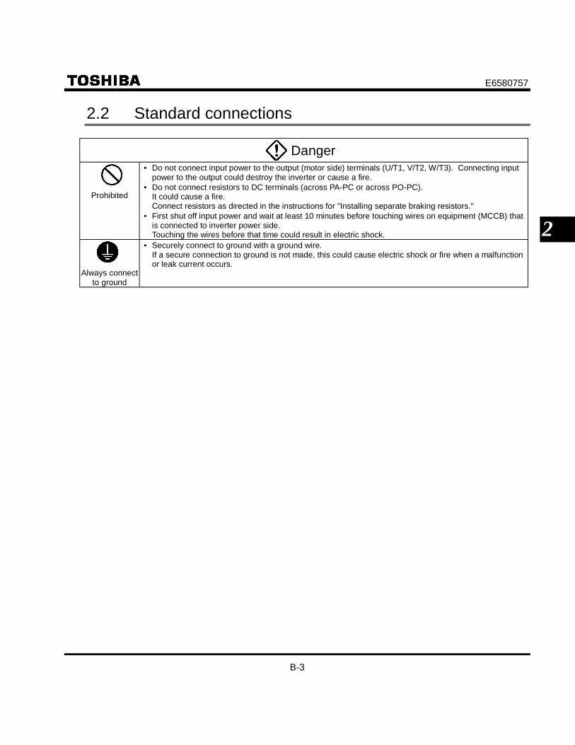
Prohibited
• Do not connect input power to the output (motor side) terminals (U/T1, V/T2, W/T3). Connecting inputpower to the output could destroy the inverter or cause a fire.
• Do not connect resistors to DC terminals (across PA-PC or across PO-PC).It could cause a fire.Connect resistors as directed in the instructions for "Installing separate braking resistors."
• First shut off input power and wait at least 10 minutes before touching wires on equipment (MCCB) thatis connected to inverter power side.Touching the wires before that time could result in electric shock.
Always connectto ground
• Securely connect to ground with a ground wire.If a secure connection to ground is not made, this could cause electric shock or fire when a malfunctionor leak current occurs.

E6580757
B-4
2
2.2.1 Standard connection diagram 1- sink (common: CC)
This diagram shows a standard wiring of the main circuit.
MCCBR/L1S/L2
*1
U/T1V/T2W/T3
FLC
FLB
FLA
RY
RC
F
R
RST
S1
S2
S3
CC
I I
P24
OUT
FM CC VIA VIB PP
+ +
+
-
-
P0 PA PB PC
Ry
VF-S9
MCCB(2P)R/L1
S/L2
JP30
1
JP30
1A
JP30
2
DC reactor (DCL)*2 (option) Braking resistor
(option)
Main circuitFilter
Main circuit power supply200V class: single-phase 200 ~ 240V-50/60Hz three-phase 200 ~ 230V-50/60Hz400V class: three-phase 380 ~ 500V-50/60Hz
Motor
Operation panel
Control circuit
Meter
Forward
Fault detectionrelay
Low-speeddetection signal
Reverse
Reset
Presetspeed2
Presetspeed1
Frequency
meter
Presetspeed3
Current signal: 4 ~ 20mA
Voltage signal: 0 ~ 10V
External potentiometer(or input voltage signal acrossVIA-CC terminals: 0 ~ 10V)*The VIA terminal and II terminal cannot be used at the same time.
*1 1-phase series don't have T/L3 terminal.*2 The PO-PA terminals are shorted by a bar when shipped from the factory. Before installing the DC reactor (DCL), remove the bar.
FMC SINK
SOURCEFMV
Connector forcommon serial communications
Power supply1φ200 ~ 240V-50/60Hz
IM
Common
Designated frequencyattainment signal
T/L3

E6580757
B-5
2
2.2.2 Standard connection diagram 2- source (common: P24)
DC reactor (DCL)*2 (option) Braking resistor
(option)
Main circuitFilter
Main circuit power supply200V class: single-phase 200 ~ 240V-50/60Hz three-phase 200 ~ 230V-50/60Hz400V class: three-phase 380 ~ 500V-50/60Hz
MCCBR/L1S/L2T/L3
U/T1 Motor
Operation panel
Control circuit
Meter
IM
Forward
Reverse
Reset
Presetspeed2
Presetspeed1
Frequency
meter
Presetspeed3
Current signal: 4 ~ 20mA
Voltage signal: 0 ~ 10V
External potentiometer(or input voltage signal acrossVIA-CC terminals: 0 ~ 10V)*The VIA terminal and II terminal cannot be used at the same time.
*1 1-phase series don't have T/L3 terminal.*2 The PO-PA terminals are shorted by a bar when shipped from the factory. Before installing the DC reactor (DCL), remove the bar.
V/T2W/T3
FLC
FLB
FLA
RY
RC
P24
F
R
RST
S1
S2
S3
I I
CC
OUT
+ +
-
-
P0
*1
PA PB PC
RyFMC SINK
SOURCEFMV
Connector forcommon serial communications
VF-S9
JP30
1
JP30
1A
JP30
2
MCCB(2P)Power supply1φ200 ~ 240V-50/60Hz
R/L1
S/L2
FM CC VIA VIB PP
Fault detectionrelay
Low-speeddetection signal
Designated frequencyattainment signal

E6580757
B-6
2
2.3 Description of terminals
2.3.1 Main circuit terminalsThis diagram shows an example of wiring of the main circuit. Use options if necessary.
Power supply and motor connections
VF-S9
E
R/L1
Power supply
Circuit
Note) Model of 3-phase 200V-0.2, 0.4, 0.75kW don't have grounding terminal.Ground connecting to flame of inverter.
: Flame grounding
Motor
Power lines areconnected to R.,S. and T.
Motor lines areconnected to U., V. and W.
S/L2 T/L3 U/T1 V/T2 W/T3
Connections with peripheral equipment
Powersupply
No-fusebreaker
Magneticcontactor
Inputreactor
Noisereduction filter
Braking resistor DC reactor
Zero-phasereactor
Motor-end surge voltagesuppression filter
Motor‚ q/L1
‚ r/L2
‚ s/L3
PB PA PO
‚ u/T2
‚ t/T1
‚ v/T3
IMInverter
E6580757
B-7
2
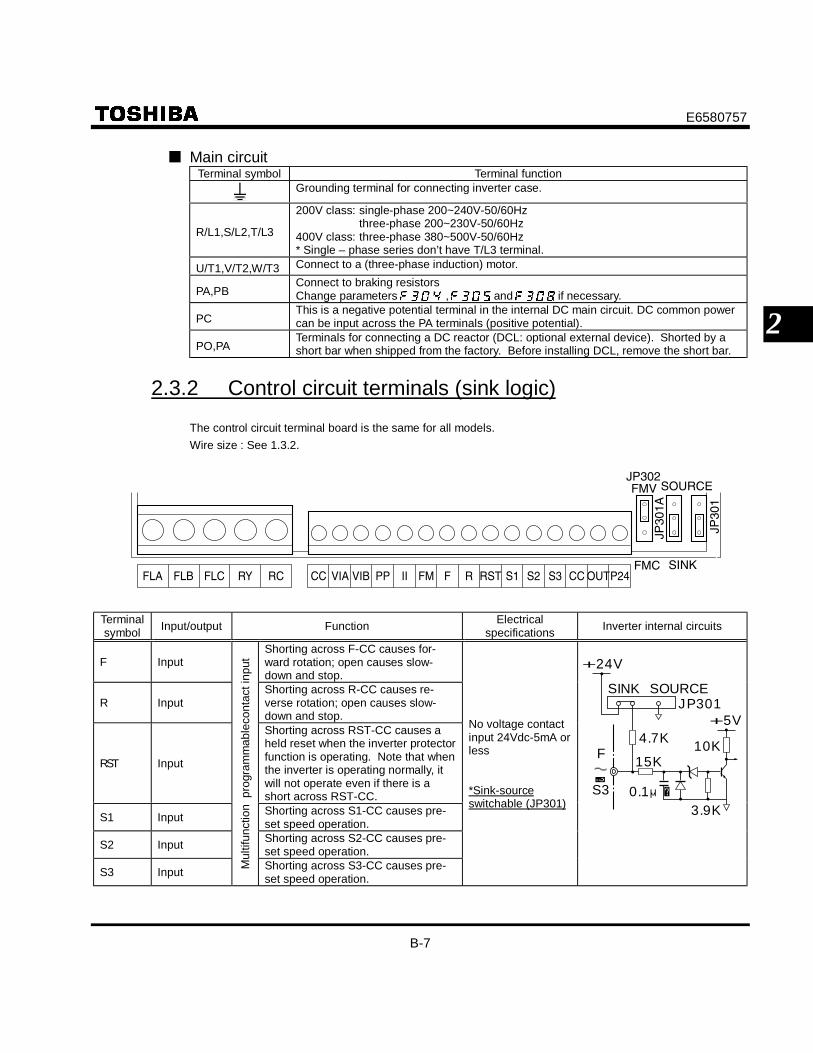
Main circuitTerminal symbol Terminal function
Grounding terminal for connecting inverter case.
R/L1,S/L2,T/L3
200V class: single-phase 200~240V-50/60Hzthree-phase 200~230V-50/60Hz
400V class: three-phase 380~500V-50/60Hz* Single – phase series don’t have T/L3 terminal.
U/T1,V/T2,W/T3 Connect to a (three-phase induction) motor.
PA,PBConnect to braking resistorsChange parameters , and if necessary.
PCThis is a negative potential terminal in the internal DC main circuit. DC common powercan be input across the PA terminals (positive potential).
PO,PATerminals for connecting a DC reactor (DCL: optional external device). Shorted by ashort bar when shipped from the factory. Before installing DCL, remove the short bar.
2.3.2 Control circuit terminals (sink logic)
The control circuit terminal board is the same for all models.Wire size : See 1.3.2.
FLA FLB FLC RY RC CC VIA VIB PP II FM F R RST S1 S2 S3 CC OUTP24FMC SINK
FMV SOURCEJP302
JP30
1A
JP30
1
Terminalsymbol Input/output Function Electrical
specifications Inverter internal circuits
F InputShorting across F-CC causes for-ward rotation; open causes slow-down and stop.
R InputShorting across R-CC causes re-verse rotation; open causes slow-down and stop.
RST Input
Shorting across RST-CC causes aheld reset when the inverter protectorfunction is operating. Note that whenthe inverter is operating normally, itwill not operate even if there is ashort across RST-CC.
S1 Input Shorting across S1-CC causes pre-set speed operation.
S2 Input Shorting across S2-CC causes pre-set speed operation.
S3 Input Mul
tifun
ctio
n p
rogr
amm
able
cont
act i
nput
Shorting across S3-CC causes pre-set speed operation.
No voltage contactinput 24Vdc-5mA orless
*Sink-sourceswitchable (JP301)
F〜
S3
4.7K
JP301
+24V
SINK SOURCE
+5V
0.1μ3.9K
10K15K

E6580757
B-8
2
Terminalsymbol Input/output Function Electrical
specifications Inverter internal circuits
CC Common toInput/output Control circuit's common terminal
PP Output Analog input setting power output10Vdc (permissibleload current:10mAdc)
PP
+24V
I I* Input
Multifunction programmable analog input.Standard default setting: 4(0)~20mAdc in-put and 0~50Hz (50Hz setting) or 0~60Hz(60Hz setting) frequency
4-20mA(internal imped-ance: 400Ω)
V I A* Input
Multifunction programmable analog input.Standard default setting: 0~10Vdc inputand 0~80Hz frequency
10Vdc(internal imped-ance: 30kΩ)
15KVIA
I I
15K
1K
+5V
150 250
VIB Input
Multifunction programmable analog input.Standard default setting: 0~10Vdc inputand 0~50Hz(50Hz setting) or0~60Hz(60Hz setting) frequency.
10Vdc(internal imped-ance: 30kΩ)
15K
+5V
VIB
15K0.1
FM Output
Multifunction programmable analog out-put. Standard default setting: output cur-rent. Connect a 1mAdc full-scale amme-ter or 7.5Vdc (10Vdc)-1mA full-scale volt-meter. Can change to 0-20mA (4-20mA)by jumper JP302 switching.
1mA full-scale DCammeter or 7.5Vdc1mA full-scale dcvoltmeter
0-20mA (4-20mA)full scale DC am-meter
FM
FMV
FMC
JP302
4.7K
33K29K
100K
0.01μ
0.01μ
100100
+24V
20K
18K
10K
100K
100K20K
CC Common toInput/output Control circuit's common terminal
P24 Output 24Vdc power output 24Vdc-100mAPTC
+24V
P24
* The VIA terminal and II terminal cannot be used at the same time.

E6580757
B-9
2
Terminalsymbol Input/output Function Electrical
specifications Inverter internal circuits
OUT Output
Multifunction programmable open collectoroutput. Standard default settings detectand output speed reach signal output fre-quencies.
Open collector out-put : 24Vdc-50mA
*Sink-sourceswitchable(JP301A)
RCRY Output
Multifunction programmable relay contactoutput. Contact ratings: 250Vac -2A (cosφ= 1), 30Vdc-1A, 250Vac-1A (cosφ = 0.4).Standard default settings detect and out-put low-speed signal output frequencies.
250Vac-2A (cosφ =1): at resistance load30Vdc-1A: 250Vac-1A (cosφ= 0.4)
RC
+24V
RYRY
FLAFLBFLC
Output
Multifunction programmable relay contactoutput. Contact ratings: 250Vac -2A (cosφ= 1), 30Vdc-1A, 250Vac-1A (cosφ = 0.4).Detects the operation of the inverter'sprotection function. Contact across FLA-FLC is closed and FLB-FLC is openedduring protection function operation.
250Vac-2A (cosφ =1): at resistance load30Vdc-1A: 250Vac-1A (cosφ= 0.4)
FLB
FLC
FLA +24V
RY
150+5V
+24V
OUT
JP301SOURCE
1010
150
FUSE

E6580757
B-10
2
Sink logic (negative common)/source logic (positive common)logic switching of input output terminals
Current flowing out turns control input terminals on. These are called sink logic terminals (The end of Type- form : AN / WN). The general used method in Europe is source logic in which current flowing into the in-put terminal turns it on(The end of Type - form : WP).
Sink logic Source logic
Input
InverterProgrammablecontroller
Common
Output
Common
Output
Input
InverterProgrammablecontroller
Common
Input
Output
InputCommon
Output

E6580757
B-11
2
Logic switching/voltage-current output switching (jumper)(1) Logic switching
JP301 : Input, JP301A : OutputSwitch logic before wiring to inverter and without supplying power. If sink and source are switched whenpower is supplied first after logic switching or while power is being input to the inverter, that will destroythe inverter. First check to make sure that switching is correct and then supply power.
(2) Voltage-current output switchingJP302Switch the Fm terminal's voltage-current output before wiring to inverter and without supplying power.
SOURCEFMV(voltage output) Case of
SINK logic
FMC(0~20maoutput) SINK
JP30
1
JP30
1A
JP30
2
* After switching sink-source logic make sure that switching again switching cannot be done easily.

E6580757
C-1
3
3. Operations Danger
Prohibited
• Do not touch inverter terminals when electrical power is connected to the inverter even if the motor isstopped.Touching the inverter terminals while power is connected to it may result in electric shock.
• Do not touch switches when the hands are wet and do not try to clean the inverter with a damp cloth.Such practices may result in electric shock.
• Do not go near the motor in alarm-stop status when the retry function is selected.The motor may suddenly restart and that could result in injury.Take measures for safety, e.g. attaching a cover to the motor, against accidents when the motor unex-pectedly restarts.
Mandatory
• Turn power on only after attaching the front cover or closing door if enclosed in a cabinet.If power is turned on without the front cover attached or closing door if enclosed in a cabinet, that mayresult in electric shock or other injury.
• If the inverter begins to emit smoke or an unusual odor, or unusual sounds, immediately turn power off.If the equipment is continued in operation in such a state, the result may be fire. Call your local salesagency for repairs.
• Always turn power off if the inverter is not used for long periods of time.• Turn input power on after attaching the front cover.
When enclosed inside a cabinet and using with the front cover removed, always close the cabinetdoors first and then turn power on. If the power is turned on with the front cover or the cabinet doorsopen, it may result in electric shock.
• Make sure that operation signals are off before resetting the inverter after malfunction.If the inverter is reset before turning off the operating signal, the motor may restart suddenly causinginjury.
Warning
Contactprohibited
• Do not touch heat radiating fins or discharge resisters. These device are hot, and you'll get burned ifyou touch them.
Prohibited
• Always observe the permissible operating ranges of motors and other equipment (see the instructionmanual for the motor).If these ranges are not observed, it could result in injury.

E6580757
C-2
3
3.1 How to operate the VF-S9
Overview of how to operate the inverter with simple examples.
Example 1 Setting the operation frequency using built-in potentiometer and run-ning and stopping using the operation panel.
(1) Wiring
IM
R/L1
S/L2T/L3
U/T1V/T2W/T3
PO PCPBPA
G
MCCB
Main circuit
Controlcircuit
Motor
(2) Parameter setting (default setting)Title Function Programmed value
Command mode selection 1Frequency setting mode selection 2
(3) Operation
Run/stop: Press the and keys on the panel.
Frequency setting: Set adjusting position of notches on the potentiometer.
E6580757
C-3
3
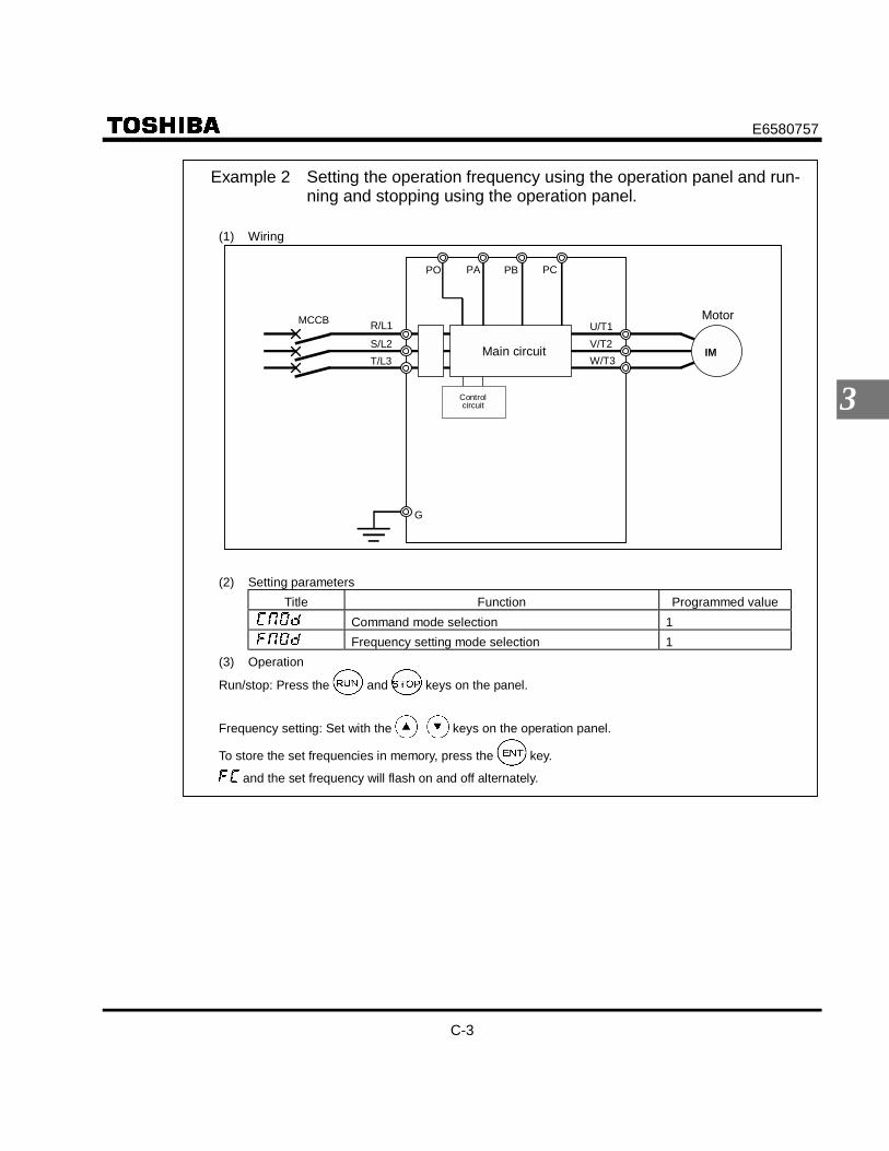
Example 2 Setting the operation frequency using the operation panel and run-ning and stopping using the operation panel.
(1) Wiring
IM
R/L1
S/L2T/L3
U/T1V/T2W/T3
PO PCPBPA
G
MCCB
Main circuit
Controlcircuit
Motor
(2) Setting parametersTitle Function Programmed value
Command mode selection 1Frequency setting mode selection 1
(3) Operation
Run/stop: Press the and keys on the panel.
Frequency setting: Set with the keys on the operation panel.
To store the set frequencies in memory, press the key.
and the set frequency will flash on and off alternately.

E6580757
C-4
3
Example 3 Setting the operation frequency using built-in potentiometer and run-ning and stopping using external signals.
(1) Wiring
Main circuit
Controlcircuit
Reverse rotation signal
Common
Motor
Forward rotation signal
IM
G
F
R/L1S/L2T/L3
U/T1V/T2W/T3
R
CC
PO PCPBPA
MCCB
(2) Parameter setting (default setting)Title Function Programmed value
Command mode selection 0Frequency setting mode selection 2
(3) OperationRun/stop: ON/OFF input to F-CC and R-CC. (Set JP301 to Sink logic)Frequency setting: Set adjusting position of notches on the potentiometer.

E6580757
C-5
3
Example 4 Operation frequency setting, running and stopping using externalsignals.
(1) Wiring
IM
F
R/L1S/L2
T/L3
U/T1V/T2
W/T3
R
PO PCPBPA
MCCB
CC
IIGCC VIBVIA PP
Main circuit
Controlcircuit
Reverse rotation signal
Common
Motor
Forward rotation signal
Current signal: 4 ∼ 20mA
Voltage signal: 0 ∼ 10VExternal potentiometer(or voltage signal to VIA-CC 0 ∼ 10V)
(2) Parameter settingTitle Function Programmed value
Command mode selection 0Frequency setting mode selection 0
(3) OperationRun/stop: ON/OFF input to F-CC and R-CC. (Set JP301 to Sink logic.)Frequency setting: VIA and VIB: 0-10Vdc (external potentiometer)
II : Input 4-20mAdc.Note) The VIA terminal and II terminal cannot be used at the same time.

E6580757
C-6
3
3.2 Simplified Operation of the VF-S9
The procedures for setting operation frequency and the methods of operation can be selected from the following.
Run / stop :(1) Run and stop using external signals to the terminal
board(2) Run and stop from the operation panel
Frequency setting :(1) Setting using external signals to the terminal board
(0-10Vdc, 4-20mAdc)(2) Setting using the operation panel(3) Setting using the potentiometer on the inverter
main unitUse the basic parameters (command mode selection) and (frequency setting mode selection)for selecting.
Title Function Adjustment range Default settingCommand mode selection 0: Terminal board; 1: Operation panel 1Frequency setting modeselection
0: Terminal board; 1: Operation panel;2: Internal potentiometer 2
[Steps in setting parameters]Key operated LED display Operation
Displays the operation frequency (operation stopped). (When standardmonitor display selection is set to [Operation frequency])
Press the MON key to display the first basic parameter(automatic acceleration/deceleration).
Press either the key or the key to select " ."
Press the ENTER key to display the parameter setting. (Standard defaultsetting: )
Change the parameter to (Terminal board) by pressing the key.
Press the ENTER key to save the changed parameter. and theparameter set value are displayed alternately.
Press either the key or the key to select " ."
Press the ENTER key to display the parameter setting. (Standard defaultsetting: )
Change the parameter to (Operation panel) by pressing the key
Press the ENTER key to save the changed parameter. and theparameter set value are displayed alternately.
* Pressing the MON key twice returns the display to standard monitor mode (displaying operation frequency).

E6580757
C-7
3
3.2.1 How to start and stop(1) Start and stop using the operation panel keys ( )
Use the and keys on the operation panel to start and stop the motor.
RUN: Motor starts.
STOP: Motor stops (slowdown stop).
(2) Start and stop using external signals to the terminal board ( )Use external signals to the inverter terminal board to start and stop the motor. (Set JP301 to sink logic)
Short F and CC terminals:run forward
Open F and CC terminals:slow down and stop
* Coast stopThe standard default setting is for slowdown stop. Tomake a coast stop, assign an ST terminal function toan idle terminal using the programmable terminalfunction. And set the :ST signal selection.For coast stop, open the ST-CC when stopping themotor in the state described at left. The monitor onthe inverter at this time will display .
3.2.2 How to set the frequency(1) Setting the frequency using the potentiometer on the inverter main unit
( )Set the frequency with the notches on the potentiometer.
Move clockwise through the highernotches for the higher frequencies.
Motor speed Coast stop
ST-CC
F-CCFrequency
F-CC
Slowdown stop
ONOFF

E6580757
C-8
3
(2) Setting the frequency using the operation panel ( )Set the frequency from the operation panel.
: Moves the frequency up
: Moves the frequency down
Example of operating a run from the panelKey operated LED display Operation
Displays the operation frequency.(When standard monitor display selection is set to 0 [opera-tion frequency])
Set the operation frequency.
Press the ENT key to save the operation frequency. and the setfrequency are displayed alternately.
Pressing the key or the key will change the operation frequencyeven during operation.
(3) Setting the frequency using external signals to the terminal board ( )
Frequency setting1) Setting the frequency using external potentiometer
* The input terminal VIB can be used in the same way and VIA and VIB are automaticallyswitched by the default settings. Set parameters to specify priority. For more details, see6.5.
Note:The VIA terminal and II terminal cannot be used at the same time.
* Potentiometer controlSet frequency using the potentiometer (1~10kΩ-1/4W)For more detailed information on adjustments,see 6.5.
Setting frequency usingthe potentiometer
Frequency
50Hz or 60HzB

E6580757
C-9
3
2) Setting the frequency using input voltage (0~10V)
* The input terminal VIB can be used in the same way. VIA and VIB are automatically switchedby the default settings. Set parameters to specify priority. For more details, see 6.5.
Note:The VIA terminal and II terminal cannot be used at the same time.
3) Setting the frequency using current input (4~20mA)
* Setting of parameters also allow 0-20mAdc.Note:The VIA terminal and II terminal cannot be used at the same time.
* voltage signalSetting frequency using voltage signals (0~10V). Formore detailed information on adjustments, see 6.5.
Voltage signal 0-10Vdc
Frequency
* Current signalSetting frequency using current signals (4~20mA). Formore detailed information on adjustments, see 6.5.
Current signal 4-20mAdc
Frequency
50Hz or 60Hz
50Hz or 60Hz

E6580757
D-1
4
4. Basic VF-S9 operationsThe VF-S9 has the following three monitor modes.
Standard monitor mode : The standard inverter mode. This mode is enabled wheninverter power goes on.
This mode is for monitoring the output frequency and setting the frequency desig-nated value. In it is also displayed information about status alarms during running andtrips.
• Setting frequency designated values - see 3.2.2• Status alarm
If there is an error in the inverter, the alarm signal and the frequency will flashalternately in the LED display.
: When a current flows at or higher than the overcurrent stall level. : When a voltage is generated at or higher than the over voltage stall
level. : When a load reaches 50% or higher of the overload trip value. : When temperature inside the inverter rises to the overheating protec-
tion alarm level.Model of 3.7kW or less : about 115°C.Model of 5.5kW or more : about 92°C
Setting monitor mode : The mode for setting inverter parameters.
For more on how to set parameters, see 4.1.
Status monitor mode : The mode for monitoring all inverter status.Allows monitoring of set frequencies, output current/voltage and terminalinformation.
For more on how to use the monitor, see 8.1.
Pressing the key will move the inverter through each of the modes.
Standard monitor mode
Status monitor mode Setting monitor mode

E6580757
D-2
4
4.1 How to set parameters Setting monitor mode
The standard default parameters are programmed before the unit is shipped from the factory. Parameters can bedivided into three major categories. Select the parameter to be changed or to be searched and retrieved.
Basic parameters : The basic parameters that must be programmed be-fore the first use.
Extended parameters : The parameters for detailed and special setting.
User parameters
(automatic edit function)
: Indicates parameters that are different from the stan-dard default setting parameters. Use them to checkafter setting and to change setting.(Parameter title: )
Setup parameters : When the standard setting is entered, thisparameter is displayed.
* Adjustment range of parameters : An attempt has been made to assign a value that is higher than the programmable range. Or, as a
result of changing other parameters, the programmed value of the parameter that is now selectedexceeds the upper limit.
: An attempt has been made to assign a value that is lower than the programmable range. Or, as aresult of changing other parameters, the programmed value of the parameter that is now selectedexceeds the lower limit.
If the above alarm is flashing on and off, no setting can be done of values that are equal to or greaterthan or equal to or lower than .While these codes are flashing on and off, no change can be made to any parameter.
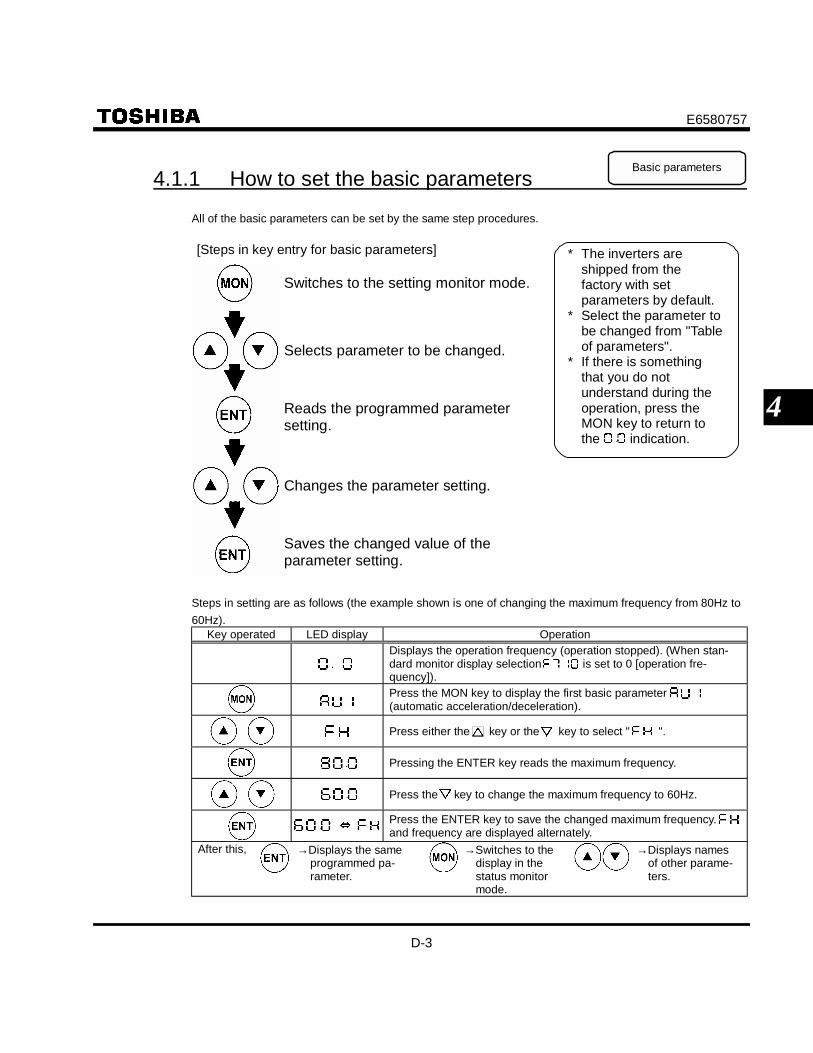
E6580757
D-3
4
4.1.1 How to set the basic parameters Basic parameters
All of the basic parameters can be set by the same step procedures.
Switches to the setting monitor mode.
* The inverters areshipped from thefactory with setparameters by default.
* Select the parameter tobe changed from "Tableof parameters".
* If there is somethingthat you do notunderstand during theoperation, press theMON key to return tothe indication.
Reads the programmed parametersetting.
Saves the changed value of theparameter setting.
Selects parameter to be changed.
Changes the parameter setting.
[Steps in key entry for basic parameters]
Steps in setting are as follows (the example shown is one of changing the maximum frequency from 80Hz to60Hz).
Key operated LED display OperationDisplays the operation frequency (operation stopped). (When stan-dard monitor display selection is set to 0 [operation fre-quency]).Press the MON key to display the first basic parameter (automatic acceleration/deceleration).
Press either the key or the key to select " ".
Pressing the ENTER key reads the maximum frequency.
Press the key to change the maximum frequency to 60Hz.
Press the ENTER key to save the changed maximum frequency. and frequency are displayed alternately.
After this, →Displays the sameprogrammed pa-rameter.
→Switches to thedisplay in thestatus monitormode.
→Displays namesof other parame-ters.

E6580757
D-4
4
4.1.2 How to set extended parameters
The VF-S9 has extended parameters to allow you to make full use of its functions. All extended parametersare expressed with F and three digits.
Press the MON key once and use the key and the key to selectfrom the basic parameters.
Basic parameter
Press the key and the keyto select the parameter to bechanged. Then, press theENTER key to display the setparameter.
Switches to the setting monitor mode. (displays )
[Steps in key entry for extended parameters]
Selects the extended parameter to be changed.
Changes the parameter setting.
Saves the changed value of the extended parameter setting.
Pressing the key instead of the key moves back to the previous status.
Selects " " from basic parameters.
Displays the first extended parameter.
Reads the programmed parameter setting.
:
:
:
:
:
:
:

E6580757
D-5
4
Example of parameter settingThe steps in setting are as follows.Example of changing the dynamic braking selection from 0 to 1.
Key operated LED display OperationDisplays the operation frequency (operation stopped). (When stan-dard monitor display selection is set to [operation fre-quency])Press the MON key to display the first basic parameter (automatic acceleration/deceleration).Press either the key or the key to change to the parametergroup .Press the ENTER key to display the first extended parameter
Press the key to change to the dynamic braking selection .
Pressing the ENTER key allows the reading of parameter setting.
Press the key to change the dynamic braking selection from to .Pressing the ENTER key alternately flashes on and off the parameterand changed value and allows the save of those values.
If there is anything you do not understand during this operation, press the MON key several times tostart over from the step of display.
4.1.3 Search and resetting of changed parameters
Automatically searches for only those parameters that are programmed with values different from the stan-dard default setting and displays them in the user parameter group . Parameter setting can also bechanged within this group.
Notes on operation• When a value is reprogrammed that is the same as the standard value, there will be no display within
.• The parameters programmed by the setup parameter are also displayed as changed parameters.

E6580757
D-6
4
How to search and reprogram parametersThe operations of search and resetting of parameters are as follows.
Key operated LED display OperationDisplays the operation frequency (operation stopped). (When stan-dard monitor display selection is set to [operation fre-quency])Press the MON key to display the first basic parameter (automatic acceleration/deceleration).
Press either the key or the key to select " ".
Press the ENTER key to enable the user parameter automatic editfunction.
or ↓
Searches for parameters that are different in value from the standarddefault setting and displays those parameters. Press the ENTER keyor the key to change the parameter displayed. (Pressing the key moves the search in the reverse direction).
Press the ENTER key to display the set value.
Press the key and key to change set value.
Press the ENTER key to save the changed value. The parametername and the programmed value will flash on and off alternately.Use the same steps as those given above to display parameters thatyou want to search for or change setting with the key and key.
When appears again, the search is ended.
Parameterdisplay
↓
↓
A search can be canceled by pressing the MON key. Press the MONkey once while the search is underway to return to the display of pa-rameter setting mode.After that you can press the MON key to return to the status monitormode or the standard monitor mode (display of operation frequency).
If there is something that you do not understand during this operation, press the key severaltimes and start over again from the step of display.

E6580757
D-7
4
4.1.4 How to program setup parameters Setup parameters
When the standard parameter is set to (standard default setting), the setup parameter is displayed.Setting the setup parameter enable to operate.The setup parameter selects either 50Hz or 60Hz for the base motor frequency.Set this in line with the specifications of the motor.The setup parameters automatically program the base motor frequency and related parameters, but thoseparameters can be reprogrammed later.The steps in setting are as follows
Key operated LED display OperationDisplays the base motor frequency.
Press either the key or the key to select 50Hz or 60Hz.
Press the ENTER key to set the base motor frequency and related pa-rameters. will be displayed during the setting.Displays the operation frequency (while stopped)
Setting of the following parameters can be changed by the setup parameters.They are displayed as changed parameters during searches .If select of 60Hz, and are not displayed as changed parameters.
Setting value 50 60Title Function Setting value
Upper limit frequency 50Hz 60Hz
Base frequency 1 50Hz 60Hz(Standard)
Base frequency 2 50Hz 60Hz(Standard)
Frequency at VIA input point 2 50Hz 60Hz
Frequency at VIB input point 2 50Hz 60Hz

E6580757
D-8
4
4.1.5 Parameters that cannot be changed while running
For reasons of safety, the following parameters have been set up so that they cannot be reprogrammed whilethe inverter is running.
Basic parameters(Automatic acceleration/deceleration)(Automatic torque boost)(Automatic environment setting)(Automatic function setting)(Command mode selection)(Frequency setting mode selection)(Maximum frequency)(Default setting)(V/F control mode selection)(Electronic thermal protection characteristics selection)
Extended parametersSupply voltage correctionAuto-tuningRated capacity ratio of motor to inverter
4.1.6 Returning all parameters to standard default setting
Setting the standard default setting parameter to 3, all parameters can be returned to the those factorydefault settings. (Except for )When is set to , the set up parameter is displayed. Setting the setup parameter enable to operate,See 4.1.4.Note: For more details on the standard default setting parameter , see 5.7.
Notes on operation• We recommend that before this operation you write down on paper the values of those parameters,
because when setting to 3, all parameters with changed values will be returned to standardfactory default setting.
Set , and and canbe changed while the inverter is running.

E6580757
D-9
4
Steps for returning all parameters to standard default settingKey operated LED display Operation
Displays the operation frequency (perform during operation stopped).
Press the MON key to display the first basic parameter (automatic acceleration/deceleration).
Press the key or the key to change to .
Pressing the ENTER key displays the programmed parameters.( will always display zero " " on the right, the previous set-ting on the left.)Press the key or the key to change the set value. To return tostandard factory default setting, change to " ".Pressing the ENTER key displays " " while returning all pa-rameters to factory default setting.The monitor returns to the display of setup parameters.Set the setup parameters. See. 4.1.4.
If there is something that you do not understand during this operation, press the MON key severaltimes and start over again from the step of display.

E6580757
E-1
5
5. Basic parametersBefore you operate the inverter, the parameters that you must first program are the basic parameters.
5.1 Setting acceleration/deceleration time
: Automatic acceleration/deceleration
: Acceleration time 1
: Deceleration time 1
• Function1) For acceleration time , program the time that it takes for the inverter output frequency to go from
0Hz to maximum frequency .2) For deceleration time , program the time that it takes for the inverter output frequency to go from
maximum frequency to 0Hz.
5.1.1 Automatic acceleration/deceleration
This automatically adjusts acceleration and deceleration time in line with load size.
* Automatically adjusts acceleration and deceleration time within the inverter rated current in a range thatgoes from 1/8 to infinity of programmed and time. It goes to the optimum value taking a mar-ginal allowance into consideration.
* Automatically adjusts to the shortest time within 120% of the inverter rated current. It is a value that is ob-tained attaching importance to acceleration/deceleration time.
Acceleration time Deceleration time
When load is small
Acceleration/deceleration time→ increase
When load is large
Acceleration/deceleration time→ decrease
Outputfrequency (Hz)
Time (s)
Acceleration time Deceleration time
Time (s)
Outputfrequency (Hz)
Set (automatic acceleration/deceleration) to or .

E6580757
E-2
5
[Parameter setting]Title Function Adjustment range Default setting
Automatic acceleration/deceleration0: Disabled (manual)1: Optimum rate2: Minimum rate
0
When automatically setting acceleration/deceleration time, always change the acceleration/decelerationtime so that it conforms with the load. For inverters that requires a fixed acceleration/deceleration time, usethe manual settings ( , ).
Setting acceleration/deceleration time ( , ) in conformance with mean load allows optimumsetting that conforms to further changes in load.
Use this parameter after actually connecting the motor. Acceleration may not be complete if the load is such that the inverter is operated in the rated current vicin-
ity. If acceleration is incomplete, set acceleration/deceleration time manually ( ).
Methods of setting automatic acceleration/decelerationKey operated LED display Operation
Displays the operation frequency. (When standard monitor displayselection is set to [operation frequency]).Press the MON key to display the first basic parameter(automatic acceleration/deceleration).
Press the ENTER key to display the parameter setting.
Press the key to change the parameter to or .
Press the ENTER key to save the changed parameter. andthe parameter are displayed alternately.
5.1.2 Manually setting acceleration/deceleration time
Set acceleration time from 0Hz operation frequency to maximum frequency and deceleration time as thetime when operation frequency goes from maximum frequency to 0Hz.
Outputfrequency (Hz)
Time (s)
(manual setting)
[Parameter setting]Title Function Adjustment range Default setting
Acceleration time 1 0.1-3600 seconds 10.0
Deceleration time 1 0.1-3600 seconds 10.0

E6580757
E-3
5
If the programmed value is shorter than the optimum acceleration/deceleration time determined by loadconditions, overcurrent stall or overvoltage stall function may make the acceleration/deceleration timelonger than the programmed time. If an even shorter acceleration/deceleration time is programmed, theremay be an overcurrent trip or overvoltage trip for inverter protection. (for further details, see 13.1).
5.2 Increasing starting torque
: Automatic torque boost
• FunctionSimultaneously switches inverter output (V/F) control and programs motor constants automatically (On-line automatic-tuning function) to improve torque generated by the motor. This parameter integrates thesetting of special V/F control selection such as vector control.
Title Function Adjustment range Default setting
Automatic torque boost 0: Disabled1: Sensorless vector control + auto-tuning 0
Note:Parameter displays on the right always return to 0 after setting. The pervious setting is displayed on the left.Ex.
1) When using vector control (increasing starting torque and high-precision opera-tions)
Set the automatic control to (sensorless vector control + auto-tuning)
Setting automatic control to (sensorless vector control + auto-tuning) provides high starting torquebringing out the maximum in motor characteristics from the low-speed range. This suppresses changes inmotor speed caused by fluctuations in load to provide high precision operation. This is an optimum feature forelevators and other load transporting machinery.
[Methods of setting]Key operated LED display Operation
Displays the operation frequency. (Perform during operationstopped.) (When standard monitor display selection is set to [operation frequency])Press the MON key to display the first basic parameter(automatic acceleration/deceleration).Press the key to change the parameter to (automatic torqueboost).
Press the ENTER key to display the parameter setting.

E6580757
E-4
5
Key operated LED display OperationPress the key to change the parameter to 1 (sensorless vectorcontrol + auto-tuning).Press the ENTER key to save the changed parameter. andthe parameter are alternately displayed.
Note 1: Setting V/F control selection to (sensorless vector control) provides the same characteristics aswhen (auto-tuning) is set to 2. ⇒ See 5.12
Note 2: Setting to automatically programs to .
If vector control cannot be programmed....First read the precautions about vector control in 5.12, 6.1) If the desired torque cannot be obtained, see 6.13, 3.2) If auto-tuning error " " appears, see 6.13, 3.
(automatic torque boost) and (V/F control mode selection)Automatic torque boost is the parameter for setting V/F control mode selection ( ) and auto-tuning ( ) together. That is why all parameters related to change automatically when
is changed.
Automatically programmed parameters
Displays after resetting -Check the programmed value of .(If is not changed, it becomes 0(V/F constant) )
-
Sensorless vector control+ auto-tuning Sensorless vector control Executed
( after execution)
2) Increasing torque manually (V/F constant control)
The VF-S9 inverter is set to this control mode by factory default.This is the setting of constant torque characteristics that are suited for such things as conveyors. It can alsobe used to manually increase starting torque.
If V/F constant control is programmed after changing ,Set V/F control mode selection to 0 (V/F constant)
⇒ See 5.12.Note 1: If you want to increase torque further, raise the setting value of manual torque boost .
How to set manual torque boost parameter ⇒ See 5.13.Note 2: V/F control selection to 1 (variable torque) is an effective setting for the load on such
equipment as fans and pumps. ⇒ See 5.12.
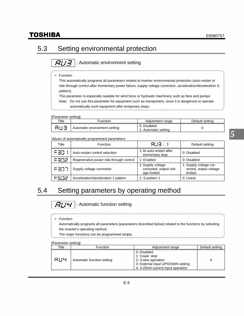
E6580757
E-5
5
5.3 Setting environmental protection
: Automatic environment setting
• FunctionThis automatically programs all parameters related to inverter environmental protection (auto-restart orride-through control after momentary power failure, supply voltage correction, acceleration/deceleration S-pattern).This parameter is especially suitable for wind force or hydraulic machinery such as fans and pumpsNote: Do not use this parameter for equipment such as transporters, since it is dangerous to operate
automatically such equipment after temporary stops.
[Parameter setting]Title Function Adjustment range Default setting
Automatic environment setting 0: Disabled1: Automatic setting 0
Values of automatically programmed parametersTitle Function Default setting
Auto-restart control selection 1: At auto-restart aftermomentary stop 0: Disabled
Regenerative power ride-through control 1: Enabled 0: Disabled
Supply voltage correction1: Supply voltage
corrected, output volt-age limited
1: Supply voltage cor-rected, output voltagelimited
Acceleration/deceleration 1 pattern 1: S-pattern 1 0: Linear
5.4 Setting parameters by operating method
: Automatic function setting
• FunctionAutomatically programs all parameters (parameters described below) related to the functions by selectingthe inverter's operating method.The major functions can be programmed simply.
[Parameter setting]Title Function Adjustment range Default setting
Automatic function setting
0: Disabled1: Coast stop2: 3-wire operation3: External input UP/DOWN setting4: 4-20mA current input operation
0

E6580757
E-6
5
Automatically programmed functions and parameter set valuesDefault setting 1: Coast stop 2: 3-wire opera-
tion3: External input
UP/DOWN set-ting
4: 4-20mA currentinput operation
2: Potentiometer 2: Potentiometer 2: Potentiometer 1: Operationpanel 0: Terminal board
1: Operationpanel 0: Terminal board 0: Terminal board 0: Terminal board 0: Terminal board
(F) 2: F 2: F 2: F 2: F 2: F
(R) 3: R 3: R 3: R 3: R 3: R
(RST) 10: RST 10: RST 10: RST 10: RST 10: RST
(S1) 6: SS1 6: SS1 6: SS1 41: UP 6: SS1
(S2) 7: SS2 7: SS2 7: SS2 42: DOWN 38: FCHG
(S3) 8: SS3 1: ST 49: HD 43: CLR 1: ST
(ST) 1: Always active0: Activated by
turning ST onactive
1: Always active 1: Always active0: Activated by
turning ST onactive
0: VIA/II 0: VIA/II 0: VIA/II 3: UP/DOWN 0: VIA/II
- - - - 20%
- - - - -
- - - - -
- - - - -
- - - 1 -
- - - 0.1Hz -
- - - 1 -
- - - 0.1Hz -
Disabled ( )
Input terminals and parameters are standards programmed at the factory.Coast stop ( )
Setting for coast stopping. ST (standby signal) is assigned to the S3 terminal and the operation is controlledby the on and off of the S3 terminal.
3-wire operation ( )
Can be operated by a momentary push-button. HD (operation holding) is assigned to the terminal S3. Aself-holding of operations is made in the inverter by connecting the stop switch (b-contact) to the S3 termi-nal and connecting the running switch (a-contact) to the F terminal or the R terminal.
External input UP/DOWN setting( )
Allows setting of frequency with the input from an external contact. Can be applied to changes of frequen-cies from several locations. UP (frequency up signal input from external contact) is assigned to the S1 ter-

E6580757
E-7
5
minal, and DOWN (frequency down signal input from external contact) are assigred to the S2 and CLR (fre-quency up/down clear signal input from external contact) are assigned to the S3 terminals respectively.Frequencies can be changed by input to the S1 and S2 terminals.
4-20mA current input operation( )
Used for setting frequencies with 4-20mA current input. Priority is given to current input and FCHG (fre-quency command forced switching) and ST (standby terminal) are assigned to the S2 and S3 terminals re-spectively. Remote/manual control (by different frequency commands) can be switched by input to the S2terminal. The S3 terminal can also be used for coast stop.
5.5 Selection of operation mode
: Command mode selection
: Frequency setting mode selection
• FunctionThese parameters are to program which command to the inverter (from operation panel or terminal board)will be given priority in running/stopping the operation and in frequency setting (internal potentiometer, op-eration panel or terminal board).
<Command mode selection>Title Function Adjustment range Default setting
Command mode selection 0: Terminal board1: Operation panel 1
[Setting value]
: Terminal boardoperation ON and OFF of an external signal Runs and stops operation.
: Operation paneloperation
Press the and keys on the operation panel to Run and stop a run.Performs the Run and stop of a run when the optional expansion panel is used.
* There are two types of function: the function that conforms to commands selected by , and the func-tion that conforms only to commands from the terminal board. See the table of input terminal function selectionin Chapter 11.
* When priority is given to commands from a linked computer or terminal board, they have priority over the set-ting of .
<Frequency setting mode selection>Title Function Adjustment range Default setting
Frequency setting mode selection0: Terminal board1: Operation panel2: Internal potentiometer
2

E6580757
E-8
5
[Setting values]
: Terminal board Frequency setting commands are entered by external signals. (VIA/VIB termi-nals: 0-10Vdc or II terminal: 4-20mAdc)
:Operationpanel
Press the key or the key on either the operation panel or the ex-pansion panel (optional) to set frequency.
:Internalpotentiometer
The internal potentiometer to the inverter is used for setting frequencies. Turningthe notches clockwise raises the frequency.
No matter what value the command mode selection and the frequency setting mode selection are set to the control input terminal functions described below are always in operative state.• Reset terminal (default setting: RST, valid only for tripping)• Standby terminal (when programmed by programmable input terminal functions).• External input trip stop terminal (when programmed by programmable input terminal functions)
To make changes in the command mode selection and the frequency setting mode selection ,first stop the inverter temporarily. (Can be changed while in operation when is set to .)
Preset-speed operation : Set to (Terminal board). : Valid in all setting values.
5.6 Meter setting and adjustment
: Meter selection
: Meter adjustment
• FunctionThe signal output from the FM terminal is an analog voltage signal.For the meter, use either a full-scale 0-1mAdc ammeter or full-scale 0-7.5Vdc (or 10Vdc) voltmeter.Note that the jumper pin JP302 can be set to switch to 0-20mA (4-20mA) current output. Adjust to 4-20mA with parameter (meter bias).

E6580757
E-9
5
Adjustment scale with meter adjustment parameterConnect meters as shown below.
Meter: frequency meter(default setting)
<Ammeter>
The reading of thefrequency meterwill fluctuate duringscale adjustment.
Make the maximum ammeter scale at least 150percent of the inverter's rated output current
Optional frequency meter: QS-60T
<Frequency meter>
The reading of thefrequency meterwill fluctuate duringscale adjustment.
Meter: ammeter( = 1)
[Connected meter selection parameters]Title Function Adjustment range Default setting
Meter selection
0: Output frequency1: Output current2: Set frequency3: For adjustment (current fixed at 100%)4: Inverter load factor5: Output power
0
Meter adjustment - -
ResolutionAll FM terminals have a maximum of 1/256
Example of 4-20mA programmed output (for details, see 6.15.10)
Set the if adjusting the bias.

E6580757
E-10
5
[Example of how to adjustment the FM terminal frequency meter]
* Use the meter's adjustment screw to pre-adjust zero-point.Key operated LED display Operation
- Displays the operation frequency. (When standard monitor display selec-tion is set to [operation frequency]Press the MON key to display the first basic parameter (automaticacceleration/deceleration) .
Press either the key or the key to select " ."
Press the ENTER key to display the operation frequency.
Press the key or the key to adjust the meter. The meter reading willchange at this time but be careful because there will be no change in theinverter's digital LED (monitor) indication.
The adjustment is complete. and the frequency are displayed alter-nately.The display returns to its original indications (displaying the operationfrequency). (When standard monitor display selection is set to [operation frequency].
Adjusting the meter in inverter stop stateIf, when adjusting the meter for output current, there are large fluctuations in data during adjustment, makingadjustment difficult, the meter can be adjusted in inverter stop state.When setting to for adjustment (100% fixed current), a signal of absolute values will be output(inverter's rated current = 100%). In this state, adjust the meter with the (Meter adjustment) parameter.After meter adjustment is ended, set to (output current).
5.7 Standard default setting
: Default setting
• FunctionAllows setting of all parameters to the standard default setting, etc. at one time.
Title Function Adjustment range Default setting
Standard setting mode selection
0 ∼ 2 : - (invalid)3: Default setting4: Trip clear5: Cumulative operation time clear6: Initialize inverter type information
0
[Hint]It's easier to make the adjustment ifyou push and hold for several seconds.

E6580757
E-11
5
This function will be displayed as during reading on the right. This previous setting is displayed.Ex.
cannot be set during the inverter operating. Always stop the inverter first and then program.
[Setting values]Default setting
Setting to will return all parameters to the standard values that were programmed at the factory. When 3 is programmed, will be displayed for a short time after setting and will then be erased
and displayed the original indication ( setup parameter). Trip history data will be cleared at this
time. For setting setup parameters, see 4.1.4.
Trip clear
Setting to initializes the past four sets of recorded error history data. (The parameter does not change.)
Cumulative operation time clear
Setting to allows the initial resetting of the cumulative operation time monitor (0 [zero] time).
Initialize inverter type information
Setting to clears the trips when an format error occurs. But if the displayed, callus.
5.8 Selecting forward and reverse runs (operation panelonly)
: Forward/reverse run selection
• FunctionProgram the direction of rotation when the running and stopping are made using the RUN key and STOPkey on the operation panel. Valid when (command mode) is set to 1 (operation panel).
Parameter settingTitle Function Adjustment range Default setting
Forward/reverse run selection 0: Forward run 1: Reverse run 0 Check the direction of rotation on the status monitor.
: Forward run : Reverse run ⇒ For monitoring, see 8.1.
When the F and R terminals are used for switching between forward and reverse rotation from the ter-minal board, the forward/reverse run selection is rendered invalid.Short across the F-CC terminals: forward rotation

E6580757
E-12
5
Short across the R-CC terminals: reverse rotation* Reverse rotation is valid if short across the F-CC terminals and R-CC terminals at the same time.
This function is valid only when is set to 1 (operation panel).
5.9 Maximum frequency
: Maximum frequency
• Function1) Programs the range of frequencies output by the inverter (maximum output values).2) This frequency is used as the reference for acceleration/deceleration time.
Frequency setting signal (%)
• This function determines themaximum value in line with theratings of the motor and load.
• Maximum frequency cannot beadjusted during operation. Toadjust, first stop the inverter.
WhenOutput frequency(Hz)
When
If is increased, adjust the upper limit frequency as necessary.
Parameter settingTitle Function Adjustment range Default setting
Maximum frequency 30.0 ∼ 400 (Hz) 80.0
5.10 Upper limit and lower limit frequencies
: Upper limit frequency
: Lower limit frequency
• FunctionPrograms the lower limit frequency that determines the lower limit of the output frequency and the upperlimit frequency that determines the upper limit of that frequency.

E6580757
E-13
5
Upper limitfrequencyOutput frequency (Hz)
Frequency setting signal
Lower-limitfrequency
The output frequencycannot be set at lessthan .
Frequencies that gohigher than willnot be output.
Output frequency (Hz)
Frequency setting signal
Parameter settingTitle Function Adjustment range Setting after setup
Upper limit frequency 0.5 ∼ (Hz) 50 or 60 *
Lower limit frequency 0.0 ∼ (Hz) 0.0* Setting value depending on the end of Type – form.
AN, WN : 60Hz, WP : 50Hz
5.11 Base frequency
: Base frequency 1
• FunctionSets the base frequency in conformance with load specifications or the motor's rated frequency.
Note:This is an important parameter that determines the constant torque control area.
Base frequency voltage
Out
put v
olta
ge [
V]
Output frequency (Hz)
Title Function Adjustment range Setting after setup
Base frequency 1 25 ∼ 400 (Hz) 50 or 60 *
* Setting value depending on the end of Type – form.AN, WN : 60Hz, WP : 50Hz

E6580757
E-14
5
5.12 Selecting control mode
: V/F control mode selection
• FunctionWith VF-S9, the V/F controls shown below can be selected
¹V/F constant¹Variable torque¹Automatic torque boost¹Sensorless vector control *1
¹Automatic energy-saving(*1) "Automatic torque boost " parameter can automatically set this parameter and auto-tuning at a
time.
Parameter settingTitle Function Adjustment range Default setting
V/F control mode selection
0: V/F constant1: Variable torque2: Automatic torque boost3: Sensorless vector control4: Automatic energy-saving
0
[Setting V/F control mode selection to 3 (sensorless vector control)]Key operated LED display Operation
Displays the operation frequency. (When standard monitor displayselection is set to 0 [operation frequency])Press the MON key to display the first basic parameter (automatic acceleration/deceleration).Press the key to change the parameter to (V/F control modeselection).Press the ENTER key to display the parameter setting. (Standarddefault setting: (V/F constant))Press the key to change the parameter to 3 (sensorless vectorcontrol).Press the ENTER key to save the changed parameter. and theparameter set value are displayed alternately.

E6580757
E-15
5
1) Constant torque characteristics (general method of use)Setting of V/F control mode selection to (V/F constant)
This is applied to loads with equipment like conveyors and cranes that require the same torque at lowspeeds as at rated speeds.
Base frequency voltage
Base frequency Output frequency (Hz)
Out
put v
olta
ge (
%)
To increase the torque further, increase the setting value of the manual torque boost .⇒ For more details, see 5.13.
2) Setting for fans and pumpsSetting of V/F control selection to (variable torque)
This is appropriate for load characteristics of such things as fans, pumps and blowers in which the torque inrelation to load rotation speed is proportional to its square.
Base frequency voltage
Base frequency Output frequency (Hz)
Out
put v
olta
ge (
%)

E6580757
E-16
5
3) Increasing starting torqueSetting V/F control selection to (automatic torque boost)
Detects load current in all speed ranges and automatically adjusts voltage output (torque boost) from inverter.This gives steady torque for stable runs.
Base frequency voltage
Base frequency Output frequency (Hz)
Out
put v
olta
ge (%
)
Automaticallyadjusts the amountof torque boost.
Note: This control system can oscillate and destabilize runs depending on the load. If that shouldhappen, set V/F control mode selection to (V/F constant) and increase torque manually.
Motor constant must be setIf the motor you are using is a 4P Toshiba standard motor and if it has the same capacity as the inverter,there is basically no need to set the motor constant.There are two procedures for setting the motor constant.1) The motor constant can be set automatically (auto-tuning). Program the extended parameter
to . ⇒ For details, see selection 2 in 6.13.2) Each motor constant can be set individually. ⇒ For details, see selection 3 in 6.13.
4) Sensorless vector control--increasing starting torque and achieving high-precisionoperation.
Setting of V/F control mode selection to (Sensorless vector control)Using sensorless vector control with a Toshiba standard motor will provide the highest torque at the lowestspeed ranges. The effects obtained through the use of sensorless vector control are described below.(1) Provides large starting torque.(2) Effective when stable operation is required to move smoothly up from the lowest speeds.(3) Effective in elimination of load fluctuations caused by motor slippage.
Motor constant must be setIf the motor you are using is a 4P Toshiba standard motor and if it has the same capacity as the inverter,there is basically no need to set the motor constant.There are three procedures for setting motor constants.
1) The sensorless vector control and motor constants (auto-tuning) can be set at a time.Set the basic parameter to . ⇒ For details, see 1 in 5.2.
2) The motor constant can be automatically set (auto-tuning).Set the extended parameter to . ⇒ For details, see selection 2 in 6.13.

E6580757
E-17
5
3) Each motor constant can be set individually. ⇒ For details, see selection 3 in 6.13.
5) Energy-savingSetting V/F control mode selection to (automatic energy-saving)
Energy can be saved in all speed areas by detecting load current and flowing the optimum current that fitsthe load.
Motor constant must be setThe motor you are using is a 4P Toshiba standard motor and if it has the same capacity as the inverter, thereis basically no need to set the motor constant.There are two procedures for setting the motor constant.1) The motor constant can be set automatically (auto-tuning). Set the extended parameter to .
⇒ For details, see selection 2 in 6.13.2) Each motor constant can be set individually. ⇒ For details, see selection 3 in 6.13.
6) Precautions on vector control1) The sensorless vector control exerts its characteristics effectively in frequency areas below the base fre-
quency ( ). The same characteristics will not be obtained in areas above the base frequency.2) Set the base frequency to anywhere from 40 to 120Hz during sensorless vector control ( ).3) Use a general purpose squirrel-cage motor with a capacity that is the same as the inverter's rated capac-
ity or one rank below.The minimum applicable motor capacity is 0.1kW.
4) Use a motor that has 2~8 P.5) Always operate the motor in single operation (one inverter to one motor). Sensorless vector control can-
not be used when one inverter is operated with more than one motor.6) The maximum length of wires between the inverter and motor is 30 meters. If the wires are longer than
30 meters, set standard auto-tuning with the wires connected to improve low-speed torque during sen-sorless vector control.However the effects of voltage drop cause motor-generated torque in the vicinity of rated frequency to besomewhat lower.
7) Connecting a reactor or surge voltage suppression filter between the inverter and the motor may reducemotor-generated torque. Setting auto-tuning may also cause a trip ( ) rendering sensorless vectorcontrol unusable.

E6580757
E-18
5
5.13 Manual torque boost - increasing torque at lowspeeds
: Torque boost 1
• FunctionIf torque is inadequate at low speeds, increase torque by raising the torque boost rate with this parame-ter.
Base frequency voltage
Base frequency Output frequency (Hz)
Out
put v
olta
ge [V
]/(%
)
[Parameters]Title Function Adjustment range Default setting
Torque boost 1 0 ∼ 30 (%) According to model(See section 11)
Valid for the standard default setting, = 0 (V/F constant) and 1 (variable torque).Note 1: The optimum value is programmed for each inverter capacity. Be careful not to increase the torque boost
rate too much because it could cause an overcurrent trip at startup. If you are going to change the setvalues, keep them within ±2% of the standard default values.
5.14 Setting the electronic thermal : Electronic thermal protection characteristic selection
: Motor electronic thermal protection level 1
• FunctionSelects the electronic thermal protection characteristics that fit with the ratings and characteristics of themotor. This is the same parameter as the extended parameter . The set values will be the sameno matter which one is changed.

E6580757
E-19
5
Parameter settingTitle Function Adjustment range Default setting
Settingvalue
Overloadprotection
Overloadstall
0 ¹ ×1 ¹ ¹2 × ×3
Standardmotor
× ¹4 ¹ ×5 ¹ ¹6 × ×
Electronic thermal protectioncharacteristics selection
7
VF motor(specialmotor)
× ¹
0
( )Motor electronic thermal pro-tection level 1 10 ∼ 100 (%) 100
¹ : valid, × : invalid
1) Setting the electronic thermal protection characteristics selection andmotor electronic thermal protection level 1 The electronic thermal protection characteristics selection is used to enable or disable the motoroverload trip function ( ) and the overload stall function.While the inverter overload trip ( ) will be in constant detect operation, the motor overload trip ( )can be selected using the parameter .
Explanation of termsOverload stall: When the inverter detects an overload, this function automatically lowers the output
frequency before the motor overload trip is activated. The soft stall functionallows the drive to run with balanced load current frequency without a trip. This is anoptimum function for equipment such as fans, pumps and blowers with variabletorque characteristics that the load current decreases as the operating speed de-creases.
Note: Do not use the overload stall function with loads having constant torque characteristics (such asconveyor belts in which load current is fixed with no relation to speed).
[Using standard motors (other than motors intended for use with inverters)]When a motor is used in the lower frequency range than the rated frequency, that will decrease the coolingeffects for the motor. This speeds up the start of overload detection operations when a standard motor isused in order to prevent overheating.

E6580757
E-20
5
Setting of electronic thermal protection characteristics selection Setting value Overload protection Overload stall
¹ ×
¹ ¹
× ×
× ¹
¹ : valid, × : invalid
Setting of motor electronic thermal protection level 1 If the capacity of the motor is smaller than the capacity of the inverter, or the rated current of the motoris smaller than the rated current of the inverter, adjust the electronic thermal protection level 1 sothat it fits the motor's rated current.
Output current reduction factor[%]/[A]
Output frequency (Hz)
Note: The motor overload protection start level is fixed at 30Hz.
[Example of setting: When the VFS9-2007PM is running with a 0.4kW motor having 2A rated current ]Key operated LED display Operation
Displays the operation frequency (perform during stop).(When standard monitor display selection is set to [operation frequency])Press the MON key to display the first basic parameter (automatic acceleration/deceleration).Press either the key or the key to change the parameter to .Press the ENTER key to display the parameter setting. (Standarddefault setting: 100%)Press the key to change the parameter to
(= motor rated current/inverter output rated current x 100 =2.0/4.8 x 100).
(When PWM carrier frequency is set to 12kHz.)Press the ENTER key to save the changed parameter. and the parameter set value are displayed alternately.

E6580757
E-21
5
[Using a VF motor (motor for use with inverter)]
Setting selection of electronic thermal protection characteristicsSetting value Overload protection Overload stall
¹ ×
¹ ¹
× ×
× ¹
¹ : valid, × : invalidA VF motor (a motor for use with an inverter) can be used in lower frequency ranges than the general-purpose motor, but if that frequency is extremely low, the effects of cooling on the motor will deteriorate.
Setting the motor electronic thermal protection level 1If the capacity of the motor being used is smaller than the capacity of the inverter, or the rated current ofthe motor is smaller than the rated current of the inverter, adjust the electronic thermal protection level 1
so that it fits the motor's rated current.* If the indications are in percentages (%), then 100% equals the inverter's rated output current (A).
Output current reduction factor[%]/[A]
Output frequency (Hz)Setting of motor overload protection start level
× 0.6
× 1.0

E6580757
E-22
5
2) Inverter over load characteristicsSet to protect the inverter unit. Cannot be changed or turned off by parameter setting.If the inverter overload trip function ( ) is activated frequently, this can be improved by adjusting thestall operation level downward or increasing the acceleration time or deceleration time .
Inverter overloadTime [s]
100%: inverter rated output current
Output current [%]
* To protect the inverter, overload trip may activate in a short period of time when outputcurrent reaches 150% or higher.
Inverter overload protection characteristics
5.15 Preset-speed operation (speeds in 15 steps)
∼ : Preset-speed operation frequencies 1~7
~ : Same as Sr1 ~ Sr7
∼ : Preset-speed operation frequencies 8~15
• FunctionA maximum of 15 speed steps can be selected just by switching an external contact signal. Multi-speedfrequencies can be programmed anywhere from the lower limit frequency to the upper limit frequency .
[Setting method]1) Run/stop
The starting and stopping control is done from the terminal board.Title Function Adjustment range Setting
Command mode selection 0: Terminal board1: Operation panel 1
Note: If speed commands (analog signal or digital input) are switched in line with preset-speed operations, selectthe terminal board using the frequency setting mode selection . ⇒ See 3) or 5.5

E6580757
E-23
5
2) Preset-speed frequency settingSet the speed (frequency) of the number of steps necessary.
Setting from speed 1 to speed 7Title Function Adjustment range Default setting
∼or
~
Preset-speed operation frequencies1~7 ∼ (Hz) 0.0
Setting from speed 8 to speed 15Title Function Adjustment range Default setting
∼ Preset-speed frequencies 8~15 ∼ (Hz) 0.0
Examples of preset-speed contact input signals (JP301 set to sink logic)O: ON -: OFF (Speed commands other than preset-speed commands are valid when all are OFF)
Preset-speedTerminal
1 2 3 4 5 6 7 8 9 10 11 12 13 14 15S1-CC ¹ - ¹ - ¹ - ¹ - ¹ - ¹ - ¹ - ¹
S2-CC - ¹ ¹ - - ¹ ¹ - - ¹ ¹ - - ¹ ¹
S3-CC - - - ¹ ¹ ¹ ¹ - - - - ¹ ¹ ¹ ¹
RST-CC - - - - - - - ¹ ¹ ¹ ¹ ¹ ¹ ¹ ¹
Terminal functions are as follows.Terminal S1............. Input terminal function selection 4 (S1) =6 (SS1)Terminal S2............. Input terminal function selection 5 (S2) =7 (SS2)Terminal S3............. Input terminal function selection 6 (S3) =8 (SS3)Terminal RST.......... Input terminal function selection 3 (RST) =9 (SS4)
SS4 is not allocated to standard default setting. Use the input terminal function selection to allocate SS4an idle terminal. In the above example the RST terminal is used for SS4.
Example of a connection diagram (JP301 set to sink logic)
CC
RST
S2
S3
S1
F (Forward run)
R (Reverse run)
Forward
Preset-speed 1
Reverse
Preset-speed 4
Preset-speed 3
Preset-speed 2
VF-S9
CC
S1
S2
RST
S3

E6580757
E-24
5
3) Using other speed commands with preset-speed command
Command mode selection 0 : Terminal board 1 : Operation panel
Frequency settingmode selection
0 : Terminalboard
Analog signal
1 : Operationpanel 2 : Potentiometer
0 : Terminalboard
Analog signal
1 : Operationpanel 2 : Potentiometer
Entered Preset - speed commandValid Note)
Analog signalValid
Operation panelCommand Valid
PotentiometerValidPreset - speed
command Notentered
Analog signalValid
Operation panelCommand Valid
PotentiometerValid
Note) The preset-speed command is always given priority when other speed commands are input at thesame time.
Below is an example of 7-step speed operation with standard default setting.
Output frequency [Hz]
Time[s]
S1-CC
ST-CC
F-CC
S2-CC
S3-CC
Example of 7-step speed operation
(The inverter doesn’t accept Preset - speed command.)

E6580757
F-1
6
6. Extended parametersExtended parameters are provided for sophisticated operation, fine adjustment and other special purposes. Modify pa-rameter settings as required. See Section 11, Table of extended parameters.
6.1 Input/output parameters
6.1.1 Low-speed signal
: Low-speed signal output frequency
• FunctionWhen the output frequency exceeds the setting of this parameter, an ON signal will be generated. Thissignal can be used as an electromagnetic brake excitation/release signal. Relay output (250Vac-2A (cos φ = 1), 30Vdc-1A, 250Vac -1A (cos φ = 0.4) at RY-RC or FLA-FLC-
FLB terminals (Default setting: RY-RC). Open-collector output (24Vdc-50mA [maximum]) can also be set at OUT terminal.
[Parameter setting]Title Function Adjustment range Default setting
Low-speed signal output frequency 0.0 ∼ (Hz) 0.0
Set frequency
Low-speed signal outputRY-RC terminals (Default setting)P24-OUT terminalsFLA-FLC-FLB terminalsLow-speed signal output: Inverted
Time [sec]
Output frequency[Hz]

E6580757
F-2
6
[Connection diagram for sink logic] [Incase of relay]
P24
OUTRy
Ry
RC
RY
• Output terminal settingOutput of the low-speed signal (ON signal) between the RY and RC terminals is the factory default set-ting of the output terminal selection parameter. This setting must be changed to invert the polarity ofthe signal.[Parameter setting]
Title Function Adjustment range Setting
Output terminal selection 1(RC-RY)
0 ∼ 29(see section 11)
4 (ON signal)or
5 (OFF signal)
If the signal output from OUT terminal, set to the value.
6.1.2 Output of designated frequency reach signal
: Speed reach detection band
• FunctionWhen the output frequency becomes equal to the designated frequency the setting of this parameter, an ON or OFF signal is generated.
Parameter setting of designated frequency and detection bandTitle Function Adjustment range Default setting
Speed reach detection band 0.0 ∼ (Hz) 2.5
Parameter setting of output terminal selectionTitle Function Adjustment range Setting
Output terminalselection 2 (OUT)
0 ∼ 29(See section 11)
6: RCH (Designated frequency - ON signal),or
7: RCH (Designated frequency - OFF signal)Note: Select the parameter to specify RY-RC terminal output, or the parameter to specify
FLA-FLC-FLB terminal output.

E6580757
F-3
6
ONOFF
ONOFF
0
Output frequency [Hz]
Designated frequency attainment signalP24-OUT (Default setting)RY-RCFLA-FLC-FLB
Speed attainment set frequency: Inverted
Designated frequency
Designated frequency +
Designated frequency −
Time [s]
6.1.3 Output of set frequency speed reach signal
: Speed reach setting frequency
: Speed reach detection band
• FunctionWhen the output frequency becomes equal to the setting of the parameter ± the setting ofthe parameter, an ON or OFF signal is generated.
Parameter setting of set frequency and detection bandTitle Function Adjustment range Default setting
Speed reach setting frequency 0.0 ∼ (Hz) 0.0
Speed reach detection band 0.0 ∼ (Hz) 2.5
Parameter setting of output terminal selectionTitle Function Adjustment range Setting
Output terminalselection 2 (OUT)
0 ∼ 29(See section 11)
6: RCH(Designated frequency - ON signal),
or7: RCH
(Designated frequency - OFF signal)Note: Select the parameter to specify RY-RC terminal output, or the parameter to specify
FLA-FLC-FLB terminal output.

E6580757
F-4
6
1) If the detection band value + the set frequency is less than the designated fre-quency
Set frequency speed reach detection signalRY-RCP24-OUTFLA/FLC/FLBSet frequency speed reach signal: Inverted
Output frequency [Hz]
Time [sec]
6.2 Input signal selection
6.2.1 Changing the standby signal function
: ST (standby) signal selection
• FunctionThe F103 parameter specifies standby function activation timing, depending on the particular status ofthe ST (standby) signal.1) Standby on only when ST is on (ST-CC on: Standby, ST-CC off: Gate off [Coast stop])2) Standby always on3) Synchronized with F/R (F/R-CC on: Forward/reverse run, F/R-CC off: Coast stop)4) Standby on only when ST is off (ST-CC off: Standby, ST-CC on: Gate off [Coast stop])
Parameter settingTitle Function Adjustment range Default setting
ST signal selection
0: Standby on when ST is on1: Standby always on2: Interlocked with F/R3: Standby on when ST is off
1

E6580757
F-5
6
1) Standby on when ST is on
F-CC
Motor speedCoast stop Use this setting if an ST (standby)
terminal is required.
* The ST terminal is not assignedas standard default setting.Assign the ST function to anidle input terminal by the inputterminal selection.
ST-CC
2) Standby always on (Default setting)The inverter enters a standby status, irrespective of the ST signal status. Motor rotation stops according tothe selected deceleration time at the set frequency.
3) Interlocked with F/R
F-CC
Motor speedCoast stop
Turning the operationsignal (F/R) off causesthe motor to coast to astop.
4) Standby on when ST is offInversion of item 1) above.
6.2.2 Setting the reset signal
: RST (reset) signal selection
• FunctionThe parameter specifies reset function activation timing, depending on the particular status ofthe RST (reset) signal.1) Standard setting (reset on when RST-CC on to off)2) Activated by turning RST off (reset on when RST-CC off to on)
• This parameter is available in the modifying input terminal functions ( ∼ ) = 10 (RST).• To reset the protective function on the parameter setting , do any of the following.
1. Turn off the power.2. Press the STOP key twice while the protection function is displayed.3. Turn on and off the error reset control input signal.

E6580757
F-6
6
Parameter settingTitle Function Adjustment range Default setting
RST signal selection
0: Standard setting(reset on when RST-CC on to off)
1: Activated by turning RST off(reset on when RST-CC off to on)
0
6.3 Terminal function selection
6.3.1 Keeping an input terminal function always active (ON)
: Always-active function selection
• FunctionThis parameter specifies an input terminal function that is always to be kept active (ON). (Only onefunction selectable)
Parameter settingTitle Function Adjustment range Default setting
Always-active function selection 0 ∼ 51 (See section 11) 0
6.3.2 Modifying input terminal functions
: Input terminal selection 1 (F)
: Input terminal selection 2 (R)
: Input terminal selection 3 (RST)
: Input terminal selection 4 (S1)
: Input terminal selection 5 (S2)
: Input terminal selection 6 (S3)
Use the above parameters to send signals from an external programmable controller to various control inputterminals to operate and/or set the inverter.The desired contact input terminal functions can be selected from 51 types. This gives system design flexi-bility.

E6580757
F-7
6
Setting of contact input terminal functionTerminalsymbol Title Function Adjustment range Default setting
- Always-active function selection 0 (Without assignedfunction)
F Input terminal selection 1 (F) 2 (Forward run)
R Input terminal selection 2 (R) 3 (Reverse run)
RST Input terminal selection 3 (RST) 10 (Reset)
S1 Input terminal selection 4 (S1) 6 (Preset-speed 1)
S2 Input terminal selection 5 (S2) 7 (Preset-speed 2)
S3 Input terminal selection 6 (S3)
0-51(See Section 11
table of input termi-nal functions)
8 (Preset-speed 3)
Note: The function that has been selected using (always-active function selection parameter) is al-ways activated.
Connection method1) A-contact input (Sink logic)
CC
Inverter
This function is activated when the inputterminal and CC (common) are short-circuited. Use this function to specifyforward/reverse run or a preset-speedoperation.
A-contact switchInput terminal
2) Connection with transistor output
Input terminal Operation can be controlled by connecting
the input and CC (common) terminals to theoutput (no-contacts switch) of theprogrammable controller. Use this functionto specify forward/reverse run or a preset-speed operation. Use a transistor thatoperates at 24Vdc/5mA.
Inverter Programmable controller
* Interface between programmable controller and inverterWhen operation is to be controlled using a programmable controller of the open-collector outputtype, if the programmable controller is turned off with the inverter on, the difference in control powerpotential will cause wrong signals to be sent to the inverter as shown in the diagram below. Be sureto provide an interlock so that the programmable controller cannot be turned off when the inverter ison.

E6580757
F-8
6
Fuse blowoutdetection circuit
External +24Vpower supply Inverter internal
+24V powersupply
Fuse
InverterProgrammable controller
3) Sink logic/source logic inputSink logic/source logic (input/output terminal logic) switching is possible.See Section 2.3 for further details.
Example of application ... Three-wire operation
F
S3
CC
START
STOPRun: Press START. contact-aStop: Press STOP. contact-b
[Parameter setting]Terminalsymbol Title Function Adjustment range Setting
F Input terminal selection 1 2 (Forward runningcommand)
S3 Input terminal selection 6
0-51(see Section 11) 49
(Operation holding)
ST signal selection 0-3 1(Stand by always on)
In case of three-wire operation, set to 1.

E6580757
F-9
6
6.3.3 Modifying output terminal functions
: Output terminal selection 1 (RY-RC)
: Output terminal selection 2 (OUT)
: Output terminal selection 3 (FLA/B/C)
Use the above parameters to send various signals from the inverter to external equipment.Up to 30 functions can be used by setting special parameters for the RY-RC, OUT, and FL (FLA, FLB, FLC)terminals on the control terminal board.
Examples of application
Function of RY-RC:Can be set using parameter .
Function of OUT:Can be set using parameter .
Function of FLA/B/C:Can be set using parameter .
FLA
FLC
RY
RC
P24
OUT
FL
RY
RY
FLB
Setting of output terminal functionTerminalsymbol Title Function Adjustment range Default setting
RY-RC Output terminal selection 1 4 (Low-speeddetection signal)
OUT Output terminal selection 2 6 (Designatedfrequency reach)
FL Output terminal selection 3
0∼ 29(see Section 11)
10(Failure FL)
Sink logic/source logic output (OUT)Sink logic/source logic (output terminal logic) switching is possible.See Section 2.3 for further details.

E6580757
F-10
6
6.4 Basic parameters 2
6.4.1 Switching motor characteristics via terminal input
: Base frequency 2
: Torque boost 2
: Motor electronic-thermal protection level 2
• FunctionUse the above parameters to switch the operation of two motors with a single inverter and to selectmotor V/F characteristics (two types) according to the particular needs or operation mode.
Note: The (V/F control mode selection) parameter is enabled only for motor 1. If motor 2 is se-lected, V/F control will be given constant torque characteristics.
Parameter settingTitle Function Adjustment range Default setting
Base frequency 2 25 ∼ 400 (Hz) 50 or 60
Torque boost 2 0.0 ∼ 30.0 (%) According to model(See section 11)
Motor electronic-thermal protection level 2 10 ∼ 100 (%) 100
*Setting value of F170 depending on the end of Type-form. AN, WN : 60Hz, WP : 50Hz
Setting of switching terminalsThe terminal for switching to motor 2 needs to be set, since this function is not assigned under the defaultsetting. Assign this function to an idle terminal.The parameters to be switched depend on the particular identification number of the input terminal selectionfunction.
Input terminal function number Parameters to be used or switched40:MCHG 39:THR2 5:AD2
OFF OFF OFF Parameters to be used , , , , , ,
OFF OFF ON Parameters to be switched → , → , →
OFF ON OFF Parameters to be switched → , → , → , →
OFF ON ON Parameters to be switched → , → , → , → → , → , →
ON - - Parameters to be switched → , → , → , → → , → , →

E6580757
F-11
6
6.5 Frequency priority selection
6.5.1 Using a frequency command according to the particularsituation
: Frequency setting mode selection
: Frequency priority selection
• FunctionUse the above parameters to select the command to be used for frequency setting, and to assignpriority to one of the two types of input frequency reference signals.
• Combination of the and parameters• Switching via terminal board input
Parameter settingTitle Function Adjustment range Default setting
Frequency setting mode selection0: Terminal board1: Operation panel2: Internal potentiometer
2
Parameter settingTitle Function Adjustment range Default setting
Frequency priority selection
0: VIA/II, VIB1: VIB, VIA/II2: External switching
(FCHG enabled)3: External contact UP/DOWN4: External contact UP/DOWN
(Setting retained even if thepower is turned off)
5: VIA/II + VIB
0
The VIA terminal and II terminal cannot be used at the same time.
1) Automatic frequency switching 1Frequency priority selection parameter (Default setting)
= 0: Terminal board is selected.First priority is assigned to analog input terminals VIA/II, and second priority to analog input terminals VIB.When the input to VIA/II with first priority becomes null, control will be switched automatically to VIB with sec-ond priority.
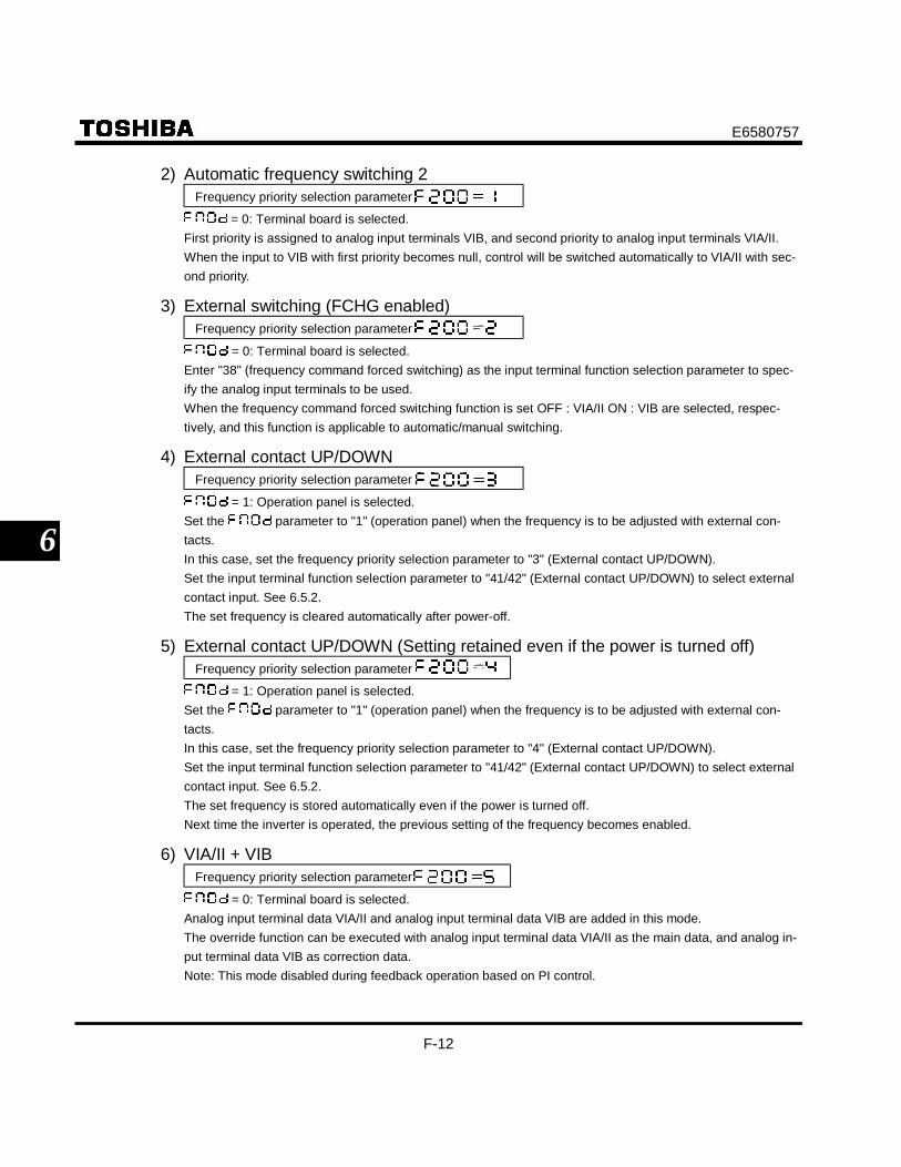
E6580757
F-12
6
2) Automatic frequency switching 2Frequency priority selection parameter
= 0: Terminal board is selected.First priority is assigned to analog input terminals VIB, and second priority to analog input terminals VIA/II.When the input to VIB with first priority becomes null, control will be switched automatically to VIA/II with sec-ond priority.
3) External switching (FCHG enabled)Frequency priority selection parameter
= 0: Terminal board is selected.Enter "38" (frequency command forced switching) as the input terminal function selection parameter to spec-ify the analog input terminals to be used.When the frequency command forced switching function is set OFF : VIA/II ON : VIB are selected, respec-tively, and this function is applicable to automatic/manual switching.
4) External contact UP/DOWNFrequency priority selection parameter
= 1: Operation panel is selected.Set the parameter to "1" (operation panel) when the frequency is to be adjusted with external con-tacts.In this case, set the frequency priority selection parameter to "3" (External contact UP/DOWN).Set the input terminal function selection parameter to "41/42" (External contact UP/DOWN) to select externalcontact input. See 6.5.2.The set frequency is cleared automatically after power-off.
5) External contact UP/DOWN (Setting retained even if the power is turned off)Frequency priority selection parameter
= 1: Operation panel is selected.Set the parameter to "1" (operation panel) when the frequency is to be adjusted with external con-tacts.In this case, set the frequency priority selection parameter to "4" (External contact UP/DOWN).Set the input terminal function selection parameter to "41/42" (External contact UP/DOWN) to select externalcontact input. See 6.5.2.The set frequency is stored automatically even if the power is turned off.Next time the inverter is operated, the previous setting of the frequency becomes enabled.
6) VIA/II + VIBFrequency priority selection parameter
= 0: Terminal board is selected.Analog input terminal data VIA/II and analog input terminal data VIB are added in this mode.The override function can be executed with analog input terminal data VIA/II as the main data, and analog in-put terminal data VIB as correction data.Note: This mode disabled during feedback operation based on PI control.

E6580757
F-13
6
6.5.2 Setting frequency command characteristics
: VIA/II input point 1 setting
: VIA/II input point 1 frequency
: VIA/II input point 2 setting
: VIA/II input point 2 frequency
: VIB input point 1 setting (Frequency UP response time)
: VIB input point 1 frequency (Frequency UP step width)
: VIB input point 2 setting (Frequency DOWN response time)
: VIB input point 2 frequency (Frequency DOWN step width)
• FunctionThese parameters adjust the output frequency according to the externally applied analog signal(0-10V dc voltage, 4-20mA dc current) and the entered command for setting an external contactfrequency.
Parameter settingTitle Function Adjustment range Default setting
VIA/II input point 1 setting 0 ∼ 100 (%) 0VIA/II input point 1 frequency 0.0 ∼ 400.0 (Hz) 0.0VIA/II input point 2 setting 0 ∼ 100 (%) 100VIA/II input point 2 frequency 0.0 ∼ 400.0 (Hz) 50 or 60 *1VIB input point 1 setting 0 ∼ 100 (%) 0Frequency UP response time 0 ∼ 100 (1: 0.1 s) 0VIB input point 1 frequency 0.0 ∼ 400.0 (Hz) 0.0Frequency UP step width 0.0 ∼ 400.0 0VIB input point 2 setting 0 ∼ 100 (%) 100Frequency DOWN response time 0 ∼ 100 (1: 0.1 s) 100VIB input point 2 frequency 0.0 ∼ 400.0 (Hz) 50 or 60 *1Frequency DOWN step width 0.0 ∼ 400.0 50 or 60 *1
Note1) Setting value of and depending on the end of Type form. AN, WN : 60Hz, WP: 50Hz.Note2) ~ can be used as UP/DOWN function depend on the setting.Note3) Don't set the same value between point 1 and point 2.
If set the same value, the is displayed.

E6580757
F-14
6
1) 0-10Vdc voltage input adjustment (VIA, VIB)
• The output frequency withrespect to the voltage input isadjusted according to theselected reference point.
• Gradient and bias can be seteasily.
VIA, VIB terminals
voltage signal
50 or 60 (Hz)
2) 4-20mAdc current input adjustment (II)II terminal
current signal
• The output frequency withrespect to the current input isadjusted according to theselected reference point.
• Gradient and bias can be seteasily.
• Set to " " to create acurrent input from 0 to 20mA.
50 or 60 (Hz)
3) Setting frequency via external contact input(only when = , = or )
Adjustment with continuous signals (Parameter-setting example 1)Set parameters as follows to adjust the output frequency up or down in proportion to the frequency ad-justment signal input time:
Panel frequency incremental gradient = setting timePanel frequency decremental gradient = setting time

E6580757
F-15
6
Set parameters as follows to adjust the output frequency up or down almost in synchronization with theadjustment by the panel frequency command:
= = 1[ (or ) / ] ≤ ( setting time)[ (or ) / ] ≤ ( setting time)
<<Sample sequence diagram 1: Adjustment with continuous signals>>
RUN command
Incrementing(UP) signal
Decrementing(DOWN) signal
Upper limit frequency
Set frequencyclearing signal
Gradient:
Lower limit frequency
Frequency
Gradient:
The dotted line denotes the output frequency obtained by combining the slowdown speed and the panelfrequency adjustment speed.
0Hz
Adjustment with pulse signals (Parameter-setting example 2)Set parameters as follows to adjust the frequency in steps of one pulse:
, > Pulse ON time > 32msec , = Frequency obtained with each pulse
* If signal input time less than setting , is not responded. 12ms or more of clearingsignal is allowed.
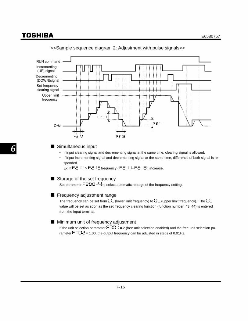
E6580757
F-16
6
<<Sample sequence diagram 2: Adjustment with pulse signals>>
OHZ
RUN command
Incrementing (UP) signal
Decrementing (DOWN)signal
Set frequency clearing signal
Upper limit frequency
Simultaneous input• If input clearing signal and decrementing signal at the same time, clearing signal is allowed.• If input incrementing signal and decrementing signal at the same time, difference of both signal is re-
sponded.Ex. If > frequency ( - ) increase.
Storage of the set frequencySet parameter = to select automatic storage of the frequency setting.
Frequency adjustment rangeThe frequency can be set from (lower limit frequency) to (upper limit frequency). The value will be set as soon as the set frequency clearing function (function number: 43, 44) is enteredfrom the input terminal.
Minimum unit of frequency adjustmentIf the unit selection parameter = 2 (free unit selection enabled) and the free unit selection pa-rameter = 1.00, the output frequency can be adjusted in steps of 0.01Hz.

E6580757
F-17
6
6.6 Operation frequency
6.6.1 Starting frequency
: Starting frequency setting
• FunctionThe frequency set with the parameter is put out immediately on completion of frequency set-ting.Use the parameter when a delay in response of starting torque according to the accelera-tion/deceleration time is probably affecting operation. Setting the starting frequency to a value from 0.5to 2Hz (maximum: 5Hz) is recommended. The occurrence of an overcurrent can be suppressed bysetting this frequency below the rated slippage of the motor.
[Parameter setting]Title Function Adjustment range Default setting
Starting frequency setting 0.5 ∼ 10.0 (Hz) 0.5
Output frequency [Hz]
Starting frequency setting
Time [sec]

E6580757
F-18
6
6.6.2 Run/stop control with frequency setting signals : Operation starting frequency
: Operation starting frequency hysterisis
• FunctionThe Run/stop of operation can be controlled simply with frequency setting signals.
[Parameter setting]Title Function Adjustment range Default setting
Operation starting frequency 0.0 ∼ (Hz) 0.0
Operation starting frequency hysterisis 0.0 ∼ (Hz) 0.0
Output frequency [Hz]
Frequency command value
The inverter begins accelerating afterthe frequency setting signal hasreached point B. Deceleration beginswhen the frequency setting signaldecreases below point A.
6.7 DC braking
6.7.1 DC braking
: DC braking starting frequency
: DC braking current
: DC braking time
• FunctionA large braking torque can be obtained by applying a direct current to the motor. These parametersset the direct current to be applied to the motor, the application time and the starting frequency.

E6580757
F-19
6
[Parameter setting]Title Function Adjustment range Default setting
DC braking starting frequency 0.0 ∼ (Hz) 0.0
DC braking current 0.0 ∼ 100 (%) 30.0
DC braking time 0.0 ∼ 20.0 (sec) 1.0
DC braking starting frequency
Output frequency [Hz]
Set frequency
Output current [A]
DC braking
Time [sec]
DC braking current
DC braking time
Operation signal (F-CC)
Note: During DC braking, the overload protection sensitivity of the inverter increases. The DC braking cur-rent may be adjusted automatically to prevent tripping.
6.8 Jog run mode
: Jog run frequency
: Jog run stopping pattern
• FunctionUse the jog run parameters to operate the motor in jog mode. Input of a jog run signal generates a jogrun frequency output at once, irrespective of the designated acceleration time.
The motor can be operated in jog mode while the jog run setting terminals are connected (RST-CC ON).(Setting to .)

E6580757
F-20
6
[Parameter setting]Title Function Adjustment range Default setting
Jog run frequency 0.0 ∼ 20.0 (Hz) 0.0
Jog run stopping pattern0: Slowdown stop1: Coast stop2: DC braking
0
<Examples of jog run>RST-CC (JOG) ON + F-CC ON: Forward jog run
RST-CC (JOG) ON + R-CC ON: Reverse jog run
( Normal operation frequency signal input + F-CC ON: Forward run )
( Normal operation frequency signal input + R-CC ON: Reverse run )
Output frequency [Hz]
Set frequency
Forward
ST-CC
Normal operation frequencysetting signal input
ReverseForward
Forward
F-CC
R-CC
RST-CC
• The jog run setting terminal (RST-CC) is enabled when the operation frequency is below the jog run fre-quency. This connection does not function at an operation frequency exceeding the jog run frequency.
• The motor can be operated in jog mode while the jog run setting terminals are connected (RST-CC ON).• Jog run has priority, even when a new operation command is given during operation.• Even for or , an emergency DC braking becomes enabled when setting parameter to
.
[Setting of jog run setting terminal (RST-CC)]Assign control terminal RST ([4: reset signal] in default setting) as the jog run setting terminal.
Title Function Adjustment range Default setting
Input terminal selection (RST) 0 ∼ 514
(jog run settingterminal)
Note: During the jog run mode, there is LOW (low speed detection signal) output but no RCH (designatedfrequency reach signal) output, and PID control does not work.

E6580757
F-21
6
6.9 Jump frequency - jumping resonant frequencies
: Jump frequency 1
: Jumping width 1
: Jump frequency 2
: Jumping width 2
: Jump frequency 3
: Jumping width 3
• FunctionResonance due to the natural frequency of the mechanical system can be avoided by jumping the reso-nant frequency during operation. During jumping, hysterisis characteristics with respect to the jump fre-quency are given to the motor.
Output frequency [Hz]
Jump frequency 1
Jumping width 3
Frequency setting signal
Jump frequency 3
Jump frequency 2 Jumping width 2
Jumping width 1
[Parameter setting]Title Function Adjustment range Setting
Jump frequency 1 ∼ (Hz) 0.0
Jumping width 1 0.0 ∼ 30.0 (Hz) 0.0
Jump frequency 2 ∼ (Hz) 0.0
Jumping width 2 0.0 ∼ 30.0 (Hz) 0.0
Jump frequency 3 ∼ (Hz) 0.0
Jumping width 3 0.0 ∼ 30.0 (Hz) 0.0
Do not set the jump parameters, If multiple jump frequency setting width overlap. During acceleration or deceleration, the jumping function is disabled for the operation frequency.

E6580757
F-22
6
6.10 Preset-speed operation frequency 8 to 15
∼ : Preset-speed operation frequency 8 to 15
See Section 5.15 for details.
6.11 PWM carrier frequency
: PWM carrier frequency
: Random mode
• Function1) The F300 parameter allows the tone of the magnetic noise from the motor to be changed by switching
the PWM carrier frequency. This parameter is also effective in preventing the motor from resonatingwith its load machine or its fan cover.
2) In addition, the F300 parameter reduces the electromagnetic noise generated by the inverter. Reducethe carrier frequency to reduce electromagnetic noise. Note: Although the electromagnetic noise levelis reduced, the magnetic noise of the motor is increased.
3) The random mode reduces motor electromagnetic noise by changing the pattern of the reduced carrierfrequency. (Allowable operation frequency: 80Hz max.)
[Parameter setting]Title Function Adjustment range Default setting
PWM carrier frequency 2.0 ∼ 16.5 (kHz) * 12.0
Random mode 0: Disabled, 1: Enabled 0* Load reduction will be required if the PWM carrier frequency is modified for each applicable motor model.
Load reduction ratios required[200V Class]
Carrier frequencyVFS9-VFS9S- 4kHz or less 12kHz 15kHz 16.5kHz
2002PL/M 1.5A 1.5A 1.5A 1.5A2004PL/M 3.3A 3.3A 3.1A 3.0A2007PL/M 4.8A 4.4A 4.2A 3.9A2015PL/M 7.8A 7.5A 7.2A 7.1A2022PL/M 11.0A 10.0A 9.1A 8.7A2037PM 17.5A 16.5A 15.0A 14.3A2055PL 27.5A 25.0A 25.0A 25.0A2075PL 33.0A 33.0A 29.8A 28.2A2110PM 54.0A 49.0A 49.0A 49.0A2150PM 66.0A 60.0A 54.0A 51.0A

E6580757
F-23
6
[400V Class]480V or less More than 480V
Carrier frequency Carrier frequencyVFS9- 4kHz or less 12kHz 15kHz 16.5kHz 4kHz or less 12kHz 15kHz 16.5kHz4007PL 2.3A 2.1A 2.1A 2.1A 2.1A 1.9A 1.9A 1.9A4015PL 4.1A 3.7A 3.3A 3.1A 3.8A 3.4A 3.1A 3.0A4022PL 5.5A 5.0A 4.5A 4.3A 5.1A 4.6A 4.2A 4.0A4037PL 9.5A 8.6A 7.5A 7.0A 8.7A 7.9A 6.9A 6.4A4055PL 14.3A 13.0A 13.0A 13.0A 13.2A 12.0A 12.0A 12.0A4075PL 17.0A 17.0A 14.8A 13.7A 15.6A 14.2A 12.4A 12.0A4110PL 27.7A 25.0A 25.0A 24.7A 25.5A 23.0A 23.0A 23.0A4150PL 33.0A 30.0A 26.4A 24.9A 30.4A 27.6A 24.3A 23.0A
• Note:Default setting of PWM carrier frequency is 12kHz, but rated output current of rating label display at4kHz.
6.12 Trip-less intensification
6.12.1 Auto-restart (Restart during coasting)
: Auto-restart control selection
Caution
Mandatory
• Stand clear of motors and mechanical equipmentIf the motor stops due to a momentary power failure, the equipment will start suddenly when power isrestored. This could result in unexpected injury.
• Attach warnings about sudden restart after a momentary power failure on inverters, motors and equip-ment to prevent accidents in advance.
• FunctionThe F301 parameter detects the rotating speed and rotational direction of the motor during coastingin the event of momentary power failure, and then after power has been restored, restarts the motorsmoothly (motor speed search function). This parameter also allows commercial power operation tobe switched to inverter operation without stopping the motor.During operation, " " is displayed.

E6580757
F-24
6
Title Function Adjustment range Default setting
Auto-restart controlselection
0: Disabled1: At auto-restart after momentary stop2: When turning ST-CC on or off3: At auto-restart or when turning ST-CC on or off4: Motion of DC braking at start-up (at auto-
restart after momentary stop)5: Motion of DC braking at start-up (when turning
ST-CC on or off)6: Motion of DC braking at start-up (at auto-
restart or when turning ST-CC on or off)
0
* If the motor is restarted in retry mode, this function will operate, regardless of the setting of this parameter.
1) Auto-restart after momentary power failure (Auto-restart function)
Input voltage
Motor speed
F-CC
Setting to , ( ): This function operates after power has been restored following detection of anundervoltage by the main circuits and control power.
2) Restarting motor during coasting (Motor speed search function)Motor speed
F-CC
ST-CC
Setting to , ( ): This function operates after the ST-CC terminal connection has been openedfirst and then connected again.
3) DC braking during restartIf this parameter is set to either " ", " ", or " ", DC braking specified by parameter , or will be conducted during the restart of the motor.This function is effective when the motor is under a momentary power failure or coasting status and is re-versing for some external reason.

E6580757
F-25
6
Application!!• A waiting time of 200 to 1,000msec is preset to allow the residual voltage in the motor to decrease
to a certain level during restart. For this reason, the start-up takes more time than usual.• Use this function when operating a system with one motor connected to one inverter. This function
may not operate properly in a system configuration with multiple motors connected to one inverter.Application to a crane or hoistThe crane or hoist may have its load moved downward during the above waiting time from input ofthe operation starting command to the restart of the motor. To apply the inverter to such machines,therefore, set the auto-restart control mode selection parameter to "0" (Disabled), and avoid usingthe retry function. If retry function is enabled the load could move downward causing damage andor injury.
6.12.2 Regenerative power ride-through control
: Regenerative power ride-through control
• FunctionRegenerative power ride-through control continues the operation of the motor by utilizing motor re-generative energy in the event of momentary power failure.
[Parameter setting]Title Function Adjustment range Default setting
Regenerative power ride-through control 0: Disabled, 1: Enabled 0
Note: Even when this parameter is set, the particular load conditions may cause the motor to coast. In thiscase, use the auto-restart function along with this parameter function.
[When power is interrupted] The time for which the operation of the
motor can be continued depends on themachine inertia and load conditions. Beforeusing this function, therefore, performverification tests.
Use with the retry function allows the motorto be restarted automatically without beingbrought to an abnormal stop.
The operation continuing time is about100ms when regenerative power ride-through control is enabled ( = 1).
Input voltage
Motor speed
Approx. 100ms
[If momentary power failure occurs]Input voltage
Motor speed
100ms (maximum)

E6580757
F-26
6
6.12.3 Retry function
: Retry selection (Selecting the number of times the motor is to berestarted automatically)
Warning
Mandatory
• Do not go near the motor in alarm-stop status when the retry function is selected.The motor may suddenly restart, which could result in injury.
• Take measures for safety, e.g. attach a cover to the motor, to prevent accidents if the motor suddenly re-starts.
• FunctionThis parameter resets the inverter automatically when the inverter gives an alarm. During the retrymode, the motor speed search function operates automatically as required and thus allows smoothmotor restarting.
[Parameter setting]Title Function Adjustment range Default setting
Retry selection 0: None, 1 ∼ 10 times 0
The likely causes of tripping and the corresponding retry processes are listed below.Cause of tripping Retry process Canceling conditions
Momentary powerfailureOvercurrentOvervoltageOverload
Up to 10 times in succession1st retry: About 1 sec after tripping2nd retry: About 2 sec after tripping3rd retry: About 3 sec after tripping
…10th retry: About 10 sec after tripping
The retry function will be canceled atonce if tripping is caused by an unusualevent other than: momentary power fail-ure, overcurrent, overvoltage or overload.This function will also be canceled if re-trying is not successful within the speci-fied number of times.
The retry function is disabled in the following unusual events:• : Arm overcurrent at start-up • : Main unit RAM fault• : Overcurrent on the load side at start-up • : Main unit ROM fault• : Output phase failure • : CPU fault trip• : External thermal trip • : Remote control error• : Overtorque trip • : EE PROM fault• : Small-current operation trip • : Auto-tuning error• : External trip stop• : Undervoltage trip (main circuit) • : Ground fault trip• : Input phase failure • : Inverter type error
Protective operation detection relay signals (FLA, FLB, FLC terminal signals) are not sent during use ofthe retry function.
A virtual cooling time is provided for overload tripping ( , , ). In this case, the retry func-tion operates after the virtual cooling time and retry time.
In the event of over voltage tripping ( ∼ ), re-tripping may result unless the DC voltage de-
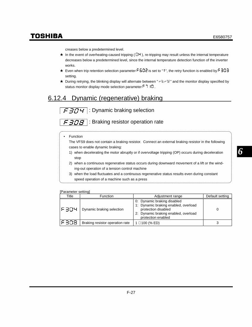
E6580757
F-27
6
creases below a predetermined level. In the event of overheating-caused tripping ( ), re-tripping may result unless the internal temperature
decreases below a predetermined level, since the internal temperature detection function of the inverterworks.
Even when trip retention selection parameter is set to " ", the retry function is enabled by setting.
During retrying, the blinking display will alternate between " " and the monitor display specified bystatus monitor display mode selection parameter .
6.12.4 Dynamic (regenerative) braking
: Dynamic braking selection
: Braking resistor operation rate
• FunctionThe VFS9 does not contain a braking resistor. Connect an external braking resistor in the followingcases to enable dynamic braking:1) when decelerating the motor abruptly or if overvoltage tripping (OP) occurs during deceleration
stop2) when a continuous regenerative status occurs during downward movement of a lift or the wind-
ing-out operation of a tension control machine3) when the load fluctuates and a continuous regenerative status results even during constant
speed operation of a machine such as a press
[Parameter setting]Title Function Adjustment range Default setting
Dynamic braking selection
0: Dynamic braking disabled1: Dynamic braking enabled, overload
protection disabled2: Dynamic braking enabled, overload
protection enabled
0
Braking resistor operation rate 1 ∼ 100 (% ED) 3

E6580757
F-28
6
1) Connecting an external braking resistor (optional)Separate-type optional resistor (with thermal fuse)
IMR/L1
PBRExternal braking resistor (optional)
Three-phasemain circuitsPower supply
Motor
Connecting thermal relays and an external braking resistor
Without control power
External braking resistor(optional)
Motor
Forward run/stop
Reverse run/stop
Inverter
Power supply
Three-phase main circuits Power supply
FuseSurge suppressor
Step-down transformer
PBR
S/L2
T/L3
U/T1
V/T2
W/T3
PAMCCB
Inverter
PB
MC
MCMCCB
TC
FLB F
W/T3
V/T2
U/T1
K
CC
G
R/L1
PA PB
TH-R
R/L2
R/L3
FLC
FLA
IM
2 : 1
[Parameter setting]Title Function Setting
Dynamic braking selection 2
Braking resistor operation rate Any value
Overvoltage limit operation 1
Optional dynamic braking resistor capacities are selected for an operation rate of 3%ED. To connect a dynamic braking resistor, set the overvoltage limit operation parameter to
"1" (Disabled). To use this inverter in applications that create a continuously regenerative status (such as down-
ward movement of a lift, a press or a tension control machine), or in applications that requireslowdown stopping of a machine with a significant load inertial moment, increase the dynamicbraking resistor capacity according to the operation rate required.
To connect an external dynamic braking resistor, select one with a resultant resistance valuegreater than the minimum allowable resistance value. Be sure to set the appropriate operationrate in to ensure overload protection.
To use a braking resistor without a thermal fuse or to use a braking resistor in mode" " of , connect thermal relays as shown in the diagram above, to make an operation cir-cuit for stopping operation.

E6580757
F-29
6
2) Setting the braking resistor operation rateCalculate the braking resistor operation rate as follows:
Braking resistoroperating time
Operation rate: Tr/T * 100 (%ED)
1-cycle operation time T
3) Optional dynamic braking resistors (Optional braking resistors for higher frequen-cies of regenerative braking are also available)Optional dynamic braking resistors are listed below. All these resistors are 3%ED in operation rate.
Braking resistor/Braking unitInverter model Model number RatingVFS9S-2002PL ∼ 2007PLVFS9-2002PM ∼ 2007PM PBR-2007 120W- 200Ω
VFS9S-2015PL ∼ 2022PLVFS9-2015PM ∼ 2022PM PBR-2022 120W- 75Ω
VFS9-2037PM PBR-2037 120W- 40ΩVFS9-2055PL PBR3-2055 120W- 40Ω × 2P (240W- 20Ω)VFS9-2075PL PBR3-2075 220W- 30Ω × 2P (440W- 15Ω)VFS9-2110PM PBR3-2110 220W- 30Ω × 3P (660W- 10Ω)VFS9-2150PM PBR3-2150 220W- 30Ω × 4P (880W- 7.5Ω)
VFS9-4007PL ∼ 4022PL PBR-2007 120W- 200ΩVFS9-4037PL PBR-4037 120W-160ΩVFS9-4055PL PBR3-4055 120W-160Ω × 2P (240W- 80Ω)VFS9-4075PL PBR3-4075 220W-120Ω × 2P (440W- 60Ω)VFS9-4110PL PBR3-4110 220W-120Ω × 3P (660W- 40Ω)VFS9-4150PL PBR3-4150 220W-120Ω × 4P (880W- 30Ω)
Note: The data in parentheses above refer to the resultant resistance capacities (watts) and resultant resis-tance values (ohms) of standard braking resistors.

E6580757
F-30
6
4) Minimum resistances of connectable braking resistorsThe minimum allowable resistance values of the externally connectable braking resistors are listed in the ta-ble below.Do not connect braking resistors with smaller resultant resistances than the listed minimum allowable resis-tance values.
200V class 400V classInverter ratedoutput capacity
(kW)Resistance of
standard optionMinimum allowable
resistanceResistance of
standard optionMinimum allowable
resistance0.2 200Ω 63Ω - -0.4 200Ω 63Ω - -
0.75 200Ω 42Ω 200Ω 99Ω1.5 75Ω 30Ω 200Ω 99Ω2.2 75Ω 30Ω 200Ω 73Ω3.7 40Ω 24Ω 160Ω 73Ω5.5 20Ω 10Ω 80Ω 44Ω7.5 15Ω 10Ω 60Ω 44Ω11 10Ω 7Ω 40Ω 22Ω15 7.5Ω 7Ω 30Ω 22Ω
6.12.5 Avoiding overvoltage tripping
: Overvoltage limit operation
• FunctionThis parameter keeps the output frequency constant or increases the frequency to prevent overvolt-age tripping due to increases in DC voltage during deceleration or constant-speed operation. Thedeceleration time during overvoltage limit operation may increase above the designated time.
DC voltage
Overvoltage limiting level
Outputfrequency
Overvoltage limiting level
[Parameter setting]Title Function Adjustment range Default setting
Overvoltage limit operation 0: Enabled1: Prohibited 0

E6580757
F-31
6
6.12.6 Output voltage adjustment/Supply voltage correction
: Output voltage adjustment (Base frequency voltage)
: Supply voltage correction
• FunctionOutput voltage adjustment (Base frequency voltage)The parameter adjusts the voltage corresponding to the base frequency 1 so that novoltage exceeding the set value is put out. (This function is enabled only when isset to either "0", "1", or "2".)Supply voltage correctionThe parameter maintains a constant V/F ratio, even when the input voltage decreases. Thetorque during low-speed operation is prevented from decreasing.
Supply voltage correction .............. Maintains a constant V/F ratio, even when the input voltage fluctuates.Output voltage adjustment ............. Limits the voltage at frequencies exceeding the base frequency. Applied
when operating a special motor with low induced voltage.
[Parameter setting]Title Function Adjustment range Default setting
Output voltage adjustment(Base frequency voltage) 0 ∼ 250 (V), 0 ∼ 500 (V) 200V/400V
Supply voltage correction
0: Supply voltage uncorrected,output voltage limited
1: Supply voltage corrected,output voltage limited
2: Supply voltage corrected (off during slow-down), output voltage limited
3: Supply voltage uncorrected,output voltage unlimited
4: Supply voltage corrected,output voltage unlimited
5: Supply voltage corrected (off during decel-eration), output voltage unlimited
1
If is set to "0" or "3", the output voltage will change in proportion to the input voltage. Even if the base frequency voltage ( parameter) is set above the input voltage, the output voltage
will not exceed the input voltage. The rate of voltage to frequency can be adjusted according to the rated motor capacity. For example,
setting to " " or " " prevents the output voltage from increasing, even if the input voltagechanges when operation frequency exceeds the base frequency.

E6580757
F-32
6
[0: Supply voltage uncorrected,output voltage limited]
Out
put v
olta
ge[V
]
Input voltage
Input voltage
Low
High
Output frequency
* The above applies when V/F control modeselection parameter is set to "0" or "1".
the output voltage can beprevented from exceeding theinput voltage.Rated voltage
Rated voltage×
1
Out
put v
olta
ge[V
]
Input voltage
Low
High
Output frequency
[1: Supply voltage corrected,output voltage limited]
[3: Supply voltage uncorrected,output voltage unlimited]
Out
put v
olta
ge[V
]
Input voltage
Input voltage
Low
High
Output frequency
* The above applies when V/F control modeselection parameter is set to "0" or "1".
the output voltage can beprevented from exceedingthe input voltage.Rated voltage
1
Rated voltage ×
[4: Supply voltage corrected,output voltage unlimited]
Out
put v
olta
ge[V
]
Input voltage
Low
High
Output frequency* Even if is set for an output voltage lower than the
input voltage, the output voltage will exceed the voltageadjusted by when the output frequency is higherthan the base frequency 1 .
The settings to " " and " " [supply voltage corrected (off during deceleration)] mean the same op-eration as those to " " and " ", respectively, except during deceleration. These settings prevent overvolt-age during deceleration, while minimizing decreases in low-speed operating torque due to changes in volt-age.

E6580757
F-33
6
6.12.7 Conducting PI control
: Proportional/integral control (PI control)
: Proportional gain
: Integral gain
• FunctionThese parameters provide various types of process control, such as maintaining constant air quan-tity, flow rates and pressures, by input of feedback signals from the detector.
[Parameter setting]Title Function Adjustment range Default setting
PI control 0: Disabled1: Enabled 0
Proportional gain 0.01 ∼ 100.0 0.30
Integral gain 0.01 ∼ 100.0 0.20
1) External connection
(1) Potentiometersetting
Feedback signals (1) DC: 4-20mA (2) DC: 0-10V
(2) Panel input setting
(3) Internal preset-speed setting
(4) External analogsetting
DC : 0~10V
Pressuretransmitter
R/L1S/L2
T/L3
U/T1
V/T2
W/T3
VIB
VIA
II
CC
M
P

E6580757
F-34
6
2) Types of PI control interfacesProcess quantity input data (frequency) and feedback input data can be combined as follows for the PI con-trol of the VF-S9:Process quantity input data (frequency setting) Feedback input dataSetting method Frequency setting mode
(1) Internal potentiometer setting
(2) Panel input setting
(3) Internal preset-speed setting(4) External analog setting
VIB (DC: 0-10V)
External analog input(1)II(DC:4 ∼ 20mA)(2)VIA(DC:0 ∼ 10V)
Note: When PI control is selected ( = "1"), frequency priority selection ( ) is disabled. In thiscase, therefore, since II or VIA is reserved for feedback signal input only, frequency setting by switchingto VIB cannot be executed.
3) Setting PI controlSet " " in the extended parameter (PI control).(1) Set parameters (acceleration time) and (deceleration time) to their minimum values (0.1
sec).(2) To limit the output frequency, set parameters (upper limit frequency) and (lower limit fre-
quency). If process quantities are set from the operation panel, however, the process quantity settingrange will be limited by the settings of and .
4) Adjusting the PI control gain levelAdjust the PI control gain level according to the process quantities, the feedback signals and the object to becontrolled.The following parameters are provided for gain adjustment:Parameter Setting range Default setting (P-gain) 0.01 ∼ 100.0 0.30
(I-gain) 0.01 ∼ 100.0 0.20
(P-gain adjustment parameter)This parameter adjusts the proportional gain level during PI control. A correction value proportional tothe particular deviation (the difference between the set frequency and the feedback value) is obtainedby multiplying this deviation by the parameter setting.A larger P-gain adjustment value gives faster response. Too large an adjustment value, however, re-sults in an unstable event such as hunting.
Slow response
Process quantity setting value
Time
Fast response

E6580757
F-35
6
(I-gain adjustment parameter)This parameter adjusts the integral gain level during PI control. Any deviations remaining unremovedduring proportional action are cleared to zero (residual deviation offset function).A larger I-gain adjustment value reduces residual deviations. Too large an adjustment value, however,results in an unstable event such as hunting.
Process quantity setting value
Time
Residual deviation
5) Adjusting analog command voltagesTo use external analog setting (VIB) or feedback input (II/VIA), perform voltage-scaling adjustments as re-quired. See Section 6.5.2 for further details.If the feedback input data is too small, voltage-scaling adjustment data can also be used for gain adjustment.
Example of VIB terminal setting Example of VIA terminal setting Example of II terminal setting
(50 or 60Hz) (50 or 60Hz) (50 or 60Hz)

E6580757
F-36
6
6.13 Setting motor constants
: Auto-tuning
: Slip frequency
: Motor primary constant
: Motor secondary constant
: Motor excitation constant
: Magnification of load inertial moment
: Rated capacity ratio of motor to inverter
To use vector control, automatic torque boost and automatic energy-saving, motor constant setting (motor tuning)is required. The following three methods are available to set motor constants (for automatic torque boosting,however, two methods are available):1) Using the automatic torque boost ( ) for setting the V/F control mode selection
( ) and auto-tuning ( ) at the same time2) Setting the V/F control mode selection ( ) and auto-tuning ( ) independently3) Combining the V/F control mode selection ( ) and manual tuningSensorless vector control may not operate properly if the motor capacity differs from the applicable rated capacityof the inverter by more than two grades.
[Selection 1: Setting by automatic torque boost]This is the easiest of the available methods. It conducts vector control and auto-tuning at the same time.
Set the automatic torque boost parameter ( ) to " "(Sensorless vector control + auto-tuning).See Section 5.2 for details of the setting method.
[Selection 2: Setting sensorless vector control and auto-tuning independently]This method sets sensorless vector control or automatic torque boost, and auto-tuning independently.Specify the control mode in the V/F control mode selection parameter "( )" and then set auto-tuning.
Set the auto-tuning parameter ( ) to " ".

E6580757
F-37
6
[Parameter setting]Title Function Adjustment range Default setting
Auto-tuning0: Auto-tuning disabled (Use of internal parameters)1: Application of individual settings of ∼2: Auto tuning enabled (returns to "1" after auto-tuning)
0
Set to " ".Set to " " if the motor capacity is one size smaller than the applicable rated capacity of the inverter.
Precautions on auto-tuning(1) Conduct auto-tuning only after the motor has been connected and operation completely stopped.
If auto-tuning is conducted immediately after operation stops, the presence of a residual voltagemay result in abnormal tuning.
(2) Voltage is applied to the motor during tuning even though it barely rotates.(3) Tuning is usually completed within three seconds. If it is aborted, the motor will trip with the dis-
play of " " and no constants will be set for that motor.(4) High-speed motors, high-slip motors or other special motors cannot be auto-tuned. For these
motors, perform manual tuning using Selection 3 described below.(5) Provide cranes and hoists with sufficient circuit protection such as mechanical braking. Without
sufficient circuit protection, the resulting insufficient motor torque during tuning could create a riskof machine stalling/falling.
(6) If auto-tuning is impossible or an " " auto-tuning error is displayed, perform manual tuningwith Selection 3.
[Selection 3: Setting vector control and manual tuning independently]If an " " tuning error is displayed during auto-tuning or when vector control characteristics are to beimproved, independent motor constants can be set.
Title Function Adjustment range Default setting
Auto-tuning
0: Auto-tuning disabled (Use of internal pa-rameters)
1: Application of individual settings of ∼
2: Auto-tuning enabled (returns to "1" afterauto-tuning)
0
Slip frequency 0.0 ∼ 10.0 (Hz) *
Motor primary constant 0 ∼ 255 *
Motor secondary constant 0 ∼ 255 *
Motor excitation constant 0 ∼ 255 *Magnification of load inertiamoment 0 ∼ 200 (time) 0
Rated capacity ratio of motorto inverter
0: Same capacity as inverter1: One size smaller than inverter 0
* The default settings of the above parameters vary with capacity. See section 11.

E6580757
F-38
6
Setting procedureAdjust the following parameters:
: Select " " to set the motor constant independently using the ∼ parameters. : Set the slip frequency for the motor. A higher slip frequency reduces motor slipping correspond-
ingly. (The slip frequency can be set on the basis of test records of the motor.) : Adjust the primary resistive component of the motor. Decreases in torque due to a possible volt-
age drop during low-speed operation can be suppressed by setting a large value in this parameter.(Perform adjustments according to the actual operation.)
: Adjust the secondary component of the motor. This parameter is enabled only when isset to " ". A larger adjustment value gives more slip correction. (Perform adjustments accordingto the actual operation.)
: Set the excitation inductance for the motor. A larger inductance creates a smaller no-load current.(Perform adjustments according to the actual operation.)
: Set a load inertia moment with a multiple of the motor inertia moment. A transient response canbe adjusted. A larger adjustment value reduces inertial overshoot, and thus prevents the occur-rence of an overcurrent and an overvoltage, correspondingly.
: Set "1" if the rated capacity of the motor is one size smaller than that of the inverter.* Sensorless vector control may not operate properly if the motor capacity differs from the appli-
cable rated capacity of the inverter by more than two grades.

E6580757
F-39
6
6.14 Acceleration/deceleration patterns andacceleration/deceleration 2
: Acceleration time 1
: Deceleration time 1
: Acceleration time 2
: Deceleration time 2
: Acceleration/deceleration 1 pattern
: Acceleration/deceleration 2 pattern
: Acceleration/deceleration pattern selection (1 or 2)
: Acceleration/deceleration 1 and 2 switching frequency
• FunctionThese parameters allow selection of the appropriate acceleration/deceleration pattern according to theparticular needs.Switching is also possible to the acceleration/deceleration pattern 2 using parameters, frequencies andexternal terminals.
Title Function Adjustment range Default settingAcceleration time 1 0.1 ∼ 3600 (s) 10.0
Deceleration time 1 0.1 ∼ 3600 (s) 10.0
Acceleration time 2 0.1 ∼ 3600 (s) 10.0
Deceleration time 2 0.1 ∼ 3600 (s) 10.0
Acceleration/deceleration 1 pattern 0: Linear, 1: S-pattern 1,2: S-pattern 2 0
Acceleration/deceleration 2 pattern 0: Linear, 1: S-pattern 1,2: S-pattern 2 0
Acceleration/deceleration pattern se-lection (1 or 2)
0: Acceleration/deceleration 1 ,1: Acceleration/deceleration 2 0
Acceleration/deceleration 1 and 2switching frequency 0 ∼ (Hz) 0.0

E6580757
F-40
6
Acceleration/deceleration patterns1) Linear acceleration/deceleration
A general acceleration/ deceleration pat-tern. This pattern can usually be used.
2) S-pattern acceleration/deceleration 1Select this pattern to accelerate/deceleratethe motor rapidly to a high-speed regionwith an output frequency of 60Hz or moreor to minimize the shocks applied duringacceleration/deceleration. This pattern issuitable for pneumatic transport machines.
3) S-pattern acceleration/deceleration 2Select this pattern to obtain slow accelera-tion in a demagnetizing region with a smallmotor acceleration torque. This pattern issuitable for high-speed spindle operation.
Output frequency [Hz]
Time [sec]
Maximumfrequency
Output frequency [Hz]
Time [sec]
Maximumfrequency
Set frequency
Actual acceleration time
Base frequency
Output frequency [Hz]
Time [sec]
MaximumfrequencySet frequency
Actual acceleration time

E6580757
F-41
6
Switching to acceleration/deceleration1) Selection using parameters
Output frequency [Hz]
Time [sec]
Acceleration/deceleration time 1 is initially set as the default. Acceleration/deceleration time 2 can beselected by changing the setting of the parameter.
2) Switching by frequencies - Switching the acceleration/deceleration time automatically at the frequencysetting of .
Output frequency [Hz]
Time [sec]
Set frequency
(1) (2) (3) (4)
(1) Acceleration at the gradientcorresponding to accelerationtime
(2) Acceleration at the gradientcorresponding to accelerationtime
(3) Deceleration at the gradientcorresponding to decelerationtime
(4) Deceleration at the gradientcorresponding to decelerationtime

E6580757
F-42
6
3) Switching using external terminals - Switching the acceleration/deceleration time via external termi-nals
Output frequency [Hz]
Time [sec]
(1) Acceleration at the gradientcorresponding to accelerationtime
(2) Acceleration at the gradientcorresponding to accelerationtime
(3) Deceleration at the gradientcorresponding to decelerationtime
(4) Deceleration at the gradientcorresponding to decelerationtime
(1) (2) (3) (4)
AD2 switching
In this case, set " " to 0 (terminal board).A switching signal for the acceleration/deceleration 2 is not set as the default.Assign function number 5 ( ) to an idle terminal by specifying the input terminal function selectionparameter.
6.15 Protection functions
6.15.1 Setting motor electronic thermal protection
: Motor electronic thermal protection level 1
• FunctionThis parameter allows selection of the appropriate electronic thermal protection characteristics ac-cording to the particular rating and characteristics of the motor.The " " parameter and extended parameter have the same function. Modification ofeither parameter means that the same value is set for both parameters.
Parameter settingTitle Function Adjustment range Default setting
( )Motor electronic thermal protectionlevel 1 10 ∼ 100 (%) 100

E6580757
F-43
6
6.15.2 Setting current stall
: Stall prevention level
• FunctionThis parameter reduces the output frequency by activating a current stall prevention function againsta current exceeding the -specified level.
Parameter settingTitle Function Adjustment range Default setting
Stall prevention level 10 ∼ 199 (%), 200: Disabled 150
[Display during an alarm status]During an alarm status (that is, when there is a current flow in excess of the stall prevention level),the output frequency changes. At the same time, to the left of this value, " " is displayed flashing onand off.
Example of display
6.15.3 Inverter trip retention
: Inverter trip retention selection
• FunctionIf the inverter trips, this parameter will retain the corresponding trip information. Trip information thathas thus been stored into memory can be displayed, even after power has been reset.
[Parameter setting]Title Function Adjustment range Default setting
Inverter trip retention selection 0: Not retained1: Retained 0
Up to four sets of latest trip information displayed in status monitor mode can be stored into memory. When power is turned back on, trip data in the status monitor mode (such as trip current and voltage) will
not be stored.
Panel (terminal) reset
Inverter tripped
Error information reset Normal operation
Power reset Power turned back on: Error displayed FL deactivated
Inverter tripped again: Error displayed FL activated
Only when the cause of theerror or other errors has notyet been removed

E6580757
F-44
6
6.15.4 External input trip stop mode selection
: External input trip stop mode selection
: Emergency DC braking time
• FunctionThese parameters set the method of stopping the inverter in external trip stop mode. When theinverter is stopped, the trip detection function (" " display) and the FL relay are activated. If is set to " " (Emergency DC braking), also set (DC braking current) and (Emergency DC braking time).
1) External trip stop via terminalsThe external trip stop function can be executed via the a-contact. Proceed as follows to assign an externalstopping terminal and select the stopping method:
Input terminal
CC
a-contact
[Parameter setting]Title Function Adjustment range Default setting
External input trip stop mode selection0: Coast stop1: Slowdown stop2: Emergency DC braking
0
Emergency DC braking time 0.0 ∼ 20.0 (s) 1.0
DC braking current 0∼ 100 (%) 30
(Example of terminal assignment): Assigning the trip stop function to the RST terminalTitle Function Adjustment range Setting
Input terminal selection (RST) 0 ∼ 51 11(External trip stop)
Notes:1) Emergency stopping via the specified terminal is possible, even during panel operation.2) If is set to "2" (Emergency DC braking) and DC braking is not required for normal stopping, set
the DC braking time ( ) to 0.0 (sec).

E6580757
F-45
6
2) Emergency stopping from the operation panelEmergency stopping from the operation panel is possible by pressing the STOP key on the panel twice whilethe inverter is not in the panel control mode.
(1) Press the STOP key ............................." " will blink.(2) Press the STOP key once again...........Operation will come to a trip stop in accordance with the setting
of the parameter. After this, " " will be displayed and afailure detection signal generated (FL relay deactivated).
6.15.5 Output phase failure detection
: Output phase failure detection mode selection
• FunctionThis parameter detects inverter output Phase failure. If the Phase failure status persists for one sec-ond or more, the tripping function and the FL relay will be activated. At the same time, the trip infor-mation will also be displayed.Set to " " to control the opening of the inverter connection to the motor and connectingcommercial power to the motor.Detection errors may occur for special motors such as high-speed motors.
(Disabled)................................ No tripping (FL relay deactivated).
(Enabled during operation)................................ Phase failure detection is enabled during operation. The inverter will trip if the
Phase failure status persists for one second or more. (FL relay activated.) (Enabled; Disabled during auto-restart)
................................ This function, however, is disabled during auto-restart after momentary power fail-ure. When phase failure detect decrease the output voltage, and restart.
Title Function Adjustment range Default setting
Output phase failure detection modeselection
0: Disabled1: Enabled (during operation)2: Enabled (Disabled during auto-restart)
0

E6580757
F-46
6
6.15.6 Input phase failure detection
: Input phase failure detection mode selection
• FunctionThis parameter detects inverter input Phase failure. If the abnormal voltage status of main circuit ca-pacitor persists for few minutes or more, the tripping function and the FL relay will be activated. Atthe same time, the trip information will also displayed.If the power capacity is larger than the inverter capacity (more than 200kVA or more than 10 times),detection errors may occur. If this actually happens, install an AC or DC reactor.
(Disabled) ...... No tripping (FL relay deactivated). (Enabled)....... Phase failure detection is enabled during operation. The inverter will trip if the
abnormal voltage status of main circuit capacitor persists for ten minutes ormore. (FL relay activated.)
Title Function Adjustment range Default settingInput phase failure detection modeselection
0: Disabled,1: Enabled 1
6.15.7 Control mode for small current
: Small current trip selection
: Small current (trip/alarm) detection current
: Small current (trip/alarm) detection time
• FunctionThe parameter allows the inverter to be tripped if a current smaller than the -specified value flows for more than the -specified time. When tripping is se-lected, enter the detection time to tripping. Trip information is displayed as “ ”.
(OFF)...... No tripping (FL relay deactivated).A small current alarm can be put out by setting the output terminal function selectionparameter.
(ON)........ The inverter is tripped (FL relay activated) only after a small current has been de-tected for more than the -specified time during operation.

E6580757
F-47
6
Title Function Adjustment range Default setting
Small current trip selection 0: Disabled1: Enabled 0
Small current (trip/alarm) detection current 0 ∼ 100 (%) 0
Small current (trip/alarm) detection time 0 ∼ 255 (s) 0
6.15.8 Over-torque trip
: Over-torque trip selection
: Over-torque (trip/alarm) level
: Over-torque (trip/alarm) detection time
: Over-torque (trip/alarm) level hysterisis
• FunctionUse the parameter to trip the inverter if a torque current exceeding the -specifiedlevel flows for more than the -specified time. Trip information is displayed as " ".
(No trip) ...... No tripping (FL relay deactivated).An overtorque alarm can be put out to the output terminal by setting the outputterminal function selection parameter.
(Trip) .......... The inverter is tripped (FL relay activated) only after a torque current exceedingthe -specified level has been detected for more than the -specified time.
Title Function Adjustment range Default setting
Over-torque trip selection 0: Disabled1: Enabled 0
Over-torque (trip/alarm) level 0 ∼ 250 (%) 150
Over-torque (trip/alarm) detection time 0.00 ∼ 10.0 (s) 0.5
Over-torque (trip alarm) level hysterisis 0 ∼ 100 (%) 10

E6580757
F-48
6
1) Output terminal function : 12 (OT) Over–torque detection (No trip)
Over-torquedetection signal
Torque current(%)
Time(s)
Less than
OFF OFFON
-
When setting to (Trip), trip after over-torque detection time setting of .
2) Output terminal function : 20 (POT) Over-torque detection pre-alarm (No trip)
Over-torque detectionpre-alarm signal
Torque current(%)
Time(s)
OFF OFFON
× 0.7
ON
× 0.7 -

E6580757
F-49
6
6.15.9 Undervoltage trip
: Undervoltage trip selection
• FunctionThis parameter is used for selecting the control mode when an undervoltage is detected. Trip infor-mation is displayed as “ “.
(Disabled).......The inverter is stopped. However, it is not tripped (FL relay deactivated).The inverter is stopped when the voltage does not exceed 70% or less of itsrating.
(Enabled) .......The inverter is stopped. It is also tripped (FL relay activated), only after detec-tion of a voltage not exceeding 70% or less of its rating.
(Disabled).......Control is continued even at 60% of the rated voltage.The inverter stop (FL relay deactivated), only after detection of a voltage not ex-ceeding 45% of its rating.An input AC reactor must be used. See 10.4.
Title Function Adjustment range Default setting
Undervoltage trip selection
0: Disabled1: Enabled (Trip at 70% or less)2: Disabled (Stop(not trip) at 45% or less,
optional)
0
6.15.10 4-20mA dc calibration
: Meter bias
• FunctionOutput signals from FM terminals are analog voltage signals. Their standard setting range is from 0to 1mAdc or from 0 to 7.5Vdc.These standard setting ranges can be switched to 0-20mAdc by changing the position of the requiredjumper pin (JP302) in the inverter main unit. Calibration for 4-20mA dc output is possible by settingthis parameter.
Title Function Adjustment range Default setting
Meter bias 0 ∼ 50 (%) 0Note: Use the jumper pin (JP302) to select FMC (0-20mA dc (4-20mA dc)) output.

E6580757
F-50
6
Examples of setting
6.16 Operation panel parameter
6.16.1 Prohibition of change of parameter settings
: Prohibition of change of parameter settings
• FunctionThis parameter specifies whether parameter setting is changeable or not.
Setting methods : Permitted_____Modification of and during operation is prohibited (default setting).
Modification of , , , , , , , , during operation is also prohibited.
: Prohibited_____All parameter read/write operations are prohibited. : Permitted_____Modification of , during operation is enabled. Modification of ,
, , , , , , , during operation,however, is prohibited.

E6580757
F-51
6
[Parameter setting]Title Function Adjustment range Default setting
Prohibition of change ofparameter settings
0: Permitted( , cannot be modified duringoperation)
1: Prohibited2: Permitted
( , can be modified during op-eration)
0
Resetting methodOnly the parameter is designed so that its setting can be modified even if " " (prohibited) is se-lected.
6.16.2 Changing the display unit to A/V/min-1
: Unit selection
: Free unit selection
• FunctionThese parameters are used to change the unit of monitor display.
% ⇔ A (ampere)/V (volt)Frequency ⇔ Motor speed or load speed
Parameter settingTitle Function Adjustment range Default setting
Unit selection
0: No change1: % → A (ampere)/V (volt)2: Free unit selection enabled ( )3: % → A (ampere)/V (volt)
Free unit selection enabled ( )
0
Free unit selection 0.01 ∼ 200.0 1.00
An example of setting for changing voltage/current percentage display to V/A unitdisplaySet to either " " or " ".During the operation of the VFS9-2037PM (rated current: 17.5A) at the rated load (100% load), units are dis-played as follows:

E6580757
F-52
6
1) Display in percentage terms 2) Display in amperes/volts
Output current: Output current:
Input (DC) voltage: Input (DC) voltage:
(vale of changing to AC)
An example of setting for displaying the motor speed or load speedSet to either " " or " ".The value obtained by multiplying the displayed frequency by the -set value will be displayed as fol-lows:
Value displayed = Monitor-displayed or parameter-set frequency ×
1) Displaying the motor speedTo switch the display mode from 60Hz (default setting) to 1800min-1 (the rotating speed of the 4P mo-tor)
2) Displaying the speed of the loading unitTo switch the display mode from 60Hz (default setting) to 6m/min-1 (the speed of the conveyer)
Note: This parameter displays the inverter output frequency as the value obtained by multiplying it by apositive number. Even when the actual speed of the motor changes according to the particularchanges in load, the output frequency will always be displayed.

E6580757
F-53
6
* The converts the following parameter settings:• A display Current monitor display
Motor electronic thermal protection level 1/2 ( ),
DC braking currentStall prevention levelSmall current detection level
• V display Voltage monitor displayTorque boost 1/2 ,
• Free unit Frequency monitor displayFrequency-related parameters , , , , ∼ ,
∼ , , , , , , , , , , , , , , ∼ ,
6.16.3 Changing the status monitor display format : Standard monitor display selection
• FunctionThis parameter specifies display format while power is on.
Changing the display format while power is onWhen the power is on, the standard monitor mode displays the operation frequency (default setting) in theformat of " " or " ". This format can be changed to any other monitor display format by setting
. This new format, however, will not display an assigned prefix such as " " or " ".• Standard monitor mode ⇒ Standard monitor display selection ( )
Title Function Adjustment range Default setting
Standard monitor display se-lection
0: Operation frequency (Hz/Free unit)1: Output current (%/A)2: Frequency command (Hz/Free unit)3: Inverter rated current (A)4: Inverter overload factor (%)5: Output power (%)
0
E6580757
F-54
6
6.17 Communication function (Common serial)
: Data transfer speed
: Parity
: Inverter number
: Communication error trip time
Refer to the COMMUNICATIONS EQUIPMENT USER'S MANUAL for details.
• FunctionThe VFS9 Series allows a data communication network to be constructed for exchanging data betweena host computer or controller (referred to collectively as the computer) and the inverter by connecting anoptional RS232C or RS485 communication conversion unit.<Computer-linking functions>
The following functions are enabled by data communication between the computer and inverter(1) Monitoring inverter status (such as the output frequency, current, and voltage)(2) Sending RUN, STOP and other control commands to the inverter(3) Reading, editing and writing inverter parameter settings
<RS232C communication>Data can be exchanged between one computer and one inverter.
<RS485 communication>Data can be exchanged between the computer and a maximum of 64 inverters.
The following are available as common serial optional units:• RS232C communications conversion unit (Model: RS2001Z)
Communications cable (Model: CAB0011, 1m long; CAB0013, 3m long; or CAB0015, 5m long)• RS485 communication conversion unit with terminal board (Model: RS4001Z)
Communication cable (Model: CAB0011, 1m long; CAB0013, 3m long; or CAB0015, 5m long)Note 1.: Limit the distance between the common serial optional units and the inverter to 5m.
2.: Set Data transfer speed to 9600 bps or less if data exchange between the common serial optional unitsand the inverter.

E6580757
F-55
6
Communication function parameters (Common serial options)The data transfer speed, parity type, inverter number, and communication error trip time can be set/edited byoperation panel operation or communication function.
Title Function Adjustment range Default setting
Data transfer speed
0: 1200bps1: 2400bps2: 4800bps3: 9600bps4:19200bps
3
Parity (Common serial)0: NON (No parity)1: EVEN (Even parity)2: ODD (Odd parity)
1
Inverter number 0 ∼ 63 0
Communication error trip time 0: Disabled *1 ∼ 100 (s) 0
* Disabled ........... Indicates that the inverter will not be tripped even if a communication error occurs.Trip ...................The inverter trips when a communication time-over occurs. In this case a trip information
" " flashes on and off on the operation panel.
6.17.2 Using the RS232C/RS485
Setting the communication functionsSetting commands and frequencies by communications has priority over sending commands from the opera-tion panel or the terminal board. Command/frequency setting by communications can therefore be enabled,irrespective of the setting in the command mode ( ) or the frequency setting mode ( ).However, when the input terminal function selection parameter is set to 48: SC/LC (Serial/Local selection),the inverter can be operated with the settings of the command mode ( ) or the frequency setting mode( ) by external input.
Transmission specificationsItem Specifications
Transmission scheme Half-duplexConnection scheme Centralized controlSynchronization scheme AsynchronousTransmission rate Default: 9600 baud (parameter setting)
Option: Either 1200, 2400, 4800, 9600, or 19200 baudCharacter transmission ASCII code: JIS X 0201, 8-bit (fixed)
Binary code: Binary, 8-bit (fixed)Stop bit length Inverter receiving: 1 bit, Inverter sending: 2 bitsError detection Parity: Even, Odd, or None selectable by parameter setting;
check sum methodCharacter transmission format Receiving: 11-bit, Sending: 12-bitOrder of bit transmission Least significant bit firstFrame length Variable to a maximum of 15 bytes

E6580757
F-56
6
Example of connection for RS485-communication<Independent communication>
Perform computer-inverter connection as follows to send operation frequency commands from the hostcomputer to inverter No. 3:
Giv
en a
way
WiringData (host → INV)Response data (INV → host)
Host computer
Giv
en a
way
Giv
en a
way
Giv
en a
way
Giv
en a
way
"Given away": Only the inverter with the selected inverter number conducts data processing. All otherinverters, even if they have received the data, give it away and stand by to receive thenext data.
* : Use the terminal board to branch the cable.
(1) Data is sent from the host computer.(2) Data from the computer is received at each inverter and the inverter numbers are checked.(3) The command is decoded and processed only by the inverter with the selected inverter number.(4) The selected inverter responds by sending the processing results, together with its own inverter
number, to the host computer.(5) As a result, only the selected inverter starts operating in accordance with the operation frequency
command by communicating independently.

E6580757
G-1
7
7. Applied operation7.1 Setting the operation frequency
Applied operation can be performed by selecting the inverter frequency setting, using the basic parameter (frequency setting mode selection) and the extended parameter (frequency priority selection).
(1) Internal potentiometer setting (2) Operation panel key setting
FRRSTS1S2S3CCPPVIAI IVIBCC
RUN STOP
FRRSTS1S2S3CCPPVIAI IVIBCC
RUN STOP
Enter the number with the operation panelkeys, then press the ENT key to confirm.

E6580757
G-2
7
(3) External potentiometer setting (4) Input voltage setting(0 to 10 Vdc)
FRRSTS1S2S3CCPPVIBI IVIACC
RUN STOP
FRRSTS1S2S3CCPPVIBI IVIACC
RUN STOP
Voltage signal
(VIA/II) (VIA/II)Use the parameters to for thissetting.To use VIB, set at .
(5) Input current setting(4 to 20 mAdc) (6) External contact UP/DOWN
FRRSTS1 (UP)S2 (Down)S3 (CLR)CCPPVIBI IVIACC
RUN STOP
FRRSTS1S2S3CCPPVIBI IVIACC
RUN STOP
Currentsignal
(VIA/II)Use the parameters to forthis setting. ( : 20%)
(External contact UP/DOWN)Use the parameters to for thissetting.To check the set frequency when the power isoff, set at .

E6580757
G-3
7
(7) Preset-speed setting (8) Voltage/current switching
FRRSTS1S2S3CCPPVIBI IVIACC
RUN STOP
FRRSTS1(FCHG)S2S3CCPPVIB
RUN STOP
CC
I IVIA
Currentsignal
Voltage signal
to : 7-speed run to : 8-speed runTo select 7-speed run, use the terminals S1 to S3.To select 15-speed run, add the terminal S4.
(Automatic switching)
(Forced switching of FCHG. Enter “38” as theS1 terminal function selection. ON: VIB,OFF:VIA/II)
(9) Analog addition setting (10) Switching between external contact UP/DOWNand VIA input
FR
RST(PNL/TS1 (Up)S2 (Down)S3 (Clear)CCPPVIBI IVIACC
RUN STOP
FRRSTS1S2S3CCPPVIBI I
RUN STOP
VIACC
Currentsignal
Voltage signal
(VIA/II+VIB)To switch to VIA/II setting, use the externalPNL/TB.Operation panel key operation is enabled whenthe external contact UP/DOWN is disabled.

E6580757
G-4
7
(11) Switching between analog setting andpreset-speed setting
(12) Switching between analog setting and terminal set-ting from the operation panel
FRRSTS1S2S3CCPPVBI IVIACC
RUN STOP
Currentsignal
Voltage signal
FR
PPVIBI I
CC
RUN STOPRST(PNL/TS1S2S3CC
VIA
Currentsignal
Voltage signal
To switch to preset-speed setting,use the external terminals S1 to S4. To switch to VIA/II or VIB setting, use the ex-
ternal PNL/TB.
(13) Setting by means of a remote input device (14) Switching between remote control and local control
FRRSTS1S2S3CCPPVIBI IVIACC
RUN STOP
Serial I/F
FRRSTS1(SC/LC)S2S3CCPPVIBI IVIACC
RUN STOP
Serial I/FPriority is given to the remote input devicewhen the remote command fa00h 14-bit isset at 1.
Remote control can be switched forcefully tolocal control from the external SC/LC by settingthe remote command fa00h 14-bit at 1.The operation is controlled in accordance withthe setting.

E6580757
G-5
7
7.2 Setting the operation mode
Applied operation can be performed by selecting the operation mode. To set the operation mode, use the basicparameter (command mode selection) and the input terminal selection parameter.
(1) Operation panel operation (2) Terminal board operation
FRRSTS1S2S3CCPPVIBI IVIACC
RUN STOP
FRRSTS1S2S3CCPPVIBI IVIACC
RUN STOP
(Operation panel) (Terminal board)

E6580757
G-6
7
(3) Three-wire operation /Self-holding of operation signal
Note 1 : In case of three - wire operation, set toand set to .Select one input terminal, and set to HD (op-eration holding).Ex. (S1 terminal) set to : HD.
Note 2 : Enable to turn the input terminal on at poweron.
Note 3 : Enable to turn the terminal F and R on at HD :on.
Note 4 : If select Jog run command during three-wireoperation, inverter stop.
Selecting HD (operation holding) withthe input terminal selection parameterEnable to run at HD : ONStop at HD: OFF
R
F
HD
Powersupply
Note 2
ON
OFF
ON
OFF
ON
OFF
ON
OFF
Output trequency
Forward
Reverse
0
Note 3
Operation frequencycommand
Operation frequencycommand
FRRSTS1 (HD)S2S3CCPPVIAI IVIBCC
RUN STOP

E6580757
G-7
7
(4) Operation from an external input device (5) Switching from an external input device to the ter-minal board
FRRSTS1S2S3CCPPVIBI IVIACC
RUN STOP
Serial I/F
FRRSTS1 (SC/LC)S2S3CCPPVIBI IVIACC
RUN STOP
Serial I/F
Priority is given to an external input devicewhen the remote command fa00h 15-bit isset at 1.
Remote control can be switched forcefully tolocal control from the external SC/LC by settingthe remote command fa00h 15-bit at 1.Operation is controlled from the terminal board.
(6) Switching from the operation panel to the terminalboard
FRRST
S3CCPPVIAI IVIBCC
RUN STOP
S2 (PNL/TB)S1 (HD)
To switch to terminal board operation, usethe external PNL/TB.

E6580757
H-1
8
8. Monitoring the operation status8.1 Status monitor mode
In this mode, you can monitor the operation status of the inverter.To display the operation status during normal operation:
Press the key twice.
Setting procedure (eg. operation at 60Hz)
Item displayed Keyoperated
LEDdisplay
Communi-cation No. Description
The operation frequency is displayed (during op-eration). (When the standard monitor display se-lection parameter is set at 0 [operation frequency])
Parameter settingmode
The first basic parameter "Automatic accelera-tion/deceleration ( )" is displayed.
Operationfrequency FE00 The operation frequency is displayed (during op-
eration).Direction ofrotation FE01 The direction of rotation is displayed.
( : forward run, : reverse run)Operation fre-quency command FE02 The operation frequency command value is dis-
played.
Load current FE03 The inverter output current (load current) is dis-played. (Default setting : unit %)
Input (DC) voltage FE04 The inverter input (DC) voltage is displayed.(Default setting: unit %)
Output voltage FE05 The inverter output voltage is displayed. (Defaultsetting: unit %)
Input terminal FE06
The ON/OFF status of each of the control signalinput terminals (F, R, RST, S1, S2 and S3) is dis-played in bits.
ON:OFF:
Output terminal FE07
The ON/OFF status of each of the control signaloutput terminals (RY, OUT and FL) is displayed inbits.
ON:OFF:
(Continued overleaf)
Note 1
Note 2
Note 3
Input terminal(S3)
Input terminal(S2)
Input terminal (F)
Input terminal (R)
Input terminal (RST)
Input terminal (S1)
Output terminal (FL)
Output terminal (OUT)
Output terminal (RY)

E6580757
H-2
8
(Continued)
Item displayed Keyoperated
LEDdisplay
Communi-cation No. Description
CPU version FE08 The version of the CPU is displayed.
Memory version FE09 The version of the memory mounted is displayed.
Past trip 1 FE10 Past trip 1 (displayed alternately at 0.5-sec. inter-vals)
Past trip 2 FE11 Past trip 2 (displayed alternately at 0.5-sec. inter-vals)
Past trip 3 FE12 Past trip 3 (displayed alternately at 0.5-sec. inter-vals)
Past trip 4 FE13 Past trip 4 (displayed alternately at 0.5-sec. inter-vals)
Cumulativeoperation time FE14 The cumulative operation time is displayed. (0.01
corresponds to 1 hours.)
Torque current FE20 The torque current is displayed in %.
PI feedback FE22 The PI feedback value is displayed.(Unit: processed amount)
Inverter load factor FE26 The inverter load factor is displayed in %.
PBR overloadfactor FE28 The overload factor of the braking resistor is dis-
played in %.
Output power FE30 The inverter output power is displayed in %.
Default displaymode
The operation frequency is displayed(during operation).
Note 1: Press the or key to change items displayed in the status monitor mode.
Note 2: With the current unit selection parameter or voltage unit selection parameter, you can choose betweenpercentage and ampere (A) for current or between percentage and volt (V) for voltage, respectively.
Note 3: The input (DC) voltage displayed is 1/ 2 times as large as the rectified dc input voltage.Note 4: is displayed to show the absence of error.Note 5: The cumulative operation time increments only when the machine is in operation.
Note 5
Note 4
Note 4
Note 4
Note 4

E6580757
H-3
8
8.2 Display of trip information
If the inverter trips, an error code is displayed to suggest the cause. In the status monitor mode, all trip recordsare retained.
Display of trip informationError code Communi-
cation No. Description
1 Overcurrent during acceleration
2 Overcurrent during deceleration
3 Overcurrent during operation
5 Armature-side overcurrent during start-up
4 Load-side overcurrent during start-up
A Overvoltage during acceleration
B Overvoltage during deceleration
C Overvoltage during constant-speed operation
D Inverter overload trip
E Motor overload trip
9 Output phase failure
8 Input phase failure
2Eh External thermal input
20h Over-torque trip
F Dynamic braking register overload trip
10h Overheat trip
1E Undervoltage trip
1D Small-current trip
22h Ground fault
11h Emergency stop
15h Inverter RAM fault
16h Inverter ROM fault
17h CPU fault trip
18h Communication error
29h Inverter type error
12h E2PROM fault
28h Auto-tuning error

E6580757
H-4
8
Error code Communi-cation No. Description
(*) 0 No error
(Note) Past trip records (trip records retained or trips that occurred in the past) can be called up. (Refer to 8.1"Status monitor mode" for the call-up procedure.)(*) Strictly speaking, this code is not an error code; this code is displayed to show the absence of error
when the past trip monitor mode is selected.
Example of call-up of trip informationItem displayed Key
operatedLED
displayCommuni-cation No. Description
Status monitor mode (The code blinks if a trip oc-curs.)The motor coasts and comes to a stop (coaststop).
Parameter settingmode
The first basic parameter "Automatic accelera-tion/deceleration ( )" is displayed.
Operation fre-quency FE00 The operation frequency at the occurrence of a trip
is displayed.Direction of rota-tion FE01 The direction of rotation at the occurrence of a trip
is displayed. ( : forward run, : reverse run)Operation fre-quency command FE02 The operation frequency command value at the
occurrence of a trip is displayed.
Load current FE03 The inverter output current at the occurrence of atrip is displayed. (Default setting: unit %)
Input (DC) voltage FE04 The inverter input (DC) voltage at the occurrenceof a trip is displayed. (Default setting: unit %)
Output voltage FE05 The inverter output voltage at the occurrence of atrip is displayed. (Default setting: unit %)
Input terminal FE06
The ON/OFF status of each of the control signalinput terminals (F, R, RST, S1, S2 and S3) at theoccurrence of a trip is displayed in bits.
ON:OFF:
Output terminal FE07
The ON/OFF status of each of the control signaloutput terminals (RY, OUT and FL) at the occur-rence of a trip is displayed in bits.
ON:OFF:
CPU version FE08 The version of the CPU is displayed.
(Continued overleaf)
Input terminal(S3)Input terminal(S2)
Input terminal (F)
Input terminal (R)Input terminal (RST)
Input terminal (S1)
Output terminal (FL)
Output terminal (OUT)
Output terminal(RY)
*1

E6580757
H-5
8
(Continued)
Item displayed Keyoperated
LEDdisplay
Communi-cation No. Description
Memory version FE09 The version of the memory mounted is displayed.
Past trip 1 FE10 Past trip 1 (displayed alternately at 0.5-sec. inter-vals)
Past trip 2 FE11 Past trip 2 (displayed alternately at 0.5-sec. inter-vals)
Past trip 3 FE12 Past trip 3 (displayed alternately at 0.5-sec. inter-vals)
Past trip 4 FE13 Past trip 4 (displayed alternately at 0.5-sec. inter-vals)
Cumulativeoperation time FE14 Cumulative operation time (0.01 corresponds to 1
hours.)
Torque current FE20 The torque current at the occurrence of a trip isdisplayed in %.
PI feedback FE22 The PI feedback value at the occurrence of a tripis displayed. (Unit: frequency)
Load factor FE26 The inverter load factor is displayed in %.
PBR overloadfactor FE28 The overload factor of the braking resistor at the
occurrence of a trip is displayed in %.
Output power FE30 The output power of the inverter at the occurrenceof a trip is displayed in %.
Default displaymode × 2 The cause of the trip is displayed.
Note 1: Press the or key to change items displayed in the status monitor mode.
Note 2: If trouble occurs while the CPU is being initialized after the inverter is turned on or reset, the trip rec-ord retaining function does not record it but displays a status monitor item.

E6580757
I-1
9
9. Taking measures to satisfythe CE/UL directive
9.1 How to cope with the CE directive
In Europe, the EMC directive and the low-voltage directive, which took effect in 1996 and 1997, respectively,make it obligatory to put the CE mark on every applicable product to prove that it complies with the directives.Inverters do not work alone but are designed to be installed in a control panel and always used in combinationwith other machines or systems which control them, so they themselves are not considered to be subject to theEMC directive.However, the CE mark must be put on all inverters because they are subject to the low-voltage directive.
The CE mark must be put on all machines and systems with built-in inverters because such machines and sys-tems are subject to the above directives. If they are "final" products, they might also be subject to machine-related directives. It is the responsibility of the manufacturers of such final products to put the CE mark on eachone. In order to make machines and systems with built-in inverters compliant with the EMC directive and the low-voltage directive, this section explains how to install inverters and what measures should be taken to satisfy theEMC directive.
We have tested representative models with them installed as described later in this manual to check for confor-mity with the EMC directive. However, we cannot check all inverters for conformity because whether or not theyconform to the EMC direction depends on how they are installed and connected. In other words, the applicationof the EMC directive varies depending on the composition of the control panel with a built-in inverter(s), the rela-tionship with other built-in electrical components, the wiring condition, the layout condition, and so on. Therefore,please verify yourself whether your machine or system conforms to the EMC directive.
9.1.1 About the EMC directive
The CE mark must be put on every final product that includes an inverter(s) and a motor(s). The VF-S9 series ofinverters complies with the EMC directive if an EMI filter recommended by Toshiba is connected to it and wiring iscarried out correctly.
EMC directive 89/336/EECThe EMC standards are broadly divided into two categories; immunity- and emission-related standards, each ofwhich is further categorized according to the operating environment of each individual machine. Since invertersare intended for use with industrial systems under industrial environments, they fall within the EMC categorieslisted in Table 1 below. The tests required for machines and systems as final products are almost the same asthose required for inverters.

E6580757
I-2
9
Table 1 EMC standards
Category Subcategory General standard Test standard and levelRadiation noise EN 55011, Group 1, Class AEmission Transmission noise EN50081-2 EN 55011, Group 1, Class AStatic discharge EN 61000-4-2Radioactive radio-frequency magneticcontactor field
EN 61000-4-3
First transient burst EN 61000-4-4Lightning surge EN 61000-4-5
Immunity
Radio-frequency induction/transmissioninterference
EN50082-2
EN 61000-4-6
Emission standards other than the above are applied to inverters when used in a commercial environment but notan industrial environment.
Category Subcategory General standard Test standard and levelRadiation noise EN 55011, Group 1, Class B
EmissionTransmission noise
EN50081-2EN 55011, Group 1, Class B
9.1.2 Measures to satisfy the EMC directive
This subsection explains what measures must be taken to satisfy the EMC directive.(1) Insert a recommended EMI filter (Table 2) on the input side of the inverter to reduce radiation and transmis-
sion noises. In the combinations listed in Table 2, inverters were checked for conformity with the EMC di-rective. For inverters used in Japan, it is recommended to use the NF series of noise filters.Table 2 lists noise filters recommended for the inverters.* Dimensions of EMI filter : See 10.4 (Page J-11)
Table 2 Combinations of inverter and EMI filter
Three-phase 200V class Three-phase 400V classCombination of inverter and filter Combination of inverter and filter
Inverter Filter for class Acompliance
Filter for class Bcompliance
Inverter Filter for class Acompliance
Filter for class Bcompliance
VFS9-2002PM EMF2011BZ - VFS9-4007PL With a built-in filter EMF4016CZVFS9-2004PM EMF2011BZ - VFS9-4015PL With a built-in filter EMF4016CZVFS9-2007PM EMF2011BZ - VFS9-4022PL With a built-in filter EMF4025DZVFS9-2015PM EMF2011BZ - VFS9-4037PL With a built-in filter EMF4025DZVFS9-2022PM EMF4025DZ - VFS9-4055PL With a built-in filter EMF4045EZVFS9-2037PM EMF4025DZ - VFS9-4075PL With a built-in filter EMF4045EZVFS9-2055PL With a built-in filter EMF4045EZ VFS9-4110PL With a built-in filter EMF4045FZVFS9-2075PL With a built-in filter EMF4045EZ VFS9-4150PL With a built-in filter EMF4045FZVFS9-2110PM * EMF2080GZ -VFS9-2150PM * EMF2080GZ -
* Wire grounding wire between the EMI filter and EMC plate in order to conform to class A.Wire size : 6mm2 or more (AWG 9 or more)Wire length : 29cm or less
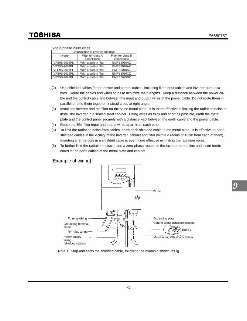
E6580757
I-3
9
Single-phase 200V classCombination of inverter and filter
Inverter Filter for class Acompliance
Filter for class Bcompliance
VFS9S-2002PL With a built-in filter EMFS2010AZVFS9S-2004PL With a built-in filter EMFS2010AZVFS9S-2007PL With a built-in filter EMFS2010AZVFS9S-2015PL With a built-in filter EMFS2016CZVFS9S-2022PL With a built-in filter EMFS2025DZ
(2) Use shielded cables for the power and control cables, including filter input cables and inverter output ca-bles. Route the cables and wires so as to minimize their lengths. Keep a distance between the power ca-ble and the control cable and between the input and output wires of the power cable. Do not route them inparallel or bind them together, instead cross at right angle.
(3) Install the inverter and the filter on the same metal plate. It is more effective in limiting the radiation noise toinstall the inverter in a sealed steel cabinet. Using wires as thick and short as possible, earth the metalplate and the control panel securely with a distance kept between the earth cable and the power cable.
(4) Route the EMI filter input and output wires apart from each other.(5) To limit the radiation noise from cables, earth each shielded cable to the metal plate. It is effective to earth
shielded cables in the vicinity of the inverter, cabinet and filter (within a radius of 10cm from each of them).Inserting a ferrite core in a shielded cable is even more effective in limiting the radiation noise.
(6) To further limit the radiation noise, insert a zero-phase reactor in the inverter output line and insert ferritecores in the earth cables of the metal plate and cabinet.
[Example of wiring]
VF-S9
Grounding plateControl wiring (Shielded cables)
(Note 1)
FL relay wiring
Grounding terminalscrew
RY relay wiringPower supplywiring(shielded cables)
Motor wiring (Shielded cables)
Note 1: Strip and earth the shielded cable, following the example shown in Fig.

E6580757
I-4
9
Shielded cableStrip the cable and fix it to the metalplate by means of a metal saddle forelectrical work or equivalent.
9.1.3 About the low-voltage directive
The low-voltage directive provides for the safety of machines and systems. All Toshiba inverters are CE-markedin accordance with the standard EN 50178 specified by the low-voltage directive, and can therefore be installed inmachines or systems and imported without problem to European countries.
Applicable standard: EN 50178Electronic equipment for use in power installations
Pollution level: 2 (5.2.15.2)Overvoltage category: 3
200V class - 3.0mm (5.2.16.1)400V class - 5.5mm (5.2.16.1)
EN 50178 applies to electrical equipment intended specially for use in power installations, and sets out the condi-tions to be observed for electric shock prevention when designing, testing, manufacturing and installing electronicequipment for use in power installations.
9.1.4 Measures to satisfy the low-voltage directive
When incorporating the inverter into a machine or system, it is necessary to take the following measures so thatthe inverter satisfies the low-voltage directive.(1) When installing the inverter outside the cabinet, provide a protective means for the inverter's wiring hole to
prevent workers from putting their fingers through the hole and touching an electrically-charged part in theinverter.
(2) Do not connect two or more wires to the main circuit earth terminal of the inverter. If necessary, install anadditional earth terminal on the metal plate on which the inverter is installed and connect another cable to it.Or install the EMC plate (attached as standard) and another cable connect to earth terminal on the EMCplate. Refer to the table 10.1 for earth cable sizes.
(3) Install a non-fuse circuit breaker on the input side of the inverter.

E6580757
J-1
10
10. Peripheral devices Danger
DangerMandatory
• When using switchgear for the inverter, it must be installed in a cabinet.Failure to do so can lead to risk of electric shock and can result in death or serious injury.
Be Grounded
• Connect earth cables securely. Failure to do so can lead to risk of electric shock or fire in case of afailure, short-circuit or leak current.
10.1 Selection of wiring materials and devicesWire size
Voltage classCapacity ofapplicablemotor (kW)
Inverter model Main circuit(mm2) (See Note 1.)
DC reactor(optional) (mm2)
Braking resistor/Braking unit
(optional) (mm2)
Groundingcable(mm2)
0.2 VFS9S-2002PL 2.0 1.25 1.25 3.50.4 VFS9S-2004PL 2.0 1.25 1.25 3.5
0.75 VFS9S-2007PL 2.0 2.0 1.25 3.51.5 VFS9S-2015PL 3.5 2.0 1.25 3.5
Single-phase200V class
2.2 VFS9S-2022PL 5.5 2.0 2.0 5.50.2 VFS9-2002PM 2.0 1.25 1.25 3.50.4 VFS9-2004PM 2.0 1.25 1.25 3.5
0.75 VFS9-2007PM 2.0 2.0 1.25 3.51.5 VFS9-2015PM 2.0 2.0 1.25 3.52.2 VFS9-2022PM 2.0 2.0 2.0 3.53.7 VFS9-2037PM 3.5 5.5 5.5 3.55.5 VFS9-2055PL 8.0 5.5 5.5 8.07.5 VFS9-2075PL 14 14 5.5 1411 VFS9-2110PM 14 14 5.5 14
Three-phase200V class
15 VFS9-2150PM 22 22 5.5 220.75 VFS9-4007PL 2.0 1.25 1.25 3.51.5 VFS9-4015PL 2.0 1.25 1.25 3.52.2 VFS9-4022PL 2.0 2.0 1.25 3.53.7 VFS9-4037PL 2.0 2.0 1.25 3.55.5 VFS9-4055PL 3.5 2.0 2.0 3.57.5 VFS9-4075PL 3.5 3.5 2.0 5.511 VFS9-4110PL 5.5 5.5 3.5 8.0
Three-phase400V class
15 VFS9-4150PL 8.0 8.0 3.5 8.0
Note 1: Sizes of the wires connected to the input terminals R, S and T and the output terminals U, V and W whenthe length of each wire does not exceed 30m.
Note 2: For the control circuit, use shielded wires 0.75 mm2 or more in diameter.Note 3: For grounding, use a cable with a size equal to or larger than the above.

E6580757
J-2
10
Selection of wiring devicesNon-fuse circuit
breaker(MCCB)
Magnetic contactor(MC)
Overload relay(THR)
Earth leakagebreaker(ELCB)Voltage class
Capacity ofapplicable
motor(kW)
Inverter model Ratedcurrent
(A)
TypeNote1)
Ratedcurrent
(A)
TypeNote1)
Adjusted current(A)
(For reference)
TypeNote1)
Ratedcurrent
(A)
TypeNote1)
0.2 VFS9S-2002PL 10 NJ30N 11 C11J 1.3 T13J 10 NJV50E0.4 VFS9S-2004PL 15 NJ30N 11 C11J 2.3 T13J 15 NJV50E0.75 VFS9S-2007PL 20 NJ30N 11 C11J 3.6 T13J 20 NJV50E1.5 VFS9S-2015PL 30 NJ30N 18 C20J 6.8 T13J 30 NJV50E
Single-phase200V class
2.2 VFS9S-2022PL 40 NJ50E 35 C35J 9.3 T13J 40 NJV50E0.2 VFS9-2002PM 5 NJ30N 11 C11J 1.3 T13J 5 NJV50E0.4 VFS9-2004PM 5 NJ30N 11 C11J 2.3 T13J 5 NJV50E0.75 VFS9-2007PM 10 NJ30N 11 C11J 3.6 T13J 10 NJV50E1.5 VFS9-2015PM 15 NJ30N 11 C11J 6.8 T13J 15 NJV50E2.2 VFS9-2022PM 20 NJ30N 13 C13J 9.3 T13J 20 NJV50E3.7 VFS9-2037PM 30 NJ30N 26 C25J 15 T20J 30 NJV50E5.5 VFS9-2055PL 50 NJ50E 35 C35J 22 T35J 50 NJV50E7.5 VFS9-2075PL 60 EJ100F 50 C50J 28 T35J 60 NJV60F11 VFS9-2110PM 100 EJ100F 65 C65J 44 T65J 100 NJV100F
Three-phase200V class
15 VFS9-2150PM 125 EJ225F 80 C80A 57 T65J 125 NJV225F0.75 VFS9-4007PL 5 NJ30N 9 C11J 1.6 T13J 5 NJV50E1.5 VFS9-4015PL 10 NJ30N 9 C11J 3.6 T13J 10 NJV50E2.2 VFS9-4022PL 15 NJ30N 9 C11J 5.0 T13J 15 NJV50E3.7 VFS9-4037PL 20 NJ30N 13 C13J 6.8 T13J 20 NJV50E5.5 VFS9-4055PL 30 NJ30N 17 C20J 11 T13J 30 NJV50E7.5 VFS9-4075PL 30 NJ30N 25 C25J 15 T20J 30 NJV50E11 VFS9-4110PL 50 EJ50E 33 C35J 22 T35J 50 NJV50E
Three-phase400V class
15 VFS9-4150PL 60 EJ100F 48 C50J 28 T35J 60 NJV100F
Note 1: Produced by Schneider Toshiba electric corporation.Note 2: Be sure to attach a surge killer to the exciting coil of the relay and the magnetic contactor.
Selection of surge killers for Toshiba magnetic contactors200V class: Surge absorbing units are optionally available for Toshiba C11J to C65J, or
Model SS-2 for C50J and C65J400V class: For the operation and control circuits, regulate the voltage at 200V or less with a step-down
transformer.Note 3: When using the auxiliary contacts 2a of the magnetic contactor MC for the control circuit, connect the
contacts 2a in parallel to increase reliability.
Of the wiring devices listed in the above table, the magnetic contactors (MC) and the overload relays (Th-Ry) areintended for use with the Mighty J series. When using the old series (ESPER Mighty series), refer to the tablebelow showing the correspondence between the two series.
Magnetic contactor (MC) Overload relayESPER Mighty series Mighty J series ESPER Mighty series Mighty J series
C12A C13J T11A T13JC20A C20J T20A T20JC35A C35J T35A T35JC50A C50J T65A T65JC65A C65J

E6580757
J-3
10
10.2 Installation of a magnetic contactor
If using the inverter without installing a magnetic contactor (MC) in the primary circuit, use an MCCB (with apower cutoff device) to open the primary circuit when the inverter protective circuit is activated.If using a braking resistor or braking resistor unit, install a magnetic contactor (MC) or non-fuse circuit breakerwith a power cutoff device to the power supply of the inverter, so that the power circuit opens when the failuredetection relay (FL) in the inverter or the external overload relay is activated.
Magnetic contactor in the primary circuitA magnetic contactor installed in the power supply circuit of the inverter cuts off the power supply to the cir-cuit and prevents the inverter from restarting in case of a power failure, a trip of the overload relay (Th-Ry)or the activation of the inverter protective circuit.In addition, if the FL contact of the failure detection relay in the VF-S9 is connected to the operation circuitof the magnetic contactor on the primary side, the magnetic contactor (MC) will be tripped when the inverterprotective circuit is activated.
MC
MC
IM
VF-S9
R/L1 U/T1
W/T2
W/T3
F
R
CC
S/L2
T/L3
FLC
FLB
FLA
MCCB
Power supply
Motor
Thermal relay
Forward run
Reverse runSurge killer
Example of connection of a magnetic contactor in the primary circuit
Notes on wiring• When frequently switching between start and stop, do not use the magnetic contactor on the primary side as
an on-off switch for the inverter. Instead, stop and start the inverter by using terminals F and CC (forward run)or R and CC (reverse run).
• Be sure to attach a surge killer to the exciting coil of the magnetic contactor (MC).
Magnetic contactor in the secondary circuitA magnetic contactor may be installed on the secondary side to switch controlled motors or supply com-mercial power to the load when the inverter is out of operation.
Notes on wiring• Be sure to interlock the magnetic contactor on the secondary side with the power supply to prevent commercial
power from being applied to the inverter output terminals.• When installing a magnetic contactor (MC) between the inverter and the motor, avoid turning the magnetic
contactor on or off during operation. Turning the magnetic contactor on or off during operation causes a cur-rent to rush into the inverter which could lead to malfunction.

E6580757
J-4
10
10.3 Installation of an overload relay
1) The VF-S9 inverter has an electronic-thermal overload protective function. In the following cases, however,the activation level of the electronic thermal protection unit must be adjusted and an overload relay suitablefor the motor installed between the inverter and the motor.• When using a motor with a current rating different to that of the corresponding Toshiba general-purpose
motor• When operating a single motor with an output smaller than that of the applicable standard motor or more
than one motor simultaneously2) When using the VF-S9 inverter to operate a constant-torque motor, such as the Toshiba VF motor, adjust
the protection characteristic of the electronic thermal protection unit to the VF motor use.3) It is recommended to use a motor with a thermal relay embedded in the motor coil to give sufficient protec-
tion to the motor, especially when it runs in a low-speed range.
10.4 Optional external devices
The following external devices are optionally available for the VF-S9 series of inverters.
Non-fuse circuitbreaker MCCB
Power supply
Magneticcontactor MC
Input ACreactor (ACL)
High-attenuationradio noise filterZero-phase reactorferrite core-type radionoise filter
Foot-mountednoise filter N.F
VF-S9
DC reactor
Brakingresistor
N.F
IM
Zero-phase reactorferrite core-type radionoise filter
Motor -end surgevoltage suppressionfilter (for 400Vmodels only)
Motor
(4)
(7)
(3)
(4)(5)
(2)
(6)
(1)

E6580757
J-5
10
Optional external devicesNo. Device Function and purpose
(1)
Input AC reactor Used to improve the input power factor, reduce the harmonics, and suppress externalsurge on the inverter power source side. Install when the power capacity is 500 kVA ormore and 10 times or more than the inverter capacity or when a distorted wave genera-tion source such as a thyristor unit or a large-capacity inverter is connected in the samedistribution system.
¹ Large : Large effective. ¹ : effective. × : ineffective
(2)
DC reactor Improves the power factor more than the input reactor. When the facility applying theinverter requires high reliability, it is recommended to use the DC reactor with an input re-actor effective for external surge suppression.* An inverter unit of 200V-3.7kW or less is connected to a reactor selected on page J-8, 9
to conform “Guides of limits for harmonics current emissions on general purposeinverter having an input current up to and including 20A per phase” by the Japan Elec-trical Manufacturers’ Association.
(3)
High-attenuation filter(LC filter)NF typemanufactured bySoshin Electric Co.
These types of filters are not necessary because all single-phase 200V or 3-phase 400Vmodels and 3-phase 200V, 5.5kW or 7.5kW models have a built-in EMI noise filter, con-forming to Class A, as standard. But install these filters if necessarily of noise reductionmove and more.• Effective to prevent interference in audio equipment used near the inverter.• Install on the input side of the inverter.• Provided with wide-range attenuation characteristics from AM radio bands to near
10MHz.• Use when equipment readily affected by noise is installed in the peripheral area.
(4)
Zero-phase reactor(Inductive filter)Ferrite core typemanufactured bySoshin Electric Co.
• Effective to prevent interference in audio equipment used near the inverter.• Effective in noise reduction on both input and output sides of the inverter.• Provided with attenuation characteristics of several dB in frequencies from AM radio
bands to 10MHz.• For noise countermeasures, insert on the secondary side of the inverter.
(5)
Rad
io n
oise
redu
ctio
n fil
ter
Foot-mounted typenoise reduction filter(Soon to bereleased)
High-attenuation EMI noise filter requiring only small space; mounted on the rear side ofthe inverter. This filter can be installed to conform to the following classes of EMC stan-dard EN5501 Group 1.3-phase 200V models excluding those of 5.5/7.5kW : Conform to Class A.All models other than above : Conform to Class B.
(6)
Braking resistor Use when rapid deceleration or stop is frequently required or when it is desired to reducethe deceleration time with large load. This resistor consumes regenerative energy duringpower generation braking.• Braking resistor – With (resistor + protective thermal relay) built in.
(7)Motor-end surge voltagesuppression filter (400Vclass only)
Use an insulation-reinforced motor or install the surge voltage restraint filter to preventdegrading motor insulation caused by surge voltage generation depending on cablelength and wiring method, or use of a 400V class motor driven with an inverter.
(8) Conduit pipe kit(Soon to be released)
Attachment kit used for conformance to NEMA TYPE1.
(9) IP43 enclosure kit(Soon to be released)
Attachment kit for making a panel conform to the IP43 structure.
(10) DIN rail kit(Soon to be released)
Available for the 200V class models of 0.75kW or less. (Model: DIN001Z)
EffectHarmonics SuppressionReactor type Power factor
improvement 200V-3.7kWor less Other model
External surgesuppression
Input AC reactor ¹ ¹ ¹ ¹DC reactor ¹ Large ¹ ¹ Large ×

E6580757
J-6
10
No. Device Function and purpose
(11) Parameter writer Use this unit for batch read, batch copy, and batch writing of setting parameters.(Model: PWU001Z)
(12)Extension panel Extended operation panel kit provided with LED indication section, RUN/STOP key,
UP/DOWN key, Monitor key, and Enter key.(Model: RKP001Z)
(13) RS485 communicationconverter unit
Use to connect a personal computer for data communication with up to 64 units.(Model: RS4001Z)
(14) RS232C communicationconverter unit
Use to connect a personal computer for data communication. (Model: RS2001Z)
(10)Remote panel Provided with built-in frequency indicator, frequency setting device, and RUN-STOP (for-
ward/reverse) switch.(Model: CBVR-7B1)
(15) Application control unit AP Series is available to enable various types of application control functions when com-bined with an inverter. Contact your Toshiba representative for further information.
Table for selection of optional external devicesRadio noise
reduction filterVoltageclass
Capacity ofapplicable
motorInverter model
Input ACreactor(Note 2)
DCreactor(Note 2)
High-attenuation
type
Core type(See Note 1.)
Brakingresistor
Motor-endsurge voltagesuppression
filter
Conduitpipe kit
Foot-mounted typenoise reduction filter
DINadapter
0.2 VFS9S-2002PL PFL-2002S DCLS-2002 - RC5078 PBR-2007 - NEM010Z EMFS2010AZ DIN001Z0.4 VFS9S-2004PL PFL-2005S DCL-2007 - RC5078 PBR-2007 - NEM010Z EMFS2010AZ DIN001Z
0.75 VFS9S-2007PL PFL-2011S DCL-2022 - RC5078 PBR-2007 - NEM010Z EMFS2010AZ DIN001Z1.5 VFS9S-2015PL PFL-2018S DCL-2037 - RC5078 PBR-2022 - NEM020Z EMFS2016CZ -
Single-phase200Vclass
2.2 VFS9S-2022PL PFL-2018S DCL-2037 - RC5078 PBR-2022 - NEM030Z EMFS2025DZ -0.2 VFS9-2002PM PFL-2001S DCL-2002 NF3005A-MJ RC5078 PBR-2007 NEM011Z EMF2011BZ DIN001Z0.4 VFS9-2004PM PFL-2005S DCL-2007 NF3005A-MJ RC5078 PBR-2007 - NEM011Z EMF2011BZ DIN001Z
0.75 VFS9-2007PM PFL-2005S DCL-2007 NF3005A-MJ RC5078 PBR-2007 - NEM011Z EMF2011BZ DIN001Z1.5 VFS9-2015PM PFL-2011S DCL-2022 NF3015A-MJ RC5078 PBR-2022 - NEM011Z EMF2011BZ -2.2 VFS9-2022PM PFL-2011S DCL-2022 NF3015A-MJ RC5078 PBR-2022 - NEM031Z EMF4022DZ -3.7 VFS9-2037PM PFL-2018S DCL-2037 NF3020A-MJ RC5078 PBR-2037 - NEM031Z EMF4022DZ -5.5 VFS9-2055PL PFL-2025S DCL-2055 - RC9129 PB3-2055 - NEM040Z EMF4045EZ -7.5 VFS9-2075PL PFL-2050S DCL-2110 - RC9129 PBR-2075 - NEM040Z EMF4045EZ -11 VFS9-2110PM PFL-2050S DCL-2110 NF3050A-MJ RC9129 PBR-2110 - NEM050Z EMF2080GZ
Three-phase200Vclass
15 VFS9-2150PM PFL-2100S DCL-2220 NF3080A-MJ RC9129 PBR-2150 - NEM050Z EMF2080GZ -0.75 VFS9-4007PL PFL-4012S DCL-2007 - RC5078 PBR-2007 MSF-4015Z NEM020Z EMF4006CZ -1.5 VFS9-4015PL PFL-4012S DCL-2007 - RC5078 PBR-2007 MSF-4015Z NEM020Z EMF4006CZ -2.2 VFS9-4022PL PFL-4012S DCL-2022 - RC5078 PBR-2007 MSF-4037Z NEM030Z EMF4022DZ -3.7 VFS9-4037PL PFL-4012S DCL-2022 - RC5078 PBR-2007 MSF-4037Z NEM030Z EMF4022DZ -5.5 VFS9-4055PL PFL-4025S DCL-4110 - RC9129 PBR3-4055 MSF-4075Z NEM040Z EMF4045EZ -7.5 VFS9-4075PL PFL-4025S DCL-4110 - RC9129 PBR3-4075 MSF-4075Z NEM040Z EMF4045EZ -
Three-phase400Vclass
11 VFS9-4110PL PFL-4025S DCL-4110 - RC9129 PBR3-4110 MSF-4150Z NEM050Z EMF4045FZ -15 VFS9-4150PL PFL-4050S DCL-4220 - RC9129 PBR3-4150 MSF-4150Z NEM050Z EMF4045FZ -
Note 1: This filter is used wound around the input-side power line. (Number of turns: 4 or more) This filter canbe installed on the output side, as well.
Note 2: Connecting this reactor to the inverter makes it compliant with the standard "General Inverter (inputcurrent of 20A or less) Harmonic Suppression Measures Execution Guidelines" set by the Japan Elec-tric Industry Association.

E6580757
J-7
10
Devices External dimensions and connectionsInput AC re-actor(ACL)
Dimensions (mm)Type Rating Inverter type
A B C D E F G Dra
win
g
TerminalsApprox.weight
(kg)PFLS2002S 1φ-230V-2.0A-50/60Hz VFS9S-2002PL 80 55 115 63 45 5 45 M3.5 0.85PFL2001S 3φ-230V-1.7A-50/60Hz VFS9-2002PM 105 65 115 90 55 5 40 M3.5 1.0
PFL2005S 3φ-230V-5.5A-50/60Hz VFS9-2004PM, 2007PMVFS9S-2004PL 105 65 115 90 55 5 40 M3.5 1.2
PFL2011S 3φ-230V-11A-50/60Hz VFS9S-2007PLVFS9-2015PM, 2022PM 130 70 140 115 60 5 50 M4 2.3
PFL2018S 3φ-230V-18A-50/60Hz VFS9-2037PM,VFS9S-2015PL, VFS9S-2022PL 130 70 140 115 60 5 50 M4 2.5
PFL2025S 3φ-230V-25A-50/60Hz VFS9-2055PL 125 100 130 50 83 7 -
A
M4 2.6PFL2050S 3φ-230V-50A-50/60Hz VFS9-2075PL, VFS9-2110PM 155 115 140 50 95 7 - M6 3.4PFL2100S 3φ-230V-100A-50/60Hz VFS9-2150PM 230 150 210 60 90 8 - M8 8.2PFL4012S 3φ-460V-12.5A-50/60Hz VFS9-4007PL ∼ VFS9-4037PL 125 95 130 50 79 7 - 2.3PFL4025S 3φ-460V-25A-50/60Hz VFS9-4055PL ∼ VFS9-4110PL 155 110 155 50 94 7 - M4 4.9PFL4050S 3φ-460V-50A-50/60Hz VFS9-4150PL 155 140 165 50 112 7 -
B
M6 6.6
Note) PFL2002S has 4 terminals.
VF-S9S
VF-S9
R
G
X
Y
U
V
U
V IM
S W
Fig.A FIg.B
Terminal box with cover
4-φF holes
Input AC reactor
Powersupply
Powersupply
Input AC reactorVF-S9
VF-S9S

E6580757
J-8
10
Devices External dimensions and connectionsDC reactor(DCL)
Dimensions (mm)Type
Ratedcurrent
(A)Inverter type
W H D X Y d1 d2 Dra
win
g
TerminalsApprox.weight
(kg)DCLS-2002 2.5 VFS9S-2002PL, VFS9-2002PM 79 50 44 66 - - - V1.25-3.5 0.6
DCL-2007 7VFS9-2004PM, 2007PMVFS9S-2004PLVFS9-4007PL, 4015PL Note)
92 65 70 82 - - - A V2-3.5 1.2
DCL-2022 14VFS9-2015PM, 2022PMVFS9S-2007PLVFS9-4022PL, 4037PL Note)
86 110 80 71 64 - - M4 2.2
DCL-2037 22.5 VFS9-2037PMVFS9S-2015PL, 2022PL 86 110 85 71 70 - 55
B
M4 2.5
DCL-2055 38 VFS9-2055PL 75 130 140 50 85 85 55 M5 1.9DCL-2110 75 VFS9-2075PL ∼ VFS9-2110PM 100 150 150 65 85 95 60 M6 2.4DCL-2220 150 VFS9-2150PM 117 170 190 90 90 130 -
CM8 4.3
DCL-4110 38 VFS9-4055PL ∼ VFS9-4110PL 95 150 165 70 90 105 60 M5 3.0DCL-4220 75 VFS9-4150PL 105 160 185 80 100 130 65
CM8 3.7
Note) VFS9-4007PL are used DC reactor for 200V class.
Fig.A
Fig.B
Fig.C
Terminal box with cover
Nameplate
4-φ7
Powersupply
DC reactor
4.4 × 6 slotted hole(DCLS-2002)4.4 × 6 slotted hole(DCL-2007)
Name plateName plate
Terminal box with cover

E6580757
J-10
10
Devices External dimensions and connectionsFoot-mountednoise filter
Dimensions (mm)Type
Ratedcurrent
(A)Inverter type
W H D W1 H1 D2 E F G Approx. weight(kg)
Remarks
EMFS2010AZ 10 VFS9S-2002PL ∼ 2007PL 185 170 EMC : class B complianceEMF2011BZ 11 VFS9-2002PM ∼ 2015PM
105 50 85 0.9 EMC : class A complianceEMFS2016CZ 16 VFS9-2015PL 1.2EMF4006CZ 6 VFS9S-4007PL, 4015PL 130 205 110 190
1.25EMFS2025DZ 25 VFS9S-2022PL 1.4
EMC : class B compliance
VFS9-2022PM, 2037PM EMC : class A complianceEMF4022DZ 22 VFS9-4022PL, 4037PL140 250 120 230
10 8.5 8.5
1.25
EMF4045EZ 45 VFS9-2055PL, 2075PLVFS9-4055PL, 4075PL 200 351 160 330 3.6
EMF4045FZ 45 VFS9-4110PL, 4150PL
EMC : class B compliance
EFM2080GZ 80 VFS9-2110PM, 2150PM 245 372
60
205 360
2
11 9.5 5.55 EMC : class A compliance *
* Wire grounding wire between the EMI filter and EMC plate in order to conform to class A.Wire size : 6mm2 or more (AWG 9 or more)Wire length : 29cm or less
D
D2
W
W1(Mounting dimension)
H
F
H1(
Mou
ntin
g di
men
sion
)
VF-S9 VF-S9
φG
φE
Filter

E6580757
J-11
10
VF-S9
VF-S9
Fig.C
Fig.D
Fig.A
Fig.B
RS
UV
IMT
B
C
A
E4.2
D
500 PAPB
W
IMUVW
PA
PA
PB
PB
TH2TH1
RST
MC
MC
E
E
ON
OFF
FLBFLC
TH1TH2
Devices External dimensions and connectionsBrakingresistor
Dimensions (mm)Model Rating Inverter type A B C D E GDiagram/
ConnectionApprox.
weight(kg)
PBR-2007 120W-200Ω VFS9-2002PM ∼ VFS9-2007PMVFS9S-2002PL ∼ VFS9S-2007PL
PBR-2022 120W-75Ω VFS9-2015PM ∼ VFS9-2022PMVFS9S-2015PL, 2022PL
PBR-2037 120W-40Ω VFS9-2037PM
42 182 20 4.2 172 - A&C 0.28
PBR3-2055 120W-40Ω x 2P(240W-20Ω) VFS9-2055PL 320 115 50 4PBR3-2075 220W-30Ω x 2P(440W-15Ω) VFS9-2075PL 4.5PBR3-2110 220W-30Ω x 3P(660W-10Ω) VFS9-2110PM 5PBR3-2150 220W-30Ω x 4P(880W-7.5Ω) VFS9-2150PM
120 350 190 110 230 150 B&D
5.5PBR-2007 120W-200Ω VFS9-4007PL ∼ VFS9-4022PL Note)PBR-4037 120W-160Ω VFS9-4037PL 42 182 20 4.2 172 - A&C 0.28
PBR3-4055 120W-160Ω x 2P(240W-80Ω) VFS9-4055PL 320 115 50 4PBR3-4075 220W-120Ω x 2P(440W-60Ω) VFS9-4075PL 4.5PBR3-4110 220W-120Ω x 3P(660W-40Ω) VFS9-4110PL 5PBR3-4150 220W-120Ω x 4P(880W-30Ω) VFS9-4150PL
120 350 190 110 230 150 B&D
5.5
Note) VFS9-4007PL ∼ 4022PL are used breaking resister for 200V class.
Powersupply
Braking resister
Powersupply
Wire opening
E
D
φ4.2
500
4-φ5 holes
E
D
Earth terminal(M5)
Braking resister
Connect to operation circuit

E6580757
J-12
10
Devices External dimensions and connectionsParameterwriter Exten-sion panelCommunica-tion Con-verter unit(RS485/RS232C)
延長パネルパラメータライタ 通信変換ユニット RS485/RS232C
延長パネル形式:RKP001Z延長パネル用ケーブル形式: CAB0011(1m) CAB0013(3m) CAB0015(5m)
パラメータライタ形式:PWU001Zパラメータライタ用ケーブル形式: CAB0011(1m) CAB0013(3m) CAB0015(5m)
RS232C通信変換ユニット形式:RS2001Zコンピュータ側ケーブル形式:CAB0025RS232C用ケーブル形式: CAB0011(1m) CAB0013(3m) CAB0015(5m)
RS485通信変換ユニット形式:RS4001ZRS485用ケーブル形式: CAB0011(1m) CAB0013(3m) CAB0015(5m)
注)延長パネルの外形寸法は下図と同じですが 盤面は下図と異なります。
注)下図はRS485のユニットです。 RS232Cユニットは外形寸法は同じですがコネクタ部がありません。
コネクタ部
Parameter writer Extension panel Communication ConverterNote) Dimensions of extension panel are
same as following drawing, but thesurface of panel are different.
Note) Following is RS485 unit. Dimensions of RS232C unit are same asfollowing, but RS232C doesn’t have a connector.
connector
Parameter writer type:PWU001Z
Parameter writer cable type:CAB0011 (1m)CAB0013 (3m)CAB0015 (5m)
Extension paneltype: PKP001ZExtension panelcable type: CAB0011 (1m)
CAB0013 (3m)CAB0015 (5m)
RS485 communicationconverter type: RS4001ZRS485 cable type:
CAB0011 (1m)CAB0013 (3m)CAB0015 (5m)
RS232C communicationconverter type: RS2001ZRS232C cable type:
CAB0011 (1m)CAB0013 (3m)CAB0015 (5m)

E6580757
K-1
11
11. Table of parameters and data11.1 User parameters
Title Function Unit Minimumsetting unit
Adjustment range Defaultsetting
Usersetting
Reference
- Applicable motorbase frequency *3
Hz - 6050
*1 4.1
Operationfrequency ofoperation panel
Hz 0.1 - 0.0 3.2
*3 : When the standard setting ( : ) is entered, this parameter displayed.
11.2 Basic parameters• Four automatic functions
Title CommunicationNo.
Function Unit Minimumsetting unit
Adjustment range Defaultsetting
Usersetting
Reference
0000 Automaticacceleration/deceleration
- - 0: Disabled (manual)1: Optimum rate2: Minimum rate
0 5.1
0001 Automatic torqueboost
- - 0: Disabled1: Vector control + auto-tuning
0 5.2
0002 Automaticenvironmentsetting
- - 0: Disabled1: Automatic setting
0 5.3
0040 Automatic functionsetting
- - 0: Disabled1: Coast stop2: 3-wire operation3: External input UP/DOWN setting4: 4-20 ma current input operation
0 5.4
• Other basic parametersTitle Communication
No.Function Unit Minimum
setting unitAdjustment range Default
settingUser
settingReference
0003 Command modeselection
- - 0: Terminal board1: Operation panel
1 5.5
0004 Frequency settingmode selection
- - 0: Terminal board1: Operation panel2: Internal potentiometer
2 5.5
0005 Meter selection - - 0: Output frequency1: Output current2: Set frequency3: For adjustment (current fixed at100%)4: Inverter load factor5: Output power
0 5.6
0006 Meter adjustment - - - 5.60007 Standard setting
mode selection- - 0 ∼ 2: -(invalid)
3: Default setting4: Trip clear5: Cumulative operation time clear6: Initialization of type information
0 5.7
*1 : The end of type – form dependAN – WN : 60HzWP : 50Hz
*2 : Model depend (See section 11 page K-6)

E6580757
K-2
11
Title CommunicationNo.
Function Unit Minimumsetting unit
Adjustment range Defaultsetting
Usersetting
Reference
0008 Forward/reverserun selection(Operation panel)
- - 0: Forward run1: Reverse run
0 5.8
0009 Accelerationtime 1
s 0.1 0.1-3600 10.0 5.1
0010 Decelerationtime 1
s 0.1 0.1-3600 10.0 5.1
0011 Maximumfrequency
Hz 0.1 30.0-400 80.0 5.9
0012 Upper limitfrequency
Hz 0.1 0.5- *1 5.10
00013 lower limitfrequency
Hz 0.1 0.0- 0.0 5.10
0014 Base frequency 1 Hz 0.1 25-400 60.0 *1 5.110015 V/F control mode
selection- - 0: V/F constant
1: Variable torque2: Automatic torque boost3: Sensorless Vector control4: Automatic energy-saving
0 5.12
0016 Torque boost %/(V) 0.1 0.0-30.0 *2 5.130041 Motor
electronic-thermalprotection level 1
%/(A) 1 10-100 100 5.14
Setting type Overload protection OL stall0 ¹ ×1 ¹ ¹2 × ×3
Standardmotor
× ¹4 ¹ ×5 ¹ ¹6 × ×
0017 Electronic-thermalprotectioncharacteristicselection *4
- -
7
VF motor(specialmotor)
× ¹
0 5.14
to0018
to0024
Preset-speedoperationfrequencies 1 to 7
Hz 0.1 - 0.0 5.15
____ - Extendedparameter
- - - - - 4.1
- Automatic editfunction
- - - - - 4.1
*4 : ¹ : valid, × : invalid
11.3 Extended parameters
• Input/output parametersTitle Communication
No.Function Unit Minimum
setting unitAdjustment range Default
settingUser
settingReference
0100 Low-speed signaloutput frequency
Hz 0.1 0.0- 0.0 6.1.1
0101 Speed reachsetting frequency
Hz 0.1 0.0- 0.0 6.1.3
0102 Speed reachdetection band
Hz 0.1 0.0- 2.5 6.1.2
0103 ST signalselection
- - 0: Stand by on when ST is on1: Stand by always on2: Interlocked with F/R3: Stand by on when ST is off
1 6.2.1
0104 RST signalselection
- - 0: Default1: Activated by turning RST off
0 6.2.2

E6580757
K-3
11
Title CommunicationNo.
Function Unit Minimumsetting unit
Adjustment range Defaultsetting
Usersetting
Reference
0110 Always-activefunction selection
- - 0-51 0 6.3.1
0111 Input terminalselection 1 (F)
- - 0-51 (F) 2 6.3.2
0112 Input terminalselection 2 (R)
- - 0-51 (R) 3 6.3.2
0113 Input terminalselection 3 (RST)
- - 0-51 (RST) 10 6.3.2
0114 Input terminalselection 4 (S1)
- - 0-51 (SS1) 6 6.3.2
0115 Input terminalselection 5 (S2)
- - 0-51 (SS2) 7 6.3.2
0116 Input terminalselection 6 (S3)
- - 0-51 (SS3) 8 6.3.2
0130 Output terminalselection 1(RY-RC)
- - 0-29 (LOW) 4 6.3.3
0131 Output terminalselection 2 (OUT)
- - 0-29 (RCH) 6 6.3.3
0132 Output terminalselection 3 (FL)
- - 0-29 (FL) 10 6.3.3
0170 Base frequency 2 Hz 0.1 25-400 *1 6.4.1
0172 Torque boost 2 %/(V) 0.1 0.0-30.0 *2 6.4.10173 Motor
electronic-thermalprotection level 2
%/(A) 1 10-100 100 6.4.1
• Frequency parametersTitle Communication
No.Function Unit Minimum
setting unitAdjustment range Default
settingUser
settingReference
0200 Frequency priorityselection
- - 0: VIA/II, VIB1: VIB, VIA/II2: External switching
(FCHG enabled)3: External contact UP/DOWN *54: External contact UP/DOWN *5
(Setting retained even if the poweris turned off)
5: VIAI/II + VB
0 6.5.1
0201 VIA/II input point 1setting
% 1 0-100 0 6.5.2
0202 VIA/II input point 1frequency
Hz 0.1 0.0-400.0 0.0 6.5.2
0203 VIA/II input point2setting
% 1 0-100 100 6.5.2
0204 VIA/II input point2frequency
Hz 0.1 0.0-400.0 *1 6.5.2
0210 VIB input point 1setting
% 1 0-100 0 6.5.2
Frequency UPresponse time *5
(0.1s) 1 0-100 0
0211 VIB input point 1frequency
Hz 0.1 0.0-400.0 0.0 6.5.2
Frequency UPstep width *5
0.1 0.0-400.0 0.0
0212 VIB input point 2setting
% 1 0-100 100 6.5.2
Frequency DOWNresponse time *5
(0.1s) 1 0-100 100
*5 : Set the parameter to or ,function of ∼ is bottom of paragraph.

E6580757
K-4
11
Title CommunicationNo.
Function Unit Minimumsetting unit
Adjustment range Defaultsetting
Usersetting
Reference
0213 VIB input point 2frequency
Hz 0.1 0-400 *1 6.5.2
Frequency DOWNstep width *5
0.1 0.0-400.0 *1
0240 Starting frequencysetting
Hz 0.1 0.5-10.0 0.5 6.6.1
0241 Operation startingfrequency
Hz 0.1 0.0- 0.0 6.6.2
0242 Operation startingfrequency hysteri-sis
Hz 0.1 0.0- 0.0 6.6.2
0250 DC brakingstarting frequency
Hz 0.1 0.0- 0.0 6.7.1
0251 DC braking cur-rent
%/(A) 1 0-100 30 6.7.1
0252 DC braking time s 0.1 0.0-20.0 1.0 6.7.10260 Jog run stopping
patternHz 0.1 0.0-20.0 0.0 6.8
0261 Jog run stoppingpattern
- - 0: Slowdown stop1: Coast stop2: DC braking
0 6.8
0270 Jump frequency 1 Hz 0.1 - 0.0 6.9
0271 Jumping width 1 Hz 0.1 0.0-30.0 0.0 6.9
0272 Jump frequency 2 Hz 0.1 - 0.0 6.9
0273 Jumping width 2 Hz 0.1 0.0-30.0 0.0 6.9
0274 Jump frequency 3 Hz 0.1 - 0.0 6.9
0275 Jumping width 3 Hz 0.1 0.0-30.0 0.0 6.9
0280 Preset-speedoperation frequencies 1 Hz 0.1 - 0.0
0281 Preset-speedoperation frequencies 2 Hz 0.1 - 0.0
0282 Preset-speedoperation frequencies 3 Hz 0.1 - 0.0
0283 Preset-speedoperation frequencies 4 Hz 0.1 - 0.0
0284 Preset-speedoperation frequencies 5 Hz 0.1 - 0.0
0285 Preset-speedoperation frequencies 6 Hz 0.1 - 0.0
0286 Preset-speedoperation frequencies 7 Hz 0.1 - 0.0
0287 Preset-speedoperation frequencies 8 Hz 0.1 - 0.0
0288 Preset-speedoperation frequencies 9 Hz 0.1 - 0.0
0289 Preset-speedoperation frequencies 10 Hz 0.1 - 0.0
0290 Preset-speedoperation frequencies 11 Hz 0.1 - 0.0
0291 Preset-speedoperation frequencies 12 Hz 0.1 - 0.0
0292 Preset-speedoperation frequencies 13 Hz 0.1 - 0.0
0293 Preset-speedoperation frequencies 14 Hz 0.1 - 0.0
0294 Preset-speedoperation frequencies 15 Hz 0.1 - 0.0
5.15

E6580757
K-5
11
• Operation mode parametersTitle Communication
No.Function Unit Minimum
setting unitAdjustment range Default
settingUser
settingReference
0300 PWM carrierfrequency
kHz 0.1 2.0-16.5 12.0 6.11
0301 Auto-restartcontrol selection
- - 0: Disabled1: At auto-restart after momentary stop2: When turning ST-CC on or off3: At auto-restart or when turning
ST-CC on or off4: Motion of DC braking at start-up
(at auto-restart after momentarystop)
5: Motion of DC braking at start-up(when turning ST-CC on or off)
6: Motion of DC braking at start-up(at auto-restart or when turningST-CC on or off)
0 6.12.1
0302 Regenerativepower ride-through control
- - 0: Disabled1: Enabled
0 6.12.2
0303 Retry selection(number of times)
Times 1 0-10 0 6.12.3
0304 Dynamic brakingselection
- - 0: Dynamic braking disabled1: Dynamic braking enabled, over-
load protection disabled2: Dynamic braking enabled, over-
load protection enabled
0 6.12.4
0305 Overvoltage limitoperation
- - 0: Enabled1: Prohibited
0 6.12.5
0306 Output voltageadjustment (Basefrequency voltage)
V 1 0 to 250V, 0 to 500V 200V/400V 6.12.6
0307 Supply voltagecorrection
- - 0: Supply voltage uncorrected, outputvoltage limited
1: Supply voltage corrected, outputvoltage limited
2: Supply voltage corrected (off dur-ing deceleration), output voltagelimited
3: Supply voltage uncorrected, outputvoltage unlimited
4: Supply voltage corrected, outputvoltage unlimited
5: Supply voltage corrected (off dur-ing deceleration), output voltageunlimited
1 6.12.6
0308 Braking resistoroperation rate
%ED 1 1-100 3 6.12.4
0312 Random mode - - 0: Disabled1: Enabled
0 6.11
0360 PI control - - 0: Disabled1: Enabled
0 6.12.7
0362 Proportional gain - - 0-01-100.0 0.30 6.12.7
0363 Integral gain - - 0.01-100.0 0.20 6.12.7

E6580757
K-6
11
• Torque boost parametersTitle Communication
No.Function Unit Minimum
setting unitAdjustment range Default
settingUser
settingReference
0400 Auto-tuning - - 0: Auto-tuning disabled (use of inter-nal parameters)
1: Application of individual settings of to
2: Auto-tuning enabled (returns to 1after auto-tuning)
0 6.13
0401 Slip frequency Hz - 0.0-10.0 *2 6.130402 Motor primary
constant- - 0-255 *2 6.13
0403 Motor secondaryconstant
- - 0-255 *2 6.13
0404 Motor excitationconstant
- - 0-255 *2 6.13
0405 Magnification ofload inertial mo-ment
Times - 0-200 0 6.13
0408 Rated capacityratio of motor toinverter
- - 0: Same capacity as inverter1: One-size smaller than inverter
0 6.13
• Acceleration/deceleration time parametersTitle Communication
No.Function Unit Minimum
setting unitAdjustment range Default
settingUser
settingReference
0500 Accelerationtime 2
s 0.1 0.1-3600 10.0 6.14
0501 Decelerationtime 2
s 0.1 0.1-3600 10.0 6.14
0502 Acceleration/deceleration 1pattern
- - 0 6.14
0503 Accelerationdeceleration 2pattern
- -
0: Linear1: S-pattern 12: S-pattern 2
0 6.14
0504 Acceleration/deceleration pat-tern selection(1 or 2)
- - 0: Acceleration/deceleration 11: Acceleration/deceleration 2
0 6.14
0505 Acceleration/deceleration 1 and2 switchingfrequency
Hz 0.1 0- 0.0 6.14
• Protection parametersTitle Communication
No.Function Unit Minimum
setting unitAdjustment range Default
settingUser
settingReference
0600 Motor electronic-thermal protectionlevel 1
%/(A) 1 10-100 100 6.15.1
0601 Stall preventionlevel
%/(A) 1 10-199200 (disabled)
150 6.15.2
0602 Inverter trip reten-tion selection
- - 0: Not retained1: Retained
0 6.15.3
0603 External input tripstop mode selec-tion
- - 0: Coast stop1: Slowdown stop2: Emergency DC braking
0 6.15.4
0604 Emergency DCbraking time s 0.1 0.0-20.0 1.0 6.15.4
0605 Output phasefailure detectionmode selection
- - 0: Disabled1: Enabled (during operation)2: Enabled (disabled during auto-restart)
0 6.15.5

E6580757
K-7
11
Title CommunicationNo.
Function Unit Minimumsetting unit
Adjustment range Defaultsetting
Usersetting
Reference
0608 Input phase failuredetection modeselection
- - 0: Disabled1: Enabled
1 6.15.6
0610 Small current tripselection
- - 0: Disabled1: Enabled
0 6.15.7
0611 Small current(trip/alarm)detection current
% 1 0-100 0 6.15.7
0612 Small current(trip/alarm) detec-tion time
s 1 0-255 0 6.15.7
0615 Over-torque tripselection
- 0: Disabled1: Enabled
0 6.15.8
0616 Over-torque(trip/alarm) level
% 1 0-200 150 6.15.8
0618 Over-torquedetection time
s 0.1 0-10 0.5 6.15.8
0619 Over-torque (tripalarm) levelhysterisis
% 1 0-100 10 6.15.8
0627 Undervoltage tripselection
- - 0: Disabled1: Enabled (Trip at 70% or less)2: Disabled (Stop (not trip) at 50% or
less)
0 6.15.9
0692 Meter bias % 1 0-50 0 6.15.10
• Operation panel parametersTitle Communication
No.Function Unit Minimum
setting unitAdjustment range Default
settingUser
settingReference
0700 Prohibition ofchange ofparameter settings
- - 0: Permitted ( and cannot be changed duringoperation.)
1: Prohibited2: Permitted ( and
also can be changed duringoperation.)
0 6.16.1
0701 Unit selection - - 0: No change1: % Ą A (ampere)/V (volt)2: Free unit selection enabled
( )3: % Ą A (ampere)/V (volt)
Free unit selection enabled( )
0 6.16.2
0702 Free unit selection - 0.01 0.01-200.0 1.00 6.16.20710 Standard monitor
display selection- - 0: Operation frequency (Hz/free unit)
1: Output current (%/A)2. Frequency command (Hz/free unit)3: Inverter rated current (A)4: Inverter over load factor (%)5: Output power (%)
0 6.16.3
• Communication parametersTitle Communication
No.Function Unit Minimum
setting unitAdjustment range Default
settingUser
settingRefer-ence
0800 Communicationband speed
- - 0:1200bps , 1:2400bps , 2:4800bps3:9600bps , 4:19200bps
3 6.17
0801 Parity - - 0:NON, 1:EVEN, 2:ODD 1 6.170802 Inverter number - 1 0-63 0 6.170803 Communication
error trip times 1 0 (Disabled) , 1-100 0 6.17

E6580757
K-8
11
Default settings by inverter ratingInverter model Torque boost Slip frequency Motor primary
constantMotor secon-dary constant
Motor excitationconstant
/VFS9S-2002PL 6.0% 3.0Hz 33 35 35VFS9S-2004PL 6.0% 3.0Hz 36 39 39VFS9S-2007PL 6.0% 3.0Hz 36 28 44VFS9S-2015PL 6.0% 2.7Hz 26 16 42VFS9S-2022PL 5.0% 2.7Hz 28 17 44VFS9-2002PM 6.0% 3.0Hz 33 35 35VFS9-2004PM 6.0% 3.0Hz 36 39 39VFS9-2007PM 6.0% 3.0Hz 36 28 44VFS9-2015PM 6.0% 2.7Hz 26 16 42VFS9-2022PM 5.0% 2.7Hz 28 17 44VFS9-2037PM 5.0% 2.7Hz 27 15 37VFS9-2055PL 4.0% 2.0Hz 17 11 37VFS9-2075PL 3.0% 2.0Hz 13 12 36VFS9-2110PM 2.0% 1.7Hz 13 11 42VFS9-2150PM 2.0% 1.7Hz 9 11 37VFS9-4007PL 6.0% 3.0Hz 27 15 38VFS9-4015PL 6.0% 2.7Hz 28 16 39VFS9-4022PL 5.0% 2.7Hz 28 39 39VFS9-4037PL 5.0% 2.7Hz 28 26 41VFS9-4055PL 4.0% 2.0Hz 17 11 43VFS9-4075PL 3.0% 2.0Hz 13 12 37VFS9-4110PL 2.0% 1.7Hz 13 11 42VFS9-4150PL 2.0% 1.7Hz 9 11 37
Table of input terminal functions (1/3)Function
No.Code Function Action
0 - No function is assigned Disabled1 ST Standby terminal When is set at - ON:
Gate on, OFF: Gate off (free-run)When is set at - OFF:
Gate on, ON: Gate off (free-run)2 F Forward-run command ON: Forward run
OFF: Slowdown stop3 R Reverse-run command ON: Reverse run
OFF: Slowdown stop (Reverse run has priority.)4 JOG Jog run command ON: Jog run, OFF: Jog run canceled5 AD2 Acceleration/deceleration 2 pattern selection ON: Acceleration/deceleration 2, OFF: Accelera-
tion/deceleration 16 SS1 Preset-speed command 17 SS2 Preset-speed command 28 SS3 Preset-speed command 39 SS4 Preset-speed command 4
Selection of 15-speed with SS1 to SS4 (4 bits)
10 RST Reset command ON → OFF: Trip reset11 EXT Trip stop command from external input device ON: trip stop12 PNL/TB Operation panel/terminal board switching ON: Forced switching from panel control (Internal
potentiometer)to terminal board control13 DB DC braking command ON: DC braking14 PI Prohibition of PI control ON: PI control prohibited
OFF: PI control permitted15 PWENE Permission of parameter editing ON: Parameter editing permitted, OFF: Parameter
editing prohibited

E6580757
K-9
11
Table of input terminal functions (2/3)Function
No.Code Function Action
16 ST+RST Combination of standby and reset commands ON: Simultaneous input from ST and RST17 ST+PNL/TB Combination of standby and operation
panel/terminal board switchingON: Simultaneous input from ST and PNL/TB
18 F+JOG Combination of forward run and jog run ON: Simultaneous input from F and JOG19 R+JOG Combination of reverse run and jog run ON: Simultaneous input from R and JOG20 F+AD2 Combination of forward run and acceleration/
deceleration 2ON: Simultaneous input from F and AD2
21 R+AD2 Combination of reverse run and acceleration/deceleration 2
ON: Simultaneous input from R and AD2
22 F+SS1 Combination of forward run and preset-speedcommand 1
ON: Simultaneous input from F and SS1
23 R+SS1 Combination of reverse run and preset-speedcommand 1
ON: Simultaneous input from R and SS1
24 F+SS2 Combination of forward run and preset-speedcommand 2
ON: Simultaneous input from F and SS2
25 R+SS2 Combination of reverse run and preset-speedcommand 2
ON: Simultaneous input from R and SS2
26 F+SS3 Combination of forward run and preset-speedcommand 3
ON: Simultaneous input from F and SS3
27 R+SS3 Combination of reverse run and preset-speedcommand 3
ON: Simultaneous input from R and SS3
28 F+SS4 Combination of forward run and preset-speedcommand 4
ON: Simultaneous input from F and SS4
29 R+SS4 Combination of reverse run and preset-speedcommand 4
ON: Simultaneous input from R and SS4
30 F+SS1+AD2 Combination of forward run, preset-speedcommand 1 and acceleration/deceleration 2
ON: Simultaneous input from F, SS1 and AD2
31 R+SS1+AD2 Combination of reverse run, preset-speedcommand 1 and acceleration/deceleration 2
ON: Simultaneous input from R, SS1 and AD2
32 F+SS2+AD2 Combination of forward run, preset-speedcommand 2 and acceleration/deceleration 2
ON: Simultaneous input from F, SS2 and AD2
33 R+SS2+AD2 Combination of reverse run, preset-speedcommand 2 and acceleration/deceleration 2
ON: Simultaneous input from R, SS2 and AD2
34 F+SS3+AD2 Combination of forward run, preset-speedcommand 3 and acceleration/deceleration 2
ON: Simultaneous input from F, SS3 and AD2
35 R+SS3+AD2 Combination of reverse run, preset-speedcommand 3 and acceleration/deceleration 2
ON: Simultaneous input from R, SS3 and AD2
36 F+SS4+AD2 Combination of forward run, preset-speedcommand 4 and acceleration/deceleration 2
ON: Simultaneous input from F, SS4 and AD2
37 R+SS4+AD2 Combination of reverse run, preset-speedcommand 4 and acceleration/deceleration 2
ON: Simultaneous input from R, SS4 and AD2
38 FCHG Frequency command forced switching Enabled if : 2ON: VIBOFF: VIA/II
39 THR2 No. 2 thermal switching ON: No. 2 thermal(.... : 0, , , )
OFF: No. 1 thermal( setting: , , )
40 MCHG No. 2 motor switching ON: No. 2 motor(.... : 0, , , , , , )
OFF: No. 1 motor( setting: , , , , , )
41 UP Frequency UP signal input from external contacts Enabled if ON: Increase in frequency
42 DOWN Frequency DOWN signal input from externalcontacts
Enabled if ON: Decrease in frequency
43 CLR Frequency UP/DOWN clear signal input fromexternal contacts
Off→ON: Resetting of UP/DOWN frequency bymeans of external contacts
44 CLR+RST Combination of frequency UP/DOWN clear andreset by means of external contacts
ON: Simultaneous input from CLR and RST

E6580757
K-10
11
Table of input terminal functions (3/3)Function
No.Code Function Action
45 EXTN Inversion of trip stop command from external de-vice
OFF: -trip stop
46 OH Thermal trip stop signal input from external device ON: trip stop47 OHN Inversion of thermal trip stop command from ex-
ternal deviceOFF: trip stop
48 SC/LC Remote/local control forced switching Enabled when remote control is exercisedON: Local control
(setting of and )OFF: Remote control
49 HD Operation holding (stop of 3-wire operation) ON: F (forward run)/R: (reverse run) held, 3-wireoperation
OFF: Slowdown stop50 SDBF Forward run after DC braking ON: Forward run after DC braking
OFF: Slowdown stop51 SDBR Reverse run after DC braking ON: Reverse run after DC braking
OFF: Slowdown stop
Table of output terminal functions (1/2)Function
No.Code Function Action
0 LL Frequency lower limit ON: Output frequency is equal to or higher than value.
OFF: Output frequency is lower than value.
1 LLN Inversion of frequency lower limit Inversion of LL setting2 UL Frequency upper limit ON: Output frequency is equal to or higher than
value.OFF: Output frequency is lower than
value.3 ULN Inversion of frequency upper limit Inversion of UL setting4 LOW Low-speed detection signal ON: Output frequency is equal to or higher than
set value.OFF: Output frequency is lower than
set value.5 LOWN Inversion of low-speed detection signal Inversion of LOW setting6 RCH Designated frequency reach signal (completion of
acceleration/deceleration)ON: Output frequency is within (input frequency
± set frequency).OFF: Output frequency exceeds (input frequency
± set frequency).
7 RCHN Inversion of designated frequency reach signal(inversion of completion of acceleration/deceleration)
Inversion of RCH setting
8 RCHF Set frequency reach signal ON: Output frequency is within( set frequency ± setfrequency).
OFF: Output frequency exceeds( set frequency ± setfrequency).
9 RCHFN Inversion of set frequency reach signal Inversion of RCHF setting10 FL Failure FL (trip output) ON: When inverter is tripped
OFF: When inverter is not tripped11 FLN Inversion of failure FL (inversion of trip output) Inversion of FL setting12 OT Over-torque detection ON: Torque current is equal to or larger than
set value and longer than set time.OFF: Torque current is lower than set
value.13 OTN Inversion of over-torque detection Inversion of OT setting14 RUN RUN/STOP ON: When operation frequency is output or during
DC braking ( )OFF: Operation stopped

E6580757
K-11
11
Table of output terminal functions (2/2)Function
No.Code Function Action
15 RUNN Inversion of RUN/STOP Inversion of RUN setting16 POL OL pre-alarm ON: 50% or more of calculated value of overload
protection levelOFF: Less than 50% of calculated value of over-
load protection level17 POLN Inversion of OL pre-alarm Inversion of POL setting18 POHR Braking resistor overload pre-alarm ON: 50% or more of calculated value of set
overload protection levelOFF: Less than 50% of calculated value of
set overload protection level19 POHRN Inversion of braking resistor overload pre-alarm Inversion of POHR setting20 POT Over-torque detection pre-alarm ON: Torque current is equal to or larger than 70%
of set value.OFF: Torque current is smaller than 70% of
set value.21 POTN Inversion of over-torque detection pre-alarm Inversion of POT setting22 PAL Pre-alarm ON: When POL, POHR or POT is on, or , or
issues an alarmOFF: When POL, POHR and POT are off, and ,
and issue no alarm23 PALN Inversion of pre-alarm Inversion of PAL setting24 UC Low-current detection ON: Output current is equal to or larger than
set value and longer than set time.OFF: Output current is smaller than set
value.25 UCN Inversion of low-current detection Inversion of UC setting26 HFL Hard fault ON: Tripping ( , , , , ,
, , , , , , )
OFF: Failure other than the above27 HFLN Inversion of hard fault Inversion of HFL setting28 LFL Soft fault ON: Tripping ( , , , ,
, )OFF: Failure other than the above
29 LFLN Inversion of soft fault Inversion of LFL setting
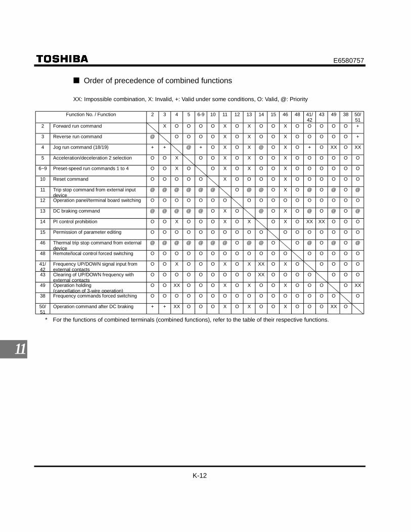
E6580757
K-12
11
Order of precedence of combined functions
XX: Impossible combination, X: Invalid, +: Valid under some conditions, O: Valid, @: Priority
Function No. / Function 2 3 4 5 6-9 10 11 12 13 14 15 46 48 41/42
43 49 38 50/51
2 Forward run command X O O O O X O X O O X O O O O O +
3 Reverse run command @ O O O O X O X O O X O O O O O +
4 Jog run command (18/19) + + @ + O X O X @ O X O + O XX O XX
5 Acceleration/deceleration 2 selection O O X O O X O X O O X O O O O O O
6~9 Preset-speed run commands 1 to 4 O O X O O X O X O O X O O O O O O
10 Reset command O O O O O X O O O O X O O O O O O
11 Trip stop command from external inputdevice
@ @ @ @ @ @ O @ @ O X O @ O @ O @
12 Operation panel/terminal board switching O O O O O O O O O O O O O O O O O
13 DC braking command @ @ @ @ @ O X O @ O X O @ O @ O @
14 PI control prohibition O O X O O O X O X O X O XX XX O O O
15 Permission of parameter editing O O O O O O O O O O O O O O O O O
46 Thermal trip stop command from externaldevice
@ @ @ @ @ @ @ O @ @ O O @ O @ O @
48 Remote/local control forced switching O O O O O O O O O O O O O O O O O
41/42
Frequency UP/DOWN signal input fromexternal contacts
O O X O O O X O X XX O X O O O O O
43 Clearing of UP/DOWN frequency withexternal contacts
O O O O O O O O O XX O O O O O O O
49 Operation holding(cancellation of 3-wire operation)
O O XX O O O X O X O O X O O O O XX
38 Frequency commands forced switching O O O O O O O O O O O O O O O O O
50/51
Operation command after DC braking + + XX O O O X O X O O X O O O XX O
* For the functions of combined terminals (combined functions), refer to the table of their respective functions.

E6580757
L-1
12
12. Specifications12.1 Models and their standard specifications
Standard specificationsItem Specification
Input voltage 3-phase 200VApplicable motor (kW) 0.2 0.4 0.75 1.5 2.2 3.7 5.5 7.5 11 15
Type VFS9-Form 2002PM 2004PM 2007PM 2015PM 2022PM 2037PM 2055PL 2075PL 2110PM 2150PM
Capacity (kVA) Note 1) 0.6 1.3 1.8 3.0 4.2 6.7 10 13 21 25Rated output current
(A) Note 2)1.5
(1.5)3.3
(3.3)4.8
(4.4)7.8
(7.5)11.0
(10.0)17.5
(16.5)27.525.0
33(33)
54(49)
66(60)
Rated output voltage Note 3) 3-phase 200V to 230V
Rat
ing
Overload current rating 60 seconds at 150%, 0.5 seconds at 200%Voltage-frequency 3-phase 200V to 230V – 50/60Hz
Pow
ersu
pply
Allowable fluctuation Voltage + 10%, -15% Note 4), frequency ±5%Protective method IP20 Enclosed type (JEM1030)
Cooling method Selfcooling Forced air-cooled
Color Munsel 5Y+8/0.5Built-in filter Standard EMI filter High-attenuation EMI filter Standard EMI filter
Item SpecificationInput voltage 1-phase 200V 3-phase 400VApplicable motor (kW) 0.2 0.4 0.75 1.5 2.2 0.75 1.5 2.2 3.7 5.5 7.5 11 15
Type VFS9S- VFS9-Form 2002PL 2004PL 2007PL 2015PL 2022PL 4007PL 4015PL 4022PL 4037PL 4055PL 4075PL 4110PL 4150PL
Capacity (kVA) Note 1) 0.6 1.3 1.8 3.0 4.2 1.8 3.1 4.2 7.2 11 13 21 25Rated output current
(A) Note 2)1.5
(1.5)3.3
(3.3)4.8
(4.4)7.8
(7.5)11.0
(10.0)2.3
(2.1)4.1
(3.7)5.5
(5.0)9.5
(8.6)14.3
(13.0)17.0
(17.0)27.7
(25.0)33
(30)Rated output voltage Note 3) 3-phase 200V to 240V 3-phase 380V to 500V
Rat
ing
Overload current rating 60 seconds at 150%, 0.5 seconds at 200% 60 seconds at 150%, 0.5 seconds at 200%Voltage-frequency 3-phase 200V to 240V – 50/60Hz 3-phase 380V to 500V – 50/60Hz
Pow
ersu
pply
Allowable fluctuation Voltage +10%, -15% Note 4), frequency ±5% Voltage +10%, -15% Note 4), frequency ±5%Protective method IP20 Enclosed type (JEM1030) IP20 Enclosed type (JEM1030)Cooling method Self
cooling Forced air-cooled Forced air-cooledColor Munsel 5Y+8/0.5 Munsel 5Y+8/0.5Built-in filter High-attenuation EMI filter High-attenuation EMI filter
Note) 1. Capacity is calculated at 220V for the 200V models and at 440V for the 400V models.Note) 2. Indicates rated output current setting when the PWM carrier frequency (parameter F300) is 4kHz or less.
When exceeding 4kHz, the rated output current setting is indicated in the parenthesis. When the input power voltage ofthe 400V class model exceeds 480V, it is necessary to further reduce the setting. The default setting of the PWM car-rier frequency is 12kHz.
Note) 3. Maximum output voltage is the same as the input voltage.Note) 4. ±10% when the inverter is used continuously (load of 100%).

E6580757
L-2
12
Item SpecificationControl system Sinusoidal PWM controlRated output voltage Adjustable within a range of 100 to 120% of the corrected supply voltage (200/400V) (Unadjustable to any voltage
higher than the input voltage).Output frequency range 0.5 to 400Hz, default setting: 0.5 to 80Hz, maximum frequency: 30 to 400Hz.Minimum setting steps offrequency
0.1Hz: operation panel setting, 0.2Hz: analog input (when the max. frequency is 100Hz).
Frequency accuracy Digital setting: within ±0.01% of the max. frequency (-10 to +50°C).Analog setting: within ±0.5% of the max. frequency (25°C ±10°C).
Voltage/frequencycharacteristics
V/f constant, variable torque, vector control, automatic torque boost, Base frequency and torque boost amount ad-justable.
Prin
cipa
l con
trol f
unct
ions
Frequency setting signal Front potentiometer and external potentiometer (rated impedance of connectable potentiometer: 1 to 10kΩ), 0 to10Vdc (input impedance: VIA=30.55kΩ, VB=30kΩ), 4 to 20mAdc (input impedance: 400Ω), The characteristic canbe set arbitrarily by two-point setting.
Start-up fre-quency/frequency jump
Adjustable within a range of 0 to 10Hz / Up to 3 frequencies can be adjusted together with their widths.
PWM carrier frequency(Note 1)
Adjustable within a range of 2.0 to 16.5Hz (default: 12kHz).
Acceleration/decelerationtime
0.1 to 3600 seconds, switchable between acceleration/deceleration time 1 and 2, selectable between S-pattern ac-celeration/deceleration 1 and 2.
Retry operation Restart after a check of the main circuit elements in case the protective function is activated: 10 times (Max.) (ad-justable with a parameter).
Dynamic braking With a built-in dynamic braking circuit, external braking resistor available (optional).DC braking Braking start-up frequency: 0 to maximum frequency, braking rate: 0 to 100%, braking time: 0 to 20 seconds.Input terminal functions(selectable)
Forward/reverse run input signal, jog run input signal, standby signal, preset-speed operation input signal, reset in-put signal, etc./Switching between sink/source.
Output terminal functions(selectable)
Frequency lower limit output signal, frequency upper limit output signal, low-speed detection output signal, specifiedspeed attainment output signal, etc. Open collector, RY output.
Failure detection signal 1c-contact output: 250Vac/2A, cosφ = 0.1, 250Vac/1A, cosφ = 0.4, 3Vdc/1A.
Ope
ratio
n sp
ecifi
catio
ns
Output for frequencymeter/output for ammeter
Analog output: (1mAdc full-scale DC ammeter or 7.5Vdc full-scale DC ammeter / Rectifier-type AC voltmeter, 225%current Max. 1mAdc, 7.5Vdc full-scale), 4 to 20mA/0 to 20mA output.
Protective function Stall prevention, current limitation, over-current, output short circuit, over-voltage, over-voltage limitation, undervolt-age, ground fault, power supply phase failure, output phase failure overload protection by electronic thermal func-tion, armature over-load at start-up (5.5kW or larger), load-side over—torque at start, pre-alarm, overheat.
Protection againstmomentary power failure
Auto-restart/non-stop control after momentary power failure.
Prot
ectiv
efu
nctio
n
Electronic thermalcharacteristic
Switching between standard motor/constant-torque VF motor, overload trip, overload stall selection.
4-digit 7-segments LED Frequency: inverter output frequency.Alarm: stall alarm “C”, overvoltage alarm “P”, overload alarm “L”, overheat alarm “H”.Status: inverter status (frequency, cause of activation of protective function, input/output voltage, output
current, etc.) and parameter settings.Free-unit display: arbitrary unit (e.g. rotating speed) corresponding to output frequency.
Dis
play
func
tion
Indicator Lamps indicating the inverter status by lighting, such as RUN lamp, MON lamp, PRG lamp, VEC lamp, ECN lamp,frequency setting potentiometer lamp, UP/DOWN key lamp and RUN key lamp. The charge lamp indicates that themain circuit capacitors are electrically charged.
Use environments Indoor, altitude: 1000m (Max.), not exposed to direct sunlight, corrosive gas, explosive gas or vibration (less than5.9m/s2) (10 to 55Hz).
Ambient temperature -10 to +60°C Note)1.2.3Storage temperature -20 to +65°C
Envi
ronm
ents
Relative humidity 20 to 93% (free from condensation and vapor).
Note) 1. Above 40°C : Remove the protective seal from the top of VF-S9.Note) 2. Above 50°C : Remove the protective seal from the top of VF-S9, and derate the rated output current by 3% for every
°C above 50°C.Note) 3. Side-by-side installation
• Model of 3.7kW or less : from - 10°C to 40°C (Remove the protective seal from the top of VF-S9).• Model of 5.5kW or more : from - 10°C to 50°C.

E6580757
L-3
12
12.2 Outside dimensions and mass
Outside dimensions and massDimensions (mm)Input voltage Applicable motor
(kW) Type W H D W1 H1 H2 D2 Drawing Approx. weight(kg)
0.2 VFS9S-2002PL 1.90.4 VFS9S-2004PL 1.90.75 VFS9S-2007PL
105 130 140 93 1181.9
1.5 VFS9S-2015PL 130 150 150 118 138 2.91-phase 200V
2.2 VFS9S-2022PL 140 195 163 126 182
14 8.5 A
4.50.2 VFS9-2002PM 1.80.4 VFS9-2004PM 1.80.75 VFS9-2007PM
130 1181.8
1.5 VFS9-2015PM
105
150
130 93
138 2.02.2 VFS9-2022PM 4.03.7 VFS9-2037PM 140 195 147 126 182
14 A
4.05.5 VFS9-2055PL 9.27.5 VFS9-2075PL 200 270 170 180 255 B 9.211 VFS9-2110PM 15.8
3-phase 200V
15 VFS9-2150PM 245 330 195 225 31512
8.5
C 15.80.75 VFS9-4007PL 2.91.5 VFS9-4015PL 130 150 150 118 138 2.92.2 VFS9-4022PL 4.53.7 VFS9-4037PL 140 195 163 126 182
14 A
4.55.5 VFS9-4055PL 9.27.5 VFS9-4075PL 200 270 170 180 255 B 9.211 VFS9-4110PL 15.8
3-phase 400V
15 VFS9-4150PL 245 330 195 225 31512
8.5
C 15.8

E6580757
L-4
12
Outline drawing
* VFS9 2002PM andVFS9S 2002PL don’thave fan.
Fig. A
W
H
¿5
R2.5
H2
W1(Mounting dimension)
H1(M
ountingdimension)
D
D2
62
M5
4 M4
102
EMCplate
VF S9
Fig. B
W1(Mounting dimension)
H1(M
ountingdimension)
W
R3
9
D2
91
R7
H
R3
H2
D
M5
4 M4
198
EMCplate
VF S9
Fig. C
W1(Mounting dimension)
H1(M
ountingdimension)
91
R3
9
W
D
R3
H2
H
D2
M5
4 M4
198
EMCplate
VF S9

E6580757
M-1
13
13. Before making a service call- Trip information and remedies
13.1 Trip causes/warnings and remedies
When a problem arises, diagnose it in accordance with the following table. If it is found that replacement of partsis required or the problem cannot be solved by any remedy described in the table, contact your Toshiba dealer.
[Trip information]Error code Communication
No.Problem Possible causes Remedies
1 Overcurrent duringacceleration
• The acceleration time is too short.• The V/F setting is improper.• A restart signal is input to the rotating
motor after a momentary stop, etc.• A special motor (e.g. motor with a small
impedance) is used.
• Increase the acceleration time .• Check the V/F parameter.• Use (auto-restart) and
(ride-through control).• Increase the carrier frequency .
2 Overcurrent duringdeceleration
• The deceleration time is too short.(During deceleration)
• Increase the deceleration time .
3 Overcurrent duringoperation
• The load fluctuates abruptly.• The load is in an abnormal condition.
• Reduce the load fluctuation.• Check the load (operated machine).
5 Arm overcurrent atstart-up
• A main circuit element is defective. • Make a service call.
4 Overcurrent (Anovercurrent on theload side at start-up)
• The insulation of the output main circuit ormotor is defective.
• The motor has too small impedance.
• Check the cables and wires for defectiveinsulation.
A Overvoltage duringacceleration
• The input voltage fluctuates abnormally.(1) The power supply has a capacity of
200kVA or more.(2) A power factor improvement capacitor is
opened or closed.(3) A system using a thyristor is connected
to the same power distribution line.• A restart signal is input to the rotating
motor after a momentary stop, etc.
• Insert a suitable input reactor.
• Use (auto-restart) and (ride-through control).
B Overvoltage duringdeceleration
• The deceleration time is too short.(Regenerative energy is too large.)
• (dynamic braking resistor activa-tion) is off.
• (overvoltage limit operation) is off.• The input voltage fluctuates abnormally.(1) The power supply has a capacity of
200kVA or more.(2) A power factor improvement capacitor is
opened or closed.(3) A system using a thyristor is connected
to the same power distribution line.
• Increase the deceleration time .• Install a suitable dynamic braking resistor.• Enable (dynamic braking selec-
tion).• Enable (overvoltage limit opera-
tion).• Insert a suitable input reactor.
(Continued overleaf)

E6580757
M-2
13
(Continued)Error code Communication
No.Problem Possible causes Remedies
C Overvoltage duringconstant-speed op-eration
• The input voltage fluctuates abnormally.(1) The power supply has a capacity of
200kVA or more.(2) A power factor improvement capacitor is
opened or closed.(3) A system using a thyristor is connected
to the same power distribution line.• The motor is in a regenerative state be-
cause the load causes the motor to run ata frequency higher than the inverter out-put frequency.
• Insert a suitable input reactor.
• Install a dynamic braking resistor.
D Inverter overload • The acceleration time is too short.• The DC braking amount is too large.• The V/F setting is improper.• A restart signal is input to the rotating
motor after a momentary stop, etc.• The load is too large.
• Increase the acceleration time .• Reduce the DC braking amount
and the DC braking time .• Check the V/F parameter setting.• Use (auto-restart) and
(ride-through control).• Use an inverter with a larger rating.
E Motor overload • The V/F setting is improper.• The motor is locked up.• Low-speed operation is performed con-
tinuously.• An excessive load is applied to the motor
during operation.
• Check the V/F parameter setting.• Check the load (operated machine).• Adjust to the overload that the
motor can withstand during operation in alow speed range.
* 9 Output phase failure • A phase failure occurred in the output lineof the main circuit.
• Check the main circuit output line, motor,etc., for phase failure.
• Enable (Output phase failure de-tection).
* 8 Input phase failure • A phase failure occurred in the input lineof the main circuit.
• Check the main circuit input line for phasefailure.
• Enable (input phase failure detec-tion).
2Eh External thermal trip • A thermal trip command is entered froman external input device.
• Check the external input device.
* 20h Over-torque trip • The load torque rises up to the over-torque detection level during operation
• Enable (Over - torque trip selection)• Check whether the system is in a normal
condition.F Dynamic braking re-
sistor overload trip• The deceleration time is too short.• The dynamic braking amount is too large.
• Increase the deceleration time .• Use a dynamic resistor with a larger ca-
pacity (W) and adjust (PBR ca-pacity parameter) accordingly.
10h Overheat • The cooling fan does not rotate.• The ambient temperature is too high.• The vent is blocked up.• A heat generating device is installed close
to the inverter.• The thermistor in the unit is broken.
• Restart the operation by resetting theinverter after it has cooled down enough.
• The fan requires replacement if it doesnot rotate during operation.
• Secure sufficient space around theinverter.
• Do not place any heat-generating devicenear the inverter.
• Make a service call. * 1E Undervoltage trip
(main circuit)• The input voltage (in the main circuit) is
too low.• Check the input voltage.• Enable (undervoltage trip selec-
tion).• To cope with a momentary stop due to
undervoltage, enable (ride-throughcontrol) and (auto-restart).
* With a parameter, you can choose between trip-on and -off.(Continued overleaf)

E6580757
M-3
13
(Continued)Error code Communication
No.Problem Possible causes Remedies
* 1D Small-current opera-tion trip
• The output current falls to the low-currentdetection level during operation.
• Enable (low-current detection pa-rameter).
• Check whether the detection level is setproperly to the system.( and )
• If no error is found in the setting, make aservice call.
22h Ground fault trip • A ground fault occurs in the output cableor the motor.
• Check the cable and the motor for groundfaults.
11h Emergency stop • During automatic operation or remote op-eration, a stop command is entered fromthe operation panel or a remote input de-vice.
• Reset the inverter.
15h Main unit RAM fault • The control RAM is defective. • Make a service call.16h Main unit ROM fault • The control ROM is defective. • Make a service call.17h CPU fault trip • The control CPU is defective. • Make a service call.18h Remote control error • An error arises during remote operation. • Check the remote control device, cables,
etc.29h Inverter type error • The control circuit board (main circuit
board or drive circuit board) is replaced.• Make a service call.
12h EEPROM fault • A data writing error occurs. • Turn off the inverter, then turn it on again.If it does not recover from the error, makea service call.
28h Auto-tuning error • Check the settings of the motor parameters to .• Check that the motor is not two or more sizes smaller in capacity than the inverter.• Check that the inverter output cable is not too thin.• Check that the motor is not running.• Check that the motor is a three-phase inductive motor.
* With a parameter, you can choose between trip-on and -off.
[Alarm information] Each message in the table is displayed to give a warning but does not cause the inverter totrip.
Error code Problem Possible causes Remedies(Note 1) ST terminal OFF • The ST-CC circuit is opened. • Close the ST-CC circuit.
Undervoltage in maincircuit
• The supply voltage between R, S and T isunder voltage.
• Measure the main circuit supply voltage.If the voltage is at a normal level, theinverter requires repairing.
Retry in process • The inverter is in the process of retry.• A momentary stop occurred.
• The inverter is normal if it restarts afterseveral tens of seconds.The inverter restarts automatically. Becareful of the machine because it maysuddenly restart.
Frequency point set-ting error
• The frequency setting signals at points 1and 2 are set too close to each other.
• Set the frequency setting signals at points1 and 2 apart from each other.
Clear command ac-ceptable
• This message is displayed when pressingthe STOP key while an error code is dis-played.
• Press the STOP key again to clear thetrip.
Emergency stopcommand accept-able
• The operation panel is used to stop theoperation in automatic control or remotecontrol mode.
• Press the STOP key for an emergencystop.To cancel the emergency stop, press anyother key.
Setting error alarm /An error code anddata are displayedalternately twiceeach.
• An error is found in a setting when data isreading or writing.
• Check whether the setting is made cor-rectly.
(Continued overleaf)

E6580757
M-4
13
(Continued overleaf)Error code Problem Possible causes Remedies
DC braking • DC braking in process • Normal if the message disappears afterseveral tens of seconds. (See Note 2.)
Parameters in theprocess of initializa-tion
• Parameters are being initialized to defaultvalues.
• Normal if the message disappears after awhile (several seconds to several tens ofseconds).
Setup parameters inthe process of beingset
• Setup parameters are in the process ofbeing set.
• Normal if the message disappears after awhile (several seconds to several tens ofseconds).
Auto-tuning in proc-ess
• Auto-tuning is in process. • Normal if the message disappears afterseveral seconds.
(Note 1) ST : Terminal of stand by function.(Note 2) When the ON/OFF function is selected for DC braking (DB), using the input terminal selection pa-
rameter, you can judge the inverter to be normal if " " disappears when opening the circuit betweenthe terminal and CC.
[Alarms displayed during operation]Overcurrent alarm Same as (overcurrent)Overvoltage alarm Same as (overvoltage)Overload alarm Same as / (overload)Overheat Same as (overheat)
If two or more problems arise simultaneously, one of the following alarms appears and blinks. , ,The blinking alarms , , , are displayed in this order from left to right.
E6580757
M-5
13
13.2 Restoring the inverter from a trip
Do not reset the inverter when tripped because of a failure or error before eliminating the cause. Resetting thetripped inverter before eliminating the problem causes it to trip again.
The inverter can be restored from a trip by any of the following operations:
(1) By turning off the power (Keep the inverter off until the LED turns off.)Note) Refer to 6.15.3 (inverter trip retention selection ) for details.
(2) By means of an external signal (Short-circuiting of control terminals RST and CC)(3) By operation panel operation(4) By inputting a trip clear signal from a remote input device
(Refer to the remote input device operating manual for details.)
To reset the inverter by operation panel operation, follow these steps.1. Press the STOP key and make sure that is displayed.2. Pressing the STOP key again will reset the inverter if the cause of the trip has already been elimi-
nated.
When any overload function [ : inverter overload, : motor overload, : braking re-sistor overload] is active, the inverter cannot be reset by inputting a reset signal from an external de-vice or by operation panel operation before the virtual cooling time has passed.
Virtual cooling time ... : about 30 seconds after the occurrence of a trip : about 120 seconds after the occurrence of a trip : about 20 seconds after the occurrence of a trip
In the case of a trip due to overheating ( ), the inverter checks the temperature within. Wait untilthe temperature in the inverter falls sufficiently before resetting the inverter.
[Caution]Turning the inverter off then turning it on again resets the inverter immediately. You can use this mode of re-setting if there is a need to reset the inverter immediately. Note, however, that this operation may damage thesystem or the motor if it is repeated frequently.

E6580757
M-6
13
13.3 If the motor does not run while no trip message isdisplayed ...
If the motor does not run while no trip message is displayed, follow these steps to track down the cause.
Check the power supply and the MCCB.Is power being supplied normally?
The motor does not run.
Is the 7-segment LEDextinguished?
Make a service call.
Supply the powernormally.
Is displayed? • The ST-CC circuit is opened. Close the circuit between CC and the terminalto which the ST (standby) function on the control circuit terminal is assigned.(See 6.3.2.)
• Properly change the setting of the ST (standby) signal selection parameter . (See 6.2.1.)
Track down and eliminate the cause of the failure and then reset the inverter.
See 13.2.
Is any failure messagedisplayed? (See 13.1.)
Are and a failure messagedisplayed alternately?
Is the LED of the RUN/STOPkey lighted?
Is the LED of the RUN/STOPkey off?
The inverter is in the process of retrying. The retry function can be disabled by
normal or emergency stop operation, or by turning off the inverter.
Is : displayed?
• When operation panel operation is selected ...
Press the RUN key to start the operation.
• Check whether the operation panel operation frequency is set properly. (See 3.2.2.)
• When another control mode is selected ...
Change the setting of the operation control mode selection . (See 3.2.1.)
• When operation panel operation is selected ...Change the setting of the operation control mode selection parameter to 1. (See 5.5.)
• You can check the setting of each input terminal on the monitor. (See 8.1.)• When another control mode is selected ...
Check whether the external operation command is entered.
• Check to see that the frequency setting signal is not set at zero.• Check the settings of the frequency setting signal parameters , ,
and . (See 6.5.)• Check the frequency setting signal points 1 and 2 settings. (See 6.5.)• Check that the start-up frequency is not higher than the operation frequency. (See
6.6.)• Check that the frequency setting (preset-speed operation frequency, etc.) is not set
at zero.• Check that the motor is not under a too large load or not locked up. -> Reduce the
load if necessary.
Determine the cause, using the parameter display function and the status monitoring function.Refer to Section 11 for the parameter display function or Section 8 for the status motoring function.
YES :NO :

E6580757
M-7
13
13.4 How to determine the causes of other problems
The following table provides a listing of other problems, their possible causes and remedies.
Problems Causes and remediesThe motor runs in thewrong direction.
• Invert the phases of the output terminals U, V and W.• Invert the forward/reverse run-signal terminals of the external input device. (See
6.3 "Assignment of functions to control terminals".)The motor runs but itsspeed does not changenormally.
• The load is too heavy.Reduce the load.
• The soft stall function is activated.Disable the soft stall function. (See 5.14.)
• The maximum frequency and the upper limit frequency are set too low.Increase the maximum frequency and the upper limit frequency .
• The frequency setting signal is too low.Check the signal set value, circuit, cables, etc.
• Check the setting characteristics (point 1 and point 2 settings) of the frequencysetting signal parameters. (See 6.5.)
• If the motor runs at a low speed, check to see that the stall prevention function isactivated because the torque boost amount is too large.Adjust the torque boost amount ( ) and the acceleration time ( ). (See5.12 and 5.1.)
The motor does not ac-celerate or deceleratesmoothly.
• The acceleration time ( ) or the deceleration time ( ) is set too short.Increase the acceleration time ( ) or the deceleration time ( ).
A too large current flowsinto the motor.
• The load is too heavy.Reduce the load.
• If the motor runs at a low speed, check whether the torque boost amount is toolarge. (See 5.13.)
The motor runs at ahigher or lower speedthan the specified one.
• The motor has an improper voltage rating.Use a motor with a proper voltage rating.
• The motor terminal voltage is too low.Check the setting of the base frequency voltage parameter ( ). (See6.12.6.)Replace the cable with a cable larger in diameter.
• The reduction gear ratio, etc., are not set properly.Adjust the reduction gear ratio, etc.
• The output frequency is not set correctly.Check the output frequency range.
• Adjust the base frequency. (See 5.11.)The motor speed fluctu-ates during operation.
• The load is too heavy or too light.Reduce the load fluctuation.
• The inverter or motor used does not have a rating large enough to drive theload.Use an inverter or motor with a rating large enough.
• Check whether the frequency setting signal changes.• If the V/F control selection parameter is set at 3, check the vector control
setting, operation conditions, etc. (See 5.12.)Parameter settings can-not be changed.
• Change the setting of the parameter (prohibition of change of parametersetting) to (permitted) if it is set at (prohibited).For reasons of safety, some parameters cannot be reprogrammed while theinverter is running.

E6580757
M-8
13
How to cope with parameter setting-related problemsIf you forget parameterswhich have been reset
• You can search for all reset parameters and change their settings.* Refer to 4.1.4 for details.
If you want to return allreset parameters to theirrespective default set-tings
• You can return all parameters which have been reset to their default settings.* Refer to 4.1.6 for details.

E6580757
N-1
14
14. Inspection and maintenance
Danger
DangerMandatory
• The equipment must be inspected every day.If the equipment is not inspected and maintained, errors and malfunctions may not be discoveredwhich could lead to accidents.
• Before inspection, perform the following steps.(1) Shut off all input power to the inverter.(2) Wait for at least ten minutes and check that the charge lamp is no longer lit.(3) Use a tester that can measure DC voltages (800V DC or more), and check that the voltage to the
DC main circuits (across PA-PC) does not exceed 45V.Performing an inspection without carrying out these steps first could lead to electric shock.
• When using switchgear for the inverter, it must be installed in a cabinet.Failure to do so can lead to risk of electric shock and can result in death or serious injury.
Be sure to inspect the inverter regularly and periodically to prevent it from breaking down because of the environmentof use, such as temperature, humidity, dust and vibration, or deterioration of its components with aging.
14.1 Regular inspection
Since electronic parts are susceptible to heat, install the inverter in a cool, well-ventilated and dust-free place.This is essential for increasing the service life.The purpose of regular inspections is to maintain the correct environment of use and to find any sign of failure ormalfunction by comparing current operation data with past operation records.
Inspection procedureSubject ofinspection Inspection item Inspection
cycle Inspection method Criteria for judgement
1)Dust, temperatureand gas
Occasionally 1)Visual check, checkby means of athermometer, smellcheck
1) Improve the environ-ment if it is found to beunfavorable.
2)Drops of water orother liquid
Occasionally 2)Visual check 2)Check for any trace ofwater condensation.
1. Indoorenvironment
3)Room temperature Occasionally 3)Check by means ofa thermometer
3)Max. temperature: 40°C(50°C inside the cabinet)
2. Units andcomponents 1)Vibration and noise Occasionally Tactile check of the
cabinet
If something unusual isfound, open the door andcheck the transformer, re-actors, contactors, relays,cooling fan, etc., inside. Ifnecessary, stop the opera-tion.
1)Load current Occasionally Moving-iron type ACammeter
2)Voltage (*) Occasionally Rectifier type ACvoltmeter
3. Operationdata (outputside)
3) Temperature Occasionally Thermometer
To be within the rated cur-rent, voltage and tem-perature.No significant differencefrom data collected in anormal state.
*) The voltage measured may slightly vary from voltmeter to voltmeter. When measuring the voltage, al-ways take readings from the same circuit tester or voltmeter.

E6580757
N-2
14
Check points1. Something unusual in the installation environment2. Something unusual in the cooling system3. Unusual vibration or noise4. Overheating or discoloration5. Unusual odor6. Unusual motor vibration, noise or overheating
14.2 Periodical inspection
Make a periodical inspection at intervals of 3 or 6 months depending on the operating conditions.
Danger
Mandatory
• Before inspection, perform the following steps.(1) Shut off all input power to the inverter.(2) Wait for at least ten minutes and check that the charge lamp is no longer lit.(3) Use a tester that can measure DC voltages (800V DC or more), and check that the voltage to the
DC main circuits (across PA-PC) does not exceed 45V.Performing an inspection without carrying out these steps first could lead to electric shock.
Prohibited
• Never replace any part. This could be a cause of electric shock, fire or bodily injury. To replace parts,call the local sales agency.
Check items1. Check to see if all screwed terminals are tightened firmly. If any screw is found loose, tighten it again
with a screwdriver.2. Check to see if all crimped terminals are fixed properly. Check them visually to see that there is no trace
of overheating around any of them.3. Check visually all cables and wires for damage.4. With a vacuum cleaner, remove dirt and dust, especially from the vents and the printed circuit boards.
Always keep them clean to prevent an accident due to dirt or dust.5. When leaving the inverter unused for a long time, check it for functioning once every 2 years or so by
supplying it with electricity for at least 5 hours with the motor disconnected. It is advisable not to supplythe commercial power directly to the inverter but to gradually increase the power supply voltage with atransformer.
6. If the need arises, conduct an insulation test on the main circuit terminal board only, using a 500V insu-lation tester. Never conduct an insulation test on control terminals other than terminals on the printedcircuit board or on control terminals. When testing the motor for insulation performance, separate it fromthe inverter in advance by disconnecting the cables from the inverter output terminals U, V and W.When conducting an insulation test on peripheral circuits other than the motor circuit, disconnect all ca-bles from the inverter so that no voltage is applied to the inverter during the test.

E6580757
N-3
14
(Note) Before an insulation test, always disconnect all cables from the main circuit terminal boardand test the inverter separately from other equipment.
500V insulation tester(megger)
7. Never test the inverter for pressure. A pressure test may cause damage to its components.
8. Voltage and temperature checkRecommended voltmeter:
Input side ... Moving-iron type voltmeter ( )
Output side ... Rectifier type voltmeter ( )
It will be very helpful for detecting a defect if you always measure and record the ambient temperaturebefore, during and after the operation.
Replacement of expendable partsThe inverter is composed of a large number of electronic parts including semiconductor devices. The fol-lowing parts deteriorate with the passage of time because of their composition or physical properties. Theuse of aged or deteriorated parts leads to degradation in the performance or a breakdown of the inverter. Toavoid such trouble, the inverter should be checked periodically.
Note) Generally, the life of a part depends on the ambient temperature and the conditions of use. The lifespans listed below are applicable to parts when used under normal environmental conditions.
1) Cooling fanThe fan, which cools down heat-generating parts, has a service life of about 30,000 hours (about 2 or 3years of continuous operation). The fan also needs to be replaced if it makes a noise or vibrates ab-normally.
2) Smoothing capacitorThe smoothing aluminum electrolytic capacitor in the main circuit DC section degrades in performancebecause of ripple currents, etc. It becomes necessary to replace the capacitor after it is used for about5 years under normal conditions. If your inverter is intended for a 3.7kW or smaller motor, replace thesmoothing capacitor together with the printed circuit board on which it is mounted.<Criteria for appearance check>• Absence of liquid leak• Safety valve in the depressed position• Measurement of electrostatic capacitance and insulation resistance

E6580757
N-4
14
The operation time is helpful for roughly determining the time of replacement. For the replacement of parts,contact the service network or Toshiba branch office printed on the back cover of this instruction manual.
Standard replacement cycles of principal partsThe table below provides a listing of the replacement cycles of parts when used under normal conditions(average ambient temperature: 30°C, load factor: not more than 80%, operation time: 12 hours per day).The replacement cycle of each part does not mean its service life but the number of years over which itsfailure rate does not increase significantly.
Part name Standardreplacement cycle
Replacement mode and others
Cooling fan 2 to 3 years Replacement with a new oneSmoothing capacitor 5 years Replace with a new one (depending on the check results)Circuit breaker andrelays
- Whether to replace or not depends on the check results
Timer - Whether to replace or not depends on the operation timeFuse 10 years Replacement with a new oneAluminum capacitoron printed circuitboard
5 years Replace with a new circuit board (depending on thecheck results)
(Extract from "Guide to periodical inspections of general-purpose inverters" issued by the Japan Electric In-dustries Association.)Note) The life of a part greatly varies depending on the environment of use.
14.3 Making a call for servicing
For the Toshiba service network, refer to the back cover of this instruction manual. If defective conditions are en-countered, please contact the Toshiba service section in charge via your Toshiba dealer.When making a call for servicing, please inform us of the contents of the rating label on the right panel of theinverter, the presence or absence of optional devices, etc., in addition to the details of the failure.
14.4 Keeping the inverter in storage
Take the following precautions when keeping the inverter in storage temporarily or for a long period of time.
1. Store the inverter in a well-ventilated place away from heat, damp, dust and metal powder.2. If the printed circuit board in your inverter has an anti-static cover (black cover), do not leave it detached
from the circuit board during storage, though the cover must be detached before turning on the inverter.3. If no power is supplied to the inverter for a long time, the performance of its large-capacity electrolytic ca-
pacitor declines.When leaving the inverter unused for a long time, supply it with electricity once every two years, for 5 hoursor more each, to recover the performance of the large-capacity electrolytic capacitor and also to check thefunction of the inverter. It is advisable not to supply the commercial power directly to the inverter but togradually increase the power supply voltage with a transformer, etc.

E6580757
O-1
15
15. WarrantyAny part of the inverter that proves defective will be repaired and adjusted free of charge under the following conditions:
1. This warranty applies only to the inverter main unit.2. Any part of the inverter which fails or is damaged under normal use within twelve months from the date of delivery shall
be repaired free of charge.3. For the following kinds of failure or damage, the repair cost shall be borne by the customer even within the warranty
period.• Failure or damage caused by improper or incorrect use or handling, or unauthorized repair or modification of the
inverter• Failure or damage caused by the inverter falling or an accident during transportation after the purchase• Failure or damage caused by fire, salty water or wind, corrosive gas, earthquake, storm or flood, lightning, ab-
normal voltage supply, or other natural disasters• Failure or damage caused by the use of the inverter for any purpose or application other than the intended one
4. All expenses incurred by Toshiba for on-site services shall be charged to the customer, unless a service contract issigned beforehand between the customer and Toshiba, in which case the service contract has priority over this war-ranty.

E6580757
P-1
16
16. Disposal of the inverter Warning
Mandatory
• If you throw away the inverter, have it done by a specialist in industry waste disposal*.If you throw away the inverter by yourself, this can result in explosion of capacitor or produce noxiousgases, resulting in injury.
(*) Persons who specialize in the processing of waste and known as "industrial waste product collectorsand transporters" or "industrial waste disposal persons."If the collection, transport and disposal of industrial waste is done by someone who is not licensed forthat job, it is a punishable violation of the law. (laws in regard to cleaning and processing of wastematerials)

For further information, please contact your nearest Toshiba Liaison Representative or International Operations - Producer Goods. The data given in this brochure are subject to change without notice.2000-X
Manufacturer:
TOSHIBA INDUSTRIAL PRODUCTS MANUFACTURING CORPORATIONINDUSTRIAL ELECTRONIC PRODUCT DEPARTMENT
2121, NAO, ASAHI-CHO, MIE-GUN, MIE, 510-8521 JAPAN
Tel: 593-76-6032
TOSHIBATOSHIBA CORPORATION
INDUSTRIAL EQUIPMENT DEPT.INTERNATIONAL OPERATION DIV.1-1, SHIBAURA 1-CHOME, MINATO-KU, TOKYO 105-8001, JAPANTEL: 3-3457-4894FAX: 3-5444-9268
TOSHIBA INTERNATIONAL CORPORATION:13131 WEST LITTLE YORK RD., HOUSTON, TX 77041, U.S.ATEL: (713)466-0277FAX: (713)466-8773
TOSHIBA ASIA PACIFIC PTE., LTD<Singapore> 152 Beach Rd., #16-00 Gateway East,Singapore 189721Tel: 297-7652Fax: 297-5510<Bangkok>946 Dusit Thani Building Room 805A,8th Floor, Rama4 Rd, Bangkok 10500, ThailandTel: (02)236-6401 03Fax: (02)237-4682
TOSHIBA INTERNATIONAL CORP. PTY. LTD.2 MORTON STREET PARRAMATTA, NSW2150, AUSTRALIATEL: (02)9768-6600FAX: (02)9890-7542
Toshiba do Brasil, S.A.Estrada dos Alvarengas 5500, Sao Bernardo do Campo, S.P. 09850-550, BrasilTEL: (011)7689-7199FAX: (011)7689-7189