e-tpms security and privacy vulnerabilities
DESCRIPTION
Security and Privacy Vulnerabilities of In-Car Wireless Networks:TRANSCRIPT
Security and Privacy Vulnerabilities of In-Car Wireless Networks: A TirePressure Monitoring System Case Study
Ishtiaq Roufa, Rob Millerb, Hossen Mustafaa, Travis Taylora, Sangho Ohb
Wenyuan Xua, Marco Gruteserb, Wade Trappeb, Ivan Seskarb ∗
a Dept. of CSE, Univ. of South Carolina, Columbia, SC USA
{rouf, mustafah, taylort9, wyxu}@cse.sc.edub WINLAB, Rutgers Univ., Piscataway, NJ USA
{rdmiller, sangho, gruteser, trappe, seskar}@winlab.rutgers.edu
AbstractWireless networks are being integrated into the modernautomobile. The security and privacy implications ofsuch in-car networks, however, have are not well under-stood as their transmissions propagate beyond the con-fines of a car’s body. To understand the risks associatedwith these wireless systems, this paper presents a privacyand security evaluation of wireless Tire Pressure Moni-toring Systems using both laboratory experiments withisolated tire pressure sensor modules and experimentswith a complete vehicle system. We show that eaves-dropping is easily possible at a distance of roughly 40mfrom a passing vehicle. Further, reverse-engineering ofthe underlying protocols revealed static 32 bit identi-fiers and that messages can be easily triggered remotely,which raises privacy concerns as vehicles can be trackedthrough these identifiers. Further, current protocols donot employ authentication and vehicle implementationsdo not perform basic input validation, thereby allowingfor remote spoofing of sensor messages. We validatedthis experimentally by triggering tire pressure warningmessages in a moving vehicle from a customized soft-ware radio attack platform located in a nearby vehicle.Finally, the paper concludes with a set of recommenda-tions for improving the privacy and security of tire pres-sure monitoring systems and other forthcoming in-carwireless sensor networks.
1 Introduction
The quest for increased safety and efficiency of au-tomotive transportation system is leading car makersto integrate wireless communication systems into au-tomobiles. While vehicle-to-vehicle and vehicle-to-infrastructure systems [22] have received much attention,the first wireless network installed in every new vehicle
∗This study was supported in part by the US National Science Foun-dation under grant CNS-0845896, CNS-0845671, and Army ResearchOffice grant W911NF-09-1-0089.
is actually an in-vehicle sensor network: the tire pres-sure monitoring system (TPMS). The wide deploymentof TPMSs in the United States is an outgrowth of theTREAD Act [35] resulting from the Ford-Firestone tirefailure controversy [17]. Beyond preventing tire fail-ure, alerting drivers about underinflated tires promisesto increase overall road safety and fuel economy becauseproper tire inflation improves traction, braking distances,and tire rolling resistance. These benefits have recentlyled to similar legislation in the European Union [7] whichmandates TPMSs on all new vehicles starting in 2012.
Tire Pressure Monitoring Systems continuously mea-sure air pressure inside all tires of passenger cars, trucks,and multipurpose passenger vehicles, and alert drivers ifany tire is significantly underinflated. While both directand indirect measurement technologies exist, only directmeasurement has the measurement sensitivity requiredby the TREAD Act and is thus the only one in produc-tion. A direct measurement system uses battery-poweredpressure sensors inside each tire to measure tire pres-sure and can typically detect any loss greater than 1.45psi [40]. Since a wired connection from a rotating tireto the vehicle’s electronic control unit is difficult to im-plement, the sensor module communicates its data via aradio frequency (RF) transmitter. The receiving tire pres-sure control unit, in turn, analyzes the data and can sendresults or commands to the central car computer overthe Controller-area Network (CAN) to trigger a warningmessage on the vehicle dashboard, for example. Indirectmeasurement systems infer pressure differences betweentires from differences in the rotational speed, which canbe measured using the anti-lock braking system (ABS)sensors. A lower-pressure tire has to rotate faster to travelthe same distance as a higher-pressure tire. The disad-vantages of this approach are that it is less accurate, re-quires calibration by the driver, and cannot detect the si-multaneous loss of pressure from all tires (for example,due to temperature changes). While initial versions of theTREAD Act allowed indirect technology, updated rul-

ings by the United States National Highway Transporta-tion Safety Administration (NHTSA) have required allnew cars sold or manufactured after 2008 in the UnitedStates to be equipped with direct TPMS [35] due to thesedisadvantages.
1.1 Security and Privacy Risks
Security and privacy aspects of vehicle-to-vehicle andvehicle-to-infrastructure communication have receivedsignificant consideration by both practitioners and re-searchers [3, 36]. However, the already deployed in-carsensor communication systems have received little at-tention, because (i) the short communication range andmetal vehicle body may render eavesdropping and spoof-ing attacks difficult and (ii) tire pressure information ap-pears to be relatively innocuous. While we agree thatthe safety-critical application scenarios for vehicle-to-vehicle communications face higher security and privacyrisks, we believe that even current tire pressure measure-ment systems present potential for misuse.
First, wireless devices are known to present trackingrisks through explicit identifiers in protocols [20] or iden-tifiable patterns in waveforms [10]. Since automobileshave become an essential element of our social fabric —they allow us to commute to and from work; they help ustake care of errands like shopping and taking our childrento day care — tracking automobiles presents substantialrisks to location privacy. There is significant interest inwireless tracking of cars, at least for traffic monitoringpurposes. Several entities are using mobile toll tag read-ers [4] to monitor traffic flows. Tracking through theTPMS system, if possible, would raise greater concernsbecause the use of TPMS is not voluntary and they arehard to deactivate.
Second, wireless is easier to jam or spoof because nophysical connection is necessary. While spoofing a lowtire pressure readings does not appear to be critical atfirst, it will lead to a dashboard warning and will likelycause the driver to pull over and inspect the tire. Thispresents ample opportunities for mischief and criminalactivities, if past experience is any indication. Drivershave been willing to tinker with traffic light timing to re-duce their commute time [6]. It has also been reportedthat highway robbers make drivers pull over by punc-turing the car tires [23] or by simply signaling a driverthat a tire problem exists. If nothing else, repeated falsealarms will undermine drivers’ faith in the system andlead them to ignore subsequent TPMS-related warnings,thereby making the TMPS system ineffective.
To what extent these risks apply to TPMS and moregenerally to in-car sensor systems remains unknown. Akey question to judge these risks is whether the rangeat which messages can be overheard or spoofed is large
enough to make such attacks feasible from outside thevehicle. While similar range questions have recentlybeen investigated for RFID devices [27], the radio prop-agation environment within an automobile is differentenough to warrant study because the metal body of a carcould shield RF from escaping or entering a car. It is alsounclear whether the TPMS message rate is high enoughto make tracking vehicles feasible. This paper aims tofill this void, and presents a security and privacy analysisof state-of-the art commercial tire pressure monitoringsystems, as well as detailed measurements for the com-munication range for in-car sensor transmissions.
1.2 Contributions
Following our experimental analysis of two popularTPMSs used in a large fraction of vehicles in the UnitedStates, this paper presents the following contributions:
Lack of security measures. TPMS communicationsare based on standard modulation schemes andsimple protocols. Since the protocols do not relyon cryptographic mechanisms, the communica-tion can be reverse-engineered, as we did usingGNU Radio [2] in conjunction with the UniversalSoftware Radio Peripheral (USRP) [1], a low-costpublic software radio platform. Moreover, theimplementation of the in-car system appears tofully trust all received messages. We found noevidence of basic security practices, such as inputvalidation, being followed. Therefore, spoofingattacks and battery drain attacks are made possibleand can cause TPMS to malfunction.
Significant communication range. While the vehicle’smetal body does shield the signal, we found a largerthan expected eavesdropping range. TPMS mes-sages can be correctly received up to 10m from thecar with a cheap antenna and up to 40m with a ba-sic low noise amplifier. This means an adversarycan overhear or spoof transmissions from the road-side or possibly from a nearby vehicle, and thus thetransmission powers being used are not low enoughto justify the lack of other security measures.
Vehicle tracking. Each in-tire sensor module contains a32-bit immutable identifier in every message. Thelength of the identifier field renders tire sensor mod-ule IDs sufficiently unique to track cars. Althoughtracking vehicles is possible through vision-basedautomatic license plate identification, or throughtoll tag or other wireless car components, track-ing through TPMS identifiers raises new concerns,because these transmitters are difficult for driversto deactivate as they are available in all new cars
2

and because wireless tracking is a low-cost solutioncompared to employing vision technology.
Defenses. We discuss security mechanisms that are ap-plicable to this low-power in-car sensor scenariowithout taking away the ease of operation when in-stalling a new tire. The mechanisms include rela-tively straightforward design changes in addition torecommendations for cryptographic protocols thatwill significantly mitigate TMPS security risks.
The insights obtained can benefit the design of otheremerging wireless in-car sensing systems. Modern au-tomobiles contain roughly three miles of wire [31], andthis will only increase as we make our motor vehiclesmore intelligent through more on-board electronic com-ponents, ranging from navigation systems to entertain-ment systems to in-car sensors. Increasing the amountof wires directly affects car weight and wire complex-ity, which decreases fuel economy [13] and imposes dif-ficulties on fault diagnosis [31]. For this reason, wire-less technologies will increasingly be used in and aroundthe car to collect control/status data of the car’s electron-ics [16,33]. Thus, understanding and addressing the vul-nerabilities associated with internal automotive commu-nications, and TPMS in particular, is essential to ensur-ing that the new wave of intelligent automotive applica-tions will be safely deployed within our cars.
1.3 OutlineWe begin in Section 2 by presenting an overview ofTPMS and raising related security and privacy con-cerns. Although the specifics of the TPMS communi-cation protocols are proprietary, we present our reverse-engineering effort that reveals the details of the protocolsin Section 3. Then, we discuss our study on the sus-ceptibility of TPMS to eavesdropping in Section 4 andmessage spoofing attacks in Section 5. After complet-ing our security and privacy analysis, we recommend de-fense mechanisms to secure TPMS in Section 6. Finally,we wrap up our paper by presenting related work in Sec-tion 7 before concluding in Section 8.
2 TPMS Overview and Goals
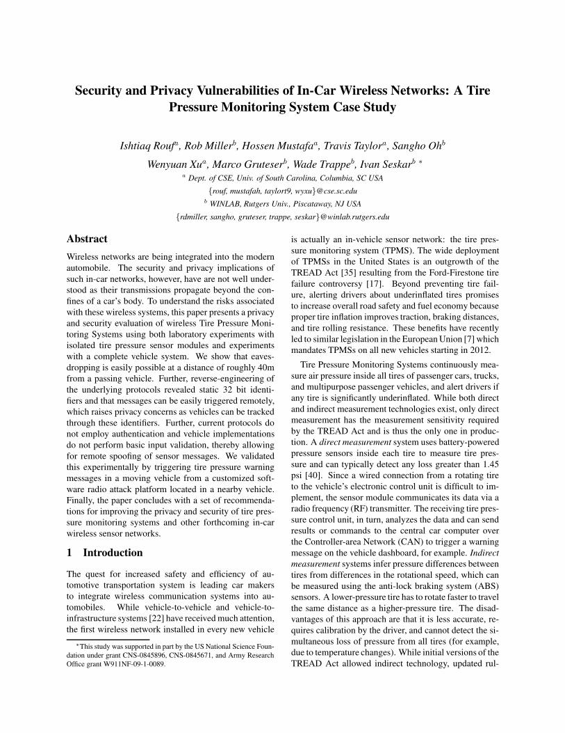
TPMS architecture. A typical direct TPMS containsthe following components: TPM sensors fitted into theback of the valve stem of each tire, a TPM electric con-trol unit (ECU), a receiving unit (either integrated withthe ECU or stand-alone), a dashboard TPM warninglight, and one or four antennas connected to the receivingunit. The TPM sensors periodically broadcast the pres-sure and temperature measurements together with their
ECU /Receiver
Pressuredisplay
WarningLamp TP sensor
Antenna
Dash panel
Figure 1: TPMS architecture with four antennas.
identifiers. The TPM ECU/receiver receives the pack-ets and performs the following operations before send-ing messages to the TPM warning light. First, since itcan receive packets from sensors belonging to neighbor-ing cars, it filters out those packets. Second, it performstemperature compensation, where it normalizes the pres-sure readings and evaluates tire pressure changes. Theexact design of the system differs across suppliers, par-ticularly in terms of antenna configuration and commu-nication protocols. A four-antenna configuration is nor-mally used in high-end car models, whereby an antennais mounted in each wheel housing behind the wheel archshell and connected to a receiving unit through high fre-quency antenna cables, as depicted in Figure 1. The four-antenna system prolongs sensor battery life, since the an-tennas are mounted close to the TPM sensors which re-duces the required sensor transmission power. However,to reduce automobile cost, the majority of car manufac-tories use one antenna, which is typically mounted on therear window [11, 39].Communication protocols. The communications pro-tocols used between sensors and TPM ECUs are propri-etary. From supplier websites and marketing materials,however, one learns that TPMS data transmissions com-monly use the 315 MHz or 433 MHz bands (UHF) andASK (Amplitude Shift Keying) or FSK (Frequency ShiftKeying) modulation. Each tire pressure sensor carries anidentifier (ID). Before the TPMS ECU can accept datareported by tire pressure sensors, IDs of the sensor andthe position of the wheel that it is mounted on have to beentered to the TPMS ECU either manually in most carsor automatically in some high-end cars. This is typicallydone during tire installation. Afterwards, the ID of thesensor becomes the key information that assists the ECUin determining the origin of the data packet and filteringout packets transmitted by other vehicles.
To prolong battery life, tire pressure sensors are de-signed to sleep most of the time and wake up in two sce-narios: (1) when the car starts to travel at high speeds(over 40 km/h), the sensors are required to monitor tire
3
pressures; (2) during diagnosis and the initial sensorID binding phases, the sensors are required to transmittheir IDs or other information to facilitate the procedures.Thus, the tire pressure sensors will wake up in responseto two triggering mechanisms: a speed higher than 40km/h detected by an on-board accelerometer or an RFactivation signal.
The RF activation signals operate at 125 kHz in thelow frequency (LF) radio frequency band and can onlywake up sensors within a short range, due to the gener-ally poor characteristics of RF antennas at that low fre-quency. According to manuals from different tire sen-sor manufacturers, the activation signal can be either atone or a modulated signal. In either case, the LF re-ceiver on the tire sensor filters the incoming activationsignal and wakes up the sensor only when a matchingsignal is recognized. Activation signals are mainly usedby car dealers to install and diagnose tire sensors, and aremanufacturer-specific.
2.1 Security and Privacy Analysis Goals
Our analysis will concentrate on tracking risks througheavesdropping on sensor identifiers and on messagespoofing risks to insert forged data in the vehicle ECU.The presence of an identifier raises the specter of lo-cation privacy concerns. If the sensor IDs were cap-tured at roadside tracking points and stored in databases,third parties could infer or prove that the driver has vis-ited potentially sensitive locations such as medical clin-ics, political meetings, or nightclubs. A similar exampleis seen with electronic toll records that are captured athighway entry and exit points by private entities for traf-fic monitoring purposes. In some states, these recordsare frequently subpoenaed for civil lawsuits. If trackingthrough the tire pressure monitoring system were pos-sible, this would create additional concerns, particularlybecause the system will soon be present in all cars andcannot easily be deactivated by a driver.
Besides these privacy risks, we will consider attackswhere an adversary interferes with the normal operationsof TPMS by actively injecting forged messages. For in-stance, an adversary could attempt to send a low pressurepacket to trigger a low pressure warning. Alternatively,the adversary could cycle through a few forged low pres-sure packets and a few normal pressure packets, causingthe low pressure warning lights to turn on and off. Suchattacks, if possible, could undermine drivers’ faith in thesystem and potentially lead them to ignore TPMS-relatedwarnings completely. Last but not least, since the TPMsensors always respond to the corresponding activationsignal, an adversary that continuously transmits activa-tion signals can force the tire sensors to send packetsconstantly, greatly reducing the lifetime of TPMS.
To evaluate the privacy and security risks of such asystem, we will address the issues listed below in thefollowing sections.
Difficulty of reverse engineering. Many potential at-tackers are unlikely to have access to insider in-formation and must therefore reconstruct the proto-cols, both to be able to extract IDs to track vehiclesand to spoof messages. The level of informationnecessary differs among attacks; replays for exam-ple might only require knowledge of the frequencyband but more sophisticated spoofing requires pro-tocol details. For spoofing attacks we also considerwhether off-the-shelf radios can generate and trans-mit the packets appropriately.
Identifier characteristics. Tracking requires observingidentifying characteristics from a message, so thatmultiple messages can be linked to the same vehi-cle. The success of tracking is closely tied to theanswers to: (1) Are the sensor IDs used temporar-ily or over long time intervals? (2) Does the lengthof the sensor ID suffice to uniquely identify a car?Since the sensor IDs are meant to primarily identifytheir positions in the car, they may not be globallyunique and may render tracking difficult.
Transmission range and frequency. Tracking furtherdepends on whether a road-side tracking unit will belikely to overhear a transmission from a car passingat high speed. This requires understanding the rangeand messaging frequency of packet transmissions.To avoid interference between cars and to prolongthe battery life, the transmission powers of the sen-sors are deliberately chosen to be low. Is it possibleto track vehicles with such low transmission powercombined with low messaging frequency?
Security measures. The ease of message spoofing de-pends on the use of security measures in TPMSs.The key questions to make message spoofing a prac-tical threat include: (1) Are messages authenti-cated? (2) Does the vehicle use consistency checksand filtering mechanisms to reject suspicious pack-ets? (3) How long, if possible, does it take the ECUto completely recover from a spoofing attack?
3 Reverse Engineering TPMS Communi-cation Protocols
Analyzing security and privacy risks begins with obtain-ing a thorough comprehension of the protocols for spe-cific sensor systems. To elaborate, one needs to knowthe modulation schemes, encoding schemes, and mes-sage formats, in addition to the activation and reporting
4

Figure 2: Equipment used for packet sniffing. At the bottom,from left to right are the ATEQ VT55 TPMS trigger tool, twotire pressure sensors (TPS-A and TPS-B), and a low noise am-plifier (LNA). At the top is one laptop connected with a USRPwith a TVRX daughterboard attached.
methodologies to properly decode or spoof sensor mes-sages. Apart from access to an insider or the actual spec-ifications, this information requires reverse-engineeringby an adversary. To convey the level of difficulty of thisprocess for in-car sensor protocols, we provide a briefwalk-through of our approach below, where we begin bypresenting relevant hardware.
Tire pressure sensor equipment. We selected tworepresentative tire pressure sensors that employ differentmodulation schemes. Both sensors are used in automo-biles with high market shares in the US. To prevent mis-use of the information here, we refer to these sensorssimply as tire pressure sensor A (TPS-A) and tire pres-sure sensor B (TPS-B). To help our process, we also ac-quired a TPMS trigger tool, which is available for a fewhundred dollars. Such tools are handheld devices thatcan activate and decode information from a variety oftire sensor implementations. These tools are commonlyused by car technicians and mechanics for troubleshoot-ing. For our experiments, we used a TPMS trigger toolfrom ATEQ [8] (ATEQ VT55).
Raw signal sniffer. Reverse engineering the TPMSprotocols requires the capture and analysis of raw sig-nal data. For this, we used GNU Radio [2] in con-junction with the Universal Software Radio Peripheral(USRP) [1]. GNU Radio is an open source, free softwaretoolkit that provides a library of signal processing blocksthat run on a host processing platform. Algorithms im-plemented using GNU Radio can receive data directlyfrom the USRP, which is the hardware that provides RFaccess via an assortment of daughterboards. They in-clude the TVRX daughterboard capable of receiving RFin the range of 50 Mhz to 870 MHz and the LFRX daugh-terboard able to receive from DC to 30 MHz. For con-venience, we initially used an Agilent 89600 Vector Sig-nal Analyzer (VSA) for data capture (but such equipment
is not necessary). The pressure sensor modules, triggertool, and software radio platform are shown in Figure 2.
3.1 Reverse Engineering Walk Through
While our public domain search resulted in only high-level knowledge about the TPM communication proto-col specifics, anticipating sensor activity in the 315/433MHz bands did provide us with a starting point for ourreverse engineering analysis.
We began by collecting a few transmissions from eachof the TPM sensors. The VSA was used to narrow downthe spectral bandwidth necessary for fully capturing thetransmissions. The sensors were placed close to the VSAreceiving antenna while we used the ATEQ VT55 to trig-ger the sensors. Although initial data collections wereobtained using the VSA, the research team switched tousing the USRP to illustrate that our findings (and subse-quently our attacks) can be achieved with low-cost hard-ware. An added benefit of using the USRP for the datacollections is that it is capable of providing synchronizedcollects for the LF and HF frequency bands — thus al-lowing us to extract important timing information be-tween the activation signals and the sensor responses. Toperform these collects, the TVRX and LFRX daughter-boards were used to provide access to the proper radiofrequencies. Once the sensor bursts were collected, webegan our signal analysis in MATLAB to understand themodulation and encoding schemes. The final step was tomap out the message format.
Determine coarse physical layer characteristics.The first phase of characterizing the sensors involvedmeasuring burst widths, bandwidth, and other physicallayer properties. We observed that burst widths wereon the order of 15 ms. During this initial analysis, wenoted that each sensor transmitted multiple bursts in re-sponse to their respective activation signals. TPS-A used4 bursts, while TPS-B responded with 5 bursts. Indi-vidual bursts in the series were determined to be exactcopies of each other, thus each burst encapsulates a com-plete sensor report.
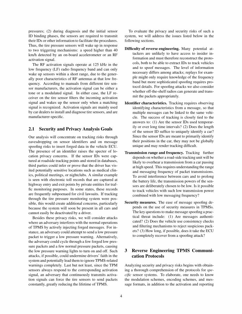
Identify the modulation scheme. Analysis of thebaseband waveforms revealed two distinct modulationschemes. TPS-A employed amplitude shift keying(ASK), while TPS-B employed a hybrid modulationscheme — simultaneous usage of ASK and frequencyshift keying (FSK). We speculate that the hybrid schemeis used for two reasons: (1) to maximize operability withTPM readers and (2) to mitigate the effects of an adversechannel during normal operation. Figure 3 illustrates thedifferences between the sensors’ transmission in both thetime and frequency domains. The modulation schemesare also observable in these plots.
5
−100 −50 0 50 100−80
−60
−40
−20
0
Frequency (KHz)
Mag
nitu
de (d
B)
TPS−A
−100 −50 0 50 100
−80
−60
−40
−20
0
Frequency (KHz)
TPS−B
2000 2100 2200 2300 2400
−1
−0.5
0
0.5
1
Sample Number
Nor
mal
ized
Mag
nitu
de
2000 2100 2200 2300 2400
−1
−0.5
0
0.5
1
Sample Number
Figure 3: A comparison of FFT and signal strength time seriesbetween TSP-A and TSP-B sensors.
Resolve the encoding scheme. Despite the differentmodulation schemes, it was immediately apparent thatboth sensors were utilizing Manchester encoding (afterdistinct preamble sequences). The baud rate is directlyobservable under Manchester encoding and was on theorder of 5 kBd. The next step was to determine the bitmappings from the Manchester encoded signal. In orderto accomplish this goal, we leveraged knowledge of aknown bit sequence in each message. We knew the sen-sor ID because it was printed on each sensor and assumedthat this bit sequence must be contained in the message.We found that applying differential Manchester decodinggenerated a bit sequence containing the sensor ID.
Reconstructing the message format. While bothsensors used differential Manchester encoding, theirpacket formats differed significantly. Thus, our next stepwas to determine the message mappings for the rest ofthe bits for each sensor. To understand the size and mean-ing of each bitfield, we manipulated sensor transmissionsby varying a single parameter and observed which bitschanged in the message. For instance, we adjusted thetemperature using hot guns and refrigerators, or adjustedthe pressure. By simultaneously using the ATEQ VT55,we were also able to observe the actual transmitted val-ues and correlate them with our decoded bits. Using thisapproach, we managed to determine the majority of mes-sage fields and their meanings for both TPS-A and TPS-B. These included temperature, pressure, and sensor ID,as illustrated in Figure 4. We also identified the use ofa CRC checksum and determined the CRC polynomialsthrough a brute force search.
At this point, we did not yet understand the meaningof a few bits in the message. We were later able to recon-struct these by generating messages with our software ra-dio, changing these bits, and observing the output of the
preamble Sensor ID Pressure Temperature Flags Checksum
Figure 4: An illustration of a packet format. Note the size isnot proportional to real packet fields.
TPMS tool or a real car. It turned out that these were pa-rameters like battery status, over which we had no directcontrol by purely manipulating the sensor module. Moredetails on message spoofing are presented in Section 5.
3.2 Lessons Learned
The aforementioned reverse-engineering can be accom-plished with a reasonable background in communica-tions and computer engineering. It took a few days fora PhD-level engineer experienced with reverse engineer-ing to build an initial system. It took several weeks for anMS-level student with no prior experience in reverse en-gineering and GNU Radio programming to understandand reproduce the attack. The equipment used (theVTEQ VT55 and USRP attached with TVRX) is openlyavailable and costs $1500 at current market prices.
Perhaps one of the most difficult issues involved baudrate estimation. Since Manchester encoding is used, ourinitial baud rate estimates involved averaging the gapsbetween the transition edges of the signal. However, thejitter (most likely associated with the local oscillators ofthe sensors) makes it almost impossible to estimate abaud rate accurate enough for a simple software-baseddecoder to work correctly. To address this problem, wemodified our decoders to be self-adjustable to compen-sate for the estimation errors throughout the burst.
The reverse engineering revealed the following obser-vations. First, it is evident that encryption has not beenused—which makes the system vulnerable to various at-tacks. Second, each message contains a 28-bit or 32-bitsensor ID depending on the type of sensor. Regardlessof the sensor type, the IDs do not change during the sen-sors’ lifetimes.
Given that there are 254.4 million registered passengervehicles in United States [34], one 28-bit Sensor ID isenough to track each registered car. Even in the futurewhen the number of cars may exceed 256 million, wecan still identify a car using a collection of tire IDs —a 4-tuple of tire IDs. Assuming a uniform distributionacross the 28-bit ID space, the probability of an exactmatch of two cars’ IDs is 4!/2112 without consideringthe ordering. To determine how many cars R can be onthe road in the US with a guarantee that there is a lessthan P chance of any two or more cars having the sameID-set, is a classical birthday problem calculation:
R =
√
2113
4!ln(
1
1 − P)
6

usrp_rx_cfile.py
pipeGnuRadio Packet
DetectorDemodclassifier
FSK Decoder
ASK Decoder
Temperature:xxpressure: xxSensor ID: xx
Temperature:xxpressure: xxSensor ID: xx
Figure 5: Block chart of the live decoder/eavesdropper.
To achieve a match rate of larger than P = 1%, morethan 1015 cars need to be on the road, which is signif-icantly more than 1 billion cars. This calculation, ofcourse, is predicated on the assumption of a uniform al-location across the 28-bit ID space. Even if we relax thisassumption and assume 20 bits of entropy in a single 28-bit ID space, we would still need roughly 38 billion carsin the US to get a match rate of more than P = 1%.
We note that this calculation is based on the unrealis-tic assumption that all 38 billion cars are co-located, andare using the same modulation and coding schemes. Ul-timately, it is very unlikely to have two cars that wouldbe falsely mistaken for each other.
4 Feasibility of Eavesdropping
A critical question for evaluating privacy implications ofin-car wireless networks is whether the transmissions canbe easily overheard from outside the vehicle body. Whiletire pressure data does not require strong confidentiality,the TPMS protocols contain identifiers that can be usedto track the locations of a device. In practice, the proba-bility that a transmission can be observed by a stationaryreceiver depends not only on the communication rangebut also on the messaging frequency and speed of thevehicle under observation, because these factors affectwhether a transmission occurs in communication range.
The transmission power of pressure sensors is rela-tively small to prolong sensor battery lifetime and reducecross-interference. Additionally, the NHTSA requirestire pressure sensors to transmit data only once every 60seconds to 90 seconds. The low transmission power, lowdata report rate, and high travel speeds of automobilesraise questions about the feasibility of eavesdropping.
In this section, we experimentally evaluate the rangeof TPMS communications and further evaluate the feasi-bility of tracking. This range study will use TPS-A sen-sors, since their TPMS uses a four-antenna structure andoperates at a lower transmission power. It should there-fore be more difficult to overhear.
4.1 Eavesdropping SystemDuring the reverse engineering steps, we developedtwo Matlab decoders: one for decoding ASK mod-ulated TPS-A and the other for decoding the FSK
modulated TPS-B. In order to reuse our decoders yetbe able to constantly monitor the channel and onlyrecord useful data using GNU radio together with theUSRP, we created a live decoder/eavesdropper leverag-ing pipes. We used the GNU Radio standard Pythonscript usrp rx cfile.py to sample channels at a rateof 250 kHz, where the recorded data was then piped to apacket detector. Once the packet detector identifies highenergy in the channel, it extracts the complete packet andpasses the corresponding data to the decoder to extractthe pressure, temperature, and the sensor ID. If decodingis successful, the sensor ID will be output to the screenand the raw packet signal along with the time stamp willbe stored for later analysis. To be able to capture datafrom multiple different TPMS systems, the eavesdrop-ping system would also need a modulation classifier torecognizes the modulation scheme and choose the corre-sponding decoder. For example, Liedtke’s [29] algorithmcould be used to differentiate ASK2 and FSK2. Such aneavesdropping system is depicted in Fig. 5.
In early experiments, we observed that the decodingscript generates much erratic data from interference andartifacts of the dynamic channel environment. To addressthis problem, we made the script more robust and addeda filter to discard erroneous data. This filter drops allsignals that do not match TPS-A or TPS-B. We havetested our live decoder on the interstate highway I-26(Columbia, South Carolina) with two cars running in par-allel at speeds exceeding 110 km/h.
4.2 Eavesdropping Range
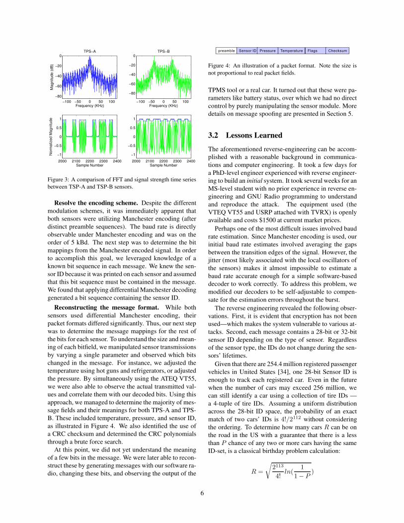
We measured the eavesdropping range in both indoor andoutdoor scenarios by having the ATEQ VT55 trigger thesensors. In both scenarios, we fixed the location of theUSRP at the origin (0, 0) in Figure 7 and moved thesensor along the y-axis. In the indoor environment, westudied the reception range of stand-alone sensors in ahallway. In the outdoor environment, we drove one ofthe authors’ cars around to measure the reception rangeof the sensors mounted in its front left wheel while thecar’s body was parallel to the x-axis, as shown in Fig-ure 7. In our experiment, we noticed that we were ableto decode the packets when the received signal strength islarger than the ambient noise floor. The resulting signalstrength over the area where packets could be decoded
7
Eavesdroppingrange
Indoornoise floor
Outdoornoise floor
Boostedrange
Amplifiednoise floor
Originalnoise floor
Originalrange
(a) indoor vs. outdoor (w/o LNA) (b) with LNA vs. without LNA (indoor)
Figure 6: Comparison of eavesdropping range of TPS-A.
successfully and the ambient noise floors are depictedin Figure 6 (a). The results show that both the outdoorand indoor eavesdropping ranges are roughly 10.7 m, thevehicle body appears only to have a minor attenuationeffect with regard to a receiver positioned broadside.
We next performed the same set of range experimentswhile installing a low noise amplifier (LNA) between theantenna and the USRP radio front end, as shown in Fig-ure 2. As indicated in Figure 6, the signal strength ofthe sensor transmissions still decreased with distance andthe noise floor was raised because of the LNA, but theLNA amplified the received signal strength and improvedthe decoding range from 10.7 meters to 40 meters. Thisshows that with some inexpensive hardware a significanteavesdropping range can be achieved, a range that allowssignals to be easily observed from the roadside.
Note that other ways to boost receiving range exist.Examples include the use of directional antennas or moresensitive omnidirectional antennas. We refer readers tothe antenna studies in [9,15,42] for further information.
4.3 Eavesdropping Angle StudyWe now investigate whether the car body has a largerattenuation effect if the receiver is located at differentangular positions. We also study whether one USRP isenough to sniff packets from all four tire sensors.
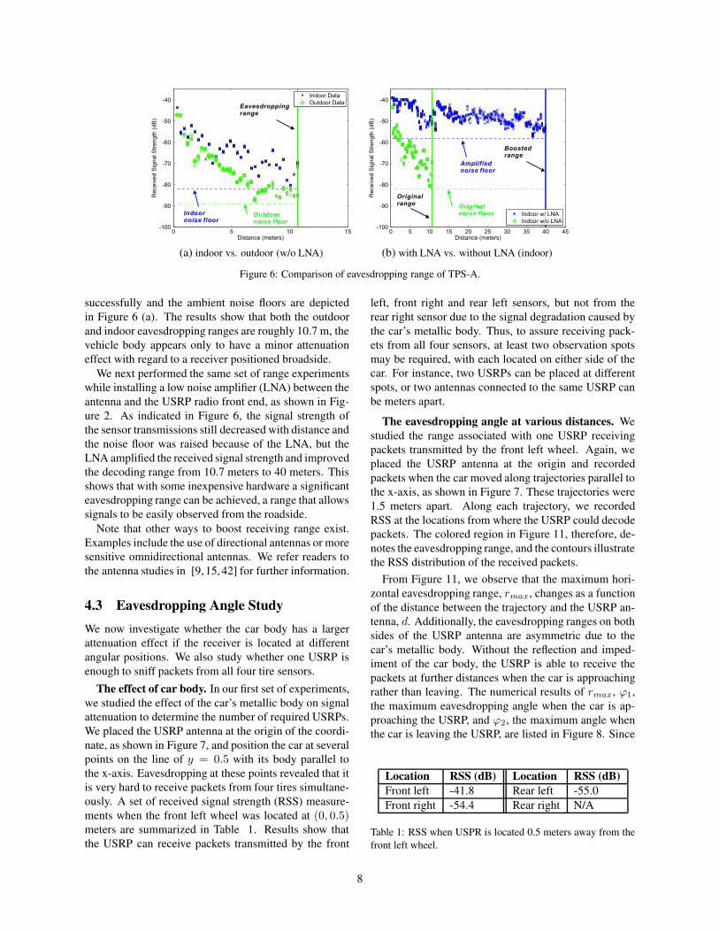
The effect of car body. In our first set of experiments,we studied the effect of the car’s metallic body on signalattenuation to determine the number of required USRPs.We placed the USRP antenna at the origin of the coordi-nate, as shown in Figure 7, and position the car at severalpoints on the line of y = 0.5 with its body parallel tothe x-axis. Eavesdropping at these points revealed that itis very hard to receive packets from four tires simultane-ously. A set of received signal strength (RSS) measure-ments when the front left wheel was located at (0, 0.5)meters are summarized in Table 1. Results show thatthe USRP can receive packets transmitted by the front
left, front right and rear left sensors, but not from therear right sensor due to the signal degradation caused bythe car’s metallic body. Thus, to assure receiving pack-ets from all four sensors, at least two observation spotsmay be required, with each located on either side of thecar. For instance, two USRPs can be placed at differentspots, or two antennas connected to the same USRP canbe meters apart.
The eavesdropping angle at various distances. Westudied the range associated with one USRP receivingpackets transmitted by the front left wheel. Again, weplaced the USRP antenna at the origin and recordedpackets when the car moved along trajectories parallel tothe x-axis, as shown in Figure 7. These trajectories were1.5 meters apart. Along each trajectory, we recordedRSS at the locations from where the USRP could decodepackets. The colored region in Figure 11, therefore, de-notes the eavesdropping range, and the contours illustratethe RSS distribution of the received packets.
From Figure 11, we observe that the maximum hori-zontal eavesdropping range, rmax, changes as a functionof the distance between the trajectory and the USRP an-tenna, d. Additionally, the eavesdropping ranges on bothsides of the USRP antenna are asymmetric due to thecar’s metallic body. Without the reflection and imped-iment of the car body, the USRP is able to receive thepackets at further distances when the car is approachingrather than leaving. The numerical results of rmax, ϕ1,the maximum eavesdropping angle when the car is ap-proaching the USRP, and ϕ2, the maximum angle whenthe car is leaving the USRP, are listed in Figure 8. Since
Location RSS (dB) Location RSS (dB)Front left -41.8 Rear left -55.0Front right -54.4 Rear right N/A
Table 1: RSS when USPR is located 0.5 meters away from thefront left wheel.
8

Y
X
φ1
φ2
rmax
d
0
Figure 7: The experiment setup for the range study.
the widest range of 9.1 meters at the parallel trajectorywas 3 meters away from the x-axis, an USRP should beplaced 2.5 meters away from the lane marks to maximizethe chance of packet reception, assuming cars travel 0.5meter away from lane marks.
Messaging rate. According to NHTSA regulations,TPMS sensors transmit pressure information every 60to 90 seconds. Our measurements confirmed that bothTPS-A and TPS-B sensors transmit one packet every 60seconds or so. Interestingly, contrary to documentation(where sensors should report data periodically after aspeed higher than 40 km/h), both sensors periodicallytransmit packet even when cars are stationary. Further-more, TPS-B transmits periodic packets even when thecar is not running.
4.4 Lessons Learned: Feasibility of Track-ing Automobiles
The surprising range of 40m makes it possible to capturea packet and its identifiers from the roadside, if the caris stationary (e.g., a traffic light or a parking lot). Giventhat a TPMS sensor only send one message per minute,tracking becomes difficult at higher speeds. Consider, forexample, a passive tracking system deployed along theroadside at highway entry and exit ramps, which seeksto extract the unique sensor ID for each car and link en-try and exit locations as well as subsequent trips. To en-sure capturing at least one packet, a row of sniffers wouldbe required to cover the stretch of road that takes a car60 seconds to travel. The number of required sniffers,npassive = ceil(v ∗ T/rmax), where v is the speed ofthe vehicle, T is the message report period, and rmax isthe detection range of the sniffer. Using the sniffing sys-tem described in previous sections where rmax = 9.1m, 110 sniffers are required to guarantee capturing onepacket transmitted by a car traveling at 60 km/h. De-ploying such a tracking system appears cost-prohibitive.
It is possible to track with fewer sniffers, however, byleveraging the activation signal. The tracking station cansend the 125kHz activation signal to trigger a transmis-sion by the sensor. To achieve this, the triggers and snif-
x (meters) (dB)
y (m
eter
s)
−3 −2 −1 0 1 2 3 4 5
2
3
4
5
6
7
−56
−55
−54
−53
−52
−51
−50
−49
−48
−47
Figure 11: Study the angle of eavesdropping with LNA.
fers should be deployed in a way such that they meetthe following requirements regardless of the cars’ travelspeeds: (1) the transmission range of the trigger shouldbe large enough so that the passing car is able to receivethe complete activation signal; (2) the sniffer should beplaced at a distance from the activation sender so that thecar is in the sniffers’ eavesdropping range when it startsto transmit; and (3) the car should stay within the eaves-dropping range before it finishes the transmission.
To determine the configuration of the sniffers and thetriggers, we conducted an epitomical study using a USRPwith two daughterboards attached, one recording at 125kHz and the other recording at 315 MHz. Our resultsare depicted in Figure 9 and show that the activation sig-nal of TPS-B lasts approximately 359 ms. The sensorsstart to transmit 530 ms after the beginning of the acti-vation signal, and the data takes 15 ms to transmit. Thismeans, that to trigger a car traveling at 60 km/h, the trig-ger should have a transmission range of at least 6 meters.Since a sniffer can eavesdrop up to 9.1 meters, it sufficesto place the sniffer right next to the trigger. Additionalsniffers could be placed down the road to capture pack-ets of cars traveling at higher speeds.
To determine the feasibility of this approach, we haveconducted a roadside experiment using the ATEQ VT55which has a transmission range of 0.5 meters. We wereable to activate and extract the ID of a targeted TPMSsensor moving at the speed of 35 km/h using one sniffer.We note that ATEQ VT55 was deliberately designed withshort transmission range to avoid activating multiple carsin the dealership. With a different radio frontend, such asusing a matching antenna for 125 kHz, one can increasethe transmission range of the trigger easily and enablecapturing packets from cars at higher speeds.
Comparison between tracking via TPMS and Au-tomatic Number Plate Reading. Automatic NumberPlate Reading (ANPR) technologies have been proposedto track automobiles and leverage License Plate Cap-ture Cameras (LPCC) to recognize license plate num-bers. Due to the difference between underlying technolo-
9

d (m) ϕ1 (◦) ϕ2(◦) rmax (m)1.5 72.8 66.8 8.53.0 59.1 52.4 9.14.5 45.3 31.8 7.56.0 33.1 20.7 6.37.5 19.6 7.7 3.8
Figure 8: The eavesdropping angles andranges when the car is traveling at varioustrajectories.
0 0.2 0.4 0.6 0.8 1 1.2 1.40
0.5
1
Time (seconds)
Nor
mal
ized
Mag
nitu
de
ActivationData
Figure 9: Time series of activation anddata signals.
Figure 10: Frequency mixer and USRPwith two daughterboards are used totransmit data packets at 315/433 MHz.
gies, TPMS and ANPR systems exhibit different charac-teristics. First, ANPR allows for more direct linkage toindividuals through law enforcement databases. ANPRrequires, however, line of sight (LOS) and its accuracycan be affected by weather conditions (e.g. light or hu-midity) or the dirt on the plate. In an ideal condition withexcellent modern systems, the read rate for license platesis approximately 90% [25]. A good quality ANPR cam-era can recognize number plates at 10 meters [5]. Onthe contrary, the ability to eavesdrop on the RF transmis-sion of TPMS packets does not depend on illuminationor LOS. The probability of identifying the sensor ID isaround 99% when the eavesdropper is placed 2.5 metersaway from the lane marks. Second, the LOS require-ment forces the ANPR to be installed in visible locations.Thus, a motivated driver can take alternative routes or re-move/cover the license plates to avoid being detected. Incomparison, the use of TPMS is harder to circumvent,and the ability to eavesdrop without LOS could lead tomore pervasive automobile tracking. Although swappingor hiding license plates requires less technical sophistica-tion, it also imposes much higher legal risks than deacti-vating TPMS units.
5 Feasibility of Packet Spoofing
Being able to eavesdrop on TPMS communication froma distance allows us to further explore the feasibility ofinserting forged data into safety-critical in-vehicle sys-tems. Such a threat presents potentially even greaterrisks than the tracking risks discussed so far. Whilethe TPMS is not yet a highly safety-critical system, weexperimented with spoofing attacks to understand: (1)whether the receiver sensitivity of an in-car radio is highenough to allow spoofing from outside the vehicle or aneighboring vehicle, and (2) security mechanisms andpractices in such systems. In particular, we were curiouswhether the system uses authentication, input validation,or filtering mechanisms to reject suspicious packets.
The packet spoofing system. Our live eavesdrop-per can detect TPMS transmission and decode both ASK
modulated TPS-A messages and FSK modulated TPS-B messages in real time. Our packet spoofing system isbuilt on top of our live eavesdropper, as shown in Fig-ure 12. The Packet Generator takes two sets of parame-ters —sensor type and sensor ID from the eavesdropper;temperature, pressure, and status flags from users—andgenerates a properly formulated message. It then modu-lates the message at baseband (using ASK or FSK) whileinserting the proper preamble. Finally, the rogue sensorpackets are upconverted and transmitted (either contin-uously or just once) at the desired frequency (315/433MHz) using a customized GNU radio python script. Wenote that once the sensor ID and sensor type are capturedwe can create and repeatedly transmit the forged messageat a pre-defined period.
At the time of our experimentation, there were noUSRP daughterboards available that were capable oftransmitting at 315/433 MHz. So, we used a frequencymixing approach where we leveraged two XCVR2450daughterboards and a frequency mixer (mini-circuitsZLW11H) as depicted in Fig.10. By transmitting a toneout of one XCVR2450 into the LO port of the mixer,we were able to mix down the spoofed packet from theother XCVR2450 to the appropriate frequency. For 315MHz, we used a tone at 5.0 GHz and the spoofed packetat 5.315 GHz.1
To validate our system, we decoded spoofed packetswith the TPMS trigger tool. Figure 13 shows a screensnapshot of the ATEQ VT55 after receiving a spoofedpacket with a sensor ID of “DEADBEEF” and a tire pres-sure of 0 PSI. This testing also allowed us to understandthe meaning of remaining status flags in the protocol.
5.1 Exploring Vehicle Security
We next used this setup to send various forged packetsto a car using TPS-A sensors (belonging to one of the
1For 433 MHz, the spoofed packet was transmitted at 5.433 GHz.We have also successfully conducted the experiment using two RFX-1800 daughterboards, whose operational frequencies are from 1.5 GHzto 2.1 GHz.
10

Eavesdropper PacketGenerator
SensorID
SensorType
USRP Tx
GnuRadio
Figure 12: Block chart of the packet spoofing system.
authors) at a rate of 40 packets per second. We made thefollowing observations.
No authentication. The vehicle ECU ignores packetswith a sensor ID that does not match one of the knownIDs of its tires, but appears to accept all other packets.For example, we transmitted forged packets with the IDof the left front tire and a pressure of 0 PSI and found 0PSI immediately reflected on the dashboard tire pressuredisplay. By transmitting messages with the alert bit setwe were able to immediately illuminate the low-pressurewarning light2, and with about 2 seconds delay the ve-hicle’s general-information warning light, as shown inFigure 14.
No input validation and weak filtering. We forgedpackets at a rate of 40 packets per second. Neither thisincreased rate, nor the occasional different reports bythe real tire pressure sensor seemed to raise any suspi-cion in the ECU or any alert that something was wrong.The dashboard simply displayed the spoofed tire pres-sure. We next transmitted two packets with very differ-ent pressure values alternately at a rate of 40 packets persecond. The dashboard display appeared to randomlyalternate between these values. Similarly, when alter-nating between packets with and without the alert flag,we observed the warning lights switched on and off atnon-deterministic time intervals. Occasionally, the dis-play seemed to freeze on one value. These observationssuggest that TPMS ECU employs trivial filtering mecha-nisms which can be easily confused by spoofed packets.
Interestingly, the illumination of the low-pressurewarning light depends only on the alert bit—the lightturns on even if the rest of the message reports a nor-mal tire pressure of 32 PSI! This further illustrates thatthe ECU does not appear to use any input validation.
Large range of attacks. We first investigated theeffectiveness of packet spoofing when vehicles are sta-tionary. We measured the attack range when the packetspoofing system was angled towards the head of the car,and we observed a packet spoofing range of 38 meters.For the purpose of proving the concept, we only usedlow-cost antennas and radio devices in our experiments.We believe that the range of packet spoofing can begreatly expanded by applying amplifiers, high-gain an-tennas, or antenna arrays.
2To discover this bit we had to deflate one tire and observe the tirepressure sensors response. Simply setting a low pressure bit or report-ing low pressure values did not trigger any alert in the vehicle.
Feasibility of Inter-Vehicle Spoofing. We deployedthe attacks against willing participants on highway I-26to determine if they are viable at high speeds. Two carsowned by the authors were involved in the experiment.The victim car had TPS-A sensors installed and the at-tacker’s car was equipped with our packet spoofing sys-tem. Throughout our experiment, we transmitted alertpackets using the front-left-tire ID of the target car, whilethe victim car was traveling to the right of the attacker’scar. We observed that the attacker was able to triggerboth the low-pressure warning light and the car’s central-warning light on the victim’s car when traveling at 55km/h and 110 km/h, respectively. Additionally, the low-pressure-warning light illuminated immediately after theattacker entered the packet spoofing range.
5.2 Exploring the Logic of ECU Filtering
Forging a TPMS packet and transmitting it at a high rateof 40 packets per second was useful to validate packetspoofing attacks and to gauge the spoofing range. Be-yond this, though, it was unclear whether there were fur-ther vulnerabilities in the ECU logic. To characterize thelogic of the ECU filtering mechanisms, we designed avariety of spoofing attacks. The key questions to be an-swered include: (1) what is the minimum requirement totrigger the TPMS warning light once, (2) what is the min-imum requirement to keep the TPMS warning light onfor an extended amount of time, and (3) can we perma-nently illuminate any warning light even after stoppingthe spoofing attack?
So far, we have observed two levels of warning lights:TPMS Low-Pressure Warning light (TPMS-LPW) andthe vehicle’s general-information warning light illustrat-ing ‘Check Tire Pressure’. In this section, we exploredthe logic of filtering strategies related to the TPMS-LPW light in detail. The logic controlling the vehicle’sgeneral-information warning light can be explored in asimilar manner.
5.2.1 Triggering the TPMS-LPW Light
To understand the minimum requirement of triggeringthe TPMS-LPW light, we started with transmitting onespoofed packet with the rear-left-tire ID and eavesdrop-ping the entire transmission. We observed that (1) onespoofed packet was not sufficient to trigger the TPMS-LPW light; and (2) as a response to this packet, theTPMS ECU immediately sent two activation signalsthrough the antenna mounted close to the rear left tire,causing the rear left sensor to transmit eight packets.Hence, although a single spoofed packet does not causethe ECU to display any warning, it does open a vulnera-bility to battery drain attacks.
11

Figure 13: The TPMS trigger tool dis-plays the spoofed packet with the sen-sor ID “DEADBEEF”. We crossed outthe brand of TP sensors to avoid legalissues.
(a) (b)
Figure 14: Dash panel snapshots: (a) the tire pressure of left front tire displayedas 0 PSI and the low tire pressure warning light was illuminated immediately aftersending spoofed alert packets with 0 PSI; (b) the car computer turned on the generalwarning light around 2 seconds after keeping sending spoofed packets.
Next, we gradually increased the number of spoofedpackets, and we found that transmitting four spoofedpackets in one second suffices to illuminate the TPMS-LPW light. Additionally, we found that those fourspoofed packets have to be at least 225 ms apart, oth-erwise multiple spoofed packets will be counted as one.When the interval between two consecutive spoofedpackets is larger than 4 seconds or so, the TPMS-LPWno longer illuminates. This indicates that TPMS adoptstwo detection windows with sizes of 240 ms (a packetlasts for 15 ms) and 4 seconds. A 240-ms window isconsidered positive for low tire pressure if at least onelow-pressure packet has been received in that windowregardless of the presence of numerous normal packets.Four 240-ms windows need to be positive to illuminatethe TPMS-LPW light. However, the counter for positive240-ms windows will be reset if no low-pressure packetis received within a 4-s window.
Although the TPMS ECU does use a counting thresh-old and window-based detection strategies, they are de-signed to cope with occasionally corrupted packets in abenign situation and are unable to deal with maliciousspoofing. Surprisingly, although the TPMS ECU doesreceive eight normal packets transmitted by sensors asa response to its queries, it still concludes the low-tire-pressure status based on one forged packet, ignoring themajority of normal packets!
5.2.2 Repeatedly Triggering the TPMS-LPW Light
The TPMS-LPW light turns off a few seconds if onlyfour forged packets are received. To understand howto sustain the warning light, we repeatedly transmittedspoofed packets and increased the spoofing period grad-ually. The TPMS-LPW light remained illuminated whenwe transmitted the low-pressure packet at a rate higherthan one packet per 240 ms, e.g., one packet per detectionwindow. Spoofing at a rate between one packet per 240ms to 4 seconds caused the TPMS-LPW light to togglebetween on and off. However, spoofing at a rate slowerthan 4 seconds could not activate the TPMS-LPW light,
which confirmed our prior experiment results. Figure 15depicts the measured TPMS-LPW light on-durations andoff-durations when the spoofing periods increased from44 ms to 4 seconds.
As we increased the spoofing period, the TPMS-LPWlight remained on for about 6 seconds on average, butthe TPMS-LPW light stayed off for an incrementingamount of time which was proportional to the spoofingperiod. Therefore, it is very likely that the TPMS-ECUadopts a timer to control the minimum on-duration andthe off-duration of TPMS-LPW light can be modeled astoff = 3.5x + 4, where x is the spoofing period. Theoff-duration includes the amount of time to observe fourlow-pressure forged messages plus the minimum waitingduration for the TPMS-ECU to remain off, e.g., 4 sec-onds. In fact, this confirms our observation that there isa waiting period of approximately 4 seconds before theTPMS warning light was first illuminated.
5.2.3 Beyond Triggering the TPMS-LPW Light
Our previous spoofing attacks demonstrated that we canproduce false TPMS-LPW warnings. In fact, transmit-ting forged packets at a rate higher than one packet persecond also triggered the vehicle’s general-informationwarning light illustrating ‘Check Tire Pressure’. De-pending on the spoofing period, the gap between theillumination of the TPMS-LPW light and the vehicle’sgeneral-information warning light varied between a fewseconds to 130 seconds — and the TPMS-LPW light re-mained illuminated afterwards.
Throughout our experiments, we typically exposed thecar to spoofed packets for a duration of several minutes ata time. While the TPMS-LPW light usually disappearedabout 6 seconds after stopping spoofed message trans-missions, we were once unable to reset the light even byturning off and restarting the ignition. It did, however,reset after about 10 minutes of driving.
To our surprise, at the end of only two days of spo-radic experiments involving triggering the TPMS warn-ing on and off, we managed to crash the TPMS ECU and
12

0 1 2 3 40
5
10
15
20
25
Spoofing period (s)
Dur
atio
n of
das
hboa
rd d
ispl
ay (s
)
Warning OnWarning Off
Figure 15: TPMS low-pressure warning light on and off dura-tion vs. spoofing periods.
completely disabled the service. The vehicle’s general-information warning light illustrating ‘Check TPMS Sys-tem’ was activated and no tire pressure information wasdisplayed on the dashboard, as shown in Figure 16. Weattempted to reset the system by sending good packets,restarting the car, driving on the highway for hours, andunplugging the car battery. None of these endeavorswere successful. Eventually, a visit to a dealership recov-ered the system at the cost of replacing the TPMS ECU.This incident suggests that it may be feasible to crash theentire TPMS and the degree of such an attack can be sosevere that the owner has no option but to seek the ser-vices of a dealership. We note that one can easily explorethe logic of a vehicle’s general-information warning lightusing similar methods for TPMS-LPW light. We did notpursue further analysis due to the prohibitive cost of re-pairing the TPMS ECU.
5.3 Lessons Learned
The successful implementation of a series of spoofing at-tacks revealed that the ECU relies on sensor IDs to filterpackets, and the implemented filter mechanisms are noteffective in rejecting packets with conflicting informa-tion or abnormal packets transmitted at extremely highrates. In fact, the current filer mechanisms introduce se-curity risks. For instance, the TPMS ECU will triggerthe sensors to transmit several packets after receiving onespoofed message. Those packets, however, are not lever-aged to detect conflicts and instead can be exploited tolaunch battery drain attacks. In summary, the absence ofauthentication mechanisms and weak filter mechanismsopen many loopholes for adversaries to explore for more‘creative’ attacks. Furthermore, despite the unavailabil-ity of a radio frontend that can transmit at 315/433 MHz,we managed to launch the spoofing attack using a fre-quency mixer. This result is both encouraging and alarm-ing since it shows that an adversary can spoof packetseven without easy access to transceivers that operate atthe target frequency band.
(a) (b)
Figure 16: Dash panel snapshots indicating the TPMS systemerror (this error cannot be reset without the help of a dealer-ship): (a) the vehicle’s general-information warning light; (b)tire pressure readings are no longer displayed as a result of sys-tem function errors.
6 Protecting TPMS Systems from Attacks
There are several steps that can improve the TPMS de-pendability and security. Some of the problems arisefrom poor system design, while other issues are tied tothe lack of cryptographic mechanisms.
6.1 Reliable Software Design
The first recommendation that we make is that softwarerunning on TPMS should follow basic reliable softwaredesign practices. In particular, we have observed that itwas possible to convince the TPMS control unit to dis-play readings that were clearly impossible. For example,the TPMS packet format includes a field for tire pressureas well as a separate field for warning flags related to tirepressure. Unfortunately, the relationship between thesefields were not checked by the TPMS ECU when pro-cessing communications from the sensors. As noted ear-lier, we were able to send a packet containing a legitimatetire pressure value while also containing a low tire pres-sure warning flag. The result was that the driver’s dis-play indicated that the tire had low pressure even thoughits pressure was normal. A straight forward fix for thisproblem (and other similar problems) would be to updatethe software on the TPMS control unit to perform con-sistency checks between the values in the data fields andthe warning flags. Similarly, when launching messagespoofing attacks, although the control unit does querysensors to confirm the low pressure, it neglects the le-gitimate packet responses completely. The control unitcould have employed some detection mechanism to, atleast, raise an alarm when detecting frequent conflictinginformation, or have enforced some majority logic oper-ations to filter out suspicious transmissions.
6.2 Improving Data Packet Format
One fundamental reason that eavesdropping and spoof-ing attacks are feasible in TPMS systems is that packetsare transmitted in plaintext. To prevent these attacks, a
13

first line of defense is to encrypt TPM packets3. The ba-sic packet format in a TPMS system included a sensor IDfield, fields for temperature and tire pressure, fields forvarious warning flags, and a checksum. Unfortunately,the current packet format used is ill-suited for proper en-cryption, since naively encrypting the current packet for-mat would still support dictionary-based cryptanalysis aswell as replay attacks against the system. For this reason,we recommend that an additional sequence number fieldbe added to the packet to ensure freshness of a packet.Further, requiring that the sequence number field be in-cremented during each transmission would ensure thatsubsequent encrypted packets from the same source be-come indistinguishable, thereby making eavesdroppingand cryptanalysis significantly harder. We also recom-mend that an additional cryptographic checksum (e.g. amessage authentication code) be placed prior to the CRCchecksum to prevent message forgery.
Such a change in the payload would require thatTPMS sensors have a small amount memory in order tostore cryptographic keys, as well as the ability to performencryption. An obvious concern is the selection of cryp-tographic algorithms that are sufficiently light-weight tobe implemented on the simple processor within a TPMSsensor, yet also resistant to cryptanalysis. A secondaryconcern is the installation of cryptographic keys. We en-vision that the sensors within a tire would be have keyspre-installed, and that the corresponding keys could beentered into the ECU at the factory, dealership, or a cer-tified garage. Although it is unlikely that encryption andauthentication keys would need to be changed, it wouldbe a simple matter to piggy-back a rekeying commandon the 125kHz activation signal in a manner that onlycertified entities could update keys.
6.3 Preventing Spoofed ActivationThe spoofing of an activation signal forces sensors toemit packets and facilitates tracking and battery drain at-tacks. Although activation signals are very simple, theycan convey a minimal amount of bits. Thus, using a longpacket format with encryption and authentication is un-suitable, and instead we suggest that the few bits they canconvey be used as a sequencing field, where the sequenc-ing follows a one-way function chain in a manner anal-ogous to one-time signatures. Thus, the ECU would beresponsible for maintaining the one-way function chain,and the TPMS sensor would simply hash the observedsequence number and compare with the previous se-quence number. This would provide a simple means offiltering out false activation signals. We note that other
3We note that encrypting the entire message (or at least all fieldsthat are not constant across different cars) is essential as otherwise theability to read these fields would support a privacy breach.
legitimate sources of activation signals are specializedentities, such as dealers and garages, and such entitiescould access an ECU to acquire the position within thehash chain in order to reset their activation units appro-priately to allow them to send valid activation signals.
7 Related Work
Wireless devices have become an inseparable part of oursocial fabric. As such, much effort has been dedicatedto analyze the their privacy and security issues. Devicesbeing studied include RFID systems [27, 30, 41], mass-market UbiComp devices [38], household robots [14],and implantable medical devices [21]. Although ourwork falls in the same category and complements thoseworks, TPMS in automobiles exhibits distinctive featureswith regard to the radio propagation environment (strongreflection within and off metal car bodies), ease of accessby adversaries (cars are left unattended in public), spanof usage, a tight linkage to the owners, etc. All thesecharacteristics have motivated this in-depth study on thesecurity and privacy of TPMS.
One related area of research is location privacy inwireless networks, which has attracted much attentionsince wireless devices are known to present trackingrisks through explicit identifiers in protocols or identi-fiable patterns in waveforms. In the area of WLAN,Brik et al. have shown the possibility to identify usersby monitoring radiometric signatures [10]. Gruteser etal. [19] demonstrated that one can identify a user’s loca-tion through link- and application-layer information. Acommon countermeasure against breaching location pri-vacy is to frequently dispose user identity. For instance,Jiang et al. [24] proposed a pseudonym scheme whereusers change MAC addresses each session. Similarly,Greenstein et al. [18] have suggested an identifier-freemechanism to protect user identities, whereby users canchange addresses for each packet.
In cellular systems, Lee et al. have shown that the lo-cation information of roaming users can be released tothird parties [28], and proposed using the temporary mo-bile subscriber identifier to cope with the location privacyconcern. IPv6 also has privacy concerns caused by thefixed portion of the address [32], and thus the use of peri-odically varying pseudo-random addresses has been rec-ommended. The use of pseudonyms is not sufficient toprevent automobile tracking since the sensors report tirepressure and temperature readings, which can be usedto build a signature of the car. Furthermore, pseudonymscannot defend against packet spoofing attacks such as wehave examined in this paper.
Security and privacy in wireless sensor networks havebeen studied extensively. Perrig et al. [37] have proposeda suite of security protocols to provide data confidential-
14

ity and authentication for resource-constrained sensors.Random key predistribution schemes [12] have been pro-posed to establish pairwise keys between sensors on de-mand. Those key management schemes cannot workwell with TPMS, since sensor networks are concernedwith establishing keys among a large number of sensorswhile the TPMS focuses on establishing keys betweenfour sensors and the ECU only.
Lastly, we note related work on the security of a car’scomputer system [26]. Their work involved analyzingthe computer security within a car by directly mountinga malicious component into a car’s internal network viathe On Broad Diagnostics (OBD) port (typically underthe dash board), and differs from our work in that wewere able to remotely affect an automobile’s security atdistances of 40 meters without entering the car at all.
8 Concluding Remarks
Tire Pressure Monitoring Systems (TPMS) are the firstin-car wireless network to be integrated into all new carsin the US and will soon be deployed in the EU. This pa-per has evaluated the privacy and security implicationsof TPMS by experimentally evaluating two representa-tive tire pressure monitoring systems. Our study revealedseveral security and privacy concerns. First, we reverseengineered the protocols using the GNU Radio in con-junction with the Universal Software Radio Peripheral(USRP) and found that: (i) the TPMS does not employany cryptographic mechanisms and (ii) transmits a fixedsensor ID in each packet, which raises the possibility oftracking vehicles through these identifiers. Sensor trans-missions can be triggered from roadside stations throughan activation signal. We further found that neither theheavy shielding from the metallic car body nor the low-power transmission has reduced the range of eavesdrop-ping sufficiently to reduce eavesdropping concerns. Infact, TPMS packets can be intercepted up to 40 metersfrom a passing car using the GNU Radio platform with alow-cost, low-noise amplifier. We note that the eaves-dropping range could be further increased with direc-tional antennas, for example.
We also found out that current implementations donot appear to follow basic security practices. Messagesare not authenticated and the vehicle ECU also does notappear to use input validation. We were able to injectspoofed messages and illuminate the low tire pressurewarning lights on a car traveling at highway speeds fromanother nearby car, and managed to disable the TPMSECU by leveraging packet spoofing to repeatedly turn onand off warning lights.
Finally, we have recommended security mechanismsthat can alleviate the security and privacy concerns pre-sented without unduly complicating the installation of
new tires. The recommendations include standard reli-able software design practices and basic cryptographicrecommendations. We believe that our analysis and rec-ommendations on TPMS can provide guidance towardsdesigning more secure in-car wireless networks.
References
[1] Ettus Research LLC. http://www.ettus.com/.
[2] GNU radio. http://gnuradio.org.
[3] IEEE 1609: Family of Standards for Wire-less Access in Vehicular Environments (WAVE).http://www.standards.its.dot.gov/fact sheet.asp?f=80.
[4] Portable, solar-powered tag readers couldimprove traffic management. Available athttp://news.rpi.edu/update.do?artcenterkey=1828.
[5] RE-BCC7Y Number plate recognition cameras.http://www.dsecctv.com/Prod lettura targhe.htm.
[6] Traffic hackers hit red light. Available athttp://www.wired.com/science/discoveries/news/2005/08/68507.
[7] Improving the safety and environmental performance ofvehicles. EUROPA-Press Releases (23rd May 2008).
[8] ATEQ VT55. http://www.tpms-tool.com/tpms-tool-ateqvt55.php.
[9] BALANIS, C., AND IOANNIDES, P. Introduction to smartantennas. Synthesis Lectures on Antennas 2, 1 (2007), 1–175.
[10] BRIK, V., BANERJEE, S., GRUTESER, M., AND OH,S. Wireless device identification with radiometric sig-natures. In Proceedings of ACM International Confer-ence on Mobile Computing and Networking (MobiCom)(2008), ACM, pp. 116–127.
[11] BRZESKA, M., AND CHAKAM, B. RF modelling andcharacterization of a tyre pressure monitoring system. InEuCAP 2007: The Second European Conference on An-tennas and Propagation (2007), pp. 1 – 6.
[12] CHAN, H., PERRIG, A., AND SONG, D. Random keypredistribution schemes for sensor networks. In SP ’03:Proceedings of the 2003 IEEE Symposium on Securityand Privacy (2003), IEEE Computer Society, p. 197.
[13] COLE, G., AND SHERMAN, A. Lightweight materialsfor automotive applications. Materials Characterization35 (1995), 3–9.
[14] DENNING, T., MATUSZEK, C., KOSCHER, K., SMITH,J. R., AND KOHNO, T. A spotlight on security andprivacy risks with future household robots: attacks andlessons. In Ubicomp ’09: Proceedings of the 11th in-ternational conference on Ubiquitous computing (2009),pp. 105–114.
[15] FERESIDIS, A., AND VARDAXOGLOU, J. High gainplanar antenna using optimised partially reflective sur-faces. In IEEE Proceedings on Microwaves, Antennasand Propagation (2001), vol. 148, pp. 345 – 350.
15

[16] FREDRIKSSON, L., AND AB, K.Bluetooth in automotive applications.http://www.kvaser.com/can/info/files/bluetooth-in-automotive-appl.pdf .
[17] GOVINDJEE, S. Firestone tire failure analysis, 2001.
[18] GREENSTEIN, B., MCCOY, D., PANG, J., KOHNO, T.,SESHAN, S., AND WETHERALL, D. Improving wire-less privacy with an identifier-free link layer protocol. InProceeding of Mobile systems, applications, and services(MobiSys) (2008), ACM, pp. 40–53.
[19] GRUTESER, M., AND GRUNWALD, D. A method-ological assessment of location privacy risks in wirelesshotspot networks. In Security in Pervasive Computing,First International Conference (2003), pp. 10–24.
[20] GRUTESER, M., AND GRUNWALD, D. Enhancing loca-tion privacy in wireless lan through disposable interfaceidentifiers: a quantitative analysis. ACM Mobile Networksand Applications (MONET) 10, 3 (2005), 315–325.
[21] HALPERIN, D., HEYDT-BENJAMIN, T. S., RANSFORD,B., CLARK, S. S., DEFEND, B., MORGAN, W., FU,K., KOHNO, T., AND MAISEL, W. H. Pacemakers andimplantable cardiac defibrillators: Software radio attacksand zero-power defenses. In Proceedings of IEEE Sym-posium on Security and Privacy (2008), IEEE ComputerSociety, pp. 129–142.
[22] IEEE 802.11P. IEEE draft standard for information tech-nology -telecommunications and information exchangebetween systems. http://www.ieee802.org/11/.
[23] ITALY. http://aglobalworld.com/international-countries/Europe/Italy.php.
[24] JIANG, T., WANG, H. J., AND HU, Y.-C. Preserving lo-cation privacy in wireless lans. In MobiSys ’07: Proceed-ings of the 5th international conference on Mobile sys-tems, applications and services (2007), ACM, pp. 246–257.
[25] KEILTHY, L. Measuring ANPR System Performance.Parking Trend International (2008).
[26] KOSCHER, K., CZESKIS, A., ROESNER, F., PATEL, S.,KOHNO, T., CHECKOWAY, S., MCCOY, D., KANTOR,B., ANDERSON, D., SHACHAM, H., AND SAVAGE, S.Experimental security analysis of a modern automobile.In Proceedings of IEEE Symposium on Security and Pri-vacy in Oakland (May 2010).
[27] KOSCHER, K., JUELS, A., BRAJKOVIC, V., AND
KOHNO, T. EPC RFID tag security weaknesses and de-fenses: passport cards, enhanced drivers licenses, and be-yond. In Proceedings of the 16th ACM conference onComputer and communications security (2009), pp. 33–42.
[28] LEE, C.-H., HWANG, M.-S., AND YANG, W.-P. En-hanced privacy and authentication for the global systemfor mobile communications. Wireless Networks 5, 4(1999), 231–243.
[29] LIEDTKE, F. Computer simulation of an automatic clas-sification procedure for digitally modulated communica-tion signals with unknown parameters. Signal Processing6 (1984), 311–323.
[30] MOLNAR, D., AND WAGNER, D. Privacy and securityin library RFID: issues, practices, and architectures. InProceedings of Computer and communications security(2004), ACM Press, pp. 210–219.
[31] MURPHY, N. A short trip on the can bus. EmbeddedSystem Programming (2003).
[32] NARTEN, T., DRAVES, R., AND KRISHNAN, S. RFC4941 - privacy extensions for stateless address autocon-figuration in IPv6, Sept 2007.
[33] NUSSER, R., AND PELZ, R. Bluetooth-based wirelessconnectivity in an automotive environment. VehicularTechnology Conference 4 (2000), 1935 – 1942.
[34] OF TRANSPORTATION, B. Number of vehicles and vehi-cle classification, 2007.
[35] OF TRANSPORTATION NATIONAL HIGHWAY, D., AND
ADMINISTRATION, T. S. 49 cfr parts 571 and 585federal motor vehicle safety standards; tire pressuremonitoring systems; controls and displays; final rule.http://www.tireindustry.org/pdf/TPMS FinalRule v3.pdf .
[36] PAPADIMITRATOS, P., BUTTYAN, L., HOLCZER, T.,SCHOCH, E., FREUDIGER J., RAYA, M., MA, Z.,KARGL, F., KUNG, A., AND HUBAUX, J.-P. Secure Ve-hicular Communication Systems: Design and Architec-ture. IEEE Communcations Magazine 46, 11 (November2008), 100–109.
[37] PERRIG, A., SZEWCZYK, R., WEN, V., CULLER, D.,AND TYGAR, J. D. Spins: security protocols for sensornetworks. In MobiCom ’01: Proceedings of the 7th an-nual international conference on Mobile computing andnetworking (2001), ACM, pp. 189–199.
[38] SAPONAS, T. S., LESTER, J., HARTUNG, C., AGAR-WAL, S., AND KOHNO, T. Devices that tell on you:privacy trends in consumer ubiquitous computing. InProceedings of USENIX Security Symposium (2007),USENIX Association, pp. 1–16.
[39] SONG, H., COLBURN, J., HSU, H., AND WIESE, R.Development of reduced order model for modeling per-formance of tire pressure monitoring system. In IEEE64th Vehicular Technology Conference (2006), pp. 1 – 5.
[40] VELUPILLAI, S., AND GUVENC, L. Tire pressure mon-itoring. IEEE Control Systems Magazine 27 (2007), 22–25.
[41] WEIS, S. A., SARMA, S. E., RIVEST, R. L., AND EN-GELS, D. W. Security and privacy aspects of low-costradio frequency identification systems. In Security in Per-vasive Computing (2004), vol. 2802 of Lecture Notes inComputer Science, pp. 201–212.
[42] YEH, P., STARK, W., AND ZUMMO, S. Performanceanalysis of wireless networks with directional antennas.IEEE Transactions on Vehicular Technology 57, 5 (2008),3187–3199.
16