e . l - nasa...+ ql e ._l msc-026_;c su_nlement i apollo 13 _ssion report supplemen _ 1 guidance,...
TRANSCRIPT

+ ql
e ._l
MSC-026_;CSu_nlement I
APOLLO 13 _SSION REPORT
SUPPLEMEN _ 1
GUIDANCE, NAVIGATION, AND CONTROL SYSTEMS PERFORMANCE@
!!
PREPARED BY
TRW Sys terns
APPROVED BY
_ ;'_ :
Colonel, L_AF _&;_
ager, Apollo Spacecraft Program _
NATIONAL AERONALrfICS AND SPACE ADMINISTRATION
MANNED SPACECRAFT CENTER
HOUSTON, TEXAS
September 1970
tI
1973017939-002

el_ _ .-- __..11_ _ ............................ ._ ...... _ --t.
I1176-H586-RO-(_3 -1,
1 :i PROJECT TECHNICAL REPORT
! TASK E - 38D 11" -_
i APOLLO XIII GUIDANCE, NAVIGATION, AND CONTROL ", ill :1_
: SYSTEMS PERFORMANCE ANALYSIS REPORT :_
I NAS 9-8166 24 JULY 1970
"i.Z
Prepared for . "-" NATIONAL AERONAUTICS AND SPACE ADMINISTRATION " .." _.__:
MANNED SPACECRAFT CENTER "" "
HOUSTON,PreparedTEXASby ti_; i_.i i ;'_""'_"ii"Guidance and Control SystemsDepartment ."
_4-._._._. Approvedbyj(iE . Alexander, Manager __':_._G_idam:e and Control Systems
Department • i,..._ ._._._
JD
J ,_ .
1973017939-003

CONTENTS
-4 !"4
_. Page
"' 1.0 INTRODUCTION 1-1
2.0 SUMMARY 2-1r
_, 3.0 04 SYSTEMS 3-1
3.1 CM Inertial Measurement Unit 3-1
3.1.1 Velocity Comparisons During Ascent and TLI 3-1
3.1.2 Ascent and TLI Error Determination 3-2 -4''.'
3.1.3 Quick Look Evaluation 3-3 -, .:_.
3.1.4 Impact of Power Supply Degradation on (34 3-4PIPA Behavior _
3.2 CHOptical Navigation 3-5 : _,--, , ,_:_:,
4.0 LM SYSTEMS 4-1 : ""_,_ _-_;
4.1 LM Inertial Measurement Unit 4-1 I ,_" -'_
4.1.1 Transearth Injection Burn: Cut-Off 4-1 i_ _._,-_,_,iVeloctty Errors ,'• ......•_-_'_,
4.1.1.1 VelocltyErrors 4-I ' _:-',_......:
4.1.1.2 Error Sources 4-2 _-=--_:-L-_,-c_.._
4.1.2 IMU Misalignmentsat time of TEl Burn 4-3 ___
' 4.1.2.2 Drift Check 4-3
•* 4.1.2.3 Veloctty Error Check 4-4 " ---_-
' 4.1.3 PIPA Btas and IRIG Drift 4-5
'_ 4.2 LM Digital Autoptlot 4-6"i
lil ,
1973017939-004

i
rContents (Continued)
! ii Page tz
) 4.2.1 MCC 2 DPS Free Return ManeuverAnalysis 4-6 _I
i 4.2.2 TEl DPS ManeuverAnalysis 4-7
] 4.2.3 Maneuverto PTC Attitude 4-9
: 4,2,4 DAP Controlof the LMICSM Configuration 4-12
i 4.2.5 DAP Controlof the LM/CM Configuration 4-12
[[ 4,3 LM Abort GuidanceSystem 4-13
? 4.3.1 Burn Analysis 4-13
4.3.2 SensorPerformance 4-15 :.:"_• ~
•"_ 4,3.2.1 AccelerometerErrors 4-15
_ic_. 4.3,2.2 Gyro Errors 4-16 t_:_,,.:_.:,,_
_C_ 4,4 LM OpticalAlignmentChecks 4-17 _'_'_Y_6_v
-_;_;,*;_;_:-_ 4.4.1 Sun Check for TEl Alignment 4-17 '_,_;;oi_*:;:_
y_T:'6:_ 4,4,2 Sun/MoonA1ignment Star Angle Difference 4-19 "-_'/_'
s.o SEPA_T_ON 5-1 - _;_5.1 SM Separationfrom the LM/CM 5-I _:{*";'_-"_:,,_:
5.2 LM Separationfrom the CM 5-I " _ _'
5.1.2 LM AV 5-2 .
5.2,2 CMAV 5...2 ,
REFERENCES 5-4 i
iv
Ltu IN mEumr,w,_Na_ ._
1973017939-005
TABLES
1.
{
Page
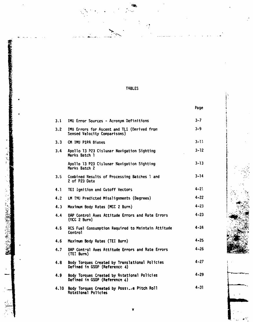
3.1 IMU Error Sources - Acronym Definitions 3-7)Y
3.2 IMU Errors for Ascent and TLI (Derivedfrom 3-g !Sensed Veloclty Comparlsons) |
3.3 CMIMU PIPA Biases 3-II !!
3,4 MarksAp°llOBatch13P231CislunarNavigationSighting 3-12 ).
Apollo 13 P23 Cislunar Navigation Sighting 3-13Marks Batch 2 -" -;_
3.5 Combined Results of Processing Batches 1 and 3-14 ...._'2 of P23 Data
4.1 TEl Ignitionand CutoffVectors 4-21 LC . _'w%/.," . ..
4,2 LM IMU PredictedMlsallgnments(Degrees) 4-22 , ;" .T_'.._,_,,_;
4.3 Maximum Body Rates (MCC 2 Burn) 4-23 ;:,!_?,
4.4 DAP ControlAxes AttitudeErrorsand Rate Errors 4-23 ....._",%i;)_i_
4,5 RCS Fuel ConsumptionRequiredto Maintain Attitude 4-24 L:-\:_._Control * _,:: .-F:
4.6 MaximumBody Rates (TEl Burn) 4-25 "::_'_i_'_':_
4,7 DAP Control Axes Attitude Errors and Rate Errors 4-26 _C(TEI Burn)
4.8 Body Torques Created by Translational Policies 4-27Deflned In GSOP (Reference4) i
4,9 Body Torques Created by R_tattonal Policies 4-29 .l_,_--,-_MDefined in GSOP(Reference4)
4.10 Body Torques Created by Poss_.,e Pitch Roll 4-31RotationalPolIcles
V
1973017939-006

?
$
r Tables (Continued) ,#
4
Page • it
-- 4.11 AGS Accelerometer Biases 4-32 i
4.12 AGS Gyro Errors (ASA 023) 4-32 _: t4.;. _.
I

Q
ILLUSTRATIONS
Page i
_.!•
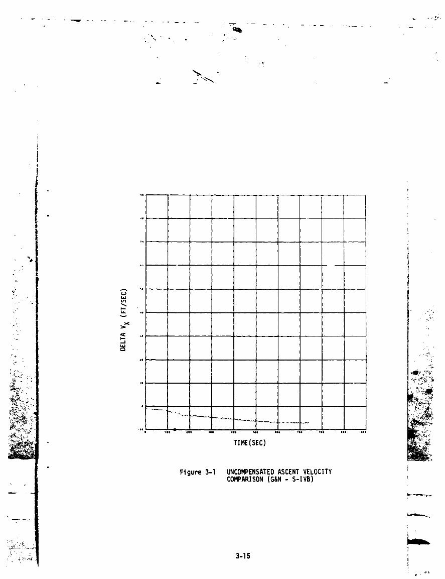
3-I UncompensatedAscentVelocityComparison 3-15
(GN-SIVB),DeltaVX )3-2 UncompensatedAscentVelocityComparisons 3-16
(GN-SIVB),DeltaVy
3-3 UncompensatedAscentVelocityComparisons 3-17
(GN-SIVB),DeltaVz
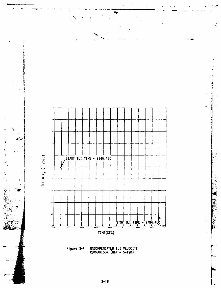
3-4 UncompensatedTLI VelocityComparison 3-18
(GN-SIVB),DeltaVX
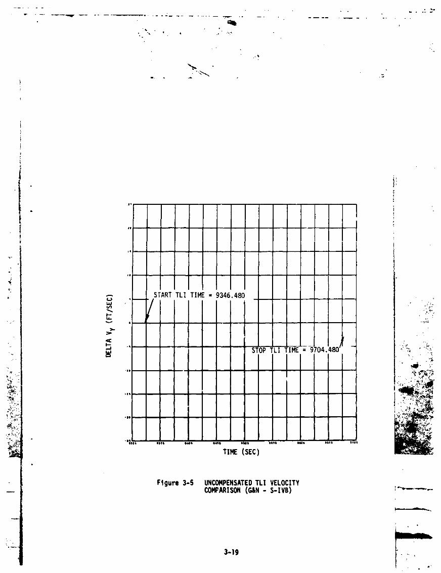
3-5 UncompensatedTLI VelocityComparison 3-19 i:.;_-'.
(GN-SIVB),DeltaVy ..
3-6 UncompensatedTLI VelocityComparison 3-20 . ..(GN-SlVB),DeltaVz ....._...'...:.._
: -: -_ -.'. _.__
3-7 CompensatedAscentVelocityComparison 3-21 .'_':-"-'`_;(GN-SIVB),DeltaVX :: •-:.:w_:_.
• _'._._,_3-8 CompensatedAscentVelocityComparison 3-22 ''-'_...:--':':_r/_
(GN'SIVB),DeltaVy :i_-."""-"_'__C_3-9 CompensatedAscentVelocltyComparison 3-23 :_
.'L.::._,,._"i:_f_,_'
(GN-SIVB),Delta Vz :"-._.:!_::.r;_L).-:_'-';_'
(GN-SIVB),DeltaVx _p,-_;-_-_;__ i"-_._3-11 CompensatedTLI Velocity Comparison 3-25 _ _
-_ (GN-SlVB),DeltaVy.._
_, 3-12 CompensatedTLI Velocity Comparison 3-26.:.- (GN-SIVB),DeltaVZ
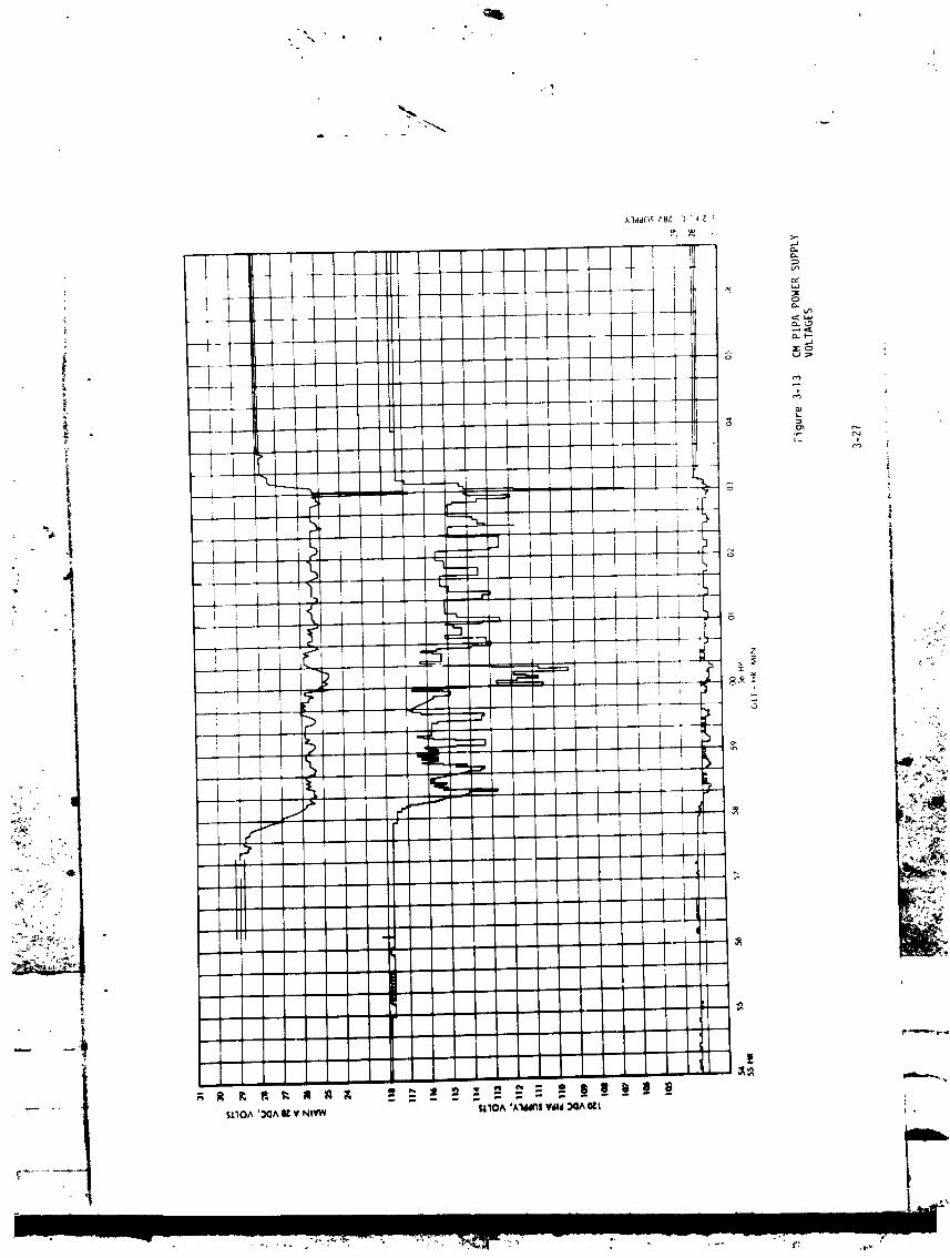
/,_ 3-13 CMPIPA PowerSupply Voltages 3-27 "_-"--"_
_ 3-14 PIPA OutputsandMSFNDoppler Data After 3-29 _ _ .....SMLOXTank Incident
r',
vii -...
] 9730] 7939-008

IIlustrations(Continue#)
Page
4-I MCC 2 Burn/P-AxisPhase Plane Plot 4-37
4-2 MCC 2 Burn/U-AxisPhase Plane Plot 4-39
_' 4-3 MCC 2 Burn/V-axisPhase Plane Plot 4-41
" 4-4 MCC 2 Burn/PitchGDA Position 4-43
_: 4-5 MCC 2 4 Burn/RollGDA Position 4-45
- 4-6 TEl Burn (Pre-BurnInitiationThroughThrottle-Up) 4-47' P-Axis Phase Plane Plot "_
_'_:*_" 4-7 TEl Burn (Pre-BurnInitiationThroughThrottle-Up) 4-49 ,,_-U-Axis Phase Plane Plot
) ,.
_'_o 4-8 TEl Burn (Pre-BurnInitiationThroughThrottle-Up) 4-51 ,..,....:._-'-__ V-Axis Phase Plane Plot _: ..*_
"_*.-_ 4-9 TEl Burn/PitchGDA PositionThroughThrottle-Up 4-53 _
_:_. 4-I0 TEl Burn/RollGDA PositionThroughThrottle-Up 4-55 ,..-__,°._,'_-_'-_lli_"_"
_}-,, 4-11 LM/CSM ConfigurationAuto Maneuverand Attitude 4-57 ,-'"_"_'_-__:_C__. Hold P-Axis Phase Plane Plot ......._..,",:,_-':._.
• c/¢- ,_,,,
"'_"_+?_ 4-12 LM/CSM ConfigurationAuto Maneuverand Attitude 4-59 ........._i_._._:,.iii.,, Hold U-Axis Phase Plane Plot
,_ 4-13 LMICSMConfiguration-AUto_laneuverand Attitude 4-61
_'_ Hold V-Axis Phase Plane-Plot
4-14 LMICSM ConfigurationAuto Maneuver P-Axis Phase 4-63 " *Plane Plot
_. i 4-15 LM/CSMConfigurationAuto ManeuverU-Axis Phase 4-65 _,-----,-_Plane Plot
4-16 LM/CSMConfigurationAuto ManeuverV-AxlsPhase 4-67 r--'_---.
_,iA Plane Plot itv_tt
9730] 7939-009

IIlustratlons(Continued)
• t
Page
4-17 LM/CSMConfigurationAttitudeHold 4-69P-AxisPhasePlanePlot
4-18 LM/CSMConfigurationAttitudeHold 4-71U-AxlsPhasePlanePLot
_L
4-19 LH/CSMConfigurationAttitudeHold 4-73V-AxlsPhasePlanePlot
4-20 LM/CMConfigurationManualManeuver 4-75andAttitudeHoldP-AxisPhasePlanePlot
4-21 LM/CMConfigurationManualManeuverand 4-77 . , ,_AttitudeHoldU-AxisPhasePlanePlot
, .-
4-22 LM/CMConfigurationManualManeuverand 4-7g ,Attitude Hold V-Axis PhasePlane Plot , ._...... ,,..
4-23 AGS/PGNCSSensedVelocityComparison 4-81 -', ," _._DuringTEXBurn ,__'_'
4-24 AGSSensedVelocity Along BodyAxes 4-82During MCC3 Burn (/': ''_
4-25 Roll _.ate and Attitude Error During 4-83 : , :-:,._MCC3 (AGSControlled) ". ;,"
4-26 Pitch Rate and Attitude Error During 4-84MCC3 (AGSControlled)
4-27 YawRate and Attitude Error During 4-85MCC3 (AGSControlled)
4-28 AGSSensedVelocity Along BodyAxes 4-86During MCC 4 Burn
4-29 Acquisition of YawAttitude for MCC4 4-87Burn
4-30 Acquisition of Pitch Attitude for MCC4 4-88Burn
tx _'
1973017939-010

• •
!
t
IIIustrations(Contlnued) ')
£ l
t
Page e" 0
4-31 Acquisitionof RollAttitudeforMCC 4 4-89 'Burn
4-32 SpacecraftAttitudeDuringMCC 4 Burn 4-90.,. _ : (AGSEulerAngles)
4-33 AccumulatedX-AxisSensedVelocity 4-91
-_ _ 4-34 AccumulatedY-AxisSensedVelocity a-92
- - 4-35 AccumulatedZ-AxisSensedVelocity 4-93
' I 4-36 X-AxisVelocityDifferences(NoAG$ 4-94"." Compensation)
4-37 Y-Axis Velocity Differences(_ AGS 4-95:,.. Compensation)
,= 4-38 Z-AxisVelocityDifferences(NoAG$ 4-96,._., , .,. I,ompensatlon)
_-:::! :ilV 4-39 X-AxisVelocityDifferences(Compensated 4-97....,:- forAGSAcceler_ter Errors):,_5_:,'._ ._-_::.---"- _-40 Y-AxisVelocityDifferences(Compensated 4-g8._,.:.'_---:,,..
_i}:_._:.._ for AGSAccelerometer Errors)
_,..,;-'-:-- 4-41 Z-Axis Velocity Differences(Compensated 4-99
._.:'-_:_-_.,_I forAGS AccelerometerErrors)•"_ _":-.:-._' '" 4-100'?_,-_,_:":.'.._I 4-42 AGS/PGNCSAngularDrift- "l"Body
4-43 AGS/PGNCSAngular Drift- "Y"Body 4-101 " ,
4-44 AGS/PGNCSAngular-Drift- "Z" Body 4-102
1973017939-011

NOMENCLATURE
I
ACA AttitudeControllerAssembly
" ACB (X, Y, Z) Accelerometerbias (channelsX, Y, Z)
ADSRA (X, Y, Z) Gyro drift due to accelerationalong thesp'.nreferenceaxis (ChannelsX, Y, Z)
ADIA (X, Y, Z) Gyro drift du_ to accelerationalong the_. input axis (ChannelsX, Y Z)"S #- J
.. AGS Abort GuidanceSystem
-_ AOT AIignmentOpticalTelescope,,I
_.. . APS Ascent PropulsionSystem |. ASA Abort Sensor Assembly
1
• BDA Bermuda (trackingstation) " '
•.. CDU CouplingData Unit -
COAS Crew OpticalAlignmentSight
CM CommandModule, • '.,
-_.. CMC CommandModule Cemputer i
DAP DigitalAuto Pilot p..-_-
-.._"- DEDA Data Entry and Display Assembly !'% _
'_;:- DPS Descent Propulsion System .;:_'_W._-_,_- . ..-<,
_,__-.:, ;'_ DSKY Display and Keyboard __:':"
-o'_,::-'-. EPC Earth PrelaunchCallbratlon
_".:_'_':::'. FDAI FIIght DirectorAttlrude Indicator :-"
_"_"_:" GDA Glmbal DriveActuator _"_'";_,T-_ _-_.,,,_._._;.,_-_ GDS Goldstone (tracking station) _
GET Ground Elapsed Fime (Range Time) _"1
• G&N Guidance and Navigation
GSOP Guidance System Operational Plan
HOPE Houston Operations Predictor/Estimator .--..
IFC Znfltght Calibration
IMU Inerttal Measurement Unit _'--._
IRIG Inerttal Rate Integrating Gyro
JPL _et Propulsion Laboratory
1973017939-012

t
L
Nomenclature(Continued)q
I
iLGC LM GuidanceComputer
I LM Lunar Module
LOS Line-of-sight
LOX LiquidOxygen
•: MCC MidcourseCorrection" _ I MERU Milli-EarthRotationalUnits
i
_ #-., MIC Minimum ImpulseControl (mode) !-" , T_SC Manned SpacecraftCenter !
_. NASA NationalAeronauticsand Space Administration I
r_AT NASA Apollo Trajectory iG
Omega P'error Rate error about P axis i "Omega U'error Rate error about U' axis
I; Omega V'error Rate error about V' axis
.. P error Yaw axis error
PGNCS PrimaryGuidance,Navigationand Control _jrSystem '""
_.,"' iP PIC Pre-:nstallationCalibration
ZL_. PIPA Pulsed, IntegratingPendulousAcceleromet_r_ ,_--..,:..!
- PPM Parts per Million ,%;_',
- PTC Passive Thermal Control '_'_
h
_..,.. II RCS ReactionControlSystem _,.-REFSMMAT Reference to StableMember Matrix - _.'"._
_:_'__" RHC RotationalHand Controller
_" _":- RSS Root of the Sum of .__Squ._.esRTCC Real Time Cor,trol tenter
SIC Spacecraft
SFE(X, Y, Z) Scale Factor (Channels X, Y, Z) "---"
SM Service Module
SODB System Operational Data Book
SPS Service Propulsion System
SIVBIU Saturn IVS Instrumentation Untt
xti
1973017939-013

Nomenclature (Conti nued)!
TEI Trans-Earth Insertion• THC Transl ati onal Hand Co.ltrol let
TL! Trans-Lunar Injecti on
TTCA Thrust and Translation Controller
U error ComputedErrors
-_ - U' error ComputedErrors
V error ComputedErrors
.. V' error ComputedErrors
__/:" . VG Velocity Gained -" VO (X, Y, Z) Velocity Offset (X, Y, Z)
ax 14easuredgravityvector in IRU coor-,-. dinates (x) -.
ay 14easuredgravityvectorin IHUc_)r-: dinates(y)
- az Heasuredgravity vector in I14Ucoor- I:dtnates (z)
(
ug 14tcro-gravi ti es t_._"_;P, U, V axis DAPcontrolaxisorientedrelativeto _
LM body axes as shownbelow: _-'---_;__._._ , - _i_._.,_I__'._-_z -,
,p
._,.,._.'
-:_:_9 12 13 16
-':
II 15
;4
i ,R
/ /'_ / .,,_ I / Fo_w,,o6// / -v \_/ o,,ec'r_ )
? 3 FOqAN/ _ OCCUP*Nr
! QUADIII QUADIV OF THE LM
| ¢ Q 4 l(,Y)
xlll
1973017939-014

1.0 INTRODUCTION
o
This report preses%tsthe conclusionsof the analysesof the i,lflight ,
" I:_..-_l_rlce of the Apollo 13 _ian (_li.d_, Navigati.cm and O:m_l '
equiEm_mtamboard the C_4-I09 and IM-7 spaeecrafts. This analysisis
supplement1 to the Apollo 13 Mission Beport (Beferenoei).
!
!-
-\ - •2."':
,q
;
]9730]7939-0]5
} 2.0 SUMMARY
t
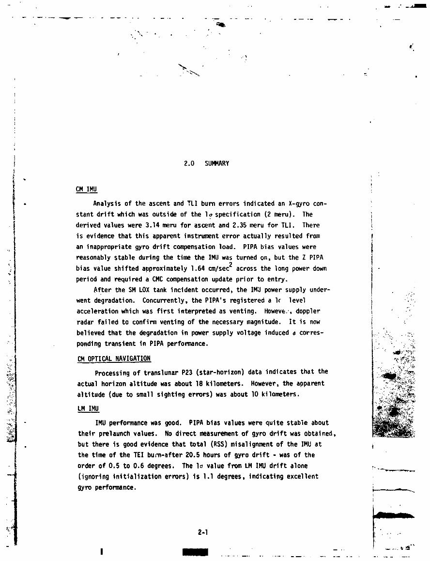
I CM IMU
I . Analysisof the ascent and TLI burn errors indicatedan X-gyro con- '
I stant drift which outsideof the Io (2 meru). Thewas specification
I
f• derivedvalueswere 3.14 meru for ascent and 2.35 meru for TLI. There
is evidencethat this apparentinstrumenterror actuallyresultedfrom
an inappropriategyro drift compensationload. PIPA bias valueswere 1L
reasonablystable during the time the IMU was turned on, but the Z PIPA
bias value shiftedapproximately1.64 cm/sec2 across the long power down i!
)period and requireda CMC compensationupdate prior to entry.
After the SM LOX tank incidentoccurred,the IMU power supply under- )
, went degradation. Concurrently,the PIPA's registereda I{ -level i ;__
accelerationwhich was first interpretedas venting. Howeve.',doppler (( _ ._":) ""
radar failedto confirmventing of the necessarymagnitude. It is now (;
believedthat the degradationin power supply voltageinducedd corres- _.:-°C-_- _;
pondlngtransientin PIPA performance i:_" _" i ":::_:t• : ._._-
" CM OPTICAL NAVIGATION I, ,_-._J'__._..,.,
i_. Processing of translunar P23 (star-horizon) data indicates that the 1 ..
-_ actual horizonaltitudewas about 18 kilometers. However,the apparent ., ..,..;.:_j?_:.,..: c_.c:-;0':_"-_-
altitude(due to small sightingerrors)was about I0 kilometers. .-,.._.L,.,_%_j_._,
.'i IMU performancewas good. PIPA bias valueswere quite stable about ' ;<_'-
-_ their prelaunch values. No direct measurementof gyro drift was obtained,
. but there is good evidencethat total (RSS)misalignmentof the IMU at
the time of the TEI bu:_-after20.5 hours of gyro drift - was of the
- order of O.S to 0.6 degrees. The lo value from LM IMU drift alone _,-_-._.--_---,-,(ignoringInltlallzatlonerrors) is 1.1 degrees, indicatingexcellent
gyro performance..... -_
2-I ......
i __ ,,
1973017939-016

LM DIGITALAUTOPILOTF
Duringthe mission the LM DAP was called upon to controlboth LM/CSM ° ;
and LM/CM spacecraftconfigurationsin auto mneuver and attitudehold modes.L
- Performancewas satisfactoryin all cases althoughin some instances _ _
violationsof deadbandlimits did occur.
! The roll GDA was observed to drive approximately-I.3 degreesfrom -s
its initialpositionat the start of the TEl burn, stimulatingconjecture
" __i that the engine gimbal trim functionmight have been abnormal. Detailed ), J_ analysisindicatedthat this positionchangewas necessaryto relievecom-
= i plianceand correct for initialmistrim. Performanceis now believed to.'j _,
"_ " _ have been nominal.\
• Difficultywas encounteredwhen attemptingto maneuverthe space-
. , craft into the PTC attire,4_.followingthe TEl burn. Downlinkdata were .
.: not availablefor the maneuver,so that investigationwas necessarily
i
restricted. One explanationwas foundby a theoreticalexaminationof cross _
•-- couplingsresultingfrom variouscontrolmodes. It was determinedthat
_ the use of rotationalcommandswould have resultedin significantcross
_"_', coupling (due to jet impingementforces) and drastic alterationsin the ...._',"
_,_'_:,-,._,,,"_ intendedcommands. Althoughpurelytranslationalcommandswere planned for _"_. i,,',z- this maneuver it is hypothesizedthat some rotationalcommandswere inter- -:'_-,C_':"
,o_.......,,_- mingled and were the source of the problem. _EI_Y,
a;_'._"_!_i Another possibleexplanationis that the difficultyarose from the "."_;,
:{:-_'_;_',, necessityof determininghand controllercommandspurely by interpreting ' ',---_-/_
•_"-_ gimbal angle displays on the DSKY. This was necessary because the FDAI was _
powered down. , _5_,
LM ABORT GUIDANCESYSTEM
The AGS was used for spacecraftcontrolin two burns. MCC 3 and ....
MCC 4. In both cases, performancewas satisfactory.
2-2
]9730]7939-0]7

d
w - ,q _ ..........
i
: AGS gyro and accelerometererrors were estimatedfrom free flight
t _ data and from AGS/PGNCSvelocitycomparisonsobtainedduring the TEl ,
i burn. Instrumentstatic errors showed excellentstability. The TEl_- burn affordedthe only opportunityfor observingaccelerationsensitive
I " errors. Instrumentdynamicperformanceduring that burn was within the i2_ limitsdeterminedfrom the ASA023 error model. This is excellentper-t
formance,particularlyin view of the fact thaL the ASA023 dropped
23 degreesF below its specifiedminimum temperature(60 F) during the
_ . _. 24 hour period in which it was shut down prior to the TEl burn. i
; #_.j LM OPTICAL ALIGNMENTCHECKS
_. :• ., Prior to the TEI burn the LGC was used to aim the AOT line-of-sight
_"" in the LGC calculatedsun direction. This was done to assess IMU align-
ment errors and resultedin an estimatedmisalignmentof 0.5 degrees. ?-":::.
_ " By its nature,the check could not resolveerrors about the line-of-sight. :
However,the line-of-sightdirectionwas such that misalign_entsabout
it had negligibleimpacton significantstate vector errors inducedby I
._. _- the IMU during the TEl burn. As conducted,the check determinedonly i..ci
_;i" .-"_ the ,nagnitudeof the misalignmentin one plane - that plane in which _i_,-i_"':I_ ,salignmentswere of greatestconsequence The directionof these _"[__
_,:. , errorswas not determined,and thereforethe appropriatecorrectiveIMU_:L':_,.,,.... torquescould not be calculated. The IMU misalignmentgenerateda burn;_,:._,_.,_,_._.;-',-::_ error of approximately5,3 feet/secondin the TEl burn Unfortunately,much
of this errorwas in the directionmost criticalto entry flight path angle; _i._,_.¥__;'_'-.._'_ the resultant(potential)error in the _st-TEI trajectoryentry flight L'_,
_,_:_._._-_-:_I path angle was in excess of -4 degrees. The allowableerror in flight path
. angle is 0.5 degrees. Two midcoursecorrectionswere subsequentlyrequired .to correct this error.
I
t
!;__ ..... --'_' 2-3
• _:c_"_'_:_'_ L
1973017939-018
e
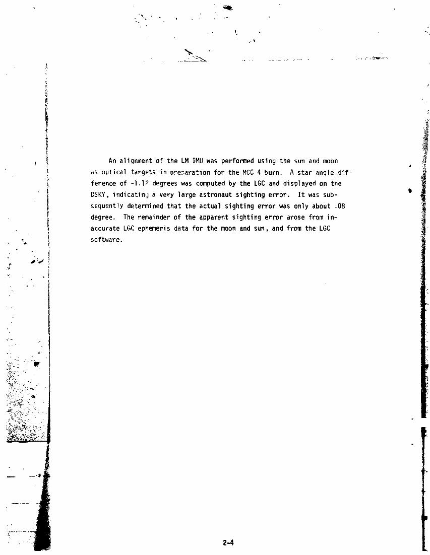
t _ An alignmentof the LM IMU was performedusing the sun and moon _-
_ as optical targetsin preparationfor the MCC 4 burn. A star an_le d_f- i
i ferenceof -l.I? degreeswas computedby the LGC and displayedon the
DSKY, indicatin_ja very large astronautsightingerror. It was sub-
scquent!ydeterminedthat the actual sightingerror was only about .08
degree. The remainderof the apparentsightingerror arose from in-
i accurateLGC ephemerisdata for the moon and sun, and from the LGC
. i software.K
. .

• . +
+
I
3.0 CM SYSTEMS
i 3.1 CM INERTIALMEASUREMENTUNIT
3.1.1 VelocityComparisonsDurin9 Ascent and TLI
The Apollo 13 CM IMU performanceanalysiswas based on comparisons
of Apollo (denotedG&N) and Saturn (denotedS-IVB)measured velocities.
Analysiscenteredaround the "sensed"velocities- those resulting
_'_, from integrationof that portionof the vehiclesaccelerationwhich can
i be sensed by the accelerometers. Sensed velocitiesexcludethe influence
s-d of the gravitationalfield. In additionto the sensed velocitycom-
_:, : parison,a cross check of ascent phase resultswas obtainedby analyzing++ .... total"velocitydifferences. Total velocity is the actual vehicle _,
velocity in inertialspace. It is obtainedby integratingboth sensed •+
_* acceleratien(due to engine thrusting)and gravitationalacceleration.
The cross check was performedbecausetelemetrydata dropoutscaused i *,
_+ minor discrepanciesin the GN sensed velocityestimates. Sensedand _ ._"_i_' _• total velocitydifferencesare presentedbelow for the end of the ascent I+_"
+,' _ phase (t = 752 seconds CMC clock time) and for TLI cutoff (t = 9704.48) 7_
+-+_......-, Type of AX A{ ,',Z
,_? L+ Time Comparison Comparison (ft/sec) Ift/sec) (ft/sec) _"+_;
+_o_.... 752.0 sec Sensed G&N - S-IVBIU -6.75 87.04 - 3 82
+,_ " Total G&N - S-IVBIU -5.41 75 51 1.02_I_:jF_,+}•**: 752.0 sec'__+_"_'-+ - 9704.48sec Sensed G&N - SIVBIU -20.50 - 2.50 2.03 i,_
- IU representsthe edited Saturn telemetrydata•
i
1973017939-020

i
d
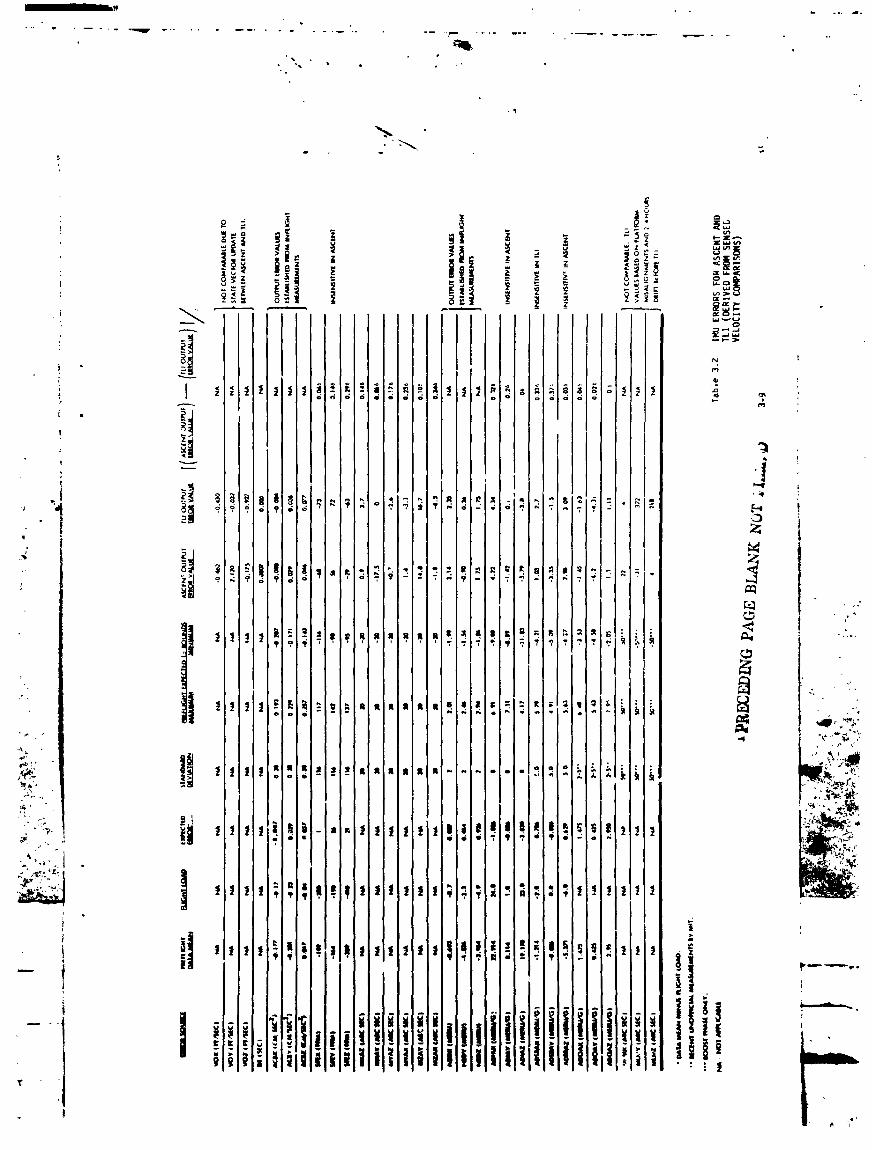
The ascent and TLI uncompensatedsensed velocitydifferences(G&N -
S-IVBIU)appear in Figures3-I through 3-6. Those IMU errors solved for " iin this analysis are defined in Table 3.1. IMUerror sets derived to
fit the ascent and TLI velocitydifferencesare presentedin Table 3.2. •
Close agreement was obtained between the results of the sensed and total
velocityanalyses,so that inclusionof the results for the total was
unnecessary. Compensated sensed velocity differences (G&N- S-IVBIU, where
the G&N data has been compensatedwith the derived IMU errors)are pre-
sented in Figures3-7 through3-12. _L
3.1.2 Ascent and TLI Error Determination
The Apollo 13 G&Csystem accuracy analysis was based upon the deter-
mination of a common set of errors which resultedin small residualsfor ." . -_
both the boost to orbit phase and the translunar insertion phase. The
analysisis accomplishedwith the aid of a Kalman Filterwhich solves
for a "best" set of IMU errors for minimizing the velocity differences
in a least squaressense• Several constraintswere imposedon the ,_
errors used. The bias values for accelerometers(Table3.3) and gyros : . ._; were forceJto be in close agreementwith inflightdeterminedvalues _ wlp_,_"_:
and the other error terms were chosento agree favorablywith preflight _ ._:_calibrationhistories. Due to various physicalfactorssuch as actual -,"_c_'_;_
parametershifts during the boost phase and degradationof the reference ' _"_a?._:data between the two flightphases (2 4 hours of drift between ascent _'_,_:_,_
and TLI) it was again recognizedthat all of the above conditionscould __not be met at all times, Based on englneering judgement, the approach
pursuedwas to seek two sets of error sourceswith bounded variations __'_
(LIc). The error terms derivedfor the sensed analysesare presented "
in Table 3,2, and using these values,the G&N correctedtrajectories
fit the respectiveexternalmeasurement(S-IVBIU)trajectories. The maxi- --.
mum deviationbetweenthe derivedascent and TLI error sourceswas 0.86_.
, . . ...... _w
j3-2 '_ _
1973017939-021

, The derived boost and TLI values for NBDX (X Gyro ConstantDrift
Rate) exceededthe l_ (2 meru) instrumentstabilitycriteria. The de-
rived values were 3.14 meru (ascent)and 2.35 meru (TLI). These
! . represent_.57_ and 1.18o values respectivelyfor boost and TLI. Pre-
_ flight data obtainedat Cape Kennedy,from 3 July 1969 to 3 April 1970•
revealeda pronouncednegativetrend which peakedout at -3.3 meru on
6 January1970. Overall NBDX Cape test results are somewhaterratic.
Followingthe referencednegativepeak, NBDX resultsvaried considerably.
For the subsequent6our calibrations,the quantitybegan trendingpositive
and the last calibrationvalue on 3 April 1970 was 0.5 meru. The CM com- |'( •
- puter erasablememory compensationvalue for NBDX was -0.7 meru. If the
term continuedto trend positively,it is probablethat an effectiveerror
on the order of 2-3 meru did exist during ascentand TLI. Consequently,
. it is understandablethat the derivedvalues for NBDX did exceed the l_
instrumentstabilitycriteria. The apparentlylarge shift in drift prob- __'
. ably reflectsa compensationerror rather than instrumentdegradation.
All other error sourceswere within lo limits.
3.1.3 Quick Look Evaluation :--"C
It is worthwhileto point out that a techniquehas been developed _4s_i"
'.s _._ for takinga gross "quick look" at IMU performancewithout recovering j.._ _;
'_%;_. individualinstrumenterrors. This was done for the Apollo 13 CM IMU ").C.)_...._- by comparingactual ascent cut-off state errors with standarddeviations ,._,:y.
,,_:.-, of these errors. The standarddeviationsused for this comparisonwere )_X_C__
,._._ obtainedby integratingan ensembleof Io IMU instrumenterrors along F :•'.,_
_ -: the ascent trajectory. ResultantIo state errors formed trajectory
bounds from which IMU performancecould be gauged in the system sense;
i.e., from which it could be determinedwhether or not overall IMU per-
formanceas a navigationinstrumentwas within Io bounds. This gross
"quick look" techniqueprovidedan additionalconfidencefactor in theI_
derived NBDXerror source values discussed, inasmuch as it demonstrated _-.-.-_
that IMU performance was not within specifications during ascent. A
comparison of actual with lo velocity errors Is presented as follows _"---_
-'-- (at t - 752 seconds GET):
• 3-3
.... . _.__u_*_
1973017939-022

_l
i
X Y Z _X AY AZFLF_tI* (Ft) (Ft) (Ft/Sec) (Ft/Sec) (Ft/Sec) •
I,;: 1434 27630 3542 4.46 61.89 9.88
i, Actual: 3555.8 32220.6 1316 -5.41 75.51 1.02 o
I *The positionand velocityvalues are totals-, (u,itsas noted).
"_ el, ,
3.1.4 Impactof Power Supply Degradationon CM PIPA Behavior
-_ Immediatelyfollowingthe SM LOX tank incidentat 55:54:53GET,
"' " the CM downlinkrecordedPIPA pulses which resembledthe effectof venting.
However,effortsto reconcilethese data with dopplerradar measurements
met with failure. Consequentlyit was theorizedthat the actual pheno-
menon being observedmight be a bias shift in the PIPA'sdue to power
, supply transients,rather than accelerationsdue to venting. To support
this hypothesis,an effortwas made to correlatepower supplytransients
" :• with observedPIPA data.
,L:/:.;_ Figure 3-13 is a plot of the 28VDC Main A, 120VDC PIPA supply and
_.;:i" the 3.2 KC 28V power suppliesat the time of the LO2 tank event at 55:54:53
__ ;" • GET. The 120V PIPA supply and the 3.2 KC 28V supplybegan to degradewhen
_._¼,_'L].,_e the 28VDC Main A supply reached26.3 volts. Figure 3.14 is a plot of the
•T_-;-_.:L accumulatedthrustvelocity (Vsx,Vsy, VSZ) indicatedby the PIPA's through_.,, _'i_;'_'.;_,,,_; .,.> the time of the voltage transient;superimposedon this is a plot of MSFN
,_,_:,._,-:_ do,pier radar residualsfor the same time period. The change in PIPA -
__ velocitiescan be directly correlatedto the degradedvoltage. The reason
for the differentPIPA responses(i.e.,XPIPA does not show response to the
sharp voltagetransientat 56:00 and 56:03 as do Y and Z) is unknown.
.... _'--- _:r Referringto the plot of the Bermuda/Goldstonetrackingstationdoppler: _ residualsthroughthe period of interest,no appreciablechange is noted
between 55:57:56and 56:03:10,the region of the I20V PIPA supply transient.
• ,u _ ..... . .
1973017939-023
Shifts in the doppler residualsnear 55:55:00and 56:03:30resemblevelo-
city changesindicatedby the X PIPA which is pointed principallyalong iI " the LOS to Earth. The trend shown by the X PIPA however,is not reflected
i in the dopplerdata, thus indicatingthat X PIPAvelocity indicationLwere
q
erroneous.
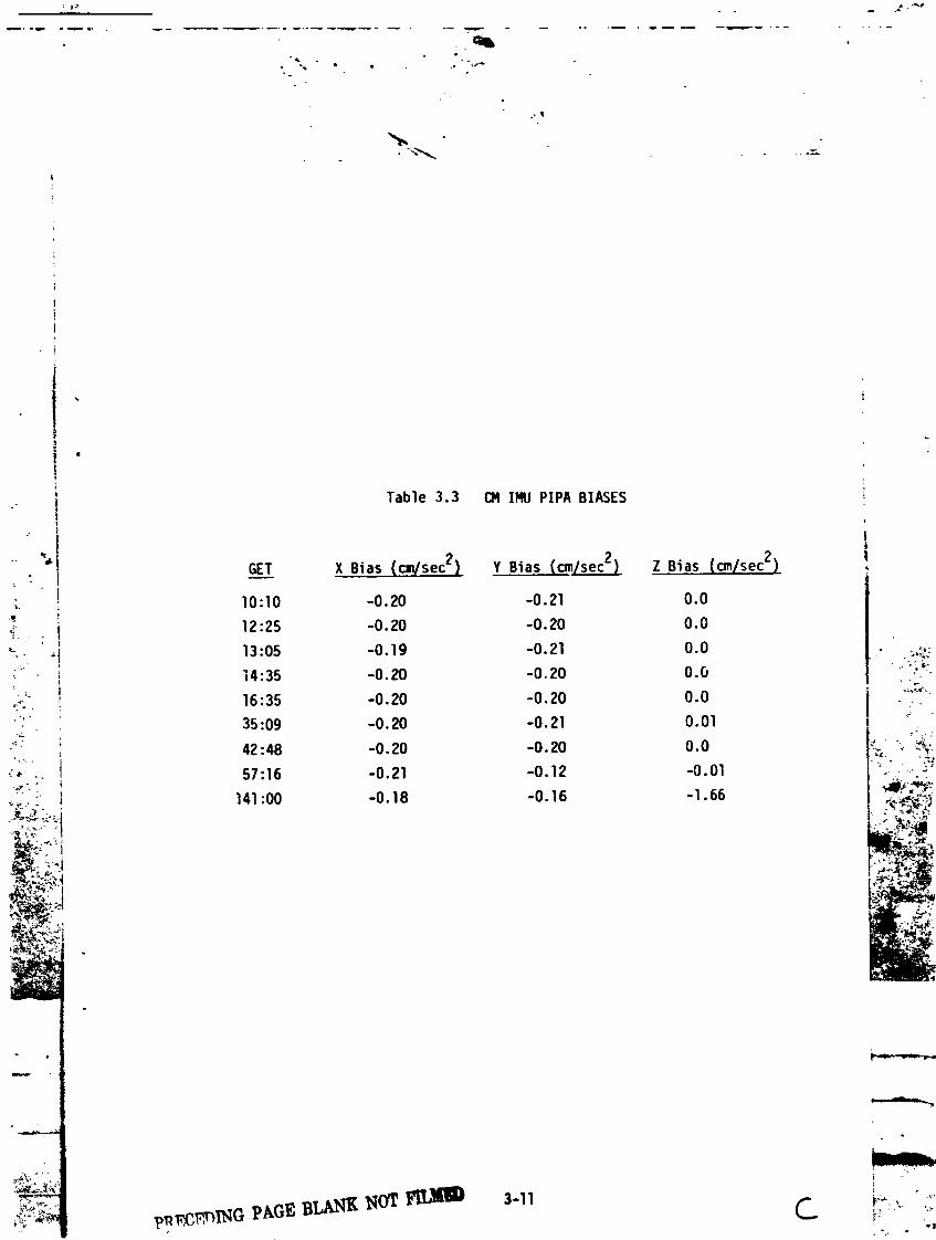
Followingthe event, the CSM IMU was powereddown (includinginstrument
heaters)at 58:40 GET and remaineddown until 140:lOGET. At IMU power up,
a shift of 1.64 cm/sec2 was noted on the Z PIPA and as a result a bias update
was performedprior to entry, fable 3.3 is a summaryof the PIPA biasA
j beforeand after the event.
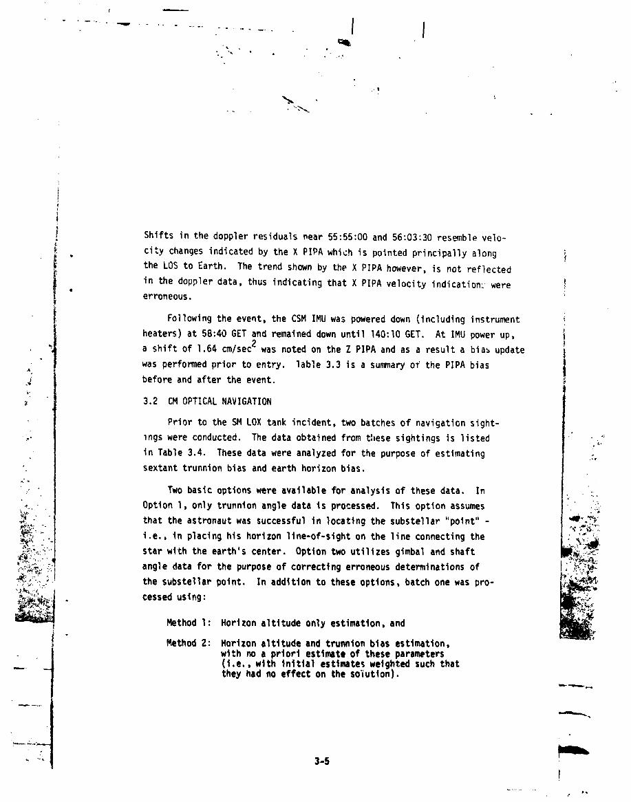
3.2 CM OPTICAL NAVIGATION
Prior to the SM LOX tank incident,two batches of navigationsight-
_,. ings were conducted. The data obtainedfrom these sightingsis listed ' . "_
in Table 3.4. These data were analyzedfor the purpose of estimating •_' sextanttrunnionbias and earth horizonbias.
i, _ Two basic optionswere availablefor analysisof these data. In _. _,
• Option I, only trunnionangle data is processed. This option assumes _:
_. - that the astronautwas successfulin locatingthe substellar"point"- -I_-,_"
_:'_:;__...'"'I i.e., in placing his horizon line-of-sighton the line connectingthe ,,_:_C;;_I_.,_ _: j star with the earth'scenter. Option two utilizesgimbal and shaft F'_:._._
__'_:_ angle data for the purposeof correctingerroneousdeterminationsof ,._.:_,
_:_'--_ the substellar point. In addition to these options batch one was pro- _'?'_C_'_-_'_ cessed using: _
Method 1: Horizon altttude only estimation, andi
Method 2: Horizon altitude and tTunnion bias estimation,with no a priori estimate of these parameters(i.e., with initial estimates weighted such that
"-_ -- the_ had no effect on the solution).
] 9730] 7939-024

.... m
"_ • • e
The combinationof methods one and two with options one and two
yielded four cases. The output of these cases were used as the input
(initializationvalues) for the processingof batch two. Table 3.5| presentsthese combinedresults. Option l resultsfrom batch l were o
used onl) with option l runs fer batch 2. Likewise,option 2 results i
from batch 1 were used only with option 2 runs for batch 2.
The results indicatethat the actual horizon altitudewas about 18
kilometers. However,due to small sightingerrors the astronautwas
actuallysightingon an effectivealtitudeof about lO kilometers.
3-6
_,1 j''
1973017939-025

_-, ",-¢ 0 ",-¢ 0 _ 0 .,-4 : l=
• Q) _ Q_ (U a)
0 0 0 0 • _
| _ r,j .,-¢ _ U .,.4 ",'4 U "i,,4 ",-¢ U •
m
3-7
4.
1973017939-026
1973017939-027
! •
i Table 3.3 CMIMUPIPABIASES :
" "_i GET X Bias(cm/sec2) Y Bias{cm/sec2) Z .Bias(cm/sec2)
• l 10:10 -0.20 -0.21 0.0
_:_- t 12:25 -0.20 -0.20 0.0!
,_. ,j 13:05 -0.19 -0.21 0.0 . _.,,:_\_
14:35 -0.20 -0.20 0.0 :"_':_',.
.,f, 16:35 -0.20 -0.20 0.0 _ .,._ 35:09 -0.20 -0.21 0.01 _
"_ 42:48 -0.20 -0.20 0.0 _i '" _';"•-"_ 57:16 -0.21 -0.12 -0.01 ' ....,_, J
_,,.<:" 141:00 -0.18 -0.16 -I.66 _ _
"NN
,:_i._ t,_c_,P-,BI.,A.t',IK1',IO'£_ 3-11
1973017939-028


3-13
1973017939-030

.Immm......m... JmL. _,.L
i .................
L
{ i
Table 3.5 COMBINEDRESULTSOF PROCESSING !BATCHESl AND 2 OF P23 DATA
1Initialization Option 1 Results Option 2 Results ,
Run l
Met_od 2 10.61 km lO.13b 0.00952 l_]rad -0.02236 J
ah 4.88 km 4,57 ]"- _b 0.07975 mrad 0.05386
• - p O.27406 O.12275 I!
Run 2#_,,x Met_od 2 17.42 17.55H
" " b -0.02827 -0.03093
- . oh 4.8B 4.57ob O.07975 O.05386p O.27406 0.12276
Run 3
Me_od" I 9.61 9.86b -0.05236 -0.05236
> :" oh 4.69 4.53
:;, ... _ ob I0 "5 i0 "5..... -', : 0.0 -O.O00nl
_.. • Run 4_"_ _" Met,hod 1
"-_ """:"" "' II 17.04 17 35
,,_°":-"-._._.Q b -0.05236 -0.05236_,?_',__o oh 4.69 4.53
:_ ,_ :** p 0.0 -0.00_I
where,
h = estimate of altitudebias
b = estimate of trunnionangle bias
oh = standard deviation of estimate of altitude biasfrom covariance matrix
ob = standard deviation of estimate of trunnion biasfro_.covarlancematrix
p = correlationcoefficientof estimatesof altitudeandtrunnionbias from covarlancematrix
3-14
1973017939-031
--,,. ......., . .... . ....... _.
i
+'it
_o
'en +
. It
_ 4o ,
-,1
_ TIIVlE(SEC)
Figure 3-1 UNCOHPENSATEDASCENTVELOCITYCOHPARISON(G&N- S-IVB)
';"" _ 3-15T
]9730]7939-032

• s
i
Ftgure 3-2 UNCOHPENSATEDASCENTVELOCITYCORPARISON(G&N- S,-IVB) """'
3-16
1973017939-033

ee - 4
ee ;
1"! 0.,
: -2"Jk
t:-,
•, ,,,_. ,_:,,_ TIME(SEC)
• i, Ftgure 3-3 UNCOMPENSATEDASCENTVELOCITY '
--.- _-_r-._ COMPARISON(G&N - S-IVB)
7
1973017939-034
o
G
,., STARTTLITIME= 9346.480
m
,_' _
ee
J I IIIIIIII_j , STOPTLI TIME-j9704.48()'
TIMEISEC)
Figure 3-4 UNCOMPENSATEDTLI VELOCITY 1COMPARISON(GLEN- S-IVB)
lib
3-18
1973017939-035
i
--, STARTTLI TIME= 9346.480
" / "
l,R STOPTLI TIME= 9704.480 "'_'_"
"'-_ . h.f•¢'
*| IIII I_I till IUl fill il till IIII __TIME (SEC)
Figure 3-G UNCOMPENSATEDTLI VELOCITYCOMPARISON(G&N- S-IVB) '"--'"-'---'
3-19 i ....' ..
1973017939-036

IIi
-i
i
• j
i
1 iitt,t
• 3-20 ! ,_
1973017939-037

.......... _ .......... w w,. . w , u m , . _
4
J
I ,t '• i
4
t
t •u,I
TZNE(SEC)
' ! Flgure 3-7 COHPENSATEDASCENTVELOCITY ,.----.-,._-- COHPA.'tlSON(G&N- S-IVB)
.. 3-21 I
1973017939-038

"" " ' _ ' "umllr ........ .... h _w w . ..,.
.,q
.... 3-22 t
1973017939-039

+.
%
J
i!
!
.-0 ._
- -I
"'"* + :"+++'IZ+t++
+_"+, + ,. _+++_,,+.,.
_+++. • :+c:_+.+-+.) ,.... ,- . •+;++.+,+.._+'_- + +++ _++,,
,:+,+_.++++ k++, -++++.
r:+ ' " _, "'++"+
•,+_++,+, TIMElSEC)
Figure 3-9 COHPENSATEDASCENTVELOCITYcomMiso_(Gea- s-lye)
i3-23 t
*k,
1973017939-040

v i . .,. .,,mill. .............. . . - ,."'" " " '" "--' ........
Vq
t|
t
!, I _ i!.i
" "¢ STARTTL! T[HE= 9346.480jr 1 . _.
LLa _ _"V')
.
x ISTO_TL: TIHE ,, 97 4.4
I--" =, "'
%t w ,
?:\.,. e, :q''f"'
emlMll
TZHEISEC)
1973017939-041

i IiI
; l
_;..... STARTTLI TIME= 9346.480
.t:-
- < STOPTL] TIME- 9704.4E,,.j -'
_,'-:_:-_,-_,;:..! TIME(SEC) '
--. . .,..,_t---.,. Figure 3-11 COMPENSATEDTLI VELOCITYCOMPARISON(G&N- S-IVB)
3-25
]9730]7939-042

Z
8_ _-
0

,!
1973017939-045

4.0 LM SYSTEMS
4.1 LM INERTIALMEASUREMENTUNIT
4.1.I Trar.searthInjectionBurn: Cut-OffVelocity Errors
4.1.1.1 Velocit_fErrors
Velocityerrors generatedby the IMU during the TEl burn were in-
_ vestigated. To do this, "best" ignitionand cut-offvectors were deter-
mined from free flight data• Three such vectorswere determinedfor the
_; time of ignition;one was determinedfor the time of cut-off. These
_ vectorsare presentedin Table 4.!. The ignitionvectorswere extra-
polatedto the time of cut-off using accelerometerdata from the LGC _,
downlink. These extrapolatedvectorsmay be thoughtof as LGC "best :_
guesses"as to the vehicle state at time of cut-off. They were differ-
enced with the free flight cut-offvector (assumedcorrect)to obtain
estimatesof the IMU inducedtrajectoryerrors• Only the velocity i;_
'_ .-, componentswere calculated,and the resultsof these calculationsare _:,_.
i_;_/,, presentedbelow for each ignitionvector and each of three coordinate ',_,)_C_:
._._ , frames• The coordinateframes chosenwere: BRCS (BasicReference _li_,'"_k'u;":?_
_ Coordinates);IMU and; local All referenceframeswere moon centered. _,_,_The local frame is defined to agree with MIT's convention,as follows: I.",._,,,_"
X: completesthe right hand set , _,;-_,
Y: along the negativeangularmomentumvector (-R_x V_) _ ",/_
Z: along the negativeof the radius vector (-_R)
AV _V AV("Best"- NBEX343) (GYMX289- NBEX343) (HAWX300- NBEX343)
, X Y Z X Y Z X Y Z
BRCS (+3.85;+3.02; +2._2)(+2.92;-I.21; +9.62) (+3•53;-0.14; +_.44)
IMU (-3.77;-3.83;-1.07)(-2.72;-2.92;-g.31) (-3.23;-3.53;-7.80) '_'--""-_',
.... LOCAL (+5.46; +0.41; -0.56)(+5.10; +8.72; -0.72) (+5.70; +7.12; -0.66)
Magnirude 5.48ft/sec 10.13 ft/sec 9.15 ft/sec _-.r---.,q
4-1
-- m,, ,m_ _
] 9730] 7939-046

%
Th_ GYMX 289 and HAWX 300 ignitionvectorsyield similarvelocity
errorswhereas errors for the "best" ignitionvector differ from these
m_rkedly. The first two vectorswere obtainedby the RTCC in real time.
GYMX 289 was the vectorwith which the TEl burn was targeted. However, ,:
i both vectors containonly data obtainedprior to perilune. The "best"
I vectorwas obtainedat TRW by fitting data on both sides of perilune.r
i It providedmuch more satisfactoryrange and doppler residualsafteri periluneand consequentlyhas been chosen as the preferredvector for
. _ purposesof this report. The disagreementbetweenthe preferredvector,i
_ _,; a.ldthe other two vectors lie almost entirelyin the out of plane
_ ("Y", in local coordinates)direction;this is the direction in which"L i
. . i velocityis least accuratelydeterminedby ground based radar (and,
i therefore,the one in which the greatestuncertaintiesare experienced) • "'-"
!, " ._,
i 4.1.I.2 Error Sources ....l
The principalsourcesof velocityerror are likely to have been
I IMU misalignments(_.7 deqrees/axis due to l_ drifts alone) and dis-
crepanciesin the ignitionand cut-offvectors obtainedfrom free flight 2_
_. data. These free flightvector uncertaintiesare not known explicitly. _\_;
-_._ i However,the ignitionvector is creditedwith very good accuracy;on Lhe _/_
-'!_,,,_,, _i orderof .lft/sec,out-of-plane,and lessthan.lin theothertwo |: _
,_," _ axes. The cut-offvector is suspectedof greatererrors, but these may ....,
"i_-/_,i__ well be less than one ft/sec (total). With that hypothesis,it was _"_-'_"_-_
_;,,,., concludedthatthemajorityof the errorcouldbe attributedto IMU _,C.,_, misalignments.Sincealignmenterrorsareperpendicularto thevelo-
_,__ citygained,itwas of interestto determinehowmuchof the observederror satisfiedthat condition. This was done as follows:
Vp (parallelto VG)= (V) • (unitVG) - -I.47 ft/sec
-_ Vp = Vp (unitVG) = [-I.27;+0.73;-0.16],in IMU ---"-"coordinates
__ __ _: V_n(normal to VG) = _- Vp - [-2.50; -4.S6; -0.91], F--'-
IMUcoordinates r--..iir
--_ Vn - 5.27 ft/sec
,, . _.'o,
""........ ".................. ; =". ;_.,'rm._"_":_,:_..... \'t_;_T,:_ _ ,,_ _ " '_ ...... _ _'" "" " - _ _ - -- _;_ _ 7_
i9730i7939-047
i
°
,q
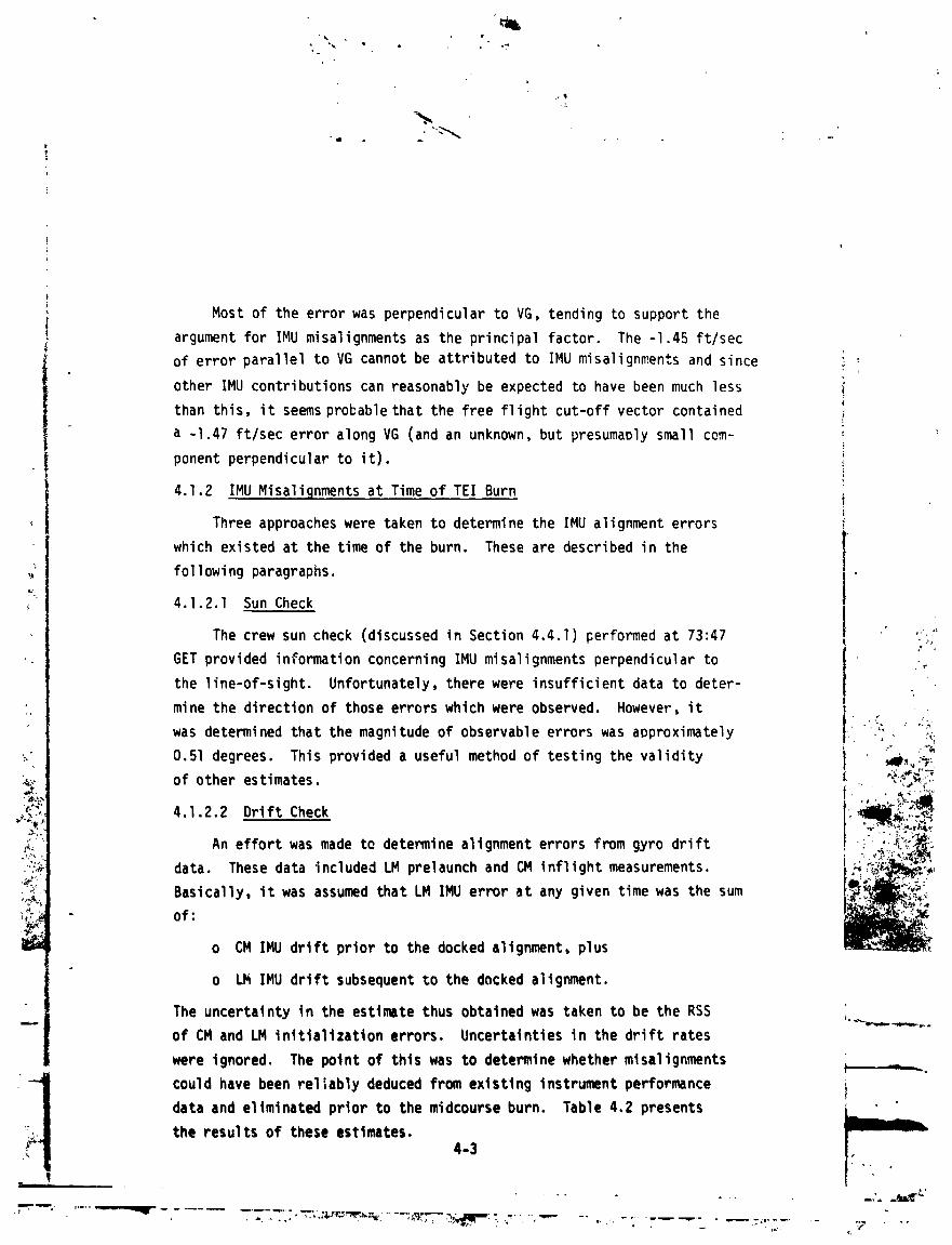
Most of the errorwas perpendicularto VG, tending to supportthe
argumentfor IMU misalignmentsas the principalfactor. The -I.45 ft/sec
of error parallelto VG cannot be attributedto IMU misalignmentsand sincer
other IMU contributionscan reasonablybe expectedto have been much less
than this, it seemsprobablethat the free flight cut-offvector contained
a -I.47 ft/sec error along VG (and an unknown,but presumaolysmall com-
ponent perpendicularto it).
4.1.2 IMU Misaliqnmentsat Time of TEl Burn
Three approacheswere taken to determinethe IMU alignmenterrors
which existedat the time of the burn. These are describedin the
followingparagraphs.
4.1.2.1 Sun Check
The crew sun check (discussedin Section4.4.1) performedat 73:47 " "?
GET providedinformationconcerningIMU misalignmentsperpendicularto _
the line-of-sight. Unfortunately,therewere insufficientdata to deter-
mine the directionof those errors which were observed. However,it
was determinedthat the magnitudeof observableerrors was approximately : , _p
0.51 degrees. This provideda usefulmethod of testing the validity , wlk,,_:_of other estimates. - _
4.1.2.2 Drift Check ..,,_:._._._,_"-'_"
An effort was made to determinealignmenterrors from gyro drift _ _::_,data. These data includedLM prelaunchand CM inflightmeasurements. _f_,_,
_l_Ji_i_,;_-__" _'_"time theBasically,it was assumedthat LM IMU error at any given was sum :_.,_)_y
of:o CM IMU drift prior to the docked alignment,plus _-,_,-_,
o LM IMU drift subsequentto the docked alignment.
The uncertaintyin the estimatethus obtainedwas taken to be the RSS
of CM and LM initializationerrors. Uncertaintiesin the drift rates
were ignored. The point of this was to determinewhethermlsalignments
"i could have been reliablydeducedfrom existinginstrumentperformancedata and eliminatedprior to the midcourseburn. Table 4.2 presents
the results of these estimates.4-3
• . +
.. .,. ,,_ .... _'
"--" _ -...........--T_'L_'_._',F_ ......._7_- :_ _ ,,.......... ' ".............- :'_'._ - :7 ....<,
1973017939-048

From the table it can be determinedthat the magnitudeof misalign-
ment estimatedfrom drift data is 0.60 degrees,wit_ a l_ uncertainty !
due to initializationof +.28. Almost all of this would have been
i visible to the sun check. Thus, the magnitudeof the predictederror
! agrees ratherwell with that observedin the sun check, and the dis-
-_ agreementlies well within the boundsof predicteduncertainty.
| 4.1.2.3 VelocityError Check
I Once the velocityerror at TEl cut-offwas determined,it was
possibleto determinein two stepsa unique set of alignmenterrors whichi
_"I satisfiedthe constraintthat the sum of the squaresof the error angles
i was minimized. Step one consistedof determiningthat componentof
J velocityerror perpendicularto the veloci,*ygained vector. This was _.'
done because IMU misalignmentscan be shown to produceonly perpen-
dicularerrors. The procedureand resultswere describedin Section
4.1.I.2. The second step consistedof solvingfor a "minimum"set of
error angles. The cons_rair,t equationsare: - _ •_:
Minimize .*• __= I_12,subjectto ._,:,_.,
_.i (VG) x (_) __Vnv , where
__: the vector of error angles -_.._--,,
_:i_::the velocitygained in the burn - - ?_L.._i._
__VnV:that componentof burn velocityerror perpendicular D_,_._
The solutionobtainedfrom theseconstraintsis: " _{_"
:: _ (VG)
Applying this relationshipto the quantitiesgeneratedin Section 4._.1 _ --.-.....
yields: _
± = [-.062;-.035; +.344]degrees *,.
I;!= .351 degrees _
4-4
.............._.:..... ". _,_._r_ :" "_" ' "
1973017939-049

It must be understoodthat, assuminga correctmeasure of _n' these are
the errorswhich generated_V (moreover,most of this would have beenvisible in the sun check). However,these errors do not necessarily
reflecttotal IMU misalignment. Platformmisalignmentsabout VG would !
generateno velocityerror. Consequently,that componentof total IMU
, misalignmentwhich was about VG cannot be determinedby an analysisof
AV . It is to be expectedthat total IMU misalignmentmagnitudewould_ -nl be no less than .351 and would probablybe greater. The discrepancy
would arise from the irresolvablecomponentabout V__GG.
1 A patternof reasonablygood agreementemerged from the above error
estimatesas evidencedin the summarybelow" _L.
Source of Estimate __¢x __°x ¢y y° Cz _z _I¢I _j_
Sun Check .............................. 0.51 .....
Drift Check -0.26 +_0.24 -0.07 +_0.14 +0.54 +__0.040.60 +_0.28 ..-.
VelocityCheck -0.06 ...... 0.04 ..... +3.34 ..... 0.35 .......
Agreementbetween the threemethods in the Z component,and in magni- _ ::'"• %
tude, is fairly good• Also, agreementin magnitudeand in the "X" and "Y" ' " "J
estimateslies within the Io uncertaintyband. - -_._ ,_.
4.1.3 PIPA Bias and IRIG Drift ." . " :-c:_.:
LM PIPA biases were stable throughoutthe periods the LM IMU was ,-_.,'_'i_iC_"._=:c_activated. The LM IMU was turned on for the first time shortlyafter L _c,,_T;
the CSM incidentand remainedpoweredup until after the TEl burn. Heater _'_'_,_
power was always maintainedin the system. The systemwas activated ___:_for the second time at 134 hours GET in preparationfor the MCC 4 maneu-
tver. Samplesof PIPA bias during the periods the systemwas activated
indicatedthe followingmean values and data variations. ,
| 4-5
|I I I I i • i . ill- i ,..l_iL
....." .........-'_ -............T......T."- _'_..............-_ _,_.:c,._,_...................... .. ,-----....._ ,,.,_....
] 9730] 7939-050

°
Numberof Sample*PIPA Samples Mean Value StandardDeviation
X Ig 1.494 cm/sec2 0.014 cm/sec2
i Y 19 -1.427 cm/sec2 0.038 cm/sec2
'_ Z 19 1.573 cm/sec2 0.011 cm/sec2
*Design SpecificationUncertainty(IJ) = 0.2 cm/sec:.
Insufficientdata were availableto evaluate IMU IRIG drift on this ]
mission. However,based on the small values of LM IMU misalignmentat
the time of the TEl burn determinedfrom the error separationstudy in
_ Section 4.1.2.J,it can be deduced that the gyro drifts were small and
• easily within the 3_ design uncertaintyof 0.09 deg/hr.
_IT.._,LOT4.2 LM DIGITAL _' '_'
An analysisof the DAP cor_rolfunctionsduring the Apollo 13 mission
was performedto verify proper DAP performance. The followingitems were ,_
considered: .',!
, o The MCC 2 DPS free returnmaneuver
o The TEl (pericynthion+ 2 hour) DPS maneuver :_
o The maneuver to the LM PGNCS PTC attitude. _'._'_-"_. ___,'_
o The attitudehold capabilitvof the LM DAP in the , • _,o_,_LM/CSM and LM/CM configuration. _WI_,._.I
o lhe automaticmaneuver capabilityof the LM DAP in , _,_the LM/CSM configuration. ' _,_*_
m_ "-,.._.
o The manual maneuvercapabilityof the LM DAP in the c_,_/:'_:Jk_,,LM/CSM and LM/CM configuration• . _*,_
4.2.1 MCC 2 DPS F,'eeReturnManeuverAnalssis
A four jet, 8.01 second ullagewas initiatedprior to the MCC 2 - |DPS burn at 61:29:36.06GET. DPS ignitionoccurredat 61:29:42.84GET. (
::, Prior to the DPS burn the U-V rotationaljets (i.e.,X translationjets)_.. were not manually inhibitedas is usuallythe procedure• Manual throttle-
• up from 11.9% to 36.8% occurred at approximately 61:29:50 GET. Program
sequencingprior to and during the burn was nominal, Manual throttle-upmmmmm
4-6
........._.. __-_ .--_,-..,................._-. ........
] 9730] 7939-05]

i
to 36.8% was nominaland requiredAV of approximately38 ft/secwas
achieved. The burn residualswere 0.2, O, and 0.3 ft/sec for the X,
Y, and Z components,respectively. No manual nullingof these residuals
was necessary. Table 4.3 shows the magnitudesof the maximum estimated
rates and the rate gyro signalmaximum values during this burn. The
lo_'magnitudesindicategood burn performanceand no discernible
sloshingeffects. Little or no slosh would be expectedsince the APS
and SPS were fully loaded duringthe burn and the DPS was fully loaded
at the start of the burn. Table 4.4 shows the magnitudesof the maximum
"' attitudeerrors and rate errorsobtainedduring this burn. Figures4-I,
4-2, and 4-3 show the phase plane plots for the P, U, and V axes, re-
spectively,for the MCC 2 burn (RelationshipbetweenP, U, V and X, Y, Z
" axes is shown in nomenclature). These plots indicatenominal DAP perfor-
, mance. Table 4.5 shows the RCS fuel consumptionrequiredto maintain .
attltJdecontrolduring this burn. The total RCS propellant(excluding '_
ullage) requiredduringMCC 2 was 12.go Ibs. Figures4-4 and 4-5 show the
pitch and roll GDA positionsthroughoutthis burn and indicatesatisfactory
" GDA performance. Duringthe manual throttle-upfrom If.g% to 36.8%, the .
effectsof a transientdue to the complianceof the DPS gimbal system can
. be seen. This complianceeffect results in the GDA's driving in + pitch "*i,_...
_- " and a - roll direction• After relievingthis compliance,the GDA movement ,
':_ is as expected in trying to track the c.g. iiliI_,.._=
4•2.2 TEl DPS ManeuverAnal_fsls -.o.-_,_"
Prior to the TE! hurn, Jets 6 and 14 were used for a two jet, ll.l _":-
;_ second ullagewhich began at 79:27:Zg.43GET. DPS ignitionoccurred _ -,_.;at 79:27:38.30GET. Prior to the burn, the U-V i_tationaljets were __!
manually inhibitedas requiredby the preburn checklist• A nominal F_
I manual throttle-up from 11.4% to 37.7% Occurred at approximately
79:27:45 GET. The automatic throttle-up to 93.9% occurred at approxi-
I mately 79:28:05 GET, The burn residuals were 1.0, 0.3, and 0 ft/sec for _----------the X, Y, and Z components, respectively. No manual nulling of these
residuals was performed. Table 4.6 shows the magnitudes of the maximum
estimated rates and the rate gyro stgnals maximumvalues during this burn.
._.... 4-7
_,, ,._. , ..,
....."_ ................._ . . .-'."".':.i_-_"-_o-......_"_:.......-_ "----_, ,-.. .:
1973017939-052
The values indicatenominalperformanceand very sm_ll slosh effects,
as would be expc .edwith the propellantloadingsthat were present,
i.e.,APS full and DPS and SPS nearly full. Table 4.7 presentsthe
magnitudeof the maximum attitudeerrors and rate error which occurred
during this burn. Figures 4-6, 4-7, and 4-8 show the phase plane plots
for the P, U, and V axes, respectively. The time period plottedbegins
lO secondsbefore ullage and extends 20 to 30 seconds beyond the start
I of aut_,;aticthrottle-up. The plots indicatenominalDAP performance.The U and V axes plots indicatetwo large excursionsbeyond the dead-
_ band. In each case, the first excursionis smallerand is associated
with manual throttle-up. The secondexcursionis associatedwith auto-
matic throttle-up. TabIP 4.5 presentsthe RCS fuel consumptionrequired
to maintainattitudecontrolduring the burn. The total RCS propellant
, (excludingullage)was 4.90 Ibs (all expended in P-axis contrcl).
I Figures4-9 and 4-I0 show the pitch and roll GDA positionsfrom DPS
ignitionthrough the automaticthrottle-upmaneuverand inOicatenominal
GDA performance. Some concernwas expressedabout the fact that the roll
, GDA drove approximately-I.3 degrees from its initialoositionat the
start of the TEl burn. This appearsto be nominalbehavior causedbyo,
relievingcomplianceand perhapscorrectingfor some mlstrim, The
_ ; followingfacts are known.
"_, _ .. j a) The preferreddirectionfor complianceis in a "+ pitch"_ and a " roll" direction.
_. b) Complianceappearsto be highly non-linearand transient_'" effectscannot always be observed•
.. _ c) Previoussimulationsusing the now-inoperativeMSC bit-
_, _ , -L by-bit simulationhave shown similar transientcompli-ance effects on all tests.
d) For the MCC 2 bun_ the pitch GDA drove +1.05 degreesduring throttle-up from 11.9% to 36.8% and the roll
_-s ._ GDA drove -0.75 degree during throttle-upfrom 11.9%to 36.8_. These effects were apparently due to theeffects of compliance.
-- _'" _'-L: e) At the end of the MCC2 burn both the pitch and rollGDA's were driving in a positivedirectionIn tryingto track the c.g._:_
__/ 4-8
I
1973017939-053

; f) For the TEl burn the pitch GDA drove +0.435 degreei during throttle-upfrom II.4% to 37.7% and the rollj GDA drove -I.335degrees during this throttle-up
! period.
i g) The root-sum-squareGDA change due to compliancewasapproximately1.29 degrees for the MCC 2 burn and
! 1.402 degreesfor the TEl burn,
h) For the TEl burn the pitch GDA showed no noticpablechange during throttle-upfrom 37.7% to 93.9%. Theroll GDA drove -I.245degrees during this throttle-upperiod. The root-sum-squareGDA change of 1.245 degrees iagrees closelywith the previouslydiscussedvaluesof1.2g degreesand 1.402 degrees.
Evaluationof the facts discussedabove leads to the conclusionthat the
GDA behaviorfor both the MCC 2 burn and the TEl burn was nominal.
4.2.3 ManeuverTo PTC Attitude
The difficultiesencounteredin maneuveringto the PTC attitude
subsequentto the TEl burn promptedan investigationof the torques
associatedwith each LM reactioncontrol jet and with the various
rotationaland translationalfiring policiesavailablein the LGC. I
This investigationincludedthe effectsof impingementforces on the _,:_,_
-; plume deflectors. "'""' '_
_,.,_ At the time of the maneuver,the best estimate of LM and CSM _I_ 7_
_" weightswere Z5666.2 Ibs and 62489.7 Ibs, respectively,or a total Jweight of 88155.9 Ibs. This value was referredto in the SODB ,_,_d,(Reference2) which definedthe combinedvehiclec.g. locationin the _t _,
CSMbody frame as follows: X, • +1049.38 inches; YA _ +2.49 inches;
and ZA - +3,59 inches. These valueswere obtainedby linear inter- _:polation of the values recorded in the $ODB. These data were used to
transform the c.g. location into LM body axes.
!
4-9
,.;. _ _ ...................._ ' :._._ .... _ ,'-_"" _ _ ....... . -
,_-%I
1973017939-054

r_
.... %
!A"
i The SODB also definedthe locationsof the points at which the re-
action ccntroljet forcesare applie_. The locationof the impingementforceson the plume deflectorswas definedby Reference3. Based on the
locationof each of the sixteenreactionjets with respectto the c.g. and
the thrustvector,the torque for each jet was calculated. Using the data
from Reference3, torqueswere calculatedfor the impingementforces result-
ing fro,,,each of the downwardfiring thrusters.
The GSOP (Reference4) gives the iet policiesto be used in the
varioustranslationand U-V rotationalmaneuversthat can be performed.!
i Tables 4.8 and 4.9 indicatethe torqueswhich result from the use of ,- each of these policies. In addition,there are possiblejet policies
"_ "4 !• associatedwith Q and R axes rotationsin the minimum impulsemode.
" i These are not defined in the GSOP However,the various_._!icieshave
been determinedand the torquesresultingfrom each policy are defined1. in Table 4.10.
i The maneuveringproblemreportedby the astronautsprimarilywasa cross-couplingeffect betweenthe pitch (Y or Q) axis and the rollI(Z or R) axis. No downllnkdata is availablefor the periodof thei
( maneuver. However,certain assumptionscan be made. |
( a) All jets were functioning;this impliesthat primary
I jet-policieswere in effect at all times. _
"_ I b) The maneuverwas conductedmanuallyusing either: _:;..ql_
_' l) Y-axis and Z-axis translationcommandsthrough _'"the TTCA; or
|',o 2) Three-axis(X, Y, and Z) rotationalcommands _L_.._.
_ through the ACA. _'i"?:"_c6":-._; Examinationof Table 4.8 reveals _hat Y-axisand Z-axis translationcom- i':_,__
mands produceonly minor cross-couplingaround the yaw axis. Pitch-roll _"
cross-couplingis non-existent. Examinationof X-axls rotationalpolicies i
in Table 4.g revedlsthat primary jet-policies,using e_ther four jets
or two, produce only X-axts rotations. Data for Y-axis and Z-axts rota- _-- ....
tions are shown in Table 4.10. The use of four jets for any rotational
maneuver produces very minor cross-coupling. However, the GSOP_tates 4--------.
that pitch and roll maneuvers in the minimum impulse modewill be
--,r I
4-10
-...-;,..._....... -_ ..... .._ ............ ._._ ._ / .-
1973017939-055

accomplishedwith two jets. Examinationof the jet-policieswhich use
two jets revealscross-couplingtorquesthat have the same magnitudeas
the primarytorques. This occurs becauseeach of these jet-policies
employsone downwardfiringjc'_. The resultingimpingementforce acts
equallyabout the Y-axisand the Z-axisusing the long X-axismoment iarm. The result is to reduce the primarytorque by a factorof two
and producethe large cross-couplingforce.
Althoughdata for this time period is lacking,examinationof data
for a later periodrevealedthat these rotationalfirings took place.
" Data indicateda +R (+Z) rotationalcommandat _37:22.4_.616and -(I(_v)I
._ rotationalcommandat 137:23:01.616. Examinationof jet firings data
showedcorresponding60 millisecondfiringsof jets 5 and lO at 137:22:50.434
and of jets lO and 13 at 137:23:01.234.Analysishas shown that jets 5
and lO producea pr-imary+R torqueand jets lO and 13 producea primary -Q ." .-:.
torque. Since two jet Y and Z axes torquesoccurredat these times, it ;_"
is not unreasonableto inferthat they also occurredduring the maneuver
to PTC attitudeand that they producednot only the primarytorque but a l -
cross-couplingtorqueof equalmagnitudeas well. If the THC was used _" "_i;.....
to performmaneuversin the LM/CSMdocked configuration,no unexpected , _J:_
problemsshouldbe encounteredif the crew is familiarwith this type i _, __;__'_of operation. However,use of the RHC or the MIC can produceresults i' _ { _
which would be very unexpected. _-'_"T°'6
It is recognizedthat the above analysisrepresentsonly one of a number ..._,_z__,,_%
of possibleexplanationsof the controldifficultiesencountered. Another ,_"_,.:.,_._
probablesourceof difficultyis the fact that the FDAI was powereddown •_ ......
during the maneuver. Withoutthat source of attitudeinformation,it was __
necessaryto monltorattitudeby observinggimbal angles displayedon the
I DSKY. Becausethe spacecraftyaw axis was not coincidentwith that ofthe platform,eithera pitch or a roll commandwould cause a change in both
of the correspondinggimbalangle displays. That this was a factor is sup- _'--_--------_
portedby the fact that, after the vehicle'sand platform'scorresponding
axes were broughtinto closeralignment,passivethermal controlwas estab- ! _ -_
fishedsatisfactorily• i
4-ll
, ...... _k_ _ '
1973017939-056
e
-. ", °
4.2.4 DAP Controlof the LM/CSM Configuration !
DAP attitudecontrolwas evaluatedfor periodsof attitudehold, ;.
i i'. and for periodsof automaticand manual maneuvers. The availabledata iwere for a 5 degree deadb_nd. Figures4-11, 4-12 and 4-13 (P, U, and
V axes, respectively)presentboth periodsof auto maneuverand attitudeS
hold. The auto maneuverperiod was 61:25:17to 61:25:20GET. The atti- itude hold periodbegan at 61:25:21GET and _as plottedfor approximately
2 minutes. This periodprecedesthe MCC 2 maneuver and nominal DAP
, performanceis indicated. An auto maneuverprior to the TEl burn is
,- presentedin Figures4-14, 4-15, 4-16 (P, U, and V axes, respectively).
The maneuverbegan at 79:21:43and was terminated3 secondslater.._ Nominal DAP performanceis indicated. A five minute period of attitude
hold subsequentto this maneuver is plettedin Figures4-17, 4-18, and
4-19 (P U and V axes respectively_ The period coveredis 79:22:00 "-_
to 79:27:00. The U and V axes phase _lanesare plottedfor the entire :,
time period. The P axis was functio_.,ngin a much faster duty cycle of
which one completecycle has been plotted. Manual maneuverswere per-
formed in the minimum impulsemode where the desiredCDU angles are _ ._
set equal to the actual CDU angles. Since no attitudeerrors exist, wle_v
it is not possibleto generatea meaningfulphase plane plot. However, .,"_._
it was determinedthat the rate errorsdid not exceed the deadband " '_,_;_.
limits. . ; _._:_:
4.2.5 DAP Controlof the LM/CM Configuration _,:-Ci-_!i_'_;i._
attitudecontrolwas evaluatedfor a time period that contained )Yj,_C,'.'{_I.'_DAP
both attitudehold and a manual maneuver. The P, U, and V axes phase _j_
plane plots are presentedin Figures4-20, 4-21 and 4-22, respectively. __
The attitudehold period presentedbegan at 140:49:12GET and terminated
at 140:51:25GET at which time the manual maneuverbegan. Since thei
manual maneuverwas performedin the minimum impulsemode, the attitude _._,....error remainedapproximatelyzero as shown by the three figures.
)
4.-12
. ,__,._',--
"_"" -" ..... _ ...... _ ........................... , ,-m'_'_,_e,:_,,',._'_-,,.,.... _"-- _,_tlr.._ .......... -.- ,,, ......... " _ -" " '........_ "--'- " _'- ............... 7 .....
1973017939-057

4.3 LM ABORT GUIDANCE SYSTEM
Investigation of AGS performancewas conductedwith the objectives
uf:
o Determiningthe stabilityof AGS sensor static errors i(accelerometerbias; gyro static,or bias drift).
o DeterminingAGS sensor dynamicerrors from comparisonsof AGS and PGNCS measurementsduring the TEl burn.
o ComparingAGS and PGNCS measurementsof velocitygainedand vehicleattitudeduring midcourseburns•
aL
After the ServiceModule LOX tank incident,four burr,s were made to
return the spacecraftto earth as quicklyand safely as possible. The
first and second burns were made under PGNCS controlwith the LM DPS;
the AGS was poweredup for the secondburn and used in the "back-up" _-L',
mode in case of PGNCS failure The AGS was used to performthe last
two burns, a DPS burn of 7.8 ft/secand an RCS burn of 2.8 ft/secS
I 4.3.1 Burn Analysis ;.
I TEl (AGS in Follow-Up) .: " ._
i The second LM DrS burn was at approximatelyinitiated 79:27:41
followingan X-axis RCS burn for ullage. This burn was performedwith ._ml_'_,_PGNCS control and the AGS in follow-up. Although the AGS was not tar- ..,_---_.:_;
i geted for the maneuver,its indicationof sensed velocityand attitude ,_._T_C_:
i were availableto confirmsuccessof the burn. After AGS power-up, -"-"* "_a Body Axis Align was performed. Throughoutmost of the burn, the astronauts ._,__a_._-/:\_
monitored"x" sensed velocityin body coordinateson the DEDA and PGNCS sensed _:,i"__' ._w--"_,..,_,__, _.velocityon the DSKY. These velocitiesare plotted in Figure 4-23 and _!,
indicategood agreementbetweenthe AGS and PGNCS. !' I| Followingthe burn, AGS power-down(includingheaters off)began at
approximatleylg:51:00. _" -_,_,--,-.-,,
4-13
"_'""_':" '......."'muir" ............................-'- "r_";::,-_-_--........._.........-_-_-i-_' ..... _,_...... , . ._..... ".;
] 9730] 7939-058
!
MCC 3 (AGS Controlled- DPS)
This burn, a small maneuverto increasethe entry flight path#.
angle, was performedunder AGS control. Plots of sensed velocities
are shown in Figure 4-24. Since the burn was insensitiveto burn time ;
cut-offerrors and attitudeerrors, the primaryburn rule was to avoid :
excessiverates (more than IO leg/sec)about any axis.
l 'Systempower-upfor the burn was initiatedat approximately
104:40:00. At approximately104:58:20,the ASA temperaturehad risen i• "_ _ above ll5 degrees F and the AGS was activated.
-. DPS burn time was voiced up as 15 sec althoughthe astronautswere
" told to shut-downafter 14 sec to avoid an overburn,which would require
an RCS trim, impingingon the commandmodule.
Figures4-25, 4-26, and 4-27 show the attituderates and attitude ;•_errors. Rate and attitudeerror data indicateno appreciabledisturb- ..
ances since all three channelsappearedto be in normal limit cycle
operation.
Becauseof the plannedearly shutdown,the maneuverwas a slight
underburn, An RCS trim burn was performedapproximatelyone minute r',_•<:'• _4 .>
< P later, increasingthe burn AV by 0.2 ft/sec to 7.8 ft/sec. Subsequently, _._
_ the AGS was powered-downincludingheater power off.... kL - * +'
+"_" MCC 4 (AGS Controlled- RCS) ;C_
'_<3_</ PGNCS and AGS were powered-upat approximately136 hours and the _"
,_,,,/.. maneuverto burn attitude for this midcoursecorrectionwas with the . ._.'_'T_.:_ _i PGNCS. _ ',
In Figures4-29, 4-30, and 4-31 comparisonsbetweenthe AGS and
PGNCS indicatedattitude=are made for the period of manual maneuver-
ing to acquire the appropriatespacecraftattitudefor MCC 4. (An
AGS to PGNCS align precededthe re-orientation.)Followingacquisitionof
the burn attitude,Guidance/Controlwas switchedto AG$. ,_._,
c |_
._ _ : 4-14
...._ ........... "_ ...................._ ......_"'_'i_._'m'_' .........o-_-_......._ - _ , - --,_-,......... _ _
1973017939-059

i The burn was initiatedat approximately137:39:52with the X-axis RCS.|
The DSKY was used Lo observe the accumulatedvelocity. After about 23
seconds,the RCS was turnedoff after achievinga _V of 2.7 ft/sec. A
• partial trim was effected 15 sec later,bringing the total AV to 2.8 ft/sec.
This was short of the desiredvalue of 3.1 ft/sec,but was indicatedasacceptableby the ground. The _V's are shown in Figure4-28.
i No attitudecontrolproblemswere noted during the burn, with manual _pitch and roll providedby the TTCA and AGS yaw controlby the AGS _t_itude
hold mode as seen in Figure4-32.
"_ 4.3.2 Sensor Performance(ASA 023)
4.3.2.1 AccelerometerErrors
Free FliBht Performance- Free flight accelerometerstatic bia_ data
were obtainedfor two time periods,pre-TEIand post-MCC4. Bias esti- -,..
mates obtainedfrom these data appear in Table 4.11. Table 4.12 compares
the shifts undergoneby this parameterafter prelaunchcalibrationwith
standarddeviationsof this shift. The AGS CapabilityEstimateone sigma
values result from data samples taken from a number of AGS systems;as such, -.
* they are representativeof generalAGS performance. The table revealsthat _:__dlP•_.
staticbias performancewas easily within lo of AGS CapabilityEstimate. "VC_'._This is excellentperformancein view of the fact that the ASA dropped ' _' "
23 degrees F below the specifiedminimum (60 F) during the 24 hour period _I_-_,_,i_
in which it was shutdownprior to the TEl burn. ,,. ,,_•.,_,
PoweredFlight Performance- The TEl burn was the only one performed _Ill_"_m_"?_,duringApollo Mission 13 of sufficientdurationand thrust to permit _._,_.,,:_
estimationof AGS dynamic sensor perf_'rmance.Figures4-33, 4-34, and 4-35 __!]*_'*"
show the accumulatedsensedvelocityalong the body axes. The _V magnitude _F__.,
was about 860 ft/sec.
Accelerometererrors were found from AGS/PGNCSsensed velocity
comparison_. The PGNCS velocitieswere compensatedfor known static ' "
4-1s I
r
, "'_ .......-----._r ...................._ "._'::":__-''_r'"......_'......_" ._: ...... ----....................... .'_ ,'_.....
1973017939-060

ibias errors, interpolatedto AGS times, transformedto body coordinates,
and subtractedfrom the correspondingAGS velocities. The differences i
are shown i..Figures4-36, 4-37, and 4-38. Since PGNCS gimbal angles
_. were used to transformthe velocities,these differencesreflect only ,
accelerometererrors (plus noise due to AGS downlinkand PGNCS gimbal angle
quantizations). -i
i The estimatesof dynamicand total accelerometererror are listed in i
Table 4.13. The total errorswere derivedwith a digitalcomputerpro- ,
'! gram which determinesa set of "best"AGS errors for the purposeof mini-; . mizing the AGS-PGNCSvelocity residualsin a least squaresse,se. The |
•-. _ dynamicerrors were obtainedby subtractingthe staticbias (measuredover
_" i a 15 minute intervaljust before the burn) from the totals. Table 4.15
' i presentsratiosof the shifts (from prelaunchvalues) in these parameters
_ to shi_*s predictedby the ASA 023 error model. The table shows that all ._."""of these errorswere within the error model 20 limits. Plots of the velocity
residuals,compensatedfor the recoverederrors, are shown in Figures4-39,
4-40, and 4-4],
4.3.2.2 G_ro Errors " _"
Free FliqhtPerformance- Free flight gyro staticdrift data were _._,_-?C"
obtainedduring two time periods,pre-TEIand post-MCC4 (the interval '-om .":_ .qZ
T-_" 140:29to 140:51GET). Drift estimatesobtainedfrom these data appear n -_._,o..;,:_.,I_'?__iTable 4 II X channeldata were noisy and interpretationwas correspondingly " )i-_''_-_
difficult. Thus it was necessaryto specifya range of possibleperformance ,_.-.._.:_.
values. Instrumentperformancewas within I_ AGS CapabilityEstimate _411_':'__,;'_:,tolerances,so that it may be said that the static drift performancewas _-_)':!_
quite satisfactory.
Powered F..li_htPerformance- Gyro error was obtainedfrom AGS/PGNCS
attitudedifferencesobtainedjust before and during the burn. These
differencesare shown in Figure 4-42, 4-43, and 4-44. Because of
relativelyconstantinertialattitudeand thrust level, the effects
of dynamicdrift, scale factor error, input axis misalignment,and mass
4-16
1973017939-061

i unbalance cannot be separated. However, since the burn was performed
! in the "attitude hold" mode, the effect of a significant scale factor
! error or input axis misalignmentwould have been negligible. Because
of the low thrust level (about0.I g) mass unbalanceprobablycon-t
i tributedvery little error. Thus most of the error was attributedtogyro static and dynamicdrift. The total errors were determinedby
measuringthe slopesof the attitudedifferencesduring _he burn.
The dynamicerror was obtainedby subtractingthe static values from
the totals. The dynamicand total errors are presentedin Table 4.14.
Listed in Table 4.15 are ratiot of the shift_ in measuredparameters
to their l_ values. None of the errors exceeded2o with respect to ASA 023
prel_unchperformance.
4.4 LM OPTICALALIGNMENTCHECKS
4.4.1 Sun Check for TEl Alignment
Shortlyafter the servicemodu!_ LOX tank incident,the crew per-
formed a docked LM ]MU alignmentto the CM IMU. At 73:47 GET a check -i.
of this alignmentwas performed. At the time of the check,visibility
through the c#tical instrumentswas eYtremelypoor due to an agregation
of debris surroundingthe spacecraft. In addition it was desired that
- | maneuveringbe held to a minimum to conserveRC_ propellant. Conse- ,
I quently the decisionwas made to limit the initialcheck to one celestial i' _I_ 4_
body. The sun was chosen becauseof the visibi_.y conditions. The i" "_'_
check consistedof oointingthe AOT line.-of-sighttoward the LGC calculated _ _.";_m'_,
sun directionand then noting the approximetemagnitudeof the offset. : -._ _...._
The LGC was placed in P52 and routine R52 (Auto Optics Positioning)was : ;_._
used to establishthe LGC-estimatedpointingvector. The FDAI attitude _"__"
error displayswere used to hold this spacecraftattitudewhile the __, _c_,_'
positionof the sun in the fieldof view was determined. It was deter- __,
mined on the ground that the solar disc would subtendapproximately __
one-halfof a degree in the AOT field of view. From that fact and the
observedsun image the crew determinedan image (and thereforean IMU)
misa_ignmentof approximatelyone-halfof a degree in an undetermined ,--_....
direction. Since this single target optical check could not resolve
errors about the line-of-sight,no estimateof posslblemisalignmentsin , . -- _.
that direction was obtained• The mission rule established for this
4-17
, , I ...... _._ _"
1973017939-062

check was that any observed_:ror of less than one degreewas tolerable.
No effortwas made to correct the error observed,or to determinethe
error about the line-of-sight,prior to the TEl burn.
) In conductinga single target alignmentcheck such as this it is import-! ant to select a line-of-sightwhich reveals those alignmenterrors of con-
sequencein subsequentpoweredflight phases. More explicitly,it
I shouldbe chosen to measure all misalignmentshaving a significantimpact
on trajectoryparametersof importanceto a safe re-entry. One very
crucialparameteris entry flight path angle, and during the deep space
! phasesof transearthflight this is governedlargelyby inplanevelocity
I to the earth centeredradius vector. The sun wasperpendicular an ex-
_ I cellentchoiceof targets For detectingmisalignmentsas they effected: Apollo 13's post-TElentry corridor. This is demonstratedby the
; /_d. _, resultspresentedbelow:
" Let , = entry flightpath angle
V = velocityerror in the directionwhich effectsflight path anglet
V = velocitygained in the TEl burn
Unit (LO__SS)=the unit line-of-sightvector to the sun at thetime of the sun check,
CLOS= II,IUmisalignmentabout the line-of-sightvector
•_ _ Then _' = i__: ,CLOs _T • (_ x Unit LO__SS= -.088
:' o This quantity is unltlessand serves to show that a one degree misalign-
_ ment (for example)of the IMU about the line-of-slghtvectorwould have
,_- produced only -.088 degrees of error in the entry angle of the post-TEI
:]"_ L trajectory. Restated,entry flight path angle errors were extremely
insensitiveto misalignmentswhich the sun check could not resolve.
Conversely, _ was quite sensitive to those errors which cou_ be
observed by the sun check, as illustrated below:
,_ -- - -10., where _n is mtsaltgnment ob_e_ed in |
/ _ the sun check.
......... ..... 4-18
.,,._, . _ ..............................._ ,'_:,,",_'_'-_,....... , :--,,_,., _, _,...... ..- _ _ _ __ -. _ _ ----
i
1973017939-063
Gased on the above study, it is concluded that:
o the choice of the sun as the target for th;s optical checkwas an excell_ntone, and; i
o Compensativetorquingof the IMU to eliminatethe error ob-served in the sun checkwould have resultedin a much saferpost-TEltrajectory.
4.4.2 Sun/MoonAlignmentStar Angle Difference
During the time intervalfrom 134:45 through135:02of ground elapsed ,!
i time the Apollo 13 crew performeda P52 alignmentof the LM IMU. The
" "_ sun and moon (centers)were the optical targets. A star angle difference
_ of -l.12 degreeswas calculatedby routine R54, indicatinga very large
astronautsightingerror. However,a postflightinvestigationshows
the actual star angle differenceto have been approximately0.08 degree.
The LGC has an algorithmand associateaephemerisdata storedwithin i
it for computingpointingvectors to various celestialbodies,including
the sun and moon. For the star angle differencecalculations,this al-
gorithm is used and the scalar productof the resultingvectors isL
computed. The arc cosineof this quantityforms the LGC's best estimate
of the angle between the sightingvectors. The LGC also computesthe _,,_
" • angle between the measuredvectors,and these two anglesare differenced : "<_,"_,
_i-- to obtain an error (stored- measured)for presentationto the crew. _,.>'7"_,_
_,_ After the above mentionedApollo 13 sightings,the crew display showed _ t':,_,_.
_. an angularerror of -1.12 degrees. In order to check this value, the ,-, ,:m_,
'_'{ two angles and theirdifferenceswere recomputedindependentlyas _
, _ describedbelow. _ .-_: :_'_r_-,:_ Procedurally,the crew can make as many as five measurementsof each
_ vector. The _GC averagesthese measurementsand transmitsthe two aver-
" age vectors on the downlink. These veclors (unitized)togetherwith
tt_ time Intervalin which they were taken,are presentedbelow in
platformcoordlnates(beforerealignment). "....
4-19
.... _ ...... _ .... . ..... .%,_-.,..,,.,,_.......... ...... -_._ _ -... ,,.- ..... , -_
i 9730i 7939-064

tI Sun(134:45- 134:48) +._789816 -.00424996 +.58930660
fi Moon
(134:57- 135:02) -.16146112 -.02178924 -.98663840
The angle subtendedby these two vectors is 135.38degrees.
In order to determinethe actual subtendedangle at the time of
mark, two sourcesof data were used. The firstwas the NASA Apollo
Trajectory(NAT),from which a spacecraftstate vectorwas obtained
. "-_ for an epoch immediatelyprior to the sightings. This vector and time
. were: im_
Time: 17 April 1970, 09:50:00.00GMT (134:37:00.00GET) I
' X: -.2822BO44E9ft° .
Y: +.18416553E9
Z: +.83610975E8
X: +.533054E4ft/sec
Y: -.581689E4
Z: -.294957E4
.I This vector and the TRW HoustonOperationsPredictorEstimatorprogram T
were used to obtain spacecraft-centeredsun and moon vectors from the I_;"
_: most recentJPL ephemeristape (JPL DE6gD) at th( start and stop times of ._
_: .. each measurementinterval. These vectorswere then unitizedand averaged. _.,,,:_
- They are presentedin Basic ReferenceCoordinates. _._
J- -_ Sun X Y Z _:.
""" (134:46.5) +.89145748 +.41570609 +.18025559 . :_
Moon
(134:59.0) -.95321902 +.27595070 +.12338832
angle subtended by these vectors is 135.46 degrees. Therefore, the
The
-- . actual difference in the angles is seen to be 135.46 - 135.38 • .OB degree. ""_"
_ Therefore, an LGCcalculated angular discrepancy of -112 (08) • "1.20
_ is seen to exist and is attributed to the LGCephemeris data and software
.... ' " ' 4-20
" "'; ........ -" ................ : ..... :'." -':. _"_-"_.-." ..... s: ..... %.:_._.,-,_ ........ . -- ., _- .
1973017939-065
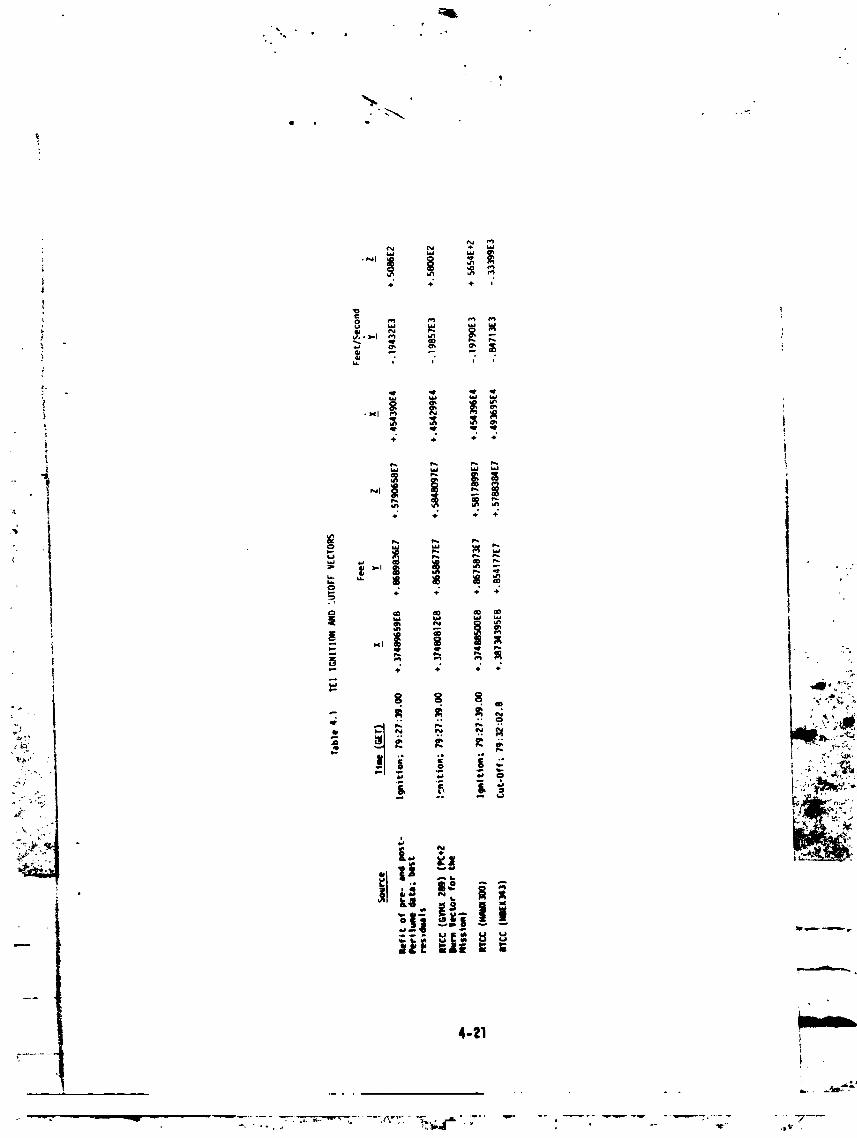
4-21
1 '• , ...... _
_ _ _ _:._ ............-- .- - -- _,_ ' _-."_'_T ........ _P_,"......... .m ,.-- ,_ - - -.. .... ._
] 9730] 7939-066
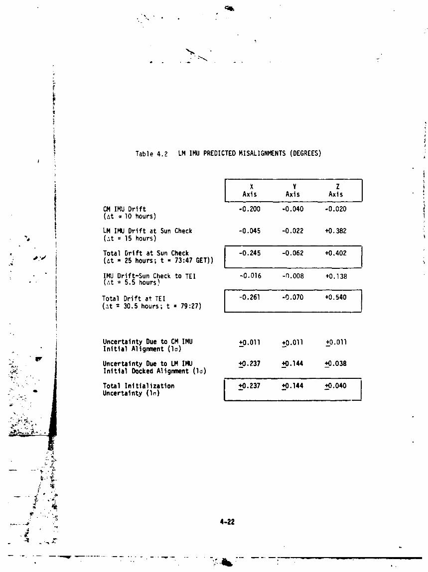
a • __ .
Table 4.2 LM IMU PREDICTEDMISALIGNMENTS(DEGREES)
i X Y ZAxis Axis Axis !
CM IMU Drift -0.200 -0.040 -0.020i (_t = 10 hours)
LM IMU Drift at Sun Check -0.045 -0.022 +0.382(_t = 15 hours)
• Total Drift at Sun Check I -0.245 -0.062 +0.402 I
•" #,'J (_t = 25 hours; t - 73:47 GET)) ! I
" IMU Drift-SunCheck to TEl -0.016 -N.O08 +0.138- • (_t = 5.5 hours)
Total Drift at TEl I ,-0.261 -0.070 +0.540(_t = 30.5 hours; t - 79:27) I
UncertaintyDue toCM IMU +0.011 +0.011 +0.011InitialAlignment (lo) - - -
_,, Uncertainty Dueto LM IHU _+0.237 _+0.144 +0.038._ Initial DockedAlignment (lo) -
':'"" "-',b / UncertatntyT°talInttialtzatton(l_) +0.237 +0.144 +0.040I
JI
_C =,,........,_ ,._ 4-22
.... ' ........• -" ...........................-. - ...... _._I_, ............i
1973017939-067

o *_ • o
•4J_ •
0 0
-- i
4-23
1973017939-068


Table4._ BODYTORQUESCREATEDBY TRANSLATIONALPOLICIESDEFINEDIN GSOP(Reference4)
BodyAxisTorque• f
Axis Jets Tx Ty Tz ,
i (in-lb) (in-lb) (in-lb)
I +x(+P)4 jet 2,6,10,14 0 -128.2 + 1559.2 ,
' _ 2 jet,sysA. 2,10 0 - 64.1 + 779.6 _
, 2 jet,sysB 6,14 0 - 64.1 + 779.6 iI
. !
-x(-P)
- 4 jet 1,5,9,13 0 -144 - 1740 I|':
2 jet,sysA 5,13 0 + 72 - 870
2 jet,sysB 1,9 0 + 72 - 870J.
i
,Y(,q)2 jet,prl* 12,16 + 72 i 0 -23,874
I jet,tack 16,15/16,7 + 36 0 -11,937
.; _ 12,3/12,11 + 36 ' 0 -11,937
....._ 2 Jet,pri 4,8 - 72 I 0 +23,874 C_::: 1 Jet, tack 8,7/8,15 - 36 0 +11,937_ . 4,3/4,11 - 36 0 +11,937
2 jet, pri 7,11 -870 +23,874 0
• I Jet, tack 7,817,16 -435 +11,g37 011,4111,12 -435 +11,937 0
*Prl - PrimaryMode..... -- **Tack • Tacking _ode
........ --';" 4-27
....................I
1973017939-072

E
. Table 4.8 (Continued)
, Body Axis Torque
Axis Jets Tx Ty Tz i4
(in-lb) (in-lb) (in-lb) i
-z (-R) I-_ • 2 jet, pri* 3,15 +870 -23,874 0
. I jet, tack 15,8/15,16 +436 -II,937 0;. # ,',J
, 3,4/3,12 +435 -11,937 0
- - +U (=+Y,+Z)
4 jet, pri 7,II,12,16 -798 +23,874 -23,874
2 jet, alt** 7,16 -399 +II,937 -II,937 "
II,12 -399 +ll,937 -ll,93Y-U (=-Y,-Z) '
... 4 jet, pri 3,4,8,15 +798 -23,b14 +23,874
_ "iW 2 jet, alt i 8,15 +399 -II,937 +II,937. ... , I 3,4 +399 .-11,937 +11,937
:_"-i ,." +V (=-Y +Z)
.... ' 4 jet, pri 4,7,8,11 -942 +23,874 +23,874
_, _,* 2 jet, alt 7,8 -471 +11,937 +11,937 _
4,11 -471 +11,937 +l'l ,937 _,.
-v(-+Y,-z) i4 Jet, pri 3,12,15,16 +942 -23,874 -23,874
2 jet, alt 15,16 +471 -11,937 -11,937 )
• t-- --- _ 3,12 +471 -11,937 -11,937 _"
p--- - -,- *Prl = PrimaryMode
• *Alt • Alternate Mode
',
.......=..................................., ,";,,,.._,_,- ......... .-:_ . - .............. . ..... ,-.......
1973017939-073

Table4.9 BODYTORQUESCREATEDBY ROTATIONAL
POLICIESDEFINEDIN GSOP(Reference4)
i BodyAxisTorqJe
, Axis i Jets'" TX Ty TZ: I
(in-lb) (in-lb) (in-lb)
+x(+P)
jet 4,7,12, +26,440 04 15 0
2 jet,pri* 4,12 +13,220 0 0
7,15 +13,ZzU 0 0 I2 jet,alt** 4,7 +12,749 +11,937 +11,937 :
7,12 +12,821 +11,937 -11,937
12,15 +13,691 -II,937 -II.937
/' 4,15 +13,619 -11,937 +11,937
-x(-P) I' 4 jet 3,8,11,16 -26,440 0 0
• 2 jet,pri 3,11 -13,220 0 0 ,
8,16 -13,220 0 0• 2 jet, alt 8,11 -13,691 +11,937 +11,937
II,16 -13,619 +11,937 -11,937
3,16 -12,749 -11,93/ -11,937 _ :i._
5 " 3,8 -12,821 -11,937 +11,937 ':""'_
_':' ; +U(= +v,+z) " a: :_._: 2 Jet, prt 5,14 + 196.4 + 6,236.8 + 6,187.9 ,_ ._;,__--_ 1 jet, alt 14 + 196.4 - 409.2 + 12.9 !: :
.u(..,,.z)' 2 Jet, prt 6,13 - 196.4 - 6,229.4 - 6,278.3
1 Jet, alt 6 - 196.4 + 344.6 + 766.7
13 0 - 6,574 - 7,045
* Pri • Primary _de
** Alt • Alternate _e i
{'-7" 4-29
...... _
1.q7 n17aqa_nTA

r
i
Table 4.9 (Continued)
I ...................
1 BodY Axis Torque - -_
I Axis Jets TX Ty Tz t(in-lb) (in-lb) (in-lb)
i +V(=-Y,+Z)2 jet, pri I,I0 - 166.4 - 6,229.4 _ 6,187.9
I , I jet.alt 1 0 6,574 + 6,175 }
I, 10 - 166.4 + 344.6 + 12.9 i
,,,,.,T -v(=,Y,-Z)• t
•_ 2 jet,pri 2,9 + 166.4 + 6,236.8 - 6,278.3
" " 1 jet,alt 9 0 + 6,646 7,045 _
2 + 166.4 - 409.2 + 766.7 i_-- .____
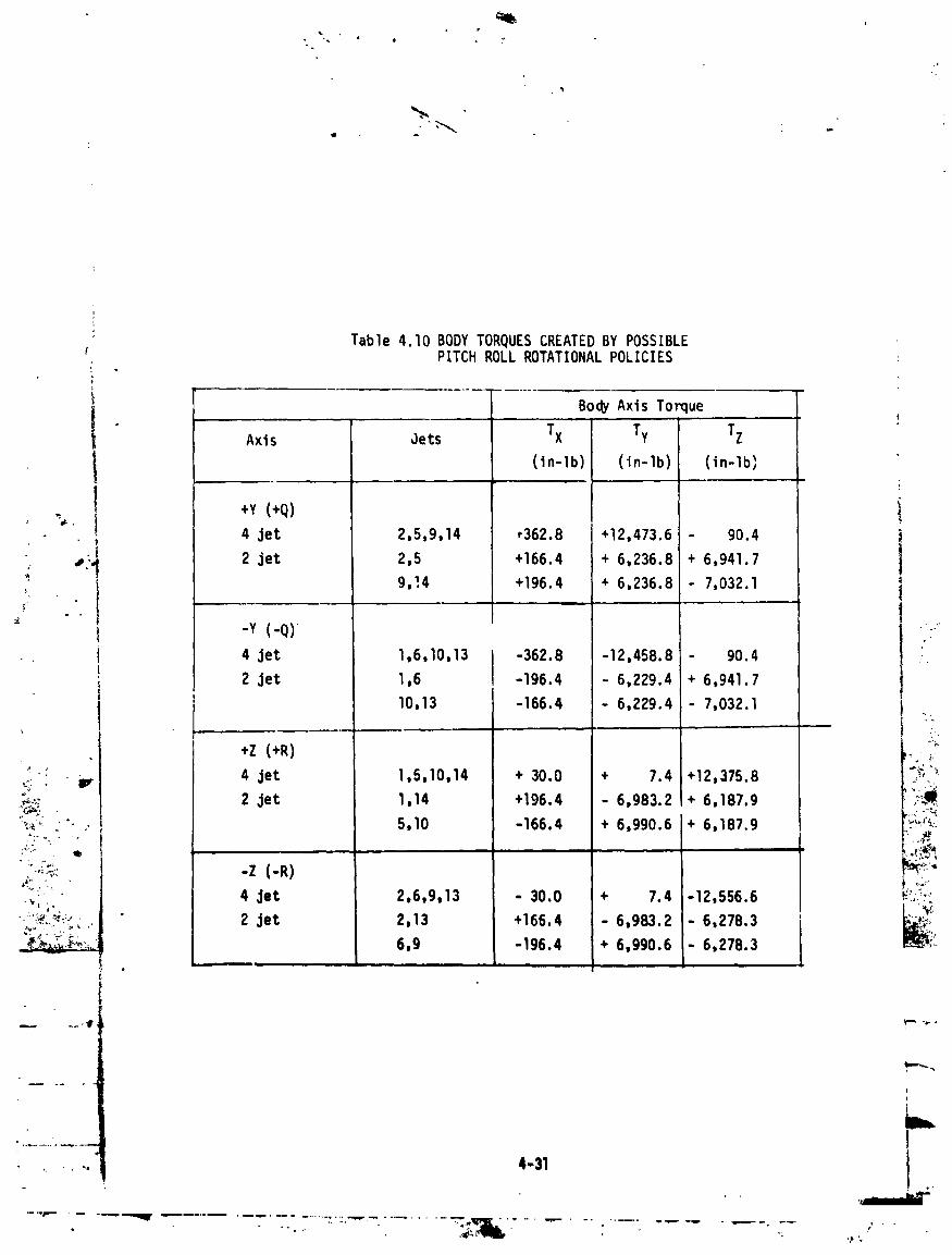
I
: Table 4.10 BODY TORQUES CREATEDBY POSSIBLE :PITCH ROLL ROTATIONALPOLICIES "
i Body Axis Ton ue
I Axis Jets Tx Ty Tz
(in-lb) (in-lb) (in-lb)
_ +Y (+q)
4 jet 2,5,9,14 ,362.8 +12,473.6 90.4
s_., 2 jet 2,5 +166.4 + 6,236.8 + 6,941.7
9,!4 +196.4 + 6,236.8 7,032.1" ..- -- .
- .y (-Q) ,.:-
4 jet 1,6,10,13 -362.8 -12,458.8 - 90.4
2 Jet 1,6 -196.4 - 6,229.4 + 6,941.7
I0,13 -166.4 - 6,229.4 - 7,032.1
_ • V 4 jet 1,5,10,14 + 30.0 + 7.4 +12,375.8 ":i':._.-,-- 2 jet 1,14 +196.4 - 6,983.2 + 6,187.9'_-_.i", :':.'" 5,10 -166.4 + 6,990.6 + 6,187.9 :,_'_
• ..:,.;j, "_" -Z (-R)
4 Jet 2,6,9,13 - 30.0 + 7.4 -12,556.6 _:,_:'_,_"_:'"_...... 2 Jet 2,13 +166.4 6,983.2 6,278.3 L,___:_
6,9 -196.4 + 6,990.6 - 6,278.3 "
, , ,, 4-31
]9730]7939-076

TABLE 4.11
Sensor Static Bias Errors
MCC4_' PIC (3/17/70) TEl (4/14/70) (4/15/70)
i Gyro Static X O.06°/hr *(-0.II to -O.19)°/hr -O.12°/hrBias Errors y _0.30O/hr .0.34O/hr .0.23O/hr
i Z -0.47°/hr -0.52°/hr -0.61_/hrF
! Accelerometer X 60.0 _g 5.0 ,pg -16.8 ug{ Static Bias Y -31.0 _g -59.0 ug -59.4 ugi Errors: Z 47.0 -g 57.0 ,pg 47.0 ug i
Reasonableranae derived from noisy data
t
i1 TABLE 4.12i
i Sensor Static Bias Stability .Shift from PIC Exoected Shift from TEl Excect_d•: W_. to TEl (30 days) Ic to MCC 4 (I day) l-
_.t"t W Ik0 . • _ .;_T, Gyros X (-0.17to -0.25) °/hr 0.2B°/hr (-O.Ol to 0.07) /nr O..c','nr
,,-_.. y - O.04°/hr 0.23°/hr O.ll°/hr 0.22_/hr
"_ * Z O.05_ihr 0 28°/hr O.09°/hr 0 2?;.'hr
o_,,,;,- Acceler- X -65.0 ug 77 ug -II.8 ug 30 ,g I_',-
"_:_ Y -28.0 ;,g 77 ug - 0.4 _g 30 ,,.g
Z 10.0 _..g 77 ug -10.0 _g 30.3 it
,It
Range determinedfrom noisy data.
m._
i
1973017939-077
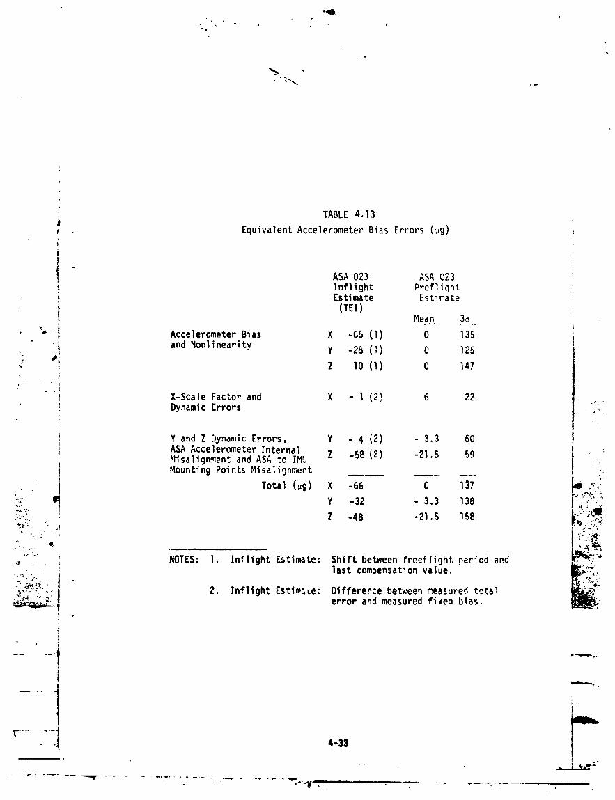
• i
i TABLE 4.13
Equivalent Accelerometer Bias Errors (pg)
ASA 023 ASA 023Inflight PreflightEstimate Estimate
i (TEl) Me___E _____ i-_ "_ I Accelerometer Bias X -65 (1) 0 135
-_ and Nonlinearity Y -28 (1) 0 125
Z lO (I) 0 147!
X-Scale Factor and X - I (2) 6 22
DynamicErrors ,•:;,"
Y and Z DynamicErrors, Y - 4 (2) - 3.3 60
ASAAccelerometerInternal Z -58 (2) -21.5 59Nisalign._entand ASA _o IHU _.:
Mounting Points Misalionr,,ent __ ;,
Total(pg) X -66 6 137 Q -,'_-v
,:,;-- i Y -32 - 3.3 138 _
:-_'- Z -48 -21.5 158 L->_;_:
'_"_ NOTES: 1. InfIight Estimate: Shift between freefIight period and ._,,::'"
last compensation value .L?'.:_..
._.,,-,... 2. Inflight Estimate: Difference betv.eenmeasured total
error and measured fixeo bias, -
4-33
.. _°.._..: ,, , .... _ .... _. _.... ...
1973017939-078

TABLE 4.14
Equivalent Gyro Bias Errors (deg/hr)F
ASA 0?3 ASA 023Inflight PreflightEstimate Estimate ',(TEl)
Mean 3o
Gyro Fixed Drift X (-.17 to -0.25) (I) 0 0.59
y -0.04 (!) 0 0.66 i_ Z -0.05 (l) 0 0.67 )
X-Gyro Dynamic ii I-Oil4 0.35 j
,," Drift (0.0 to 0.08)* (2)
X-Gyro Spin Axis ,_ 0.07Mass Unbalance
Y and Z Gyro Dynamic Y 0.04 (2) -0.08 0.34
Drift Z -0,15 (2) -0.09 0.30
Total (deg/hr) X -0.17 -0.14 0.69
Y 0.0 -0.08 " 0.73
Z -0.20 -0.09 0.73 ,ira,_
_;'_,., NOTES: I. Inflight Estimate: Shift from last freeflight period and I_._,, ,?_i' last compensationvalue. II . :',:
-h_L Z. InflightEstimate: Differencebetween measured total J" ,.Z
_:_T';:_ error and measured fixed bias. _' ;"
* Possible range derived from noisy data.
4-34 II_
...... . . _,_.,_,:
" ........--" ..............-;-'_L..........................i
1973017939-079
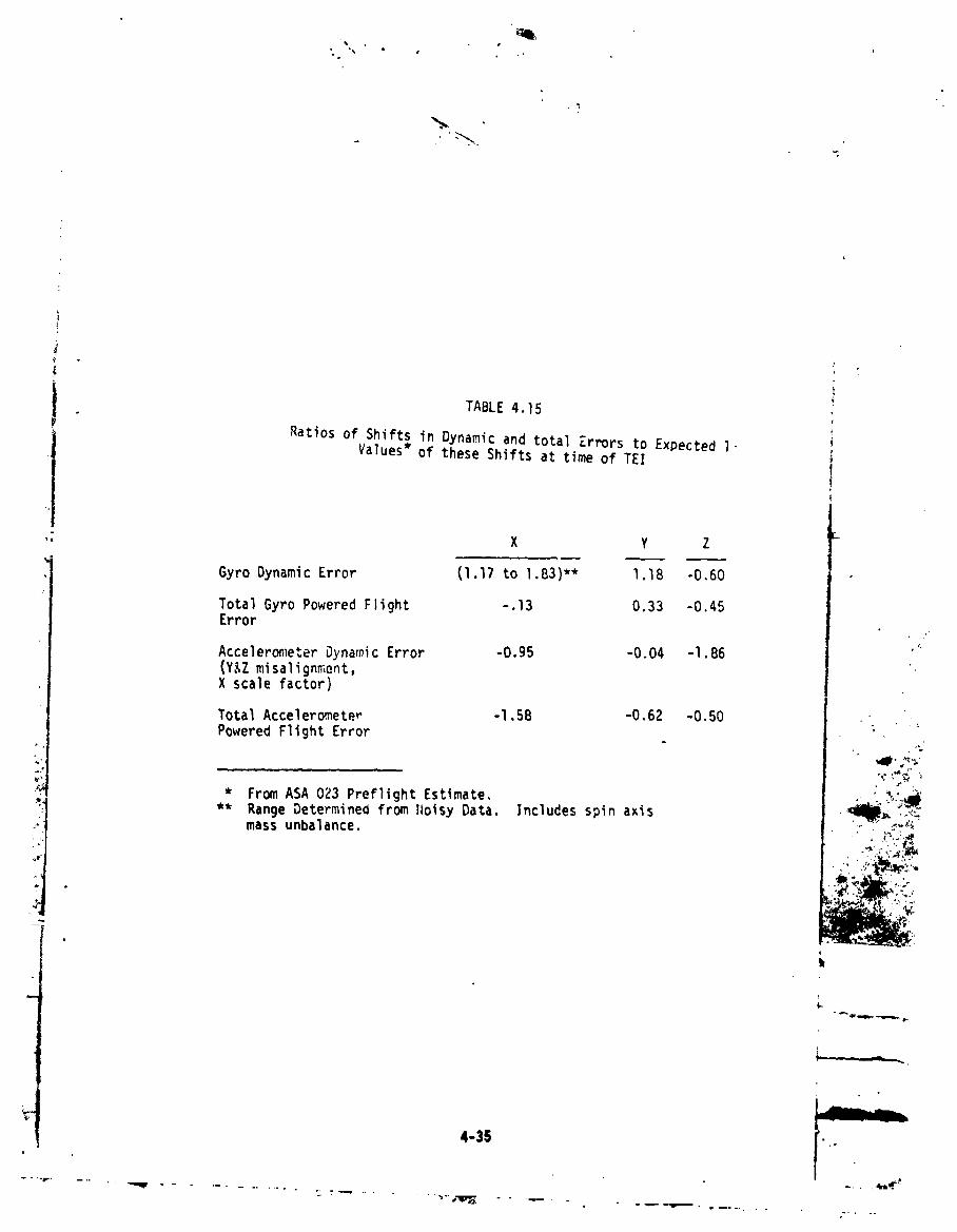
TABLE4.15
Ratiosof Shiftsin DynamicandtotalZrr_rsto ExpectedI.Values*of theseShiftsat timeof TEl
" X Y Z
GyroDynamicError (l.17to 1.83)** 1.18 -0.60
TotalGyroPoweredFlight -.13 0.33 -0.45Error
AccelerometerDynamicError -0.95 -0.04 -l.B6 '"(Y&Z misalignment,X scalefactor)
TotalAccelerometer -l.5B -0.62 -0.50PoweredFlightError _
,IPy_-
* From ASA 023 PreflightEstimate, , .:_m_
** RangeDetermineOfromI¢oisyData. Includesspinaxis ._._ .._.massunbalance. - :_,_
•_ ¢'( _ '.,
t
)
4-35
. ... ,,r mn
i i
• _.;_ .... __
1973017939-080

....... , .... ..: _"_ •
.....F''i_]!,::_-.,i_i-!--_.-.'.._-_;_i_'.i]_.d
.... l..::.-"_ S',.L'::SZ"I:"Wm_'m ,_
.....,..:-.... :i.-,....; _-
I.: ".{.'.i"IT:. .., ".....:.{1".1...4_ i Em=t,--
..... _.--..--........... : :-.:¢--.i.... ., ,,......
•:!.{: "-'.i:. "..i i _,,,I i ":' -.4 ...... :: .-::. '----_-:-'...._:-_l'::-:---... _,""._'i.i!:!: .... ::..i'"":':...""{ m_
.............. :!'" i......... _.-, i. i -i.--+-'_"_-'':.• l :.:'.l • J:..I
• i :'.i .. : _ : " '...... •'_:i .... L.I ! " .._
•;"":""._"' ...... ":'_'_': : " "i .i......-.---_...t-"" ',,•i .........
; . : i : i _ i..i :, L.._..._-..-.".-I:-::...... !....l.i" ..} i.....".....},---_....i.-_-.} • ! _ •'_
• .. • ..... , ! { •
_::.•l--i...-...• . .
" i......." """i....," l.i _ .+......-.i........! : ...i:...L...'-_..' :
". :: ; ; ' ' ".'1""'_'1" :_...}.. l " _ ' '• , : ; : :
i ; • ; . !
.- " .... i -.-!-i:-4:--.-".._--:-. i ...... { _ "I"
_'" ; ..... !_ -_ i _
,...... '. -.-I-.....i"..{ • •
i . ; . : {'"i" " _''_ ..... ;''.: . • ,L. '"
,.. .............. i...._....-.,...{I -t
• " . : i • . ,, L_;o ; .... i .
".;;. " : : : : : ."! _...
IP" "
""_-::t"-_'."f'"_"' "! "
t
• H: ': ..._ ." £....... : : !:!.:..
.... ...- .......... . ........ _ -- . _- _;,,.. -- • ......
1973017939-081

0
P
N
N
, %
..................... _='_
° 1 i
1973017939-082
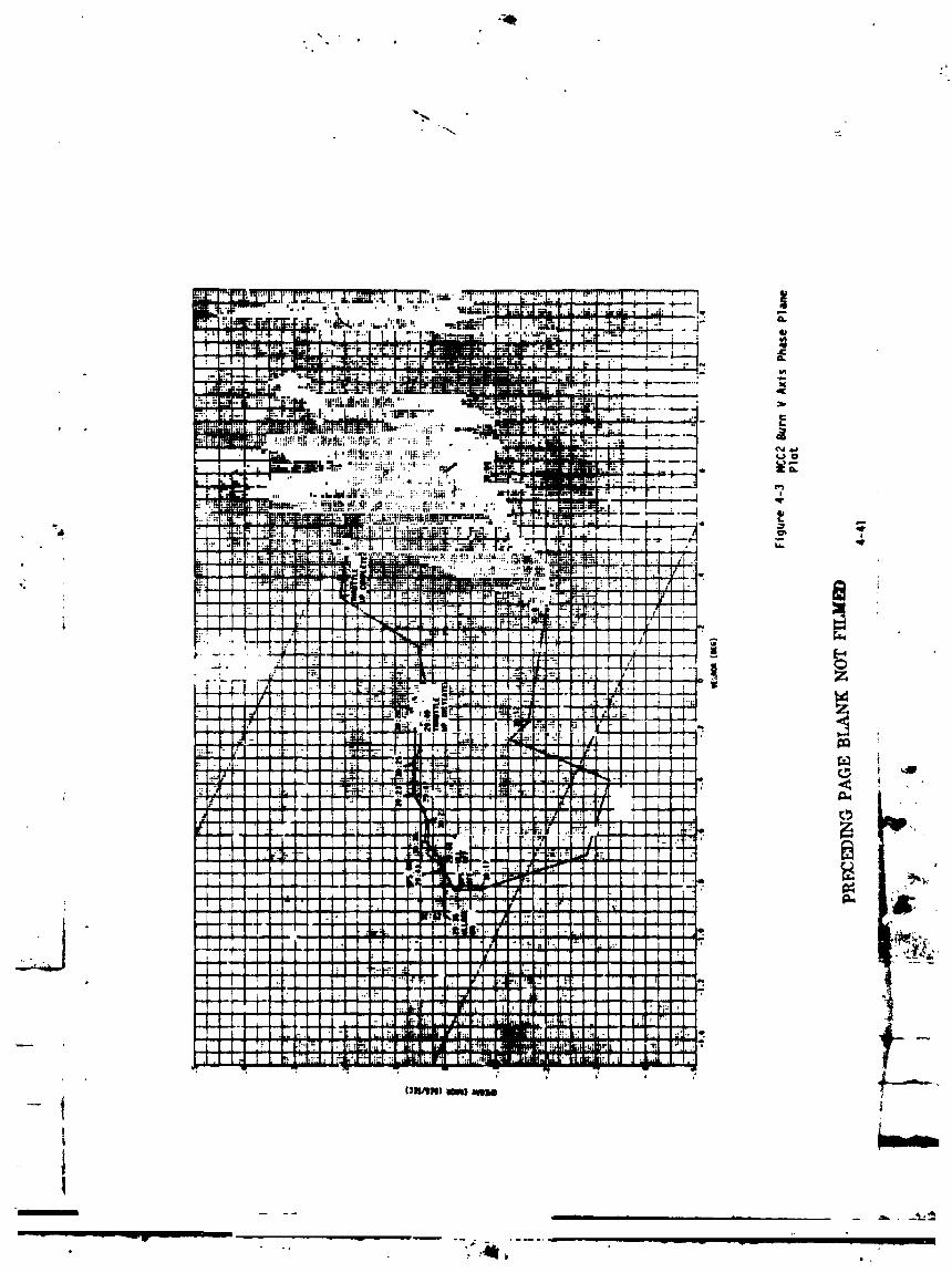

-o
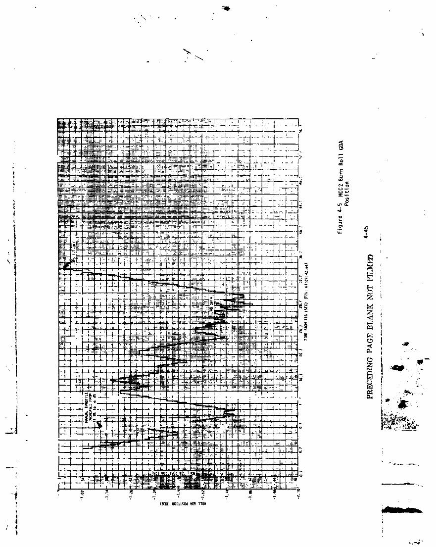
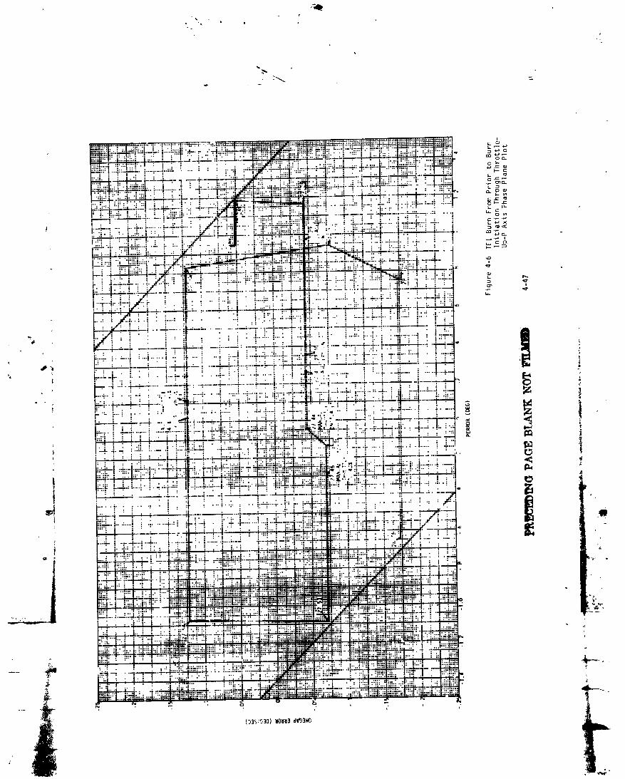


1973017939-089


ql
1973017939-091
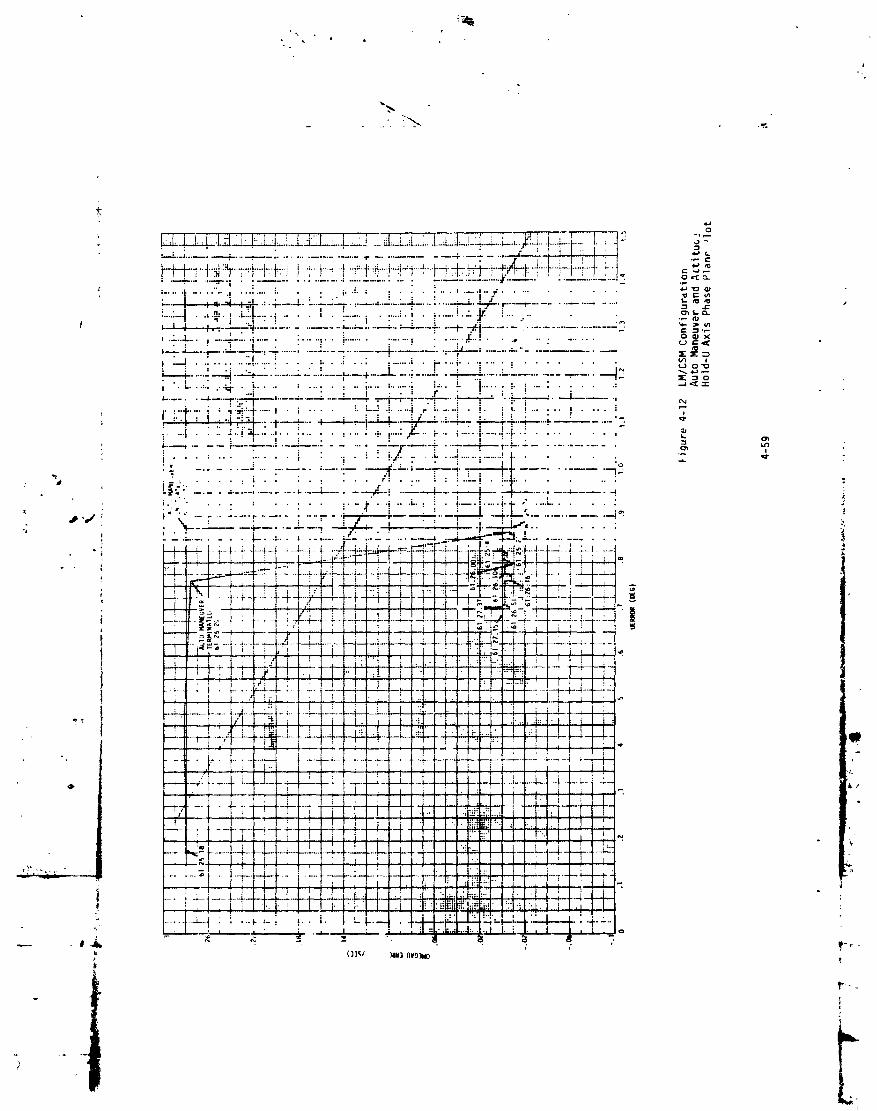
./

1973017939-093

Iiii,.
1973017939-094
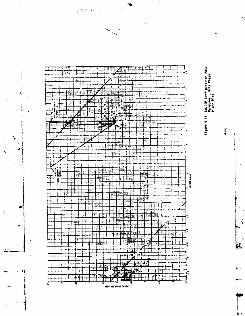
1973017939-095

o.
] 9730] 7939-096

1973017939-097

II
! '-"I"_'I_,: "-" "'1...."'I. " ;;'.'I"....I"""_;_,-.'I..,._'::i:_..'.'.'.'.'.'.'.'.'.i=-.i::.L .l;'-:-..l-"-,':=:l-"- ;r'_.il'_'i_T'_
_.i-=_ !...--.-i......J,:,+...,---# .... .I-..... !-.._._. _i.-.....:... I-.-..i,,=-4-"'"T':-" 4 ...... - ..... ".... l I i : • • " "" : • : '."'.i :1::: .-._! " : :T__'_..._.;:.j..:.:___" " _ " : '_' ... ,r_-,-._---_-.-4...... " ..--_- , " " _ ,, ...._ .... -_ -
• ; .__..,,' • : i "'i .:" :...!.:. ". i i • • "' : ,.,.I . i-....,-.....4..-__..,,-.-_-'--=--.--.._w..._--..---..._::'_.......,.......-......,-,'..-_.._"._: : i= t#1•1--"_ i i • . "if. i" -% .' ":'. • : _ . ". : I ; l . •• -.-,--.,....' ,4..._ 4.......,,...,.........,......_...-..,,.--_....--.-4 ..o--,<
• , . . . , • i .... , • I• ; . : • ;. : " " ..i • "" "
--- 4......... , ." "...... t "_",-_'1-" I _--i-" • I • . • . '' . ......... ". I- .... _ _• • • . . . . ._ " "." .I 1 _ ....• • " i . | ......... • " " ,_,.---+....... _ ..... _-i-x--,L:-]-l...-..-".-_.-:....x---4-..--.,,_ ...... ..--._ ........... '- °
• , • i • , ....._ ,,,-,;,._ ............ _" ..-.,-.- ......._ - _,-,!,'_, .., •• • ' !:.'-i-"i--..-_p-L.,-_-._: h�¬�8�,--:",,..-.-...'......i.-_-.......'--, ....• " , .. ' • ., .% • .:-:. |" ,, i • , _ • • .JL I : _" . q" Q...+................ .-.......... ....._...... ,=o• • ", : I • • ,,,.... "_::.._ .... .. • ; I . . • • : ,2: : ...... I 0 1to, ...... i ...... ._."." .... "i.... - ,,'!'" :.'"i'"" +........ i _ _
• ; • • _ :.....:: _..: . • - . . . ej : . " : i:=' _ Q,.r-.---t---n ---"r-.--.,-" ':..'_.'.: ",_,--l. ' Ii "_,'-r ........ : --,-'--;; +---,i-...--I ..: ...iii ..... ;.,._.'..+,rl,-.,.,.,.,._'._.'_._ 4 .+-..: i...';---t.......+-""'i.. 4..... i.... , :. i _++, o,I_..'...L.L:- -.,.-:--i--._T..'..l-_-i'..-tAL" o-_,_-j_._L_..,li ! _ ":..:....l-..---;----Ji--.2 _"?' _I." I / • "1 ; I ' ": .... _ _......... ; . • .'K ...: i . i . ",l" ,i.,l l'-• , . : .. ,: .. : ..,, • |. : . .... ..::.... _-::: ;.., .: ,_ ....... . : ,
.....t " ....._ +' .................."_ .... _:_-:':-:l: ...."" . • .. -- .................. . .... _ L.. ; .... I ...............,......-.... ....... ._ .............. _. . . _-..... _ .• • , I .... • .,':'.':"_ .......... .,, • i "" ::: "" " ! • - I " " 'LI • , • _-.:'l -r -,_,., :T::_i • • • =oI -.-- i - l .... i" ..... .'l'='."",,,.-_.,b': i----'--e. ".:-:'i_'."l-{,'_--4""r- ;' "i,':' -." : t!:'-':'..i-:4"':_ .... ' ....4" • :.'"-"LI 4I ; • '. I : : ": *_ : " | • : i . : • : . 4- ," I. . , : ; • "_1 :.'. • : :
..... : : • • . : • ...... ..: ...... ...... . • _.._--+--_,.,-._-* , I "1 __.4_;.]. _ ...... .J
I:":--.)...... . i .,.4...........+...... : .I..-'4........._.'.--• ."_-'P/..:.--+, , ...... ; .....4 ,._"i@. ;.-.4........i.--...4-., . :..-"--4.:....i-_..'-_., . , :. _-i---.:,..-_--.. . ...... _.-t _o r- .,t' : " " :" ..... .'...... t .....," " "+ ..... "+"..... ""': • i_i;'!..4:.......... :.......... : I _ '_ ":
• • : ' • • i . • . . , t.I---.,- ...... r- ..... "..-.'. ..... t-- ."f_."_ r-T-.. "-+",". ". "r _ ,---.--] ._
.. . • .: • , . . . : I I _ t,+%,+_
I-".."_" .... i': ' ".'"'!"'r ""i" ,!_i.""':!"r":l..-'+.,,"".......:'" "-" """ : " " :" i...................... 4-" _---i-... , • :. • :..L--.L...-4-.-4_ ...... -_.... !......4"i .. +.. ;.. i.-.. I. i...-..t.....' :-;----t ...... + .... i + ........ i;- • _........- ...... +-.-L--I-,-+... --i--.-.i..--..-.F........ ,,:----4-:-7.....I "" : :_ i, . ..... . .• , . i . : ..... ; .... I.. : -. i ...............
: : • . .• ._. ........ _ ..... • _-- .....i .......... ___.i ..... - ......_ ...... i_ i
-. ; .... -"-- • ; .i-- I i : : I ' : i ' • " i.-..,------_---" _t• " : -n --.,-i.::J--.-v:..:i_-'---.:.'-:-'+.'.' ' ' " ' ; li
_--.::-i :7.--+-:-.,."--_-_-`'-'--_-_'_-._......... -,..,. : .. '=7:............"-7:' ......'....-'----......:-',?!.TT:;:-:-?..---..-..-!: :" i - i .-.i .... i .
.... 4::ii:i ':_..-:- :.T_ + ,_. .....T.. _.... ".i.---,+- _-= .... ;--.' .-+-...;-..+__: ---;..--V-k--i---_ .-_.-P--_-.-!--..-,-.:--_-.'-----_:• • ' : : . . . • . i . • . • : .";-.. , .... . - - t-..! • . • I ..... Jr... :-;._---.--I..-.---i-,-.1-.-- _ • ..,. • ,_ ....L.._ ..... L_.-._.; '..i -i -: .-_.i---2--1:-L¢.-I ! i : !. : ! __P.: . • . I I I : . I • I :" "l ; I • : '. : " : _l_• : : .... : • • i "l : i..... :. :.-! • :....... t.--:-,.i. :"-!---i'-'=-: ! . .L...... :
................., _ 4--"-1 _ r i '" " ": ' ! ' ; ":". [':_! • :........ • -._....I i..:.4......I. •..'.--_.-!-.!-;-.4._4-!.._-.
-............ { , _ .--4--4-----.4---..----I--_4.. :! _: #': -- "lllil'_,,
i ; i._. !-! _-:•_.-.1--- :.-F-i_._"+-4: _'_-__ " '................. -' • - _ •I '.if---'--.'--T--I-._ _ , i , ',....... _ - • " ::-:l ......_ :_"::. !.....i......-'1"_i..- '•r-:-..::-: : '::":--.-!:i ::7::,:t_.-..i_-;:' ' : '"_+'
i-.: i--, ...'.....i! ,-..!_..• : : : . I , • _. • .: !
.........."i ...... :............ -I-_--f.,-!.:i_-_: ,. ....• .+. _ ; i---,_---i---.+-i.-i.--t.i--i:-.-!.--7-]---4...-4--, .-.,.,+_ •4, • -" ' ,' ----I i ; i ' i ' " - "-t--• . • = I : • i / ; / : I"i " ." i i I'- ......... ',........ ; - l " 't--:"-'l"";:':'l" " I 4+'"!- -;"+I.------+-..... ;- ; ..4-.......... _ ----
• • ;.." ./ , / i • . : _14---- • _ i I |" I" I : I • '....... __ " ,'--'"-r-_-----'_-- , ".: . , "7 • ! ' ' I ' ..'• i ' " " .i l.;.._ • , ' • ',:_ , : i ..... : + I I I i, 'i I ! 1 ! i ;I i'l 'IL'. :i::i!l:"l;. ::t ;::'1:'1 '1 ' [i : I . • . " ' : : .; ' -I | I __ __" _ _ - :'-! i. I-"!. !:: !',' ;.:!;', ,_.i, , _._-.._...--+-.,-'n---_ +,=• _ -- . I ,4. • . I... _ ..... -._=_ .................. i - t.... I...... •-4"-'- "; • "_..__ .-'_F'_F'P'I-i 2 , - ; i ; : " ; I i I'.! i _,:::1=-,: :;-I i i . I • , ! "_, ......; - ." , I : ; : III : I • ..' '_' ' , • • : • "_I--+_--.: _ _ r._l=.+.-._.4 4 4. .I=._. I.._,_:+, _ ...... I., , :-..i--..:. ._I I .I. ...
' -" _ ,' " T" " _ l--" ,--
1973017939-098

i
,/ i+
1973017939-099

,+

"w.
10
,i
t
r""-
1973017939-101
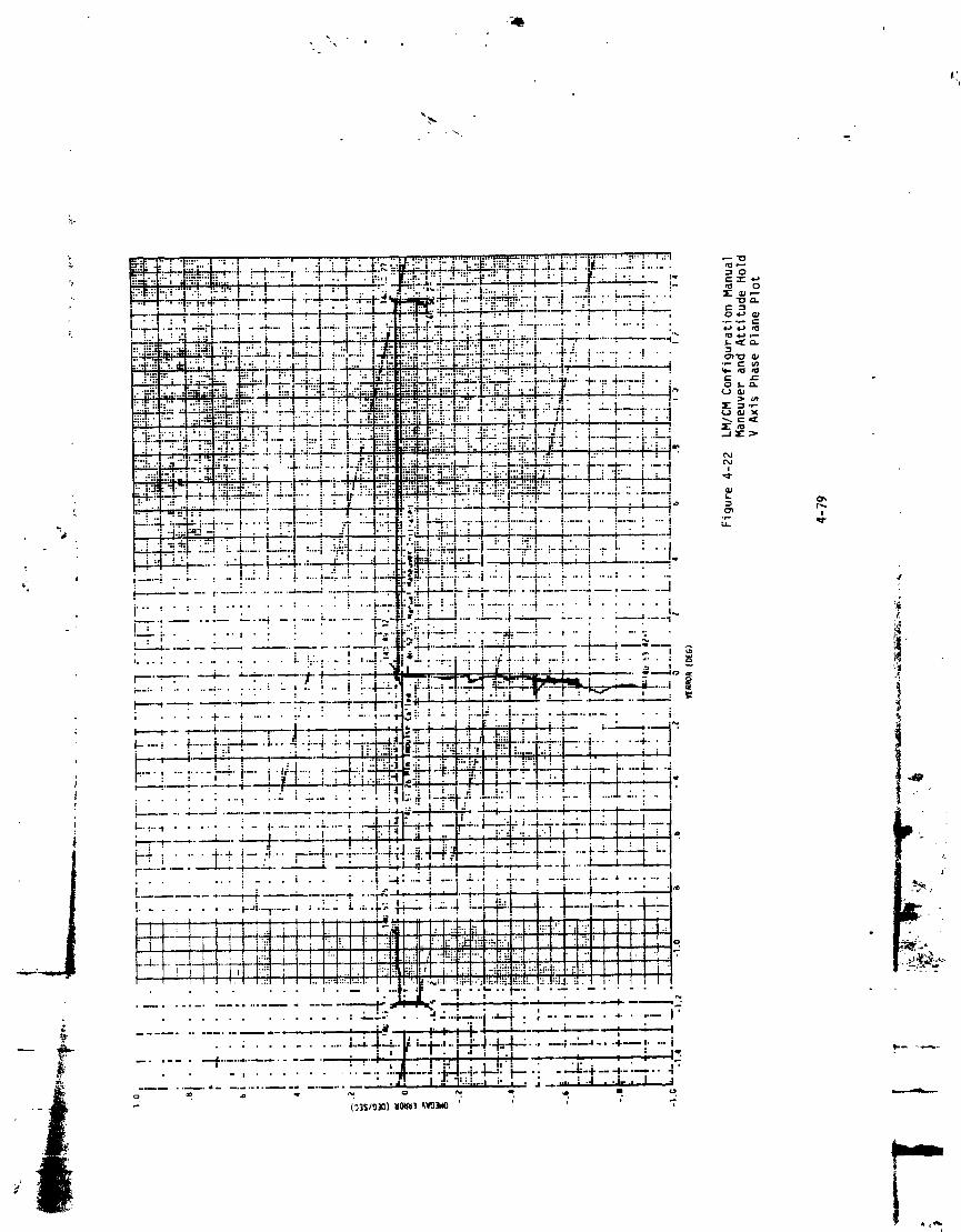
1973017939-102


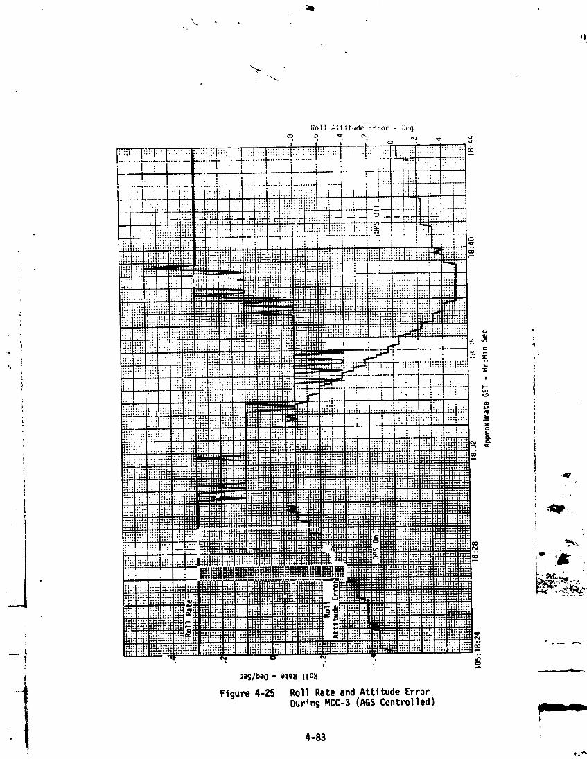

i,• i

_p _.
N o N ,.
Figure 4-27 Yaw Rate and Attitude Error
i During HCC-3 (AGSControlled)
'I 4-85
1973017939-107


-LW
Ftgure 4-29 Acquisition of YawAttttude for MCC-4Burn
4-87
1973017939-109

"--.,..
Ftgure 4-30 Acqu4s4ttonof Pitch- Attttude for NCC-4Burn
4-e8
1973017939-110

Figure 4-31 Acquisition of Roll
Attitude for _C-4 Burn
" 4-e9 !
1973017939-111

• , . ..
I cp
g
Figure 4-32 Spacecraft Attitude DuringMCC-4 Burn (AGS Euler Angles)
i
4-90
t,
1973017.(::).3.q-1lP

................... I I
off
,i,u
i wu
iLd
" i,- !,inw
° i,il
=b .bq,! !_'< 1
i ,4',,
, it I "_ • q
I_ t '. 79:27:15 28:05 28:55 29:45 30:35 31:25 32:15 • _,_.
TIME GET (HR:MIN:SEC)
FIGURE4-33 ACCUMULATEDX-AXIS SENSEDVELOCITY _ .....
"_ 4-91
1973017939-113
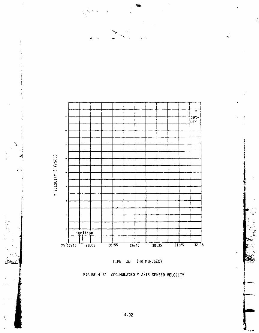
4 '
, *- ignition l
- I_ i I79:'27:15 28:05 28:5! 29:45 30:35 31:25 32:15
-'_ %:
TIME GET (HR:MIN:SEC)
FIGURE4-34 t.CCUMULATEDY-AXISSENSEDVELOCITY
4-92
1973017939-114

-.
i,
, , . C.If_ -
off .I '{ ;
t
•i t • '"
- _
mi I.. ....
t2i
>.p-
_.1
°..
- I
2];.4.
w -- i::tgnt tton -- .__,_
N
o ,:,i:i:_ 79:27:15 28:05 28:$5 29:45 30:35 31:25 32:15" v
TIME GET (HR:MIN:SEC)
__ FIGURE4-35 ACCURULATEDZ-AXiS SENSEDVELOC[TY _.
4-93 l
1973017939-115
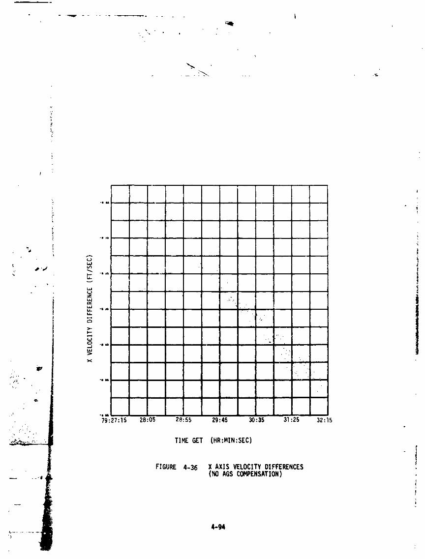
4-g4
1973017939-116

• e mGJ * .. •
J,iJ -t qltll i i
t_ n n
wZ e odl6
I.I.LL I n
_ '.
I'-
0_j Jul
} "O 11118 II
. _
• _ :il
•o.- _!',. •
•o ,o, --
79:27: lS 28:05 28:55 29:4S 30:35 31:25 32:15 L_;' ,;;:
TIME GET (HR:MIN:SEC)
FIGURE4-37 Y AXIS VELOCITYDIFFERENCES(NO AGSCOMPENSATION)
4-95
1973017939-117

• , °
il
. . ,..,i _nn
-_ ,1111
L
_" "'79_27:!5 28:05 28:55 29:45 30:35 ,:25 32:15
TIMEGET (HR:MIN:SED)
FIGURE4-38 Z AXISVELOCITYDIFFERENCES(NOAGS COMPENS#.TION)
1973017939-118

L
i II II II I II I mli ill, , i .,-"i i
• , o
Q $ ,,
hi ..
W
Z : it. q
¢.)
,-,I
X
i
TTHE GET (HR:HIN:SEC) _=i_ _-
FIGURE 4-39 X AXIS VELOCITY DIFFERENCES (COHPENSA_n FOR iAGSACCELEROMETERERRORS) " "_:'-
4-97
I,_°,
J
1973017939-119

•., _ .......... _ ..... _, . ...... _ ........ _,. .... J , . _ L .
-; "- "I 08
79:27:15 28:05 28:55 29:45 30:35 31:25 ]2:15
,,, TIME GET (HR:MIN:SEC)
_'_'_r_L_ _--4 FIGURE 4-40 Y AXIS VELOCITY DIFFERENCES (COMPENSATEDFOR AGS _CCELERI_IETERERRORS)
4-98
1973017939-120

l " • i
- w . ,.... v _ .....
IP
=., i
L"L,J
• Oe
L.L_
" !
=,J ., ,,! . IL.J IINi
m
1973017939-121

, I I
....... 41.
l
- ,IIGQ
,lle
79:25:35 26:25 27:15 28:55 30:35 32:15Q,
. - TIHE GET (HG:HIN:SEC)
FIGURE4-42 AGS/PGHCSANGULARDRIFT - X BODY
1973017939-122

_41t
il4HI ..
4-101
1973017939-123
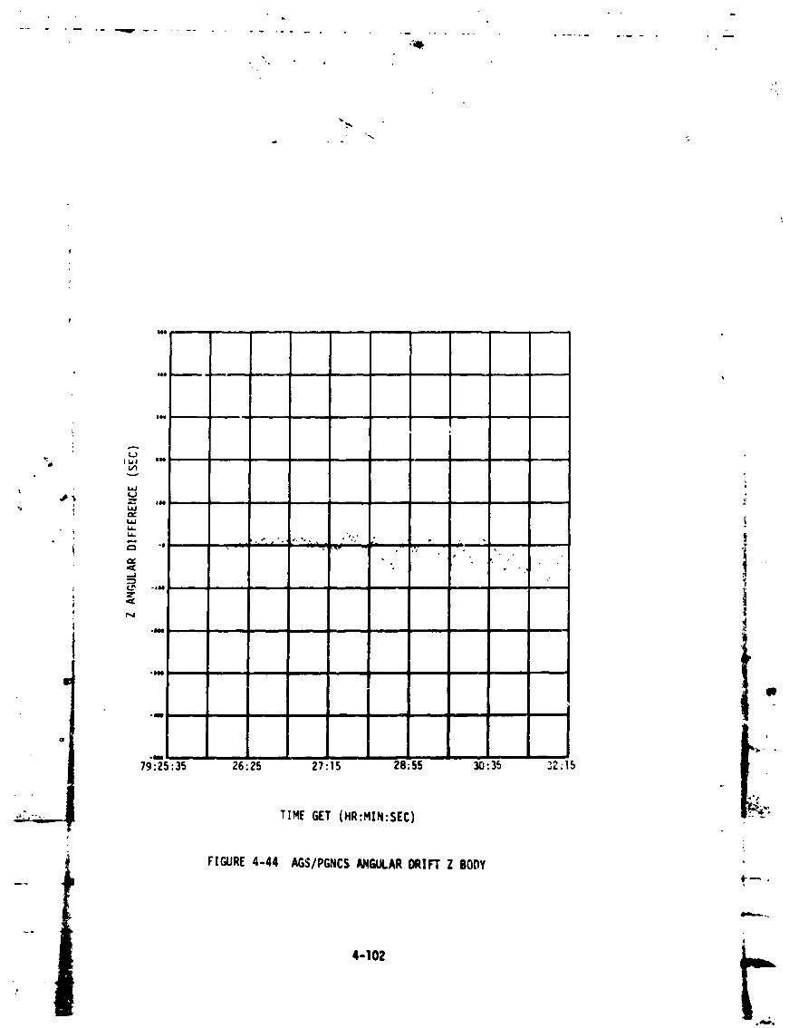
lllll •
,I..J,
":"6 I l_J
l,.+,,J +
,,p_ +_..
? i,
, • . - .
_ °o -o...J
• Olin • _
m "_ t m_
o
79:25:35 26:25 27:15 28;55 30:35 32.15
tt._
TIH[ GET (HR:HIN:SEC) 9-
++
FIGURE4-44 AGS/PGNCSANGULARDRIFTZ BO[1Y +i
dlmh.,... _
4-102
++
1973017939-124
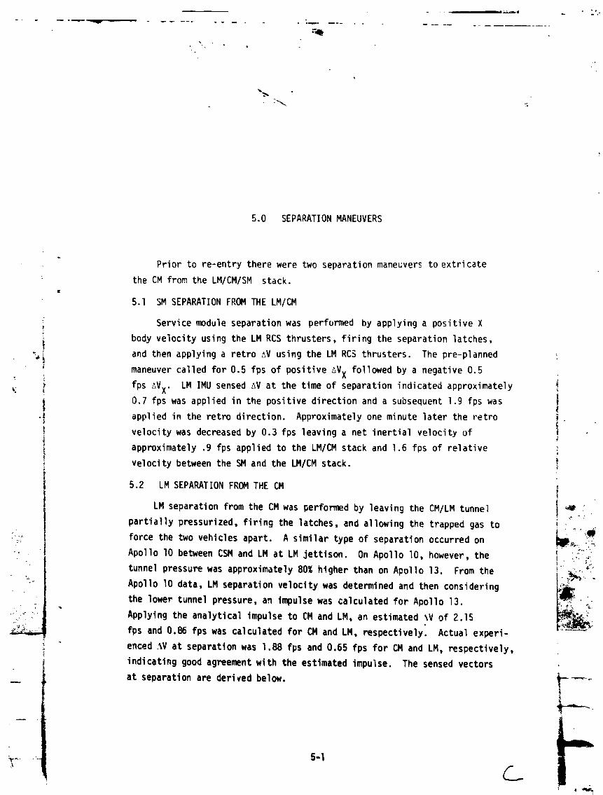
5.0 SEPARATIONMANEUVERS
Prior to re-entrythere were two separationmaneuversto extricate
: the CM from the LM/CM/SM stack.
5.1 SM SEPARATIONFROM THE LM/CM
: Servicemodule separationwas performed by applyinga positiveX!z
i body velocityusing the LM RCS thrusters,firing the separationlatches,_ and then applyinga retro AV using the LM RC$ thrusters. The pre-planned
maneuvercalledfor 0.5 fps of positive_VX followedby a negative0.5
_. ) fps _VX. LM IMU sensed AV at the time of separationindicatedapproximately !
0.7 fps was applied in the positivedirectionand a subsequent1.9 fps was i"I appliedin the retro direction. Approximatelyone minute later the retro _
i velocitywas decreasedby 0.3 fps leavinga net inertialvelocityof
i approximately.9 fps appliedto the LM/CM stack and 1.6 fps of relative
! velocitybetween the SM and the LM/CM stack, i
I 5.2 LM SEPARATIONFROM THE CM ,.
LM separationfrom the CM was performedby leavingthe CMILM tunnel _
I partiallypressurized,firing the latches,and allowingthe trapped gas to i "
:;:' I force the two vehiclesapart. A similar type of separationoccurredon _ill_,:_:_r_:_ _ Apollo I0 betweenCSM and LM at LM jettison. On Apollo I0, however,the _:L>_
i°' _ _tunnelpressurewas approximately80% higher than on Apollo 13. From the _ .....
"-" ApolIo lO data, LM separationvelocitywas determinedand then considering q_/,_ "the lower tunnelpressure,an impulsewas calculatedfor Apollo 13.
;,_ _ Applyingthe analyticalimpulseto CM and LM, an estimated _V of 2.15 _ _""
fps and 0.86 fps was calculatedfor CM and LM, respectively. Actual experi-
enced _iVat separationwas 1.88 fps and 0.65 fps for CM and LM, respectively,
indicatinggood agreementwith the estimatedimpulse. The sensedvectors
at separationare derivedbelow. "_--_|
!_.... 5-I
1973017939-125
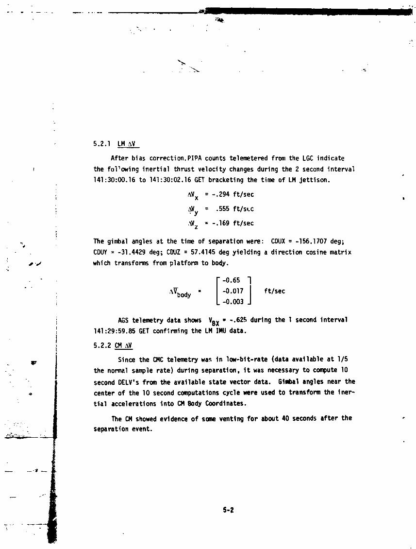
5.2.1 LM _V
After bias correction,PIPA counts telemeteredfrom the LGC indicate
the followinginertialthrust velocitychangesduring the 2 second intervalm
141:30:00.16to 141:30:02.16GET bracketingthe time of LM jettison.
= 294 ft/sec_Vx -.
,: AVy, = .555ft/stc
%Vz = -.169 ft/sec
The gimbal angles at the time of separationwere: CDUX = -156.1707deg;
CDUY = -31.4429deg; CDUZ = 57.4145deg yielding a directioncosine matrix
#,j which transformsfrom platformto body.
• 'iV-hody__ = -0. O17 ft/sec-0.003
AGS telemetrydata shows VBX - -.625 during the l second interval141:29:59.85GET confirmingthe LM IMU data.
5.2.2 CM AV
, m Since the CMC telemetrywa._in low-bit-rate(data availableat I/5
the normal samplerate) during separation, it was necessary to compute lO
second DELV's from the available state vector data. Gtmbal angles near the
center of the 10 second computations cycle were used to transform the iner-
tial accelerationsinto _ Body Coordinates.
The CN showed evidence of some venting for about 40 seconds after the
separation event.
1973017939-126

--- -_ ............. . ............ w ........... q ............
• -. • • .-
_z
From the reconstructedthrust accelerationsit appearsthat the CM
experiencedthe followingvelocitychange across the separationperiod:
j
) , AVx {body)= -1.54 ft/sec
i AVy (body) = 0.42 ft/sec ,AVz (body)= 0.99 ft/sec
} +l
t_. The CM DSKY displayof thrust velocityin body coordinates(VI6 N83)during the LM separationmaneuver differedsignificantlyfrom the derived
values above due to the large Z PIPA bias error that existed. Application
of this Z-PIPAbias error greatly reducesthe discrepancybetween the magni-
tudes of the reconstructedand of the DSKY displayedAV (from4.1g ft/sec
to 1.98 ft/sec). The remaining1.08 ft/secdiscrepancyis unexplained.

f
i,
REFERENCES
I. MSC InternalNote, "Apollo13 Mission Report,"197C,
2 NASA SNA-8-D-027 "CSM/LMSpacecraftOperationalData Book " VolQ ' g •
III( Mass Properties), Revision 2, 20 August 1969.
3. PQ Pantason,Grumman IOC No. LAV-500-B53,"Effectsof RCS JetThruster Plume Reflectors on LM Attitude Control Authority,"17 March 1969,
4. MIT/IL R-567, "Guidance System Operational Plan for Manned LMEarth Orbitaland Lunar MissionsUsing ProgramLuminaryIC(Rev 130)," Section 3 (Digital Autopilot), Revision 3, October1969.
!
1R m _
I
1973017939-128