e-2 pressure compensator control - a novel independent
TRANSCRIPT

Pressure compensator control – a novel independent metering architecture
Dipl.-Ing. Jan Lübbert , Dipl.-Ing. André Sitte, Prof. Dr.-Ing. Jürgen Weber Institut für Fluidtechnik (IFD), Technische Universität Dresden, Helmholtzstrasse 7a, 01069 Dresden, E-mail: [email protected]
Abstract This contribution presents an operating strategy for a novel valve structure for mobile
machines’ working hydraulics which combines the flexibility and energetic benefits of
individual metering with the functionality of common primary pressure compensation
(IPC). The aim is to set up a system that uses a minimal amount of sensors and simple
control algorithms. A control strategy theoretically described in /1/ is modified to
facilitate the practical implementation on a mini excavator implement as a test rig. This
test rig consists only of components that are currently available off-the-shelf to show
that it is possible to develop an individual metering system under these economic
restrictions. The novel is more energy efficient than common flow sharing systems but
provides the same functionality. The control algorithm is experimentally evaluated in
terms of functionality and energy consumption. Simulations show potential for further
improvements.
KEYWORDS: independent metering, mobile working machines, electrohydraulic
systems, control strategy
1. Introduction Manufacturers of mobile machinery as well as suppliers find themselves persistently
confronted with increasing requirements regarding energy efficiency, safety and
operator-comfort. This demands for continuous development of control and system
architectures. Control systems in mobile machinery provide hydraulic power to
numerous parallelly operated actuators. For small and medium sized machines
typically one single pump supplies several actuators. This inherently leads to throttling
losses in the inlet paths of the lower loaded actuators. The mechanical coupling of inlet
and outlet throttling edge causes further avoidable losses. Requirements on
controllability of pulling loads and energy consumption lead to a design conflict
regarding the valve spools. For systems with individual metering of the inlet and outlet
this conflict is avoided. Furthermore individual metering opens up for enhanced
Group E - Mobile Hydraulics | Paper E-2 231

operation modes like high pressure regeneration. This reduces the energy losses at
lower loaded consumers. To increase acceptance in industry the production costs must
be kept low and the control algorithm as simple as possible. Therefore a control
strategy using only one pressure sensor in the common supply pipe and spool stroke
sensors at the IPC is developed and implemented on a test rig that consists only of
commercially available components. Many other approaches to individual metering use
two pressure sensors per cylinder /2–5/, which negatively effects system availability
because the increased risk of failure. The pressure compensator’s operation point
(spool position or pressure drop) gives indication about a consumer’s load situation
using just one sensor /1; 6/. In this paper measurement of the IPC position is favoured.
The used valve structure is the outcome of preliminary works at the IFD and will be
briefly described in section 2. A basic control strategy, that mirrors the IPC’s function
with the meter out throttle edge, has also been developed at the IFD. Theoretical
investigations of the valve system’s behaviour in section 3 show that this strategy
needs to be modified to facilitate the practical implementation. A control algorithm is
derived from the modified strategy and implemented on an ECU. In section 4
functionality and energy consumption are evaluated in simulation and experiment on a
mini excavator implement test rig.
2. Design of hydraulic system and test rig setup The valve structure shown in Figure 1 is used to actuate the boom and stick cylinder of
an excavator implement. Individual metering systems are multiple input-multiple output
systems (MIMO). Usually these require complex multi-variable control strategies.
Previous research at the IFD has shown that an individual pressure compensator (IPC)
in the inlet flow path is advantageous to decouple piston load force and velocity. This
enables single-variable control approaches /1; 7/.
The resulting valve arrangement consists of two proportional 2/2 way valves for
throttling and four 2/2 way switching valves to set the flow paths. The individual
pressure compensator and the throttling valves are equipped with displacement
encoders. The structure depicted in Figure 1 allows individual throttling of both cylinder
chambers and their connection either to high or to low pressure. The IPC always
throttles the flow from the pump in order to regulate the flow through the inlet throttle
edge into the inlet cylinder chamber. An ECU commonly used in mobile applications
actuates the electrohydraulic components. The measurement signals are delivered to
the ECU and captured by a data acquisition system. The user operates the excavator
implement with two joysticks transmitting their data to the ECU via CAN.
232 10th International Fluid Power Conference | Dresden 2016

Figure 1: hydraulic circuit for one consumer
3. Theoretical analysis and control strategy The first part of this section is dedicated to a theoretical analysis of the proposed valve
arrangement’s static behaviour. Afterwards the control strategy given in /1/ will be
briefly explained and refined based on the system analysis given before. This leads to
the development and implementation of the control algorithm.
3.1. Static behaviour of independent metering circuit with primary pressure compensator
The static behaviour of the controlled system - a double acting differential cylinder
actuated with individual throttling edges and a primary IPC in the inlet path - is
theoretically investigated. For this analysis the circuit can be simplified according to Figure 2.
Figure 2: Simplified hydraulic circuit
1 - 2 proportional valves
3 - 7 switching valves
8 pressure compensator 10 Elec. Control Unit
9 var. displacement pump 11 Elec. Input Device
y y
y
1 2
3 54 6
8
9
7
13
5
8
24
10[y1,y2,y8]
[IVW1-7,I9]
11
Valve arrangement
Excavator test rig
y
Group E - Mobile Hydraulics | Paper E-2 233
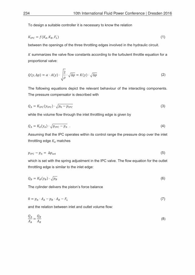
To design a suitable controller it is necessary to know the relation
(1)
between the openings of the three throttling edges involved in the hydraulic circuit.
summarizes the valve flow constants according to the turbulent throttle equation for a
proportional valve:
(2)
The following equations depict the relevant behaviour of the interacting components.
The pressure compensator is described with
(3)
while the volume flow through the inlet throttling edge is given by
. (4)
Assuming that the IPC operates within its control range the pressure drop over the inlet
throttling edge matches
(5)
which is set with the spring adjustment in the IPC valve. The flow equation for the outlet
throttling edge is similar to the inlet edge:
(6)
The cylinder delivers the piston’s force balance
(7)
and the relation between inlet and outlet volume flow:
(8)
234 10th International Fluid Power Conference | Dresden 2016

Putting equations (3) to (8) together results in:
(9)
3.2. Basic control strategy and refinement This section is started with the description of a basic control strategy that was
theoretically developed at the IFD in previous research. Obstacles to a practical
implementation of this strategy will be pointed out and circumvented with the help of a
refinement.
Basic strategy. The basic idea of the approach described in /1/ is to set the
consumers velocity with the inlet throttling edge in an open-loop manner while
controlling the outlet edge in a closed loop in such a way that the IPC is nearly fully
open regardless of velocity and load force, thus shifting the inlet pressures of all
consumers to the same level. This simple concept has numerous benefits:
The strategy uses the IPC as a sensor for detecting the load situation and does
not need any pressure sensors.
With the IPC almost completely open the inlet chamber pressure is almost as
high as the supply pressure regardless of the load situation. With a reasonably
high supply pressure a pulling load can be moved securely at the desired
velocity without causing cavitation in the inlet chamber. Energy inefficient
counterbalance valves are not necessary.
There is no need to detect the load force direction.
System behaviour and obstacles. The diagram at the top of Figure 3 shows the
IPCs opening depending on the outlet throttling edge’s opening for a
movement of the test rig’s boom cylinder at 50 % of maximum speed against different
load forces at a supply pressure level of 100 bar as a specific example, resulting from
equation (9).
Group E - Mobile Hydraulics | Paper E-2 235

Figure 3: Operation ranges for IPC and inlet pressure control
A smaller outlet edge opening leads to a wider IPC opening , since closing the
outlet throttle raises the pressure levels and in the cylinder chambers. This
decreases the pressure difference between inlet pressure and supply pressure ,
causing the IPC to open its throttle further. The relation between and is
extremely nonlinear with the IPC being almost closed over a wide range of the outlet
throttle and opening rapidly in a very small band of (i.e. 0,12-0,13 for =
0), when the pressure in front of the inlet throttle gets close to supply pressure
level . Furthermore the threshold at which the IPC fully opens heavily depends on the
load force . The nonlinear characteristic of varies the controlled system’s
amplification over a large range depending on and . Without
measurement of the load force this amplification is unknown. Therefore its variation
cannot be compensated by adapting the controller gain.
Example: Boom cylinder
y
0 0.1 0.2 0.3 0.4 0.5-40
-20
0
20
40
KB/KB,max
Cavitation pA
margin
Operation range pressure controlInlet pressure pA [bar]
0 0.1 0.2 0.3 0.4 0.5-40
-20
0
20
40
FL [kN]
KB/KB,max
Operation range IPC controlIPC opening KIPC/KIPC,max
0 0.1 0.2 0.3 0.4 0.50
0.5
1
K IPC
/KIP
C,m
ax
KB/KB,max
IPC opening KIPC depending on outlet throttle opening KB
FL [kN]0 15 30 35
236 10th International Fluid Power Conference | Dresden 2016

The left diagram in Figure 3 shows the IPCs opening depending on outlet throttling
edge opening and load force for the described example scenario. The isolines
mark the operation points at which the IPC is fully open and half open. Both
isolines bound the narrow operation range within which the outlet throttle opening
must be set to open the IPC between half and full way (“IPC control”). This requires
throttle valves with high resolution.
This demand and the varying system amplification are obstacles to a practical
implementation of the proposed control strategy.
Refinement of the control strategy. To overcome the revealed problems the range
within which IPC and outlet throttle can be set without compromising the control
strategy’s benefits shall be enlarged to reduce the requirements on the valves’
resolution. Furthermore the controlled system will be linearized to obtain a constant
amplification.
Instead of a specific IPC opening the inlet chamber pressure is now used as
the reference variable for the control circuit which actuates the outlet throttling edge .
The IPC opening is now used to determine the pressure drop over the IPC in order to
calculate the inlet pressure without using an individual pressure sensor at the
consumer. Knowing and allowing values down to a certain margin against cavitation
(i.e. 10 bar, see Figure 3 right diagram) smaller IPC openings are acceptable without
compromising the control strategy’s benefits mentioned before. The operation range
(“pressure control”) of the outlet edge is enlarged considerably compared to IPC control
thus reducing the requirements on controller performance and proportional valves.
The controlled system is linearized by using the chamber pressures as the input and
output variables instead of the valve spool positions (Figure 4). The control circuit
(highlighted) is constructed around the control variable with its reference value
and the outlet chamber pressure as the manipulated variable (back pressure
manipulation, /8/). In steady state these both values have a linear correlation according
to equation (7) with the constant piston area ratio as the controlled system’s
amplification and the load force as the disturbance variable. An ordinary linear PI
controller is sufficient to fulfil this control task.
Group E - Mobile Hydraulics | Paper E-2 237

Figure 4: Linearized drive system and pressure control loop (highlighted)
3.3. Development and implementation of the control algorithm A lumped parameter simulation model was used to develop and test the control
algorithm using the software-in-the-loop method (SIL). The model provides an interface
including all signals of actuators and sensors at the test rig. The control algorithm was
primarily run on a virtual ECU which controlled the simulation model via the Open
Platform Communication System (OPC). Afterwards the algorithm has been verified on
the real test rig.
There are five subtasks the control algorithm has to fulfil in order to move the actuators
boom and stick cylinder energy efficiently at the desired velocities. These are
determination of the current chamber pressures, selection of the optimal operation
mode, calculation of the common desired inlet chamber pressure, setting the valves
and actuating the pump.
The inlet chamber pressure is calculated with the supply pressure and the valve
spool positions of IPC and inlet throttle:
(10)
The current inlet volume flow is obtained from the inlet throttle’s flow map
using the inlet valve opening and the assumed pressure drop over
the inlet throttle edge which is determined by the IPC. With the IPC’s spool position
and the inlet flow the pressure drop is calculated with the IPC’s flow map
, while the supply pressure is measured with one single sensor in
Controller(PI)
Valves and cyl.static behaviour
V/C. dynamicbehaviour
Flow map
Flow map
*
Hardware
Controlled systemwith linear static behaviour
Flow map
*: normal operation mode
238 10th International Fluid Power Conference | Dresden 2016

the common supply line. This method neglects further pressure losses that occur in the
pipe between pump and valve block, the hoses between block and cylinders and
throttling losses in the channels of the blocks and the switching valves. These
simplifications lead to an overestimation of , which will have the largest relative
impact at high velocities and a widely opened IPC.
The outlet pressure is estimated to match with its desired value .
If the condition for high pressure regeneration
(11)
is fulfilled the operation mode is set to high pressure regeneration, otherwise normal
operation. In the former mode the outlet flow from the rod side chamber (R) is
redirected to the piston side chamber (P) between IPC and meter in edge during piston
extension thus reducing the required pump flow.
With both chamber pressures the load force and the least required inlet pressure
to move the load are estimated for each actuator. The highest required pressure is the
common desired inlet pressure for all actuators.
The PI pressure controller sets a desired outlet pressure in accordance to the
control deviation between current inlet pressure and desired pressure . While
the inlet throttle position is set with the required volume flow corresponding to the
desired velocity and the constant pressure drop controlled by the IPC the
outlet throttle position depends on and the desired outlet chamber pressure .
The pump is controlled in an open loop manner utilizing the flow matching algorithm as
described in /9/ and suggested by /1/ to deliver the overall required volume flow. The
proportional valves are actuated by a feed forward signal combined with a PI-based
closed loop spool stroke control.
4. Measurement and simulation results The described valve system and control algorithm are evaluated in terms of the
proposed pressure control, dynamic handling performance and energy consumption at
the mini excavator implement test rig and in simulation. As an example movement the
levelling (Figure 5) has been chosen because it contains all relevant operation points
to demonstrate the system’s functionality. These operation points are resistive and
overrunning loads , both time-varying (Figure 5, centre and right), different required
Group E - Mobile Hydraulics | Paper E-2 239

pressure levels of both consumers and the ability to regenerate at the lower load
consumer.
The levelling movement is driven in manual control with the bucket “in the air”, which
means that the implement is only loaded with inertial and gravitational forces, but not
with digging forces. On a construction site this kind of movement will occur regularly
when the operator transports material from the dug hole to a dump truck.
Figure 5: Operation points during a levelling movement
Pressure control. The measurement results in terms of the proposed pressure
calculation and control are shown in Figure 6. The diagrams display the velocity
commands for boom and stick cylinder, the measured chamber pressures (“meas.”) as
well as the reconstructed pressures (“rec.”, see chapter 3.3) and the relative IPC spool
positions.
Figure 6: Measured pressures and IPC strokes for a levelling movement
The boom cylinder moves a resistive load in normal operation. The inlet chamber is the
rod side (R). The minimal pressure the controller shall maintain in each chamber
levellingt
v
0
stick
boom
extension
retraction
v
FL
High pressureregeneration
boomstick
Thresholddepends on p0
Boom: resistive load, = f( ) >> Stick: overrunning load, = = 10 bar
R
P
PR
2 4 6 8 10 12-0.1
00.10.2
Velocity commands
v [m/s]boom stick
2 4 6 8 10 120
100
200
Pressures boom
p [bar]
t [s]
PmeasPrec
RmeasRrec
2 4 6 8 10 120
100
200
Pressures stick
p [bar]
PmeasPrec
RmeasRrec
2 4 6 8 10 120
0.5
1 Relative IPC strokes
t [s]
boomstick
240 10th International Fluid Power Conference | Dresden 2016

is set to 10 bar. The outlet flow (P) is throttled slightly to obtain this pressure (bright,
brown graphs). This and the load force yield to an inlet pressure of approx. 60 bar
(dark, blue graphs), which is the common desired inlet pressure for both
consumers.
At the same time the stick cylinder lowers an overrunning load in regeneration mode.
The load is balanced by the almost closed outlet throttle (chamber R), which shall also
increase the inlet chamber pressure (P) to the level of the higher load consumer
(boom, 60 bar). This leads to an outlet pressure level at the rod side of approx.
100 bar. The desired inlet pressure has settled at around t = 8 s.
For both cylinders the inlet chamber pressure is slightly underestimated during most of
the time, which was not expected according to the simplifications made in equation
(10). The reason is found in the undersupply condition, characterized by a very wide
IPC opening. In this case the real pressure drop over the inlet throttle is lower than the
estimated value which is subtracted from the measured pump pressure .
The deviations between measured and reconstructed chamber pressures are much
higher at the stick cylinder which experiences the overrunning load. This is caused by
the high sensitivity of the pressure drop of a throttle edge to variations in the spool
position at small openings. Measurement errors in flow map and spool position are
amplified much more than at wider openings, well observable at the stick cylinder’s
inlet pressure (P) at t = 9 s while the IPC is almost closed and its pressure drop
highly overestimated. The pressure deviations in the outlet chamber are due to the high
controller activity which was necessary to raise the inlet pressure to the desired 60 bar.
Since the cylinder drive has a hydraulic capacity the real outlet pressure (Rmeas)
follows the desired value (Rrec) set by the pressure controller with a certain delay
which becomes evident when changes.
Dynamic performance and potential for improvement. The shown levelling
movement is very slow compared to common operation of an excavator at a
construction site. Faster movements at the test rig lead to unstable behavior because
the proportional valves act slower than the operator, due to hysteresis effects and a
slow stroke controller tuning to prevent unacceptable overshoots. For practically
satisfying and safe operation characteristics the valves need to be significantly faster
than the operator. A simulation with fast and precise servo valves, shown in Figure 7,
reveals potential for improvements. The faster valve dynamics allow a more dynamic
pressure controller tuning which shortens the settling time for the inlet chamber
Group E - Mobile Hydraulics | Paper E-2 241

pressure to around 50 % (P, stick, phase between 0,5-2 s, compared to the time
interval between 5-8 s in reality, Figure 6).
Figure 7: Simulated fast levelling with servo valves
Energy consumption. Energetic aspects have also been investigated, Figure 8. The
figure depicts the results for the separate metering strategy without regeneration (SPM)
and with regeneration (SPMR). For reference purposes a conventional coupled
metering strategy (CPM) has also been implemented. In this mode the inlet and outlet
flow cross section area always stay in the same relation as the cylinders piston areas,
analogue to a mechanical coupling of both throttle edges on one single valve spool.
This comparison test has been performed with the simulation model using the desired
velocities from the real levelling experiment depicted in Figure 6, top left.
Figure 8: pump pressure and volume flow for different operation strategies (Sim.)
R
P
PR
0 1 2 3-0.1
00.10.2
Velocity commands
v [m/s]boomstick
0 1 2 30
100
200
Pressures boom
p [bar]
t [s]
PmeasPrec
RmeasRrec
0 1 2 30
100
200
Pressures stick
p [bar]
PmeasPrec
RmeasRrec
Relative IPC strokes
0 1 2 30
0.5
1
t [s]
boomstick
Assumptions for simulated servo valves:Natural frequency f0 = 100Hz, damping ratio D = 0,8, Hysteresis 1%, 1% measurement uncertainty for all valve strokes
2 4 6 8 10 120
100
200
p 0 [bar
]
CPMSPMSPMR
2 4 6 8 10 120
50
Q0 [l
/min
]
t [s]
Q0[l/min]
p0[bar]
t [s] 1 2 30
0.5
x [m]
y [m]
Tool centre point (TCP)
CPM = coupled metering, SPM = separate metering, SPMR = SPM with regeneration
TCP (levelling)x
y
242 10th International Fluid Power Conference | Dresden 2016

The consumed hydraulic power is the product of supply pressure and volume
flow . In comparison to coupled metering (CPM) the separate metering strategy
without regeneration (SPM) shows no energy saving potential in the investigated
scenario, since pressure level and volume flow are roughly the same. For the
stick cylinder as the lower load consumer energy can be saved with regeneration
(SPMR). In this mode the volume flow to the stick cylinder is reduced by 66 %
according to the piston area ratio. This leads to a considerable overall energy saving of
43 % between SPM and SPMR (see Table 1).
Table 1: hydraulic energy consumption for a levelling movement
This comparison has also been performed on the test rig, where the hydraulic energy
consumption can be estimated with the supply pressure and pump angle, neglecting
the volumetric losses of the pump. Since the energy consumption heavily depends on
the operator even the displayed average values only give a rough indication about the
energetic relation between the discussed operation modes. Nevertheless, the tendency
found with the simulations can also be seen at the test rig. The deviations between
simulation and measurement are probably primarily caused by the fine tuning between
pump and consumer at the test rig, which is negatively influenced by the proportional
valves’ slow dynamics. These have not been modelled completely for the simulation.
5. Summary and outlook The developed system, using only one common supply pressure sensor and the
positions of the IPCs and for valve control purposes the proportional valves’ spool
positions, is capable of actuating a mini excavator implement with load compensation
up to certain low dynamics. The high pressure regeneration enables energy savings up
to 48 % in case of a levelling movement without digging forces. More energy saving
potential can be exploited by fine tuning minimal chamber pressure level and pump
actuation, which requires a faster and more precise throttle valve response and
possibly a closed loop pump control.
Currently the desired relation between inlet and outlet flow cross section area is lost
due to insufficient valve dynamics during dynamic movements, which has a great
impact on the consumers’ pressure level. This results in unintended pressure peaks or
CPM [%] SPM [%] SPMR [%] Simulation 100 110 57
Measurement 100 90 45
Group E - Mobile Hydraulics | Paper E-2 243

cavitation. This problem cannot occur with common mechanically coupled metering
where the flow cross section area relation is set by the valve spool geometry. For
independent metering the need for a precise tuning between inlet and outlet throttling
edge leads to much higher requirements on the valves’ controllability compared to
mechanically coupled metering.
Simulation results with metering edges featuring the characteristics of high
performance servo valves show that the dynamic stability and handling characteristics
of the proposed valve structure and control strategy can be improved significantly by
using suitable components. Continuing research will address the handling performance
by refining the control strategy for the used proportional valves. First experiments show
that their dynamic performance greatly improves by applying a suitable dither signal to
overcome the hysteresis. Special attention should be paid to mode switching events
during ongoing movements. Furthermore the strategy will be adapted to altered sensor
setups (i.e. pressure behind IPC instead of IPC spool position) to reduce investment
costs and possibly improve handling performance.
6. Acknowledgements The work in this paper is part of the project „New electrohydraulic control systems with
Independent Metering Edges“ funded by the DFG (German Research Society, GZ: WE
4828/1-2). The permission for publication is gratefully acknowledged.
7. References /1/ Sitte, A. ; Beck, B. ; Weber, J. ; Dresden University of Technology, Institute
of Fluid Power (IFD). Design of independent metering control systems.
Proceedings of the 9th International Conference on Fluid Power. Aachen,
2014
/2/ Liu, S. ; Yao, B. ; School of Mechanical Engineering, Purdue University,
West Lafayette, IN 47907, USA. Energy-Saving Control of Hydraulic
Systems with Novel Programmable Valves. Proceedings of the 4th World
Congress on Intelligent Control and Automation. Shanghai, China, 2002
/3/ Andersen, T. ; Pedersen, H. ; Department of Energy Technology Aalborg
University, Denmark. Investigation and comparison of separate meter in
separate meter out control strategies. Proceedings of the ASME/BATH
2013 Symposium on Fluid Power & Motion Control. Sarasota, Florida, USA,
2013
244 10th International Fluid Power Conference | Dresden 2016

/4/ Nielsen, B.: Controller Development for a Separate Meter-In Separate
Meter-Out Fluid Power Valve for Mobile Applications. University of Aalborg,
Denmark, Institute of Energy Technology. PhD thesis, 2005
/5/ Opdenbosch, P. ; Sadegh, N. ; Book, W. ; Enes, A. Auto-Calibration Based
Control for Independent Metering of Hydraulic Actuators. Proceedings of
the 2011 IEEE International Conference on Robotics and Automation.
Shanghai, China, 2011
/6/ Eriksson, B.: Control Strategy for Energy Efficient Fluid Power Actuators :
Utilizing Individual Metering. University of Linköping, Sweden, Division of
Fluid and Mechanical Engineering Systems. PhD thesis, 2007
/7/ Sitte, A. ; Weber, J. ; Dresden University of Technology, Institute of Fluid
Power (IFD). Structural design of independent metering control systems.
Proceedings of the 13th Scandinavian International Conference on Fluid
Power. Linköping, Sweden, 2013
/8/ Shenouda, A.: Quasi-Static Hydraulic Control Systems and Energy Savings
Potential Using Independent Metering Four-Valve Assembly Configuration.
Georgia Institute of Technology, Atlanta, Georgia, USA, Woodruff School of
Mechanical Engineering. PhD thesis, 2006
/9/ Djurovic, M.: Energiesparende Antriebssysteme für die Arbeitshydraulik
mobiler Arbeitsmaschinen : Elektrohydraulisches Flow Matching. Dresden
University of Technology, Institute for Fluid Power (IFD). PhD thesis, 2007
8. Nomenclature
Piston area
Force
Valve opening factor
Volume flow
Pressure
Power
Velocity
Valve stroke
Throttle coefficient
Density
Group E - Mobile Hydraulics | Paper E-2 245

246 10th International Fluid Power Conference | Dresden 2016