dysan® pat-2+tm - textfiles.com_performance_and_alignment_tester_dec… · preface the dysan...
TRANSCRIPT

Dysan®
PAT-2+TM Performance & Alignment Tester
CE Division

© Copyright 1990 Accurite Technologies Inc. All rights reserved.
Dysan is a trademark licensed to Dysan International.
Accurite Technologies, AAD, DOD, HRD, CRD, Interrogator, Investigator and PAT-2+ are trademarks of Accurite Technologies Inc.
IBM XT and AT are trademarks and IBM PS/2 is a registered trademark of International Business Machines Corporation. Lotus is a registered trademark of Lotus Development Corporation.
This document is a publication of Accurite Technologies Inc. Any reproduction without the priorwriUen consent of Accurite Technologies Inc. is prohibited.
Printed in USA. (12/90)
------ - ------ - ---------------------- ----~~

Preface
The Dysan Performance and Alignment Tester (PAT-2+ ) for flexible disc drives provides a simple yet comprehensive way to verify drive performance and identify problems.
This manual explains how to set up and use the PAT-2+ to perform over 30 drive tests. The manual is divided into eight sections. Section 1 introduces you to the tester's features and applications. Section 2 provides simple instructions for connecting the tester to a drive. Section 3 explains how to set up testing parameters. Sections 4, 5, and 6 explain how to perform the Sequence Tests, Alignment Tests, and Read/Write Tests. Section 7 provides information for using the Utilities, and Section 8 explains how to use the PAT-2+ with the Dysan AADs and data discs to troubleshoot drive problems.
For clarity, all information that appears on the tester's easyto-read LED display is printed in burgundy in this manual.
Appendix A contains a short glossary explaining terms as they are used in this manual.
Appendix B provides a technical reference organized in a series of tables.
Appendix C contains technical information specifically about the Dysan diagnostic and alignment discs.
Appendix D provides ordering information for the Performance and Alignment Tester (PAT-2+ ) and accessories.


Table of Contents
Section 1 @] Overview .................................. 1
DDD ................................................. 2 AAD ................................................. 2 Data Discs ............................................. 3 Operating Considerations ................................ 3 How to Use the PAT-2+ .................................. 4 Keyboard Description ................................... 4
Section 2 @] Getting Started ............................. 7
Setup Procedures ....................................... 7 Starting Up ............................................ 9
Section 3 @] Selecting Parameters ........................ 11
Setup Parameters (Command 0) .......................... 11 Selecting Command 0 .................................. 12
Message Switch ...................................... 12 Drive Type ......................................... 13 Step Rate ........................................... 13 Seek Settle . . . . . . . . . . . . . . . . . . . . . . . . . , . . . , . . . . , . . . . . . . 14 Retries, , , ............ , , .. , , , , ... , , ..... , ... , ....... 14 Tracks Per Inch ........ , .... , , .... , .......... , ..... , . 15 Encoding .. , .... , , . , , . , , , , , .. , , , . , , , ... , , .. , , , , ... , , 15 Pre-Compensation , , , .. , , , , .. , , , , .. , , , ........ , .... , , 16 Transfer Rate .... , , , , , , , , , . , . , , , , . , , , ... , , ... , , . , .. , ,16 Switch Current .. , , , ... , , , , , , , , , , . , , ......... , ....... 18
Before You Test ... , , , , , , , . , , , .. , , , . , , , , .. , , ... , , , , .. , .18 Select Drive (Command 1) , , , . , , , , .. , , ..... , ... , ..... , .18 Select Side (Command 2) , , , , . , , , ... , , ......... , ....... 20

@] Table of Contents
Section 4 @] Running The Sequence Tests ................. 23
Using the SEQ Key and Commands ....................... 24 Diskette Centering ................................... 24 Spindle Speed ....................................... 26 Index Width ........................................ 26 Index Timing ....................................... 27 Radial Alignment Check .............................. 28 Azimuth Alignment Check ............................ 28
Error Messages ......................................... 29
Section 5 @] Alignment Tests ........................... 31
Diskette Centering Check (Command 5) ................... 32 Spindle Speed Check (Command 6) ....................... 34 Index Pulse Width Check (Command 7) ................... 35 Index To Data Mark Check (Command 8) .................. 36 Head Skew Check (Command 9) .......................... 37 Head Load Timing Test (Command 10) .................... 39 Radial Alignment Check (Command 11) .................. .40
Radial Offset Values ................................. .41 Radial Delta ........................................ 41 Read Sensitivity ...................................... 42 Running the Radial Check ............................. 43
Azimuth Check (Command 12) .......................... 44 Hysteresis Check (Command 15) ......................... .46

Table of Contents @]
Section 6 @] Read/Write Tests .......................... .49
Read/Write Operations ................................ .49 Format Diskette (Command 22) ........................ 50 Verify Diskette Format (Command 19) ................... 55 Random Seek and Read Test (Command 23) .............. 57 Random Seek, Write and Read Test (Command 24) ........ 60
Section 7 @] The Utilities .............................. 63
Seek To Track (Command 3) ............................. 64 Alternate Track Seek (Command 4) ....................... 65 Accordion Seek Test (Command 13) ....................... 66 Step Rate Test (Command 14) ............................ 68 Locate Head Position (Command 16) ...................... 70 Stored Status (Command 17) ............................. 72 Present Status (Command 18) ............................ 76 Write Sector (Command 20) ............................. 76 Re-Write Sector (Command 21) .......................... 80
Section 8 @] Drive Troubleshooting ..................... 83
Write Pattern (Command 25) ............................ 83 Constant Pattern Write (Command 26) .................... 86 Tap Tap Media Test (Command 27) ....................... 88 Sequence Drive Selects (Command 28) ..................... 90 Toggle Side Selects (Command 29) ........................ 90 Display Sector Data (Command 30) ....................... 92
Appendix A .......................................... 97
Appendix B ........................................... 99
Appendix c .......................................... 110
Appendix D ......................................... 116
Service Information ................................... 117

@] List of Tables
Table 1. The keyboard and key functions .................... 5 Table 2. Setup Parameters by drive type .................... 11 Table 3. TPI and RPM by drive type ....................... 15 Table 4. Transfer Rate values by drive type .................. 17 Table 5. Error messages reported for Select Drive (Command 1) .20 Table 6. Side number options for 1- and 2-sided discs ......... ~O Table 7. The Sequence Tests ............................. 23 Table 8. Error messages reported for the Sequence Tests ....... 30 Table 9. Alignment Tests ................................ 31 Table 10. Error messages reported for Centering of
Diskette Check (Command 5) .......................... 33 Table 11. Error messages reported for Spindle Speed Check
(Command 6) and Index Pulse Width Check (Command 7) .. 35 Table 12. Error messages reported for Index To Data Mark
Check (Command 8) and Head Skew Check (Command 9) .. 37 Table 13. Error messages reported for Head Load
Timing (Command 10) .............................. .40 Table 14. Error messages reported for Radial Check
(Command 11) and Azimuth Check (Command 12) ....... .44 Table 15. Error messages reported for Hysteresis Check
(Command 15) ..................................... .48 Table 16. Maximum number of sectors by RPM speed ......... 51 Table 17. Five repeating patterns defined ................... 52 Table 18. Error messages reported for Format Diskette
(Command 22) and Verify Diskette Format (Command 19) .. 53 Table 19. Keyboard functions for Random Seek/Read
(Command 23) and Random Seek/Write/Read (Command 24) ...................................... 59
Table 20. Error messages reported for Random Seek/Read (Command 23) and Random Seek/Write/Read (Command 24) ...................................... 60
Table 21. Error messages reported for the Accordion Seek Test (Command 13) and the Step Rate Test (Command 14) .. 68
Table 22. Error messages reported for Locate Head Position (Command 16) ............................... 72

List of Tables @]
Table 23. Status words used with PAT-2+ Commands ........ 73 Table 24. Status bits defined ............................. 75 Table 25. Five repeating patterns defined ................... 78 Table 26. Error messages reported for Write Sector
(Command 20) and Re-Write Sector (Command 21) ........ 79 Table 27. Keyboard functions for Write Pattern
(Command 25) and Constant Write (Command 26) ........ 85 Table 28. Error messages reported for Write Pattern
(Command 25) and Constant Write (Command 26) ........ 86 Table 29. Error messages reported for Tap Tap Test
(Command 27) ...................................... 89 Table 30. Keyboard functions for Command 30 .............. 94 Table 31. Hexadecimal codes for standard sector sizes ......... 94 Table 32. Error messages reported for Display Sector
(Command 30) ...................................... 95 Table B-1. 34-pin interface for 5 1f4 inch and 3% inch
drives .............................................. 99 Table B-2. 50-pin interface for 8 inch drives ................ 100 Table B-3. PAT-2+ Command list ....................... 102 Table B-4. Listing of Dysan DDDs by drive type ............ 103 Table B-5. Listing of Dysan AADs by drive type ............ 104 Table B-6. Hexadecimall ASCII Conversion Table .......... 106 Table B-7. Causes of read failures ........................ 109 Table C-1. DDD Alternate Offset Tracks with sector
offset values in mils ................................. 111 Table C-2. DDD Index Format Tracks .................... 112 Table C-3. DDD Timing Tracks ......................... 112 Table C-4. DDD Progressive Offset Tracks ................. 113 Table C-5. Radial offset values in milli-inches .............. 113 Table C-6. DDD Azimuth Rotation Tracks and angular
offsets ............................................ 114


I@]
1 T he Dysan Performance and Alignment Tester (PAT-2+) is a
highly sophisticated, self-prompting test instrument for servicing 8-inch, 5~-inch and 3Yz-inch standard interface flexible disc drives. (PAT adaptors are available for many nonstandard drives. See Appendix 0 of this manual for information. )
You can use the PAT-2+ as an evaluation tool for analyzing drive alignment and performance characteristics. With the Dysan Diagnostic Diskette (DOD), the Dysan Analog Alignment Diskette (AAD), or a data disc, this tester provides benefits no other technique can offer.
• It performs a greater variety of tests than conventional methods allow.
• It is fast and easy to use. • It determines the drive's operating margin. • It ensures data interchangeability between drives. • It reduces costs. • It minimizes the need for system disassembly in most
cases. • It is portable and does not require the use of additional
equipment. The PAT-2+ tests drive mechanics and electronics as a
system, using digital data like that encountered in actual field applications. You can quickly perform the following evaluations on assembled drive systems.
• Radial alignment • Head positioner linearity • Disc eccentricity • Index timing

2 @] Overview
• Disc rotational speed • Head positioner skew • Head azimuth alignment Periodic use of the Dysan PAT-2+ tester measures degradation
in the operating margin, allowing you to schedule preventive maintenance more efficiently.
You do not need special technical training or additional test equipment to operate the PAT-2+. Generally, there is no need to access drive electronics test points. Because an oscilloscope is not required, test results are not subject to your visual interpretation. You can read test results and message prompts in plain English on the tester's LED display. The quick reference guide printed above the control panel provides convenient access to operating information.
When used with an Analog Alignment Diskette, the PAT-2+ can also serve as a simple drive exerciser to position the drive head.
_@]DDD-------------------The Dysan Digital Diagnostic Diskette (DOD) is a reference
disc for evaluating a drive's overall alignment and performance. Appendix C of this manual contains additional information about the DOD.
_@]AAD----------------------------The Analog Alignment Diskette (AAD) is a precision
measurement tool for adjusting mechanisms and recording heads in flexible disc drives. The AAD is particularly suited for the initial alignment of new drives and drive realignment after replacement of major components. It requires an oscilloscope, access to drive circuitry test points and a user with some servicing experience. Appendix C of this manual contains additional information about the AAD.

Overview @] 3
_@]Data Discs You can use any normal, soft-sectored, error-free disc as a
data disc. The instructions in this manual indicate when it is appropriate to use one. For example: the Read/Write Tests, the Locate Head Test and the Accordion Test require data discs.
_@lOperating Considerations Ideally, drives should be aligned under environmentally
controlled conditions, but this is not always possible. The average office environment should not significantly affect evaluations made of the drive's operating margin. You can use the PAT-2+ and the DDD to analyze operating margins under various environmental conditions. (See Appendix C for additional information.)
The Performance and Alignment Tester (PAT -2 +) is a precision instrument designed for servicing a wide variety of drives. The basic measurement made by the tester is detection of a read failure. When a drive cannot successfully read any given data pattern on the DDD, the tester reports a read failure.
Dysan does not specify tolerance limits for any measurement. The dn·ve manufacturer is the final authonty for establishing drive performance specifications. You should use this performance cntena accordingly.
Before you read further, check your tester package to see that you have:
@l One 34-pin flat data cable (for 5 V4 inch and microfloppy drives).
@ One 50-pin flat data cable (for 8 inch drives). @ A power supply that provides power to the tester.
(Power supplies are available from Dysan in both 110 volt and 220 volt versions (each ± 10%).
@ Adaptor plugs for testers ordered with 220 volt (± 10%) power supplies.
@ One pad of data logging sheets. (Use these for recording test results obtained with the DDD.)

4 @] Overview
_@]How to Use the PAT-2+ ___ _ Dysan recommends that you follow these steps: 1. Connect the PAT-2+ to the drive you are testing. (See
Section 2 of this manual.) 2. Choose setup parameters with Command O. Select the
drive to test with Command 1, and the disc side(s) to test with Command 2. (See Section 3 of this manual.)
3. Run the Sequence Tests to determine the overall condition of the drive. The PAT-2+ uses the DDD for these tests. (See Section 4 of this manual.)
4. Run separately any alignment test that failed in the Sequence series. (See Section 5 of this manual.)
5. Run Read/Write tests to check the drive's overall data handling performance. Use data discs with the PAT-2+ for read/write testing. (See Section 6 of this manual.)
6. Run additional tests as needed. (See Section 7 "Utilities" and Section 8 "Drive Troubleshooting.") An AAD with an oscilloscope may be required.
_@]Keyboard DescriptioTh ____ _ Figure 1 illustrates the tester's keyboard. Table 1 describes the
16 keys and their functions.
FIGURE 1 @]The keyboard

Overview @] 5
TABLE 1 @] The keyboard and key functions
Keys Function
0-9 Enter numeric data, select parameter values and allow you to choose how test results are displayed. (For example, display RPM or milliseconds per revolution for the Spindle Speed Test.)
SEQ With the DDD, starts a pre-selected sequence (SEQUENCE) of six diagnostic tests: Diskette Centering,
Spindle Speed, Index Pulse Width, Index Timing, Radial Alignment, and Azimuth Alignment.
RST Resets the tester to the start-up mode. (RESET) Displays the PAT-2 + sign-on message.
ENT Completes keyboard entries and stores (ENTER) displayed information in memory. Terminates
a scrolling message and advances to the next Command or prompt.
DEL Deletes the last numeric keyboard entry. For (DELETE) example: if you enter the number 10 instead
of 9, press DEL twice to delete the two digits in the number 10.
TKO Pressing TKO at the "COMMAND" prompt (TRACK 0) steps the head to the home sensor position
and clears the track counter to zero. TKO operates only when "COMMAND" is displayed.
ABT Pressing ABT stops any operation and returns (ABORT) you to COMMAND mode. Pressing ABT
before an operation is complete cancels it.

6@)

7@) Getting Started
2 This section of the manual explains how to set up for drive
testing with the PAT-2 +. For proper installation you need a power supply suitable for the drive(s) to be tested. Setup involves these basic procedures:
• Inspect drive(s) • Compare data cables for compatibility • Connect appropriate cables to tester and drive(s) • Connect tester and drive(s) to suitable power supply
-@) Setup Procedures 1. Mechanically inspect your drive. Does the disc drive
door latch open and close correctly? Do the centering cone and spindle clamp correctly? Using a data disc, manually rotate the spindle drive mechanism and verify that the disc rotates smoothly.
2. Verify the drive's compatibility with the PAT-2+. See Appendix B of this manual for pin assignments for 34-pin and 50-pin connectors. The connector pin assignments supported by the PAT-2+ are stated in Tables B-1 and B-2.
3. Verify proper input line termination, drive select jumpers and options on each drive with the drive manufacturer's installation instructions. If termination on the drive is improper, borrow the appropriate termination from another drive.
4. Connect the flat data cable (supplied in your tester package) to the drive. Match PIN #1 on the cable connector to PIN #1 on the drive's PC board. The colored stripe along the edge of the cable identifies PIN #1.

8 @] Getting Started
5. Connect the data cable to the PAT-2+ by matching PIN #1 on the cable connector to PIN #1 on the tester (a triangle marks the connector).
When inserting the cable, keep cable ejectors in the DOWN position (as in Figure 2). When properly connected, cable ejectors are in the UP position.
6. Connect power supply cable(s) to drive(s), checking for proper voltages.
7. Connect the PAT-2+ to its power supply, and plug it into an electrical outlet.
FIGURE 2 @]Connectingcable to PAT-2+

To mini/micro ~ disc drive
Pin #1
PAT-2+
PAT-2+ 50-pin fla' cable
FIGURE 3 @] Setting up the PAT-2+
Getting Started @] 9
PAT-2+ power supply
5 VDC to PAT-2+
-@] Starting Up------__ When properly connected, the tester displays this message:
MEM OK_
If this message does not appear, check the power supply connections and try again.
If the LED display remains empty, or if the message "BAD RAM" or "BAD ROM" appears, return your tester to Dysan. (Refer to "Service Information" in this manual for shipping instructions. )
Immediately following the "MEM OK" message, a properly operating tester displays this scrolling sign-on message: PAT -2+ DYSAN CE DIVISION ... with a version number (VER X.X).
Now you are ready to proceed to Section 3 of this manual.

1O@]

11@] Selecting Parameters
This section of the manual explains how to use Commands 0, 1 and 2 to set up drive testing parameters.
-@] Setup Parameters (Command 0) __ Command 0 allows you to review or change any of the
testing default parameters that the PAT-2+ uses. Table 2 lists these parameters by drive type.
TABLE 2 @] Setup Parameters by drive type
PAT -2+ Parameters Default Values
MESSAGE SWITCH ON ON ON DRIVE TIPE MAXI 8 MINI 5 MICRO 3.5 STEP RATE 10 msec 6 msec 6 msec SEEK SETTLE 15 msec 15 msec 15 msec RETRIES 0 0 0 TRACKS PER INCH 48 360* 48 300* 135 300* CODING MFM MFM MFM PRE-COMPENSATION Track 43 Track 0 Track 60 TRANSFER RATE 500 kHz 250 kHz 250 kHz SWITCH CURRENT Track 60 NA NA
*RPM
The tester uses these default values unless you change them. Any new values you enter now are stored in non-volatile memory and become the current default parameters.
If you make a mistake while entering a value, this error message appears: INVALID

12 @] Selecting Parameters
The tester's default parameters are suitable in most cases. However, you may want to refer to your drive service manual for the manufacturer's specifications.
_ @] Selecting Command 0 Press ENT or ABT to go to COMMAND mode. (You must
be in this mode to use any of the tester's commands.)
At the COMMAND prompt press o. The next display shows that you have selected Command O.
Press ENT.
The message SETUP PARAMETERS scrolls once across the display.
Next this parameter prompt appears: MSG ON.
@] Message Switch The message switch parameter controls the display of
command titles only. It does not affect the display of messages or prompts. When you enter a command with the switch ON, the command title scrolls across the display and stops at the first prompt. When the switch is OFF, only the prompt appears. Until you are familiar with the PAT-2+ commands, leave the message switch on. (Table B-3 in Appendix B of this manual lists commands by number and title.)

Selecting Parameters @] 13
Press ENT for ON. Or. press 0 for OFF. Press ENT to store your selection.
Pressing ENT once also brings up the next parameter prompt.
@] Drive lYpe Use this parameter to select the drive type to test. The
PAT-2+ offers these options: MAXI 8 selects 8 inch MINI 5 selects 5 1f4 inch MICRO 3.5 selects 3% inch
Press ENT to keep the parameter displayed. Or. press 0 to make a new selection. Press ENT to store your selection.
Pressing ENT also brings up the_next parameter prompt.
@] Step Rate Step rate (sometimes called "seek time") represents the
time it takes the drive to move the read/write head(s) to the next track. Step rate values range from 0 to 99 milliseconds in increments of one millisecond. Pressing 0 selects a rate of 750 microseconds. The larger the step rate value. the more slowly the drive positions the head(s). The smaller the rate. the faster the positioning. If you do not specify a rate within the drive's capability, the drive may position itself to an incorrect track location.

14 ill] Selecting Parameters
Press ENT to keep the parameter displayed. Or, enter a new step rate (0-99). Press ENT to store your selection.
Pressing ENT also brings up the next parameter prompt.
@] Seek Settle (SKS) Seek settle time is the period of time necessary for the head
to stabilize after seeking to a track prior to a read or write operation. Seek settle values range from 0 to 999 milliseconds in increments of one millisecond.
Press ENT to keep the parameter displayed. Or, enter a new seek settle time (0-999). Press ENT to store your selection.
Pressing ENT also brings up the next parameter prompt.
@] Retries (RETRY) The retry parameter sets the number of times the PAT-2+
tries to retrieve data on a disc after an error is detected. If the tester cannot retrieve the data, it reports a read or write failure. Because each retry requires one complete disc revolution, a large retry value may slow down testing. Selecting 0 retries results in the most rigorous drive testing.
Press ENT to keep the parameter displayed. Or, enter the number of retries desired (0-99). Press ENT to store your selection.

Selecting Parameters @] 15
Pressing ENT also brings up the next prompt.
@] Tracks Per Inch (TPI) Table 3 lists the TPI and RPM default values that the
PAT-2+ uses for testing. Generally these values are appropriate, but you can compare them with your drive manufacturer's specifications.
TABLE 3 @] TPI and RPM by drive type
8 Inch Drive 5 ~ Inch Drive 3Y2 Inch Drive
TPI RPM TPI RPM TPI RPM
48 360 48 300 135 300
96 360 96 300 135 600
96 360 67.5 300
100 300 67.5 600
Press ENT to keep the parameter displayed. Or, press 0 to make an alternate selection. Press ENT to store your selection.
Pressing ENT also brings up the next parameter prompt.
@] Encoding The encoding parameter selects either double density
(MFM) or single density (FM) coding. This parameter applies to both the diagnostic and data discs you use with the PAT -2+ .
MFM
Press ENT to keep the parameter displayed. Or, press 0 to make an alternate selection. Press ENT to store your selection.
Pressing ENT also brings up the next parameter prompt.

16 @] Selecting Parameters
@] Pre-Compensation The pre-compensation parameter sets the beginning track
on the disc where the tester compensates for increased bit density. As the head moves toward the spindle, the track diameters become smaller and the data bits are closer together. This crowding results in a mislocation of the bits called bit shift. Pre-compensation predicts which data patterns cause bit shift and adjusts the data bit timing to compensate for it. The tester was set at the factory to provide a pre-compensation value of 200 nanoseconds.
Press ENT to keep the parameter displayed. Or, enter the track number where precompensation begins (0-255). If you do not not want pre-compensation, enter a track number that is at least one track greater than the last track on the drive. Press ENT to store your selection.
Pressing ENT also brings up the next parameter prompt.
@] 1fansfer Rate The transfer rate parameter selects the rate at which data is
transferred from the drive to the tester. Transfer rate is measured in kilohertz (kHz) per second. (This value may be indicated by some drive manufacturers in bits per second.) Table 4 lists the default values that the PAT-2+ uses.

Selecting Parameters @] 17
TABLE 4 @] Transfer Rate values by drive type
Drive Type TPI RPM
MAXI 8 48 360
96 360
MINI 5 48 300
96 300
100 300
96 360
MICRO 3.5 135 300
135 600
67.5 300
Transfer Rate (kHz)
Normal Alternate
FM MFM FM MFM
250 500 125
250 500 125
125 250 250
125 250 250
125 250 250
250 500 125
125 250 250
250 500 125
125 250 250
Press ENT to keep the parameter displayed. Or, press 0 to select an alternate value. Press ENT to store your selection.
250
250
500
500
500
250
500
250
500
If you are testing a 5 1,4 inch or a 3% inch drive, transfer rate is the last parameter to set up. Pressing ENT also returns you to COMMAND mode. Now skip to "Before You Test" at the end of this chapter.
If you are setting up parameters for testing an 8 inch drive, one last prompt appears on the display.

18 [gJ Selecting Parameters
(g] Switch Current The switch current parameter prompt appears only if you
specified MAXI 8 as the drive type parameter. Switch current selects the beginning track on a disc where the drive will switch to a lower write current. On some drives, reduced write current improves the readback performance on the inner tracks. Only drives using interface Pin #2 to switch current support this parameter. If your drive does not support the switch current parameter, press ENT to select the track number displayed, as there will be no effect on the drive.
Press ENT to keep the parameter displayed. Or, enter the track number (0-255) where the drive will switch to lower write current. Press ENT to store your selection.
Pressing ENT also returns you to COMMAND mode. Prior to using any new commands, read "Before You Test."
-[gJ Before You Test Select the drive and disc side to test with Commands 1
and 2.
[gJ Select Drive (Command 1) Command 1 selects the drive you specify and positions the
head to track O.
You should still be in COMMAND mode. If not, press ABT. At the COMMAND prompt, press 1.

Selecting Parameters @) 19
Press ENT.
The message SELECT DRIVE scrolls once across the display and this prompt appears:
Press ENT to keep the parameter displayed. Or, make another selection. * Choose 1-4 for 5 I.4 inch drives; 1-5 for 8 inch; or 1-4 for 3112 inch. Press ENT to store your selection.
* Generally the tester's default values for drive selection are appropriate. If the PAT-2+ displays the message "NOT-RDY" (not ready), check your drive service manual to determine how the drive is addressed. You can also do this by using Command 28 (Sequence Selects). (Refer to Section 8 of this manual.)
Table 5 explains error messages for Command 1.
Press ABT to return to COMMAND mode.

20 @] Selecting Parameters
TABLE 5 @] Error messages reported for Select Drive (Command 1)
Message Explanation
INVALID You pressed the wrong key or selected an incorrect drive number. Check drive specifications and enter the correct number.
NOT HOME The drive cannot position the read/write head to track 0; the drive cannot locate the track 0 sensor; you did not put a disc into the drive; or the drive is not working properly. Recheck the setup parameters (Command 0). Make sure you put a disc into the drive.
NOT-RDY! (Not Ready) The cables are not connected properly; the drive select options are incorrect; or there is no disc in the drive.
@] Select Side (Command 2) This command selects the disc side(s) to test. Table 6
explains how to use Command 2.
TABLE 6 @] Side number options for 1- and 2-sided discs
Side Number Explanation
0 Selects a one-sided disc or side 0 of a two-sided disc.
1 Selects side 1 of a two-sided disc.
2 Selects and allows testing of both sides of a two-sided disc. On appropriate tests, allows you to change sides during testing by pressing o for side 0 and 1 for side 1.
You should still be in COMMAND mode. If not, press ABT.
At the COMMAND prompt press 2.

Selecting Parameters @] 21
Press ENT.
The message SELECT SIDE scrolls once across the display. Next, this prompt appears:
Press ENT to keep the parameter displayed. Or, enter an alternate number (from Table 6). Press ENT to store your selection.
There is one error message for Command 2: "INV ALID. " This message appears when you press the wrong key or when you select an incorrect side number. Enter the correct number and continue.
When you have made your drive and side selections, press ABT to return to COMMAND mode.
Now test the drive for electrical or mechanical problems with a data disc before you use your diagnostic or alignment disc(s). Put your data disc into the drive.
1. Check the drive's exercise capability with Command 4 (Alternate Seek). (See Section 7 of this manual.)
2. Check the drive's read/write data handling capabilities with Command 22 (Format Diskette). (See Section 6 of this manual.)
3. Inspect your data disc for physical damage.

22 @]

23 @] Running The Sequence Tests
This section explains how the PAT-2+ uses the ODD to check the overall condition of the flexible disc drive you are
testing. Six separate, pre-selected diagnostic tests are performed. Table 7 lists the Command title and number for each test and describes test functions.
TABLE 7 @] The Sequence Tests
Command Title & No. Test Function
DISKETTE 5 Checks the drive hub's ability to CENTERING clamp and center the disc correctly.
SPINDLE SPEED 6 Measures the rotational speed of a disc in revolutions per minute (RPM) or milliseconds per revolution (MS).
INDEX WIDTH 7 Measures the width of the index pulse.
INDEX TIMING 8 Measures the time between the leading edge of the index pulse and a reference point on the DOD.
RADIAL 11 Measures the read/write head's ALIGNMENT position relative to the center of CHECK the track.
AZIMUTH 12 Measures how well the read/write ALIGNMENT head can read data that has been CHECK increasingly rotated on the track
both clockwise and counterclockwise.

24 @] Running The Sequence Tests
When a test fails in the Sequence series, run it individually by entering its Command number. For example: if the Radial Alignment Check fails, use Command 11 to run an individual radial check. (See Section 5 of this manual.)
If you are testing a two-sided drive, use Command 2 (Side Select) before you press the SEQ key. Option 2 in Command 2 lets you toggle between sides while running any Sequence Test except Spindle Speed and Index Width. Press 0 for side 0; press 1 for side l. (See Section 3 of this manual.)
-@] Using the SEQ Key and Commands -To run the Sequence Tests you must be in COMMAND
mode. If you want to stop the SEQ operation at any time, press ABT. Sequence Tests require a DDD. (See Appendix B, Table B-4 for the correct DDD model number to use.) (The illustrations in this section are examples of displays for a 51f4 inch 48 tpi drive with the tester's message switch ON.)
At the COMMAND prompt, press TKO to home the drive to track O. Pressing SEQ begins the series of tests. Pressing ENT steps you through each test and brings up test results on the display. Use your data logging sheets to record these results. It is recommended that you check all test results against the drive manufacturer's specifications. Be aware that the parameter setup you selected in Command 0 automatically dictates both the track locations and the range of readings for the Sequence Tests.
Press SEQ to begin testing. The following messages scroll across the display:
Command Title: DDD Model Number:
@] Diskette Centering The display continues with:
Test Command Title:
Track Number:
SEQUENCE TESTS DYSAN 508-400
CENTERING OF DISKETTE CHECK TRK = 21

Running The Sequence Tests @] 25
If you selected the side-toggling option with Command 2, the display also shows the Side Number: SIDE = o.
Use the 0 and 1 keys to toggle to either side of the disc during this test. The tester displays which side it is checking before it displays the test results.
When there are no errors to report, the PAT-2+ displays this result for the Centering Check:
The drive passed the centering test. Press ENT to proceed to the next test.
The PAT-2+ displays several error messages for the Centering Check.
Open and close the drive door and retry the test. If the "RECLAMP" message persists, the drive may have a head alignment problem. (See Command 11 in Section 5 of this manual.)
Additional error messages are: +CK RAD, -CK RAD, and RD-ERROR. ("Error Messages" at the end of this section of the manual provides brief explanations.) If the tester reports an error for the Centering Check, correct the problem before proceeding.
When the test result reads "CENTERED," press ENT to continue.

26 @] Running The Sequence Tests
@] Spindle Speed Pressing ENT brings up the next test Command title:
SPINDLE SPEED CHECK.
The PAT-2+ reports speed in revolutions per minute (RPM) or in milliseconds per revolution (MS).
When the tester displays RPM:
Press 1 to display speed in milliseconds.
When the tester displays speed in milliseconds:
200.0
Press 0 to display speed in RPM.
The 0 and 1 keys toggle between the RPM and MS displays.
Press ENT to continue.
@] Index Width Pressing ENT brings up the next test Command title:
INDEX PULSE WIDTH CHECK. The PAT-2+ displays an average reading in microseconds. For example:
Press ENT to continue.

Running The Sequence Tests @] 27
@] Index Timing Pressing ENT brings up the next test Command title:
INDEX TO DATA MARK CHECK This test measures the time from the leading edge of the
index pulse to a reference point on the DDD. It runs on two tracks and reports an average of readings in microseconds. (Readings should be between 100 and 300 IJS, as most drives are designed with field specifications for the index to data mark time of 200 ± 100 IJs.)
The first test is performed at track 0 (the outside index timing track). The second test is performed at the inside timing track. Track numbers are displayed as they are tested. For example, TRK = 0
If you selected the side-toggling option with Command 2, use the 0 and 1 keys to run the index timing test on alternate sides of your drive. The display indicates which side the tester is checking. For example: SIDE = 0, TRK = 0
The first display represents the average index timing (from several readings) at the outside test track. For example:
Press ENT for a reading at the inside test track.
The second display represents the average index timing (from several readings) at the inside test track. For example: SIDE = 0, TRK = 34, 188 US.
Press ENT to proceed to the next test.

28 @] Running The Sequence Tests
@] Radial Alignment Check Pressing ENT brings up the next test Command title:
RADIAL ALIGNMENT CHECK.
The PAT-2+ uses the DDD's three Progressive Offset Tracks to check the drive's radial alignment. Checking on three tracks indicates how consistent alignment is across the disc's surface, showing errors in drive carriage linearity. Track numbers are displayed as they are tested.
If you selected the side-toggling option with Command 2, use the 0 and 1 keys to test radial alignment on alternate sides of your drive. The display indicates which side you selected.
The PAT -2+ reports the negative and positive radial offset values read at each test track (outside, middle and inside) and displays these readings in milli-inches. (See "Command 11" in Section 5 of this manual for additional information.) The first display indicates the reading taken at the outside test track. For example, TRK = 0, SIDE = 0, then:
Press ENT to display the results of the middle track reading and again for the inside track reading.
Press ENT to advance to the next test.
@] Azimuth Alignment Check Pressing ENT brings up the next test Command title:
AZIMUTH ALIGNMENT CHECK.
Azimuth alignment testing is available with these DDDs: 48 tpi, 67.5 tpi and 96 tpi (at 360 rpm only). If the DDD you are using does not contain an Azimuth Rotation Track, the PAT-2+ returns you to COMMAND mode. Otherwise, the tester displays the track number it is checking.

Running The Sequence Tests @] 29
If you selected the side-toggling option with Command 2, use the 0 and 1 keys to test alternate sides of your drive. The tester displays the side you selected.
The PAT-2+ reads the negative and positive azimuth rotation values and reports them in minutes of one degree. (See "Command 12" in Section 5 of this manual for additional information. )
Pressing ENT returns you to COMMAND mode.
-@] Error Messages ---___ _ When an error is reported, check that all cables are
connected securely and properly. Is the disc in the drive with the label side up? Is the drive door completely closed? Are you using the correct DDD model? Have you selected the correct values for all parameters?
Table 8 lists the error messages reported for the Sequence Tests, indicates the Command number(s) of tests to which they apply and provides brief explanations.

30 @] Running The Sequence Tests
TABLE 8 @] Error messages reponed for the Sequence Tests
Message CMD# Explanation
+CKRAD 5 The drive read only one side of the -CKRAD ) track centerline. The drive has a
head alignment problem. (See NOTE below.)
ID-ERROR 8&9 The drive could not read the first sector ID mark. The index sensor may need adjustment. (Follow the drive manufacturer's instructions.)
NOT-RDY! ),6,7, (Not Ready) The cables are not 8,11 connected properly; the drive select & 12 options are incorrect; or there is no
disc in the drive.
RECLAMP ) The disc is not centered correctly. Check disc's center hole for damage. Retry the test. If message persists, drive may have a clamping or a head alignment problem. (See NOTE below.)
RD-ERROR ),8, (Read Error) The drive has a head 9,11 alignment problem and cannot read & 12 the alignment track (see NOTE
below); or you are using the wrong disc; or your setup parameters are incorrect.
REQ-DDD ),8, (Requires DDD) Put the correct 9,11 DDD model into the drive; home & 12 the drive to track 0 by pressing
TKO at the COMMAND prompt.
NOTE: To correct a head alignment problem, press ABT and go to Command 11, RADIAL CHECK (see Section ) of this manual). Use of an Analog Alignment Diskette (AAD) and an oscilloscope is recommended for adjustment operations. (See Section 7 of this manual.)

31 @] Alignment Tests
This section explains how to run individual alignment tests similar to the tests performed in the Sequence series. Table
9 lists the Alignment Tests by Command title and number.
TABLE 9 @] Alignment Tests
Command Title Command Number
DISK CENTERING #5
SPINDLE SPEED #6
INDEX WIDTH #7
INDEX TIMING #8
POSITIONER SKEW #9
HEAD LOAD TIME #10
RADIAL CHECK #11
AZIMUTH CHECK #12
POSITIONER HYSTERESIS #15
By running tests one at a time, you can check specific parameters of a drive's performance with the DDD (required for all tests except Spindle Speed and Index Width). (See Appendix B, Table B-4 for the correct DDD model number to use.) Record test results on your data logging sheets. It is recommended that you check all results against the drive manufacturer's specifications.
Before you run other alignment tests, run the Disk Centering test to ensure a good clamp. If you are testing a two-sided drive, Command 2 allows you to toggle between sides of a two-sided disc while a test is running. (See Section 3 of this manual.)

32 @] Alignment Tests
To run any of the individual Alignment Tests you must be in COMMAND mode. If you want to stop an operation at any time, press ABT.
(The illustrations in this section are examples of displays for a 5 V4 inch 48 tpi drive with the tester's message switch ON.)
At the COMMAND prompt, press TKO to home the drive to track o.
-@] Diskette Centering Check (Command 5)------The Disk Centering test verifies the drive's ability to clamp
and center a disc correctly. The test runs on the DOD's three Alternate Offset Tracks. (See Appendix C, Table C-l for track locations. Your DDD data sheet also provides this information.)
Put your DDD into the drive you want to test. At the COMMAND prompt, press 5.
Press ENT.
The test Command title, CENTERING OF DISKETTE CHECK, scrolls once across the display and stops at the first prompt.
If you selected the side-toggling option with Command 2, the display shows the Side Number: SIDE = O. Use the 0 and 1 keys to toggle to either side of the disc during this test.
When the tester displays the prompt for track number:
Enter the first Alternate Offset Track number specified for your DOD. Press ENT to run the centering test on that track.

Alignment Tests @] 33
If the tester reports a message other than' 'CENTERED," correct the problem before proceeding. Otherwise, press ENT to continue.
Enter the second Alternate Offset Track number and press ENT to test centering on that track. If the drive passes the test, enter the third track number and press ENT to test for proper centering.
Press ABT to return to the COMMAND prompt.
Table 10 lists the error messages reported for the Disk Centering test and provides a brief explanation for each.
TABLE 10 @] Error messages reported for Centering of Diskette Check (Command 5)
Message Explanation
+CKRD The drive read only one side of track -CKRD centerline. Check Radial Alignment
(Command 11). (See NOTE below.)
INVALID You entered a track number greater than 255.
NOT-RDY! (Not Ready) The cables are not connected properly; the drive select options are incorrect; or there is no disc in the drive.
RD-ERROR (Read Error). The tester could not read data from the track selected. Verify that your parameters are correct.
RECLAMP The disc is not centered correctly. Check the disc's center hole for damage. Retry the test. If this message persists, the drive may have a clamping or a head alignment problem. (See NOTE below.)
REQ-DDD (Requires DDD). Put the required DDD into the drive and home the drive to track 0 by pressing TKO at the COMMAND prompt. Retry the test.
NOTE: To adjust head alignment, press ABT and go to Command 11 (Radial Check). Use of an AAD and an oscilloscope is recommended for adjustment operations. (See Section 7 of this manual.)

34 @] Alignment Tests
-@] Spindle Speed Check (Command 6)-Spindle speed is determined by measuring the time
between index pulses, with a measurement accuracy of ± 200 /Asec. Speed is reported in revolutions per minute (RPM) and milliseconds per revolution (MS).
Put a soft-sectored data disc into the drive you want to test. At the COMMAND prompt, press 6 and then ENT. The test Command title, SPINDLE SPEED CHECK, scrolls across the display and stops at the current RPM reading.
If you want a time reading, press 1 for speed in milliseconds.
MS (60/RPM) x 1000
Use the 0 and 1 keys to toggle between the MS and RPM displays.
Press ABT to return to the COMMAND prompt.
The PAT -2+ reports two error messages for the Spindle Speed Check: INVALID and NOT-ROY! Table 11 provides explanations.

Alignment Tests @l 35
TABLE 11 @] Error messages reported for Spindle Speed Check (Command 6) and Index Pulse Width Check (Command 7)
Message Explanation
INVALID You pressed the wrong key.
NOT-RDY! (Not Ready) The cables are not connected properly; the drive select options are incorrect; or there is no disc in the drive.
_@l Index Pulse Width Check (Command 7)------This test measures the width of the index pulse signal and
displays the results in microseconds. Each time the disc rotates one full revolution, the drive sends a pulse signal to the tester. The PAT-2+ computes and displays an average of several readings. It continues to display readings until you press ABT.
Put a soft-sectored data disc into the drive you want to test. At the COMMAND prompt, press 7 and then ENT. The test Command title, INDEX PULSE WIDTH CHECK, scrolls across the display followed by the message BUSY. (When the tester is collecting and processing data, it reports "BUSY. ")
The next display shows index pulse width in microseconds (US). The following is an example of a possible reading.
If the tester continues to display the message "BUSY," it did not receive an index pulse from the drive. Either the drive select options are incorrect, or the drive is malfunctioning. Check that the drive's spindle is turning.
Press ABT to return to the COMMAND prompt.

36 @] Alignment Tests
The PAT-2+ reports one error message for the Index Pulse Width Check: NOT·RDY! Table 11 in this section of the manual provides an explanation.
Index To Data Mark Check (Command 8)------The Index to Data Mark Check (for index timing) measures
the time from the leading edge of the index pulse to the first sector ID mark on the DDD and displays it in microseconds. This test uses the DDD's Index Format Tracks. (See Appendix C, Table C-2 for track locations. Your DDD data sheet also provides this information.) The PAT-2+ computes and displays an average of several readings taken at each track.
Put your DDD into the drive you want to test. At the COMMAND prompt, press 8 and then ENT. The test Command title, INDEX TO DATA MARK CHECK, scrolls across the display.
If you selected the side-toggling option with Command 2, use the 0 and 1 keys to test alternate sides of your drive. The display indicates which side you selected.
The first timing test is performed at track a (the outer DDD reference track). At the track number prompt:
Press ENT if the track number displayed is O. Or, enter 0 and press ENT.
The PAT-2+ displays an average reading in microseconds (US). For example:
The index to data mark typically is set at 200 ± 100 liS. Press ENT to select the next track.

Alignment Tests @] 37
When the tester displays: TRK = 0, enter the number for the inner Index Format Track (from Appendix C, Table C-2). For example, TRK= 34. Press ENT to display an average reading in microseconds. (For example, 137 US.)
Press ABT to return to the COMMAND prompt.
Table 12 lists the error messages reported for the index timing test and provides a brief explanation for each.
TABLE 12 @] Error messages reported for Index To Data Mark Check (Command 8) and Head Skew Check (Command 9)
Message Explanation
ID-ERROR The drive could not read the first sector ID mark. The index sensor may need adjustment. (Follow the drive manufacturer's instructions.)
INVALID You entered a track number greater than 255.
NOT-RDY! (Not Ready) The cables are not connected properly; the drive select options are incorrect; or there is no disc in the drive.
RD-ERROR (Read Error). The tester could not read data from the track selected. Check that the track number is correct. Check that your setup parameters are correct.
REQ-DDD (Requires DDD). Put the required DDD into the drive. Home the drive to track 0 by pressing TKO at the COMMAND prompt. Check that the track number is correct.
-@] Head Skew Check (Command 9) This test measures the drive's ability to position the head
along a true radial path through the center of the disc. Head positioner skew is the difference in index timing between the outer and the inner Index Format Tracks on the DDD. (See Appendix C, Table C-2 for track locations. Your DDD data sheet also provides this informacion.)

38 @] Alignment Tests
The PAT-2+ reads index timing on both the outer DDD reference track (first track) and the inner reference track. It computes the difference between the two readings and displays the. result in microseconds.
Put your DDD into the drive you want to test. At the COMMAND prompt, press 9 and then ENT. The test Command title, SKEW OF HEAD CHECK, scrolls across the display.
If you selected the side-toggling option with Command 2, use the 0 and 1 keys to test alternate sides of your drive. The display indicates which side you selected.
When the tester displays the prompt for first track:
Press ENT if the track number displayed is O. Or, enter 0 and press ENT.
When the tester displays the prompt for last track:
Press ENT if the track number displayed is valid, or enter the correct Index Format inner track number from Appendix C. Press ENT.
The tester displays the difference in index timing between the two tracks in microseconds (US).
(Indicates head positioner skew.)

Alignment Tests @] 39
Press ABT to return to the COMMAND prompt.
Table 12 lists the error messages reported for the head skew test and provides a brief explanation for each.
-@] Head Load Timing Test (Command 10) This test measures the time from the beginning of head
load (leading edge of index) until the tester reads valid sector data.
The drive you are testing must have a head load solenoid. On 5% inch and 31/2 inch drives, there must also be a separate head load line on Pin #4 of the interface. Drives must be Jumpered cOTTectly.
The PAT-2+ takes readings on the DDD's Timing Tracks (see Appendix C, Table C-3 for track locations) and displays the results in milliseconds. (Your DDD data sheet also provides track locations.)
Very short incorrect readings are possible because some two-sided drives may be able to read valid data without the head load solenoid energized. This occurs when the disc contacts head 0 without the assistance of the pressure provided by head 1 or the head pressure pad.
Put the DDD into the drive. At the COMMAND prompt, enter the number 10 and press ENT. The test Command title, HEAD LOAD TIMING TEST, scrolls across the display.
If you selected the side-toggling option with Command 2, use the 0 and 1 keys to test alternate sides of your drive. The display indicates which side you selected.
When the tester displays the timing track prompt:
Press ENT if the track number displayed is valid or enter the correct Timing Track number from Appendix C.
40 @] Alignment Tests
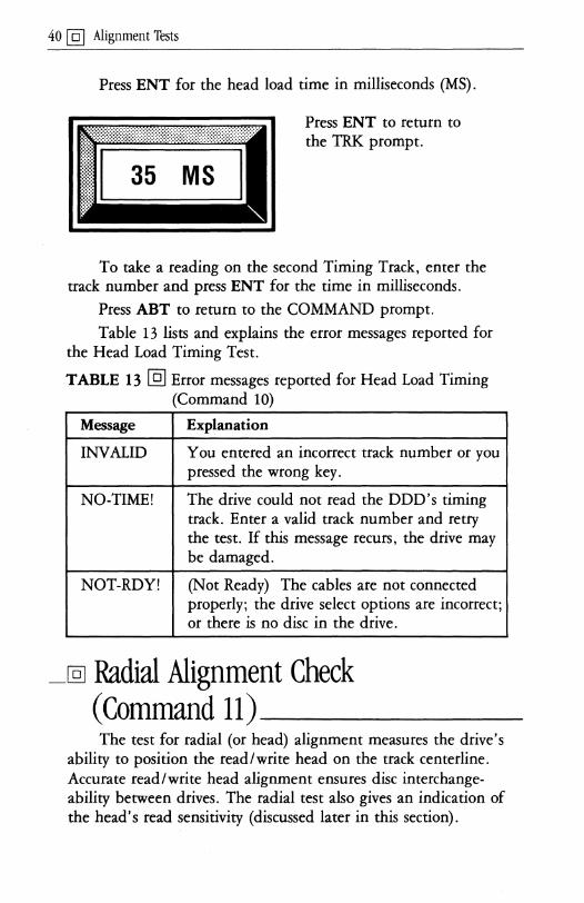
Press ENT for the head load time in milliseconds (MS).
Press ENT to return to the TRK prompt.
To take a reading on the second Timing Track, enter the track number and press ENT for the time in milliseconds.
Press ABT to return to the COMMAND prompt.
Table 13 lists and explains the error messages reported for the Head Load Timing Test.
TABLE 13 @] Error messages reported for Head Load Timing (Command 10)
Message Explanation
INVALID You entered an incorrect track number or you pressed the wrong key.
NO-TIME! The drive could not read the DOD's timing track. Enter a valid track number and retry the test. If this message recurs, the drive may be damaged.
NOT-RDY! (Not Ready) The cables are not connected properly; the drive select options are incorrect; or there is no disc in the drive.
_@l Radial Alignment Check (Command 11) _____ _ The test for radial (or head) alignment measures the drive's
ability to position the read/write head on the track centerline. Accurate read/write head alignment ensures disc interchangeability between drives. The radial test also gives an indication of the head's read sensitivity (discussed later in this section).

Alignment Tests @] 41
The PAT-2+ uses the DDD to evaluate how well the drive can read misaligned data. The DDD contains several Progressive Offset Tracks written with track and sector ID information on the track centerline. Data fields are radially displaced from the track centerline both away from (-) and toward ( + ) the spindle. (See Appendix C, Table C-4 for track locations. Your DDD data sheet also provides this information.)
A properly aligned drive can read sectors that are equally offset in opposite directions [( -) and ( + )]. Unsymmetrical readings indicate radial misalignment.
Checking radial alignment at several track locations indicates how consistent alignment is across the surface of the disc, showing errors in the drive positioner's linearity.
@] Radial Offset Values Test results are displayed as negative (-) and positive (+)
radial offset values. These values indicate the number of milliinches the head can read away from or toward the spindle. A drive that returns symmetrical offset values (-10 + 10, for example) shows optimal alignment. A drive that returns (for example) -7 +13, indicates a,n alignment problem. The head can read data 7 milli-inches off the track centerline away from the spindle and 13 milli-inches off track centerline toward the spindle. This indicates that the head is offset toward the spindle, and you should move it back. (See Appendix C, Table C-5 for a range of offset values. Your DDD data sheet also provides this information.)
@] Radial Delta The difference between the negative and positive offset
values reported is the Radial Delta. The Radial Delta shows the magnitude and direction of read/write head displacement from track centerline. A delta of 6 indicates greater misalignment than a delta of 3.
A drive that shows a slight misalignment may be usable. It is up to you to determine the value of delta that indicates an alignment problem. Use of an Analog Alignment Diskette (AAD) and an oscilloscope is recommended for drive alignment operations. (See Section 7 of this manual.)

42 @] Alignment Tests
@] Read Sensitivity In addition to reporting head alignment information, the
radial test indicates the read sensitivity of the drive head. Read sensitivity affects the radial offset values reported. As a sector is further displaced from track centerline, the amount of signal under the head decreases.
For example (given two drives of the same manufacture and model number): If Drive A returns offset values of -11 + 11 and Drive B returns -9 +9, both drives are properly aligned (centered on track). But the drive that returns the higher values is able to read data further off track centerline. Therefore, Drive A has a greater read sensitivity than Drive B.
Several factors can influence read sensitivity. • Normal wear on the DDD can reduce the amount of
signal (amplitude) it produces. • Amplitude is normally lower on the inner tracks. This
explains why inner track readings may be lower than outer track readings.
• Amplitude is occasionally lower on side 1 as compared to side O.
• The offset values returned can vary (by one or two digits) from one DOD to another. The causes of variation are: the unique interaction between a specific ODD and drive (head-to-disc compliance, for example); and manufacturing tolerances in DDDs.
• A build-up of dirt or oxide on the read/write head can reduce the read signal. Manufacturing tolerances in the read/write head, as well as in the drive's read channel electronics, can have similar effects.
• The drive's location in the computer system can significantly affect read sensitivity. A nearby CRT or switching power supply can produce interference in the read/write head. Often the result is lower or erratic offset values, particularly on the inner tracks where amplitudes generated from the disc are lower.

Alignment Tests @]43
@J Running the Radial Check Run the radial alignment test on the DDD's three
Progressive Offset Tracks (outer, middle and inner). (See Appendix C, Table C-4 for track locations.) Put the DDD into the drive. At the COMMAND prompt, enter the number 11 and press ENT. The test Command title, RADIAL ALIGNMENT CHECK, scrolls across the display.
If you selected the side-toggling option with Command 2, use the 0 and 1 keys to test alternate sides of your drive. The display indicates which side you selected.
When the track prompt appears:
Press ENT if the track number displayed is valid, or enter the correct Progressive Offset Track number from Appendix C.
Press ENT for a reading of the offset values.
Press ENT to return to the track prompt.
Run the radial alignment test at the remaining two Progressive Offset Track locations. (Enter a valid track number; press ENT for a reading.)
Press ABT to return to the COMMAND prompt.
Table 14 lists and explains the error messages reported for the Radial Alignment Check.

44 @J Alignment Tests
TABLE 14 @] Error messages reported for Radial Check (Command 11) and Azimuth Check (Command 12)
Message Explanation
INVAUD You entered an incorrect side number, or you pressed the wrong key.
NOT-RDY! (Not Ready) The cables are not connected properly; the drive select options are incorrect; or there is no disc in the drive.
RD-ERROR (Read Error) The tester could not read data from the track selected. Check that you entered the correct track number.
REQ-I;>DD (Requires DDD) Put the DDD into the drive; home the drive to track 0 and retry the test.
_@J Azimuth Check (Command 12) Azimuth alignment testing is available with these DDDs:
48 tpi, 67.5 tpi and 96 tpi (at 360 rpm only).
This test uses the DDD to verify that the head angle is positioned tangent to the test track. A drive's read/write head gap should be perpendicular to the radial magnetic transitions on a disc. The azimuth alignment test checks the head's ability to read data that has been increasingly rotated on the track both counterclockwise (-) and clockwise (+). When the read/write head is rotated from its ideal position, an angular error results.
The DDD's Azimuth Rotation Track has sectors that are rotated with increasing angular offsets in both directions (- and +) from the zero azimuth position. (See Appendix C, Table C-6 for track locations and maximum angular offsets. Your DDD data sheet also provides this information.)
Put the DDD into the drive. To start azimuth testing, enter the number 12 at the COMMAND prompt and press ENT. The Command title, AZIMUTH AUGNMENT CHECK, scrolls across the display and stops at the first prompt.

Alignment Tests @] 45
If you selected the side-toggling option with Command 2, use the 0 and 1 keys to test alternate sides of your drive. The tester shows which side you selected.
When the PAT -2+ displays the track prompt:
Press ENT if the track number displayed is valid, or enter the correct Azimuth Rotation Track from Appendix C.
Normally, head azimuth alignment is checked at an inner track because that is where drives are most sensitive to azimuth read errors.
Press ENT for test results in minutes (1 minute = 1/60 of a degree).
The values displayed represent the maximum angular offset which the drive head was able to read counterclockwise (-) and clockwise (+).
When a drive is properly aligned, the (-) and (+) values are balanced or nearly balanced. An unsymmetrical set of readings (-42 +32, for example) indicates an angular error between the read/write head and the Azimuth Rotation Track. (The head was unable to read skewed data equally.)
A reading of -42 +42 indicates optimal azimuth alignment because the head was able to read the maximum skewed data recorded on the ODD. A lower but equal set of readings (-32 +32, for example) indicates that the drive has

46 @] Alignment Tests
correct azimuth alignment but may have a read sensitivity or radial alignment problem. (See Radial Alignment [Command 11] for further information.)
Press ENT to return to the track prompt, or press ABT to return to the COMMAND prompt.
Table 14 lists and explains the error messages reported for the Azimuth Check.
_@] Hysteresis Check (Command 15)--This test checks the drive's ability to position the head
accurately to the same location on the DDD reference track after seeking to the track from opposite directions. The PAT-2+ performs the Hysteresis Check using a Progressive Offset Track on the DDD. (See Appendix C, Table C-4 for Progressive Offset Track locations. Your DDD data sheet also provides this information. )
An ideal hysteresis check reports a zero (0) error result. An error result other than zero indicates that the drive cannot reseek the same track location after being offset away from or toward the spindle. The offset number specifies the number of tracks for the head to move away from either side of the DDD reference track.
The illustrations provided are examples of displays for a 5 1,4 inch 48 tpi drive.
Put the DDD into the drive. At the COMMAND prompt, enter the number 15 and press ENT. The test Command title, HYSTERESIS CHECK, scrolls across the display and stops at the ftrst prompt.
If you selected the side-toggling option with Command 2, use the 0 and 1 keys to test alternate sides of your drive. The display indicates which side you selected.
When the track prompt appears:
Press ENT if the track number displayed is valid, or enter the correct Progressive Offset Track number from Appendix C.

Alignment Tests @] 47
Press ENT to bring up the prompt for the offset number.
Press ENT if the offset number displayed is valid, or enter a correct offset number from Appendix C.
TRK + OFFSET must not exceed the maximum track number for the drive. If TRK - OFFSET = less than 0, the head will go to track 0.
Press ENT to display the positioning error in milli-inches (MILS).
Press ENT to return to the track prompt; press ABT to return to the COMMAND prompt.
In the example given, the PAT-2+ begins the Hysteresis Check at track 16. Next it steps the head 10 tracks away from the spindle (to track 6). (The offset selected is 10.) The tester then repositions the head on the reference track (track 16), where it performs a read and computes the radial delta. (The delta is saved, but not displayed.)
Next the PAT-2+ steps the head 10 tracks toward the spindle (to track 26), then repositions the head on the reference track (track 16). The tester again performs a read and computes the radial delta. The difference between the two radial deltas divided by two is the hysteresis error that is displayed in milliinches.
Delia - Delta = Hysteresis error in mils 2
Table 15 lists and explains the error messages reported for the positioner hysteresis test.

48 @] Alignment Tests
TABLE 15 @] Error messages reported for Hysteresis Check (Command 15)
Message Explanation
INVALID You pressed the wrong key, or you entered an incorrect track or offset number.
NOT-RDYl (Not Ready) The cables are not connected properly; the drive select options are incorrect; or there is no disc in the drive.
RD-ERROR (Read Error) The tester could not read data from the track selected. Check that the track number is correct. Check that your setup parameters are correct.
REQ-DDD (Requires DDD) Put the DDD into the drive. Home the drive to track 0 and retry the test. Check that the track number is correct.
RNGERR (Ranging Error) The tester read data from the DDD. But it could not verify that the data was hysteresis alignment information; so it could not compute the hysteresis error.

49@]
Read/Write testing checks the overall data handling performance of your flexible disc drive. With four
Commands you can: • Verify read/write problems prior to repair. • Verify that the drive reads and writes correctly
following repair. • Look for intermittent problems while exercising
the drive.
This section explains how to: 1. Use Command 22 to format a data disc. 2. Use Command 19 to verify that the drive can read a
formatted disc. 3. Run the Random Seek/Read Test with Command 23, if
you suspect a read problem. 4. Run the Random Seek/Write/Read Test with Command
24, if you suspect both write and read problems.
_@] Read/Write Operations-___ _ To conduct any read/write operation on alternate sides of a
two-sided data disc, use Command 2 (Side Select). (See Section 3 of this manual.)
Press ENT or ABT to get to COMMAND mode. (If you want to stop an operation at any time, press ABT.) At the COMMAND prompt, home the drive to track 0 by pressing TKO. Then enter the Command number and begin the operation.
The illustrations in this section are examples of displays for a 51/4 inch 48 tpi drive with the tester's message switch ON, and MFM coding selected. It is recommended that you check your test results against the drive manufacturer's specifications.

50@] Read/Write Tests
@] Format Diskette (Command 22) Command 22 formats all or a specified portion of a disc
(according to your selections) and verifies the format. Use a data disc for this operation because the formatting process destroys whatever information the test disc contains.
At the COMMAND prompt, enter the number 22 and press ENT. The Command title, FORMAT DISKETTE, scrolls across the display and stops at the first prompt.
Press ENT to keep the number displayed, or enter the first track number to format (0-243). Press ENT.
To format an entire disc, select the disc's actual first and last track numbers. Do not exceed the maximum track number for the drive or the data disc. To format only one track, select the same number for both first track and last track.
Pressing ENT brings up the prompt for last track.
Press ENT to keep the number displayed, or enter the last track number to format. LTRK must be greater than or equal to FTRK. Press ENT.
Pressing ENT brings up the prompt for sector size.
Press ENT to keep the number displayed, or press 0 until the desired sector size is displayed (see Table 16). Press ENT.

Read/Write Tests [Q] 51
Table 16 lists sector sizes with the number of sectors that may be written on an individual track in single (FM) as well as double (MFM) density.
TABLE 16 [Q] Maximum number of sectors by RPM speed
Maximum Number of Sectors by RPM Speed
300 RPM 360 RPM 600 RPM 5~" & 3%" 8" & 5%" 31h"
Sector Single Double Single Double Single Double Size Density Density Density Density Density Density
128 byte 16 25 26 40 16 25
256 byte 9 16 16 26 9 16
512 byte 5 9 8 16 5 9
1024 byte 2 5 4 8 2 5
Pressing ENT brings up the prompt for the repeating pattern, which represents the data that fills the sectors.
Press ENT to record the displayed pattern as sector data on the disc. Or, press 0 until the desired pattern is displayed (see Table 17). Press ENT to record the pattern as sector data on the disc.

52 @] Read/Write Tests
TABLE 17 @] Five repeating patterns defined
Sector Data
Repeating Pattern Definition
ES ES ES Normal single density format pattern (PM)
40 40 40 Normal double density format pattern (MFM)
? ? ? ASCII question marks
DB 6D B6 "Worst case" data recovery pattern commonly used with double density (MFM) formats
92 49 24 "Worst case" data recovery pattern commonly used with single density (FM) formats
-
Pressing ENT also brings up the first sector prompt.
Press ENT to keep the sector number displayed. Or, enter the first sector number to format. Press ENT.
Pressing ENT also brings up the last sector prompt.
Press ENT to keep the sector number displayed. Or, enter the last sector number to format. Press ENT.
LSEC must be greater than or equal to FSEC. Do not exceed the maximum number of sectors for your drive, or all of the sectors will not fit on the track.
The message INSERT DISKETTE AND PRESS "ENT" scrolls across the display. Put a data disc into the drive and press ENT. The tester displays each track number it is formatting: TRK = 0, 1, 2, etc.

Read/Write Tests @] 53
When the last track has been formatted without error, the message INSERT DISKETTE AND PRESS "ENT' , scrolls across the display. To continue formatting, put another data disc into the drive and press ENT.
To report an error, the tester displays the track, sector and side where the format failure occurred, along with an appropriate error message. For example, TRK = 38, SEC = 6, SIDE = 1, LOST REC, Table 18 lists and explains the error messages.
Press ABT to return to the COMMAND prompt.
TABLE 18 @lError messages reported for Format Diskette (Command 22) and Verify Diskette Format (Command 19)
Message CMD# Explanation
CRC ERR 22, A Cyclic Redundancy Check (CRC) 19 revealed a bad sector on the disc.
Repeat the Command. (See NOTE.)
DATA-REQ 22, (Data Request) Retry the 19 Command. (See NOTE .) If
message recurs, tester may be damaged.
FDC BUSY 22, (Floppy Drive Controller Busy) 19 Tester could not locate the record to
be verified. Increase number of retries selected (Setup Parameters, Command 0). Repeat the Command. (See NOTE.)
INVALID 22, You entered an incorrect value; or 19 you pressed SEQ or TKO.
(continued)

54 @] Read/Write Tests
TABLE 18 @] Error messages reported for Format Diskette (Command 22) and Verify Diskette Format (Command 19) (continued)
Message CMD# Explanation
L-DATA 22, (Lost Data) The data to be verified 19 was lost. Repeat the Command.
(See NOTE below.) If message recurs, tester may be damaged.
LOST REC 22, (Lost Record) A record that could 19 not be written or read is lost. For
CMD #22, retry. (See NOTE below.) For CMD #19, reformat the track or sector.
NOT HOME 19 The drive cannot position the read/write head at track 0 and cannot locate the track 0 sensor. Review your Setup Parameters (Command 0). Check that a disc is in the drive. If the message recurs, the drive may be damaged.
NOT-RDYl 22, (Not Ready) The cables are not 19 connected properly; the drive select
options are incorrect; or there is no disc in the drive.
UNKNOWN 22, A power surge or similar event 19 caused the tester to receive
erroneous information during an operation. Repeat the Command. (See NOTE below.)
(continued)

Read/Write Tests @] 55
TABLE 18 @] Error messages reported for Format Diskette (Command 22) and Verify Diskette Format (Command 19) (continued)
Message CMD# Explanation
WR-PROT 22 (W rite-Protected) The disc is write-protected and cannot be written to; or there is a problem in the drive's write-protect circuit. To write-enable, cover the notch on 8" discs; uncover the notch on 5If4" discs; move the write-enable tab to the closed hole position on 31fz" discs.
NOTE: (For CMD #22) Press 0 to reformat the entire track. Press 1 to bypass the error and move to the next sector to continue formatting. Press ENT to format another disc if the tester has reached the last track specified. Or, press ENT to resume formatting on the next specified track. Press ABT to return to the COMMAND prompt.
NOTE: (For CMD #19) Press 0 to verify the entire track. Press 1 to bypass the error and move to the next sector to continue verifying. Press ENT to verify another disc if the tester has reached the last track specified. Or, press ENT to continue verifying on the next specified track. Press ABT to return to the COMMAND prompt.
@] Verify Diskette Format (Command 19) This command checks the drive's ability to read formatted
sectors, tracks or entire discs (according to your selections). Command 19 verifies:
• that the drive is compatible with a standard formatted data disc.
• that a data disc is formatted properly.
When you use this Command with a properly functioning drive, nothing is recorded on the disc.
At the COMMAND prompt, enter the number 19 and press ENT. The Command title, VERIFY DISKETTE FORMAT, scrolls across the display and stops at the first prompt.

56 @] Read/Write Tests
Press ENT to keep the number displayed. Or, enter the first track number to verify (0-243). Press ENT.
To verify an entire disc, select the disc's actual first and last track numbers. Do not exceed the maximum track number for the drive or the data disc. To verify only one track, select the same number for both first track and last track.
Pressing ENT brings up the prompt for last track.
Press ENT to keep the number displayed. Or, enter the last track number to verify. LTRK must be greater than or equal to FTRK. Press ENT.
Pressing ENT brings up the prompt for first sector.
Press ENT to keep the sector number displayed. Or, enter the first sector number to verify. Press ENT.
Pressing ENT brings up the prompt for last sector.
Press ENT to keep the sector number displayed. Or, enter the last sector number to verify. LSEC must be greater than or equal to FSEC. Press ENT.

Read/Write Tests @] 57
The message INSERT DISKETTE AND PRESS "ENT' , scrolls across the display. Put a formatted data disc into the drive and press ENT. The tester displays each track number it is verifying: TRK = 0, 1,2, etc.
When the last track has been verified without error, the message INSERT DISKETTE AND PRESS' 'ENT" scrolls across the display. To continue verifying, put another formatted data disc into the drive and press ENT.
If verification is unsuccessful, the PAT-2+ displays the track, sector and side where the read failure occurred, along with an appropriate error message. For example: TRK = 10, SEC = 14, SIDE = 0, CRC ERR. Table 18 in this section of the manual lists and explains the error messages.
@] Random Seek and Read Test (Command 23) This test seeks random tracks and reads random sectors
within a specified range on a formatted data disc and accumulates an error count. Use Command 23 to evaluate a drive's ability to read information from a disc.
Put a formatted data disc into the drive. At the COMMAND prompt, enter the number 23 and press ENT. The Command title, RANDOM SEEK AND READ TEST, scrolls across the display and stops at the prompt for first track.
Press ENT to keep the track number displayed. Or, enter the number (0-243) you want to specify for the first track. Press ENT.
When specifying first and last tracks, do not exceed the maximum track number for the drive or the data disc.
Pressing ENT brings up the prompt for last track.

58 @] Read/Write Tests
Press ENT to keep the number displayed. Or, enter the last track number (0-243) for your specified range. LTRK must be greater than or equal to FTRK. Press ENT.
Pressing ENT brings up the prompt for first sector.
Press ENT to keep the number displayed. Or, enter the number you want to specify for the first sector. Press ENT.
Pressing ENT brings up the prompt for last sector.
Press ENT to keep the number displayed. Or, enter the last sector number for your specified range. LSEC must be greater than or equal to FSEC. Press ENT.
The PAT-2+ continually displays the random track numbers it seeks to: TRK = 24, 23, 25, etc. If you selected the side-toggling option with Command 2, use the 0 and 1 keys to obtain an error count on alternate sides of a two-sided disc. The display indicates which side you selected.
Table 19 illustrates how to use keys-O through 5 to display test results.

Read/Write Tests @] 59
TABLE 19 @] Keyboard functions for Random Seek/Read (Command 23) and Random Seek/Write/Read (Command 24)
Key Function
0 Displays the total error count for Side o. CNT=O
1 Displays the total error count for Side 1. CNT=O
2 Displays the number of Cyclic Redundancy Check errors for the side selected. CRC = 0
3 Displays the number of Lost Records for the side selected. LlR = 0
4 Displays the total number of errors (other than CRC and LlR errors) found on the side selected. OTH = 0 For example: pulling the disc out of the drive during the test causes a write fault, which is counted as an "Other."
5 Displays the total number of errors on both sides of the disc. TOT = 0
When the tester reports an error, it seeks the drive to the track 0 sensor for a known starting point. This action prevents an accumulating error count based on the first error.
You can press keys 0 through 5 in any order. Press ENT to return to the TRK display. Press ABT to return to the COMMAND prompt.
Table 20 explains the two error messages reported for Command 23.

60 @] Read/Write Tests
TABLE 20 @] Error messages reported for Random Seek/Read (Command 23) and Random Seek/Write/Read (Command 24)
Message CMD# Explanation
INVALID 23, You entered an incorrect value or 24 pressed the wrong key during the
test.
NOT-RDY 23, (The drive is not ready) The cables 24 are not connected properly; the
drive select options are incorrect; or there is no disc in the drive.
WR-PROT 24 (Write-Protected) The disc is write-protected and cannot be written to; or there is a problem in the drive's write-protect circuit. To write-enable, cover the notch on 8" discs; uncover the notch on 51/4" discs; move the write-enable tab to the closed hole position on 3%" discs.
@] Random Seek, Write and Read Test (Command 24) This test seeks random tracks on a formatted data disc, then
writes and reads random sectors within a selected range and accumulates an error count. Use Command 24 to evaluate a drive's ability to write to and read from a disc.
To begin, put a formatted data disc into the drive. At the COMMAND prompt, enter the number 24 and press ENT. The Command title, RANDOM SEEK WRITE AND READ TEST, scrolls across the display and stops at the prompt for first track.
Press ENT to keep the number displayed. Or, enter the number (0-243) you want to specify for the first track. Press ~NT.

Read/Write Tests @] 61
When specifying first and last tracks, do not exceed the maximum track number for the drive or the data disc.
Pressing ENT brings up the prompt for last track.
Press ENT to keep the number displayed. Or, enter the last track number (0-243) for your specified range. LTRK must be greater than or equal to FTRK. Press ENT.
Pressing ENT brings up the prompt for first sector.
Press ENT to keep the number displayed. Or, enter the number you want to specify for the first sector. Press ENT.
Pressing ENT brings up the prompt for last sector.
Press ENT to keep the number displayed. Or, enter the last sector number for your specified range. LSEC must be greater than or equal to FSEC. Press ENT.
The PAT-2+ continually displays the random track numbers it seeks to:TRK = 19, 22, 39. If you selected the side-toggling option with Command 2, use the 0 and 1 keys to obtain an error count on alternate sides of a two-sided disc. The display indicates which side you selected.

62 @] Read/Write Tests
Table 19 in this section of the manual illustrates how to use keys 0 through 5 to display test results. You can press these keys in any order. Press ENT to return to the TRK display. Press ABT to return to the COMMAND prompt.
Table 20 in this section of the manual explains the three error messages reported for Command 24.

The Utilities
ThiS section explains how to use nine commands: • Seek to Track (CMD #3)· Locate Head (CMD #16) • Alternate Seek (CMD #4) • Stored Status (CMD #17) • Accordion Seek (CMD #13) • Present Status (CMD #18) • Step Rate (CMD #14) • Write Sector (CMD #20)
• Re-Write Sector (CMD #21)
By allowing you to exercise a flexible disc drive, these utilities aid alignment adjustments and general troubleshooting. An Analog Alignment Diskette (AAD) and an oscilloscope are recommended as useful tools for the experienced service technician.
The following information pertains to the use of 8 inch AADs.
• An 8 inch one-sided AAD has an "index 1" hole. • An 8 inch two-sided AAD has an "index 1" hole and
an "index 2" hole, so you can use it on both one-sided and two-sided drives.
When you use an 8 inch two-sided AAD for adjusting a two-sided drive, place a write protect label over the "index 1" hole. This action provides the optimum index transducer setting if two-sided soft-sectored media are used exclusively.
To begin an operation, press ENT or ABT to get to COMMAND mode. At the COMMAND prompt, press TKO to home the drive to track o. At any time during an operation, you can return to the COMMAND prompt by pressing ABT.

64 @] The Utilities
-@] Seek To Track (Command 3) In Command 3 the PAT-2+ positions the drive head to any
track (0-255) you specify on a disc. Use an AAD with this utility for drive adjustments. Later, you can verify adjustments with the tester and a DDD. To isolate a stepper motor problem, run Command 3 with a data disc in the drive.
Put your AAD or your data disc into the drive. At the COMMAND prompt, press 3 and ENT. The Command title, SEEK TO SELECTED TRACK, scrolls across the display and stops at the first prompt.
Press ENT to seek to the track number displayed. Or, enter another track (0-255) and press ENT.
Do not exceed the maximum tracks for the drive or the disc.
Pressing ENT brings up the Side prompt (if you selected the two-sided option with Command 2).
Press ENT to keep the side displayed. Or, enter the side number (0 or 1) to test. Press ENT.
Pressing ENT returns you to the TRK prompt. Each time you select a track, enter the track number and press ENT.
Press ABT to return to the COMMAND prompt.
The PAT-2+ reports one error message for Command 3: "INVALID." This message indicates that you specified a track number greater than 255, or you pressed the wrong key.

The Utilities @] 65
_@] Alternate Track Seek (Command 4)_ Command 4 lets you select any two tracks (0-255) on a disc
and move the drive head back and forth between them. This utility is useful for adjusting the track 0 sensor.
Put a data disc into the drive. At the COMMAND prompt, enter 4 and press ENT. The Command title, ALTERNATE TRACK SEEK, scrolls across the display and stops at the prompt for first track.
Press ENT to select the track displayed. Or, enter another track number (0-255) and press ENT.
When specifying first and last tracks, do not exceed the maximum tracks for the drive or the disc.
Pressing ENT brings up the prompt for last track.
Press ENT to select the track displayed. Or, enter another track number (0-255) and press ENT.
LTRK must be greater than or equal to FTRK.
Pressing ENT brings up the Side prompt (if you selected the two-sided option with Command 2).
Press ENT to keep the side displayed. Or, enter the side number (0 or 1) to test. Press ENT.

66 @l The Utilities
Pressing ENT brings up the prompt for "wait time," which specifies the delay (in milliseconds) between seeks.
Press ENT to keep the time displayed. Or, enter the desired delay (0-999 ms) and press ENT.
The drive's head alternates between the two tracks you specified, while the tester displays the track number where the head is currently positioned.
Pressing ENT returns you to the FTRK prompt. Pressing ABT returns you to the COMMAND prompt.
The PAT-2+ reports one error message for Command 4: "INVALID." This message indicates that you specified a track greater than 255; you pressed the wrong key; or LTRK is less than FTRK.
_@l Accordion Seek Test (Command 13)-The Accordion Seek Test performs a sequence of sweeps of
varying lengths. In the first sweep, the drive seeks from track 0 to the LTRK specified and takes a reading to verify its position. Then it returns to track 1 and takes another reading. With each sweep the distance between the target tracks decreases until the target tracks meet: For example:
First sweep: TRK 0 to TRK 6 to TRK 1. Second sweep: TRK 1 to TRK 5 to TRK 2. Third sweep: TRK 2 to TRK 4 to TRK 3. The target tracks meet at TRK 3.
Then the process reverses to increase the distance between the target tracks.
Put a formatted data disc into the drive. At the COMMAND prompt, enter 13 and press ENT. The Command

The Utilities @] 67
title, ACCORDION SEEK TEST, scrolls across the display and stops at the prompt for last track.
Press ENT to keep the track displayed. Or, enter the desired number (0-255) for LTRK and press ENT.
Pressing ENT brings up the Side prompt (if you selected the two-sided option with Command 2).
Press ENT to keep the side displayed. Or, enter the side number (0 or 1) to test. Press ENT.
Pressing ENT starts the sequence of sweeps. The tester rapidly displays the track numbers it seeks to. The sequence continues until you stop the test by pressing ENT or ABT. Pressing ENT returns you to the LTRK prompt. Pressing ABT returns you to the COMMAND prompt. If an error occurs during the test, the PAT-2+ displays an appropriate error message and the LTRK number where it found the error.

68 @] The Utilities
Table 21 lists and explains the error messages reported for Command 13.
TABLE 21 @J Error messages reported for the Accordion Seek Test (Command 13) and the Step Rate Test (Command 14)
Message Explanation
INVALID You specified a track number greater than 255; or you pressed the wrong key.
NOT HOME The drive cannot position the read/write head at track 0 and cannot locate the track 0 sensor. Review your Setup Parameters (Command 0). Check that a formatted disc is in the drive. If this message recurs, the drive may be damaged.
NOT-RDY! (The drive is not ready.) The cables are not connected properly; the drive select options are incorrect; or there is no disc in the drive.
RD-ERROR (Read Error) (Applies to Command 13) The tester could not read data from the LTRK specified. Check that the track number is correct.
SEEK ERR (Seek Error) The controller track register differed from the track ID read from the disc. Check the step rate parameter you selected in Command o. The step rate may be too fast or too slow. Too slow a step rate can produce resonances that cause mis-stepping.
--@] Step Rate Test (Command 14) Command 14 determines the drive's fastest step rate (in
increments of one millisecond) during alternate seek conditions. This test does not change the step rate selected in Setup Parameters (Command 0). The maximum rate determined by the Step Rate Test may not be valid under all operating conditions. Use Command 14 to find problems caused by resonance.

The Utilities @] 69
Put a formatted data disc into the drive. At the COMMAND prompt, enter 14 and press ENT. The Command title, STEP RATE TEST, scrolls across the display and stops at the first prompt.
Press ENT to keep the rate displayed. Or, enter the desired starting step rate (0-99) and press ENT.
Pressing ENT brings up the prompt for last track.
Press ENT to keep the track displayed. Or, enter the desired number (0-255) for LTRK and press ENT.
LTRK must not exceed the maximum tracks for the drive or the disc.
Pressing ENT brings up the Side prompt (if you selected the two-sided option with Command 2).
Press ENT to keep the side displayed. Or, enter the side number (0 or 1) to test. Press ENT.
The tester displays the changing step rate as the speed increases (and the step time decreases) until the drive is unable to position the head to the specified track. For example: STEP = 20, 19, 18, 17, etc.
When the drive cannot position the head as you specified, the tester displays an error message (NOT HOME, for example)

70 @l The Utilities
and the last step rate at which the drive operated successfully (STEP = 3). The test continues to seek at that rate until you:
• Enter 0 to speed up the step rate; or • Enter 1 to slow the step rate; or • Press ENT to enter a new starting step rate; or • Press ABT to return to the COMMAND prompt.
During this test, the drive alternately seeks the track 0 sensor and the last track (LTRK). The operation begins at the step rate you selected, but this rate decreases in one millisecond increments as the test progresses. The process continues until the drive no longer can locate the track 0 sensor, or until a read error occurs on the LTRK selected.
The drive may reach a rate resonance point that causes a seek error at the step rate below the maximum rate. Try speeding up the rate to optimize drive performance.
Table 21 in this section of the manual lists and explains the error messages reported for Command 14.
_@l Locate Head Position (Command 16) Command 16 measures the drive's compatibility with a
standard formatted data disc. It does so by reading the true track location of the head from the disc. You can also use this Command to test the Track 0 Limiter; additional information appears later in this discussion.
Put a formatted data disc into the drive. At the COMMAND prompt, enter 16 and press ENT. The Command title, LOCATE HEAD POSITION, scrolls across the display and stops at the first prompt.
Press ENT to keep the track displayed. Or, enter the track number (0-255) where you want the head positioned. Press ENT.
Do not exceed the maximum tracks for the drive or the disc.

The Utilities @] 71
The drive moves the head to the track you specified, and the PAT-2+ displays the head's true track location (read from the disc). For example, LaC = 16.
You have a number of keyboard options at this point in the operation.
• Press ENT to toggle between the head's true location (LOC) and the track number you specified (TRK.).
• Press 0 to select Side o. • Press 1 to select Side 1. • Press 2 to move the head away from the spindle one
track at a time. For example, pressing 2 changes TRK= 16 to TRK= 15; and LOC= 15.
• Press 3 to move the head toward the spindle one track at a time. For example, pressing 3 changes TRK= 15 to TRK= 16; and LOC= 16.
• Press 4 to reset the head at the track 0 sensor LOC=O.
As mentioned earlier, Command 16 is useful for testing the Track 0 Limiter. Press the 2 key until the tester displays: TRK = o. Then press 2 again to move the head against the Track 0 Limiter. The tester displays: TRK = -1. Press ENT to toggle the display to Lac. If LaC = 0, the Track 0 Limiter is functioning properly. If the tester displays RD-ERROR, the head has moved beyond Track 0, and the Track 0 Limiter needs adjustment.
Table 22 lists and explains the error messages reported for Command 16.

72 @] The Utilities
TABLE 22 @] Error messages reported for Locate Head Position (Command 16)
Message Explanation
INVALID You specified a track number greater than 255; or you pressed the wrong key.
NOT HOME The drive cannot position the read/write head at track 0 and cannot locate the track 0 sensor. Review your Setup Parameters (Command 0). Check that a formatted disc is in the drive. If this message recurs, the drive may be damaged.
NOT-RDYl (The drive is not ready.) The cables are not connected properly; the drive select options are incorrect; or there is no disc in the drive.
RD-ERROR (Read Error) The tester could not read data from the track specified. Check that the track number is correct.
-@]Stored Status (Command 17)---Use Command 17 to display the floppy disc controller
status (in binary number format) from the last read or write operation performed. At the COMMAND prompt, enter 17 and press ENT. The Command tide, STATUS LAST READ OR WRITE, scrolls across the display. Next, the tester displays the disc controller status. For example:
Bit positions:
7 6 5 4 3 2 1 0
00000 000
The status bits displayed have different meanings that are determined by the last Command you entered. Table 24 in this section of the manual provides definitions for status bits. Table 23 lists the status words used with the PAT-2+ Commands.

The Utilities @] 73
The tester reports one error message for Command 17: "INVALID." This message indicates that you pressed the wrong key.
Press ABT to return to the COMMAND prompt.
TABLE 23 @] Status words used with PAT-2+ Commands
Command # and Title Status Word
#1 Select Drive Clear Status
#2 Select Side Clear Status
#3 Seek To Track Clear Status
#4 Alternate Seek Clear Status
#5 Disk Centering Read Sector
#6 Spindle Speed Clear Status
#7 Index Pulse Width Clear Status
#8 Index Timing Read Address
#9 Head Skew Read Address
#lO Head Load Timing Read Address
#11 Radial Check Read Sector
#12 Azimuth Check Read Sector
#13 Accordion Seek Read Address
#14 Step Rate Read Address
#15 Hysteresis Check Read Sector
#16 Locate Head Read Address
#17 Stored Status Current Status
#18 Present Status Clear Status
#19 Verify Disk Format Read Sector
#20 Write Sector Write Sector
#21 Re-Write Sector Read Sector/Write Sector
#22 Format Disk Read Sector
#23 Random Seek/Read Read Sector
(continued)

74 @] The Utilities
TABLE 23 @] Status words used with PAT-2+ Commands (continued)
Command # and Title Status Word
#24 Random Seek/Write/Read Write Sector/Read Sector
#25 Write Pattern Clear Status or Write Track
#26 Constant Write Clear Status or Write Track
#27 Tap Tap Test Clear Status
#28 Sequence Selects Clear Status
#29 Toggle Side Selects Clear Status
#30 Display Sector Data Clear Status

The Utilities @] 75
TABLE 24 @] Status bits defined
Bit Positions: 7 6 5 4 3 2 1 0
Binary Format: Oil Oil 011 011 Oil Oil Oil 011
Status Word:
CLEAR 'Not Write Head Seek CRC Trk 0 Index Busy STATUS Ready Protect Loaded Err Err
READ 'Not NIA Record Record CRC Lost Data Busy SECTOR Ready Type Not Err Data Request
Found
READ 'Not Write NIA Record CRC Lost Data Busy ADDRESS Ready Protect Not Err Data Request
Found
WRITE 'Not Write NIA Record CRC Lost Data Busy SECTOR Ready Protect Not Err Data Request
Found
WRITE 'Not Write NIA NIA NIA Lost Data Busy TRACK Ready Protect Data Request
, Applies only to 8 inch drives.
In all binary status word displays, 0 = False and 1 = True.
The diagram that follows (for the Status Word "Write Track' ') illustrates the information provided in Table 24.
STATUS WORD (Write Track)
N/A Write Protect
N/A N/A
Not Ready (applies only to 8 inch drives)
Busy Data Request
Lost Data

76 @] The Utilities
-@] Present Status (Command 18) This Command clears the controller status and displays the
status word in binary number format, constantly updating this information. Use Command 18 to troubleshoot the Write Protect and Ready status lines.
At the COMMAND prompt, enter 18 and press ENT. The Command title, CLEARED STATUS, scrolls across the display. Next, the tester shows you the clear status word. For example:
Bit positions:
7 6 543 2 1 0
o 0 100 1 0 0
Refer to Table 24 in this section of the manual for a definition of the status bits. Table 23 in this section of the manual lists the status words used with the PAT-2+ Commands.
The tester reports one error message for Command 18: "INVALID." This message indicates that you pressed the wrong key.
Press ABT to return to the COMMAND prompt.
-@]Write Sector (Command 20) ---This Command writes new data to a sector. With Com
mand 20 you can repair a data or a system disc by recording a repeating pattern on a bad sector. This operation allows you to select a repeating pattern and write it to a sector you specify. For example: If you find a bad sector with Command 19, you can repair the disc by recording a ??? pattern in the bad sector. The pattern is filed, and the system then accepts the disc containing that pattern. You can save all data on the disc except the sector containing the ??? pattern.
If the sector ID has been damaged, you cannot use Command 20 to repair the disc. You must reformat the track.

The Utilities @] 77
To repair a disc, put it into the drive. At the COMMAND prompt, enter 20 and press ENT. The Command title, WRITE SECTOR, scrolls across the display and stops at the first prompt.
Press ENT to select the track number displayed. Or, enter the desired track number (0-255) and press ENT.
Do not exceed the maximum tracks for the drive or the disc.
Pressing ENT brings up the next prompt.
Press ENT to select the sector number displayed. Or, enter the desired sector number and press ENT.
Pressing ENT brings up the prompt for the repeating pattern (the data that fills the sectors).
Press ENT to record the displayed pattern as sector data on the disc. Or, press 0 until the desired pattern is displayed (see Table 25). Press ENT to record the pattern as sector data on the disc.

78 @] The Utilities
TABLE 25 @] Five repeating patterns defined
Sector Data
Repeating Pattern Definition
E5 E5 E5 Normal single density format pattern (FM)
40 40 40 Normal double density format pattern (MFM)
? ? ? ASCII question marks
DB 6D B6 "Worst case" data recovery pattern commonly used with double density (MFM) formats
92 49 24 "Worst case" data recovery pattern commonly used with single density (FM) formats
Pressing ENT brings up the Side prompt (if you selected the two-sided option with Command 2). For example:
Press ENT to keep the side displayed. Or, enter the side number (0 or 1) to test. Press ENT.
Pressing ENT starts the write operation. When the tester finishes the operation, it displays the message' 'GOOD WR." This message indicates that the PAT-2+ sent the selected pattern to the drive. If the write operation is unsuccessful, the tester displays an error message and the track, sector and side where the error occurred. Table 26 in this section of the manual lists and explains the error messages reported for Command 20.
After completing the write operation, the tester again displays the TRK prompt. Enter another track number to
continue, or press ABT to return to the COMMAND prompt.

The Utilities @] 79
TABLE 26 @] Error messages reported for Write Sector (Command 20) and Re-Write Sector (Command 21)
Message Explanation
CRC ERR A Cyclic Redundancy Check revealed a bad sector on the disc. Try to rewrite the sector with Command 21 (Re-write Sector). Then repeat Command 20. If this error occurs with Command 21, the disc may be damaged or the entire track requires reformatting.
DATA-REQ (Data Request) Repeat the Command. If this message recurs, the tester may be damaged.
FDC BUSY (Floppy Disc Controller Busy) Tester could not locate the record to be written. Increase number of retries selected (Setup Parameters, Command 0) and repeat the Command.
INVALID You entered an incorrect value or you pressed the wrong key.
L-DATA (Lost Data) The data to be verified was lost. Repeat the Command. If message recurs, tester may be damaged.
LOST REC (Lost Record) A record that could not be written or read was lost. Reformat the track.
NOT-RDY! The drive is not ready. The cables are not connected properly; the drive select options are incorrect; or there is no disc in the drive.
NOT The sector cannot be rewritten. REPAIRED
UNKNOWN A power surge or similar event caused the tester to receive erroneous information during an operation. Repeat the Command.
(continued)

80 []J The Utilities
TABLE 26 []J Error messages reported for Write Sector (Command 20) and Re-Write Sector (Command 21) (continued)
Message Explanation
WR-PROT (Write-Protected) The disc is write-protected and cannot be written to; or there is a problem in the drive's write-protect circuit. To write-enable, cover the notch on 8" discs; uncover the notch on 51/4" discs; move the write-enable tab to the closed hole position on 3 1f2" discs.
_[]J Re-Write Sector (Command 21) Use this Command to repair a disc. If you cannot make the
repair with Command 21, then try Command 20. In Command 21, the PAT-2+ reads the existing data on a track and sector you specify and rewrites it. Instead of losing a complete sector of data, the tester tries to read the data, ignoring the Cyclic Redundancy Check. Then it rewrites the data to save as much information as possible.
Put the disc for repair into the drive. Enter 21 and press ENT. The Command title, RE-WRITE SECTOR, scrolls across the display and stops at the first prompt.
Press ENT to select the track number displayed. Or, enter the desired track (0-255) and press ENT.

disc.
The Utilities @] 81
Do not exceed the maximum tracks for the drive or the
Pressing ENT brings up the next prompt.
Press ENT to select the sector number displayed. Or, enter the desired sector number and press ENT.
Pressing ENT brings up the Side prompt (if you selected the two-sided option with Command 2).
Press ENT to select the side number displayed. Or, enter the desired side (0 or 1) and press ENT.
When you press ENT, the tester starts to read data from the sector you specified and then rewrites the data to that same sector. If the write operation is successful, the tester displays the message "GOOD WR." Otherwise, the PAT-2+ displays an error message along with the track, sector and side where the write failure occurred. Table 26 in this section of the manual lists and explains the error messages reported for Command 21.
After completing the write operation, the tester again displays the TRK prompt. Enter another track number to continue, or press ABT to return to the COMMAND prompt.

82@]

83@] Drive Troubleshooting
There are six Commands useful for drive troubleshooting: • Write Pattern (CMD #25) • Sequence Selects (CMD #28) • Constant Write (CMD #26) • Toggle Side (CMD #29) • Tap Test (CMD #27) • Display Sector (CMD #30)
An oscilloscope may be useful for viewing drive operations.
To begin an operation, press ENT or ABT to go to COMMAND mode. (To return to COMMAND mode at any time, press ABT.) At the COMMAND prompt, press TKO to home the drive to track o.
The illustrations in this section are examples of displays for a 51f4 inch 48 tpi drive with the tester's message switch ON.
-@] Write Pattern (Command 25) Command 25 writes a selected frequency or pattern on a
specified track and side of a disc from index to index. The process writes over any existing data on the specified track and side. Use a data disc for writing, and an oscilloscope for viewing readback signals.
Put your data disc into the drive. At the COMMAND prompt, enter the number 25 and press ENT. The Command title, WRITE PATTERN ONE REVOLUTION, scrolls across the display and stops at the first prompt.

84 [Q] Drive Troubleshooting
Press ENT to keep the number displayed. Or, enter another track number (0-255). Do not exceed the maximum tracks for the drive or the data disc. Press ENT.
Pressing ENT brings up the Side prompt (if you selected the two-sided option with Command 2).
Press ENT to keep the side displayed. Or, enter the side number (0 or 1) you want to
test. Press ENT.
Pressing ENT brings up the prompt for the frequency or pattern to be written. For example:
Press ENT to keep the selection displayed. Or, use keys 0-7 to make an alternate choice (see Table 27). Press ENT.
Keys 0 through 6 select frequencies; key 7 selects the "worst case" pattern.

Drive Troubleshooting @] 85
TABLE 27 @] Keyboard functions for Write Pattern (Command 25) and Constant Write (Command 26)
Key Function at the Interface Inside the Drive (Displayed by the Tester)
0 ERASE NO SIGNAL
1 31.25 KHZ 15.63 KHZ
2 62.50 KHZ 31.25 KHZ
3 125 KHZ 62.50 KHZ
4 250 KHZ 125 KHZ
5 500 KHZ 250 KHZ
6 1.0 MHZ 500 KHZ
7 DB 6D B6 - Double (' 'Worst case" pattern) Density (MFM) repeating pattern
or 92 49 24 - Single Density ("Worst case" pattern) (FM) repeating pattern
During the write operation, the PAT -2+ displays the message: WRITING. If this message stays on the display, the tester has not received an index pulse from the drive. When the tester finishes the operation, it displays the message: GOOD WR. This message indicates only that the PAT -2+ sent the selected frequency or pattern to the drive. (A read operation was not performed.)
Following the "GOOD WR" message, the tester again displays the TRK prompt. Enter another track number to continue, or press ABT to return to the COMMAND prompt.
Table 28 lists and explains the error messages reported for the Write Pattern test.

86 @] Drive Troubleshooting
TABLE 28 @] Error messages reported for Write Pattern (Command 25) and Constant Write (Command 26)
M~ssag~ E:x:planation . . .....
INVALID You entered a track number that exceeds the maximum tracks for the drive or the data disc; or you pressed the wrong key.
NOT-RDYl (Not Ready) The cables are not connected properly; the drive select options are incorrect; or there is no disc in the drive.
WR-PROT (Write-Protected) The disc is write-protected and cannot be written to; or there is a problem in the drive's write-protect circuit. To write-enable, cover the notch on 8" discs; uncover the notch on 51/4" discs; move the write-enable tab to the closed hole position on 3%" discs.
_@l Constant Pattern Write (Command 26)_ Although similar to Command 25 (Write Pattern),
Command 26 (Constant Write) repeatedly writes a frequency or pattern on a specified track and side from index to index. This process also writes over any existing data on the track and side specified. Use a data disc and an oscilloscope with Command 26 to check a drive's write circuitry and to troubleshoot additional problem areas.
Put your data disc into the drive. At the COMMAND prompt, enter the number 26 and press ENT. The Command title, CONSTANT PATTERN WRITE, scrolls across the display and stops at the first prompt.

Drive Troubleshooting @] 87
Press ENT to keep the number displayed. Or, enter another track number (0-255). Do not exceed the maximum tracks for the drive or the data disc. Press ENT.
Pressing ENT brings up the Side prompt (if you selected the two-sided option with Command 2).
Press ENT to keep the side displayed. Or, enter the side number (0 or 1) you want to test and press ENT.
Pressing ENT brings up the prompt for the frequency or pattern to be written. For example:
Press ENT to keep the selection displayed. Or, use keys 0-7 to make an alternate choice (see Table 27 in this section of the manual). Press ENT.
Keys 0 through 6 select frequencies; key 7 selects the "worst case" pattern. (See Table 27 in this section of the manual.)
During the write operation, the tester displays the message: WRITING and continues to display this message until you press ENT or ABT. Pressing ENT returns you to the TRK prompt. Enter another track number to continue. Pressing ABT returns you to the COMMAND prompt.
Table 28 in this section of the manual lists and explains the error messages reported for the Constant Write test.

88 @] Drive Troubleshooting
-@] Tap Tap Media Test (Command 27) -Use a data disc with the Tap test to check for media wear.
In this operation, the drive head loads at the same position on the disc with every revolution. When the PAT-2+ receives an index pulse from the drive, it signals the drive to load the head. The drive is delayed according to the' 'wait time" you select. ("Wait time" is measured from the index pulse). This delay allows the drive to load and unload the head repeatedly at the same position.
Command 27 requires: (1) that the drive to be tested must have a head load solenoid; and (2) that 51/4 inch and 3112 inch drives must have a separate head load line on Pin #4.
To begin, put your data disc into the drive. At the COMMAND prompt, enter the number 27 and press ENT. The Command title, TAP TAP MEDIA TEST, scrolls across the display and stops at the first prompt.
Press ENT to keep the number displayed. Or, enter another track number (0-255). Do not exceed the maximum tracks for the drive or the data disc. Press ENT.
Pressing ENT brings up the prompt for "wait" time.
Press ENT to keep the time displayed. Or, enter the desired delay (0-999 milliseconds). Press ENT.
The delay ("wait time") plus the drive's normal head load time should not exceed the time between index pulses. Too long a delay causes the taps (head loads) to accumulate at a slower rate with every other revolution.

Drive Troubleshooting @] 89
Pressing ENT brings up the Side prompt (if you selected the two-sided option with Command 2).
Press ENT to keep the side displayed. Or, enter the side number (0 or 1) to test. Press ENT.
The message "BUSY" flashes on the display. Next, the tester shows the total count of taps (head loads) and continues to display them (1,2,3,4,5, etc.) until you press ENT or ABT. Pressing ENT returns you to the TRK prompt. Pressing ABT returns you to the COMMAND prompt.
Command 27 does not perform a read operation, so you need not run the Tap Test on the opposite side of your data disc. When you have tested the desired number of taps, stop and visually examine your disc for wear.
Command 27 does not function properly if the drive is not ready, or if the tester does not receive an index pulse from the drive. Table 29 lists and explains the error messages reponed for the Tap Test.
TABLE 29 @] Error messages reponed for Tap Tap Test (Command 27)
Message Explanation
INVALID You entered a track number that exceeds the maximum tracks for the drive or the data disc; you entered a "wait time" outside the 0-999 millisecond range; or you entered a number other than 0 or 1 to select Side.
NOT-RDY! The drive is not ready. The cables are not connected properly; the drive select options are incorrect; or there is no disc in the drive.

90 @l Drive Troubleshooting
_@l Sequence Drive Selects (Command 28)_ This command tests the drive select circuits of a flexible
disc drive by sequentially selecting four drives. Use Commalld28: .... . ..- ... ..... .
• For troubleshooting the drive select logic. • For determining the drive select number on an unknown
drive by watching the tester's display as each drive number is selected. Generally, you can determine the drive select signal by observing the drive activity light.
At the COMMAND prompt, enter the number 28 and press ENT. The Command title, SEQUENCE DRIVE SELECTS, scrolls across the display and stops at the first prompt.
Press ENT to keep the time displayed. Or, enter the desired delay (0-999 milliseconds). Press ENT.
The delay (' 'wait' ') specifies the length of time the tester waits to select each drive. Too shott a "wait time" operates the selecting sequence faster than you can follow.
The tester's display indicates that it is selecting the drives in sequence: DRIVE = 1,2,3,4. Press ENT to return to the WAIT prompt, if you want to change the delay. Press ABT to return to the COMMAND prompt.
The PAT-2+ reports one error message for Command 28: "INVALID. " This message indicates that you entered an incorrect value or pressed the wrong key.
__ @l Toggle Side Selects (Command 29) _ Command 29 lets you toggle between the two heads on a
two-sided drive. You can verify the head select circuitry and compare head output by observing signals from a disc, such as an Analog Alignment Diskette (AAD). An AAD and an oscilloscope are useful aids with this operation.

Drive Troubleshooting @] 91
At the COMMAND prompt, enter the number 29 and press ENT. The Command title, TOGGLE SIDE SELECTS, scrolls across the display and stops at the first prompt.
Press ENT to keep the number displayed. Or, enter another track number (0-255). Do not exceed the maximum tracks for the drive or the disc. Press ENT.
Pressing ENT brings up the prompt for "wait time," which specifies how many milliseconds the tester will wait before selecting the alternate head.
Press ENT to keep the time displayed. Or, enter the desired delay ( 0-999 milliseconds). Press ENT.
The drive begins toggling between the heads, and the tester displays the side currently selected. Too short a "wait time" operates the toggling activity faster than you can follow.
Press ENT to return to the TRK prompt. Press ABT to return to the COMMAND prompt.
The PAT-2+ reports one error message for Command 29: "IN· VALID. " This message indicates that you pressed the wrong key or entered an incorrect value.

92 @] Drive Troubleshooting
_@] Display Sector Data (Command 30)-This command displays all data, byte by byte, that has
been written to a specific sector of a disc. With Command 30 you can:
• Vertty that a data pattern wntten to a specrlic track and sector (with Command 20) was correctly written.
• Determine a disc's sector size.
To begin, put a formatted data disc into the drive. At the COMMAND prompt, enter the number 30 and press ENT. The Command title, DISPLAY SECTOR DATA, scrolls across the display and stops at the first prompt.
Press ENT to keep the number displayed. Or, enter another track number (0-255). Do not exceed the maximum tracks for the drive or the data disc. Press ENT.
Pressing ENT brings up the sector prompt.
Press ENT to keep the number displayed. Or, enter another sector number and press ENT.
Pressing ENT brings up the Side prompt (if you selected the two-sided option with Command 2).

Drive Troubleshooting @] 93
Press ENT to keep the side displayed. Or, enter the side number (0 or 1) to test. Press ENT.
Pressing ENT starts the data byte display at the sector you selected. (An explanation of the three data fields displayed follows.) For example:
Use keys 0 through 3 to change the display (see Table 30 in this section). Press ENT to return to the TRK prompt. Press ABT to return to the COMMAND prompt.
The following explanation is provided to help you interpret the data field display.
Data Field Explanation
000 Is the hexadecimal code of the address of the byte displayed. The first address is 000.
40 Is the hexadecimal code of the data character in the byte displayed.
@ Is the· ASCII character in the data byte displayed. When this character cannot be reproduced on the tester's display, a period appears in the field. (See Table B-6 in Appendix B of this manual for hexadecimal codes for ASCII characters.)

94 @] Drive Troubleshooting
TABLE 30 @] Keyboard functions for Command 30
Key Function
0 Automatically cycles through each data byte in the sector. When the last byte appears, the display returns to the first data byte.
1 Stops the continuous display of bytes.
2 Displays the byte of the previous address.
3 Displays the byte of the address that follows.
If you want to determine a disc's sector size (in bytes): 1. Display the first byte of data in a sector. (000 appears in
the byte address field.) For example: 000_40_@. 2. Press 2 to display the byte of the previous address.
For example: OFF_40_@. 3. The address that appears (in hexadecimal code) is the
disc's sector size less 1.
Table 31 provides the hexadecimal codes for four standard sector sizes. Table 32 lists and explains the error messages reported for Command 30.
TABLE 31 @] Hexadecimal codes for standard sector sizes
Hexadecimal Sector Size Code
7F 128 Byte
FF 256 Byte
IFF 512 Byte
3FF 1024 Byte

Drive Troubleshooting @] 95
TABLE 32 @] Error messages reported for Display Sector (Command 30)
Message Explanation
CRC ERR A Cyclic Redundancy Check revealed a bad sector on the disc. Try to rewrite the sector with Command 21 (Re-Write Sector). Then repeat Command 30.
DATA-REQ (Data Request) Repeat Command 30. If this message recurs, the tester may be damaged.
FDC BUSY (Floppy Disc Controller Busy) Tester could not locate the record to be verified. Increase number of retries selected (Setup Parameters, Command 0). Repeat Command 30.
INVALID You entered an incorrect value or you pressed the wrong key.
L-DATA (Lost Data) The data to be verified was lost. Repeat Command 30. If message recurs, tester may be damaged.
LOST-REC (Lost Record) A record that could not be read was lost. Reformat the track.
NOT-RDY! The drive is not ready. The cables are not connected properly; the drive select options are incorrect; or there is no disc in the drive.
UNKNOWN A power surge or similar event caused the tester to receive erroneous information during an operation. Repeat the Command.


97 @] Appendices
A _@] Appendix A: Glossary---__
AZIMUTH @] is the angular rotation of the head relative to a test track.
CENTERING @1 is a test to determine if the drive can correctly clamp the disc onto its spindle.
CRC @1 is the abbreviation for Cyclic Redundancy Check, a cyclic encoding / decoding scheme to detect transmission errors.
ECCENTRICI1Y @] is misalignment caused by a disc clamped off-center on the spindle.
HYSTERESIS @] is the drive's ability to repeatedly position the head to a track. Hysteresis is determined by using a seek operation that approaches from both directions.
INDEX TIMING @] is the angular displacement between the drive's index sensor and head. Index timing is measured as the time from the leading edge of the index pulse to a given point on the disc.
UNEARI1Y @] is the error in radial head positioning across the head's complete range of travel.
RADIAL @] is the head's offset toward or away from proper track centerline (often referred to as head alignment).
READ SENSITIVI1Y @] is the degree to which the drive can read signals from the DDD that are radially offset from ideal track centerline. The greater the offset a drive can read, the more sensitive it is.
RESONANCE @] is excessive vibration of the head positioner at a specific step rate.

98 @] Appendices
SKEW @] is measured as the difference in index timing between tracks near the disc's outer edge and tracks near the disc's spindle hole. Skew is a measurement of the drive's ability to position the head along a true radial line drawn through the center of the disc.

Appendices @] 99
_@] Appendix B The first two tables of this appendix list pin assignments for
34-pin (Table B-1) and SO-pin (Table B-2) connectors. Before setting up the PAT-2+ for drive testing, check the appropriate table for your drive's configuration.
TABLE B·l @] 34-pin interface for SIf4 inch and 311z inch drives
Pin # Signal Name Alternate Used Not Used Signal Name by the by the
PAT-2+ PAT-2+
2 Spare X
4 In Use Head Load X
6 Drive Select 4 X
8 Index X
10 Drive Select 1 X
12 Drive Select 2 X
14 Drive Select 3 X
16 Motor On X
18 Direction Select X
20 Step X
22 Write Data X
24 Write Gate X
26 Track 00 X
28 Write Protect X
30 Read Data X
32 Side Select X
34 Spare X
NOTE: Line 4 is driven as head load and is not monitored by the PAT -2+ as an input. Lines driven by the tester can sink SO milliamperes. Input lines are pulled up with 220 ohms to 5 volts. All odd numbered pins are grounded. Signals on the interface cable are LOW TRUE and HIGH FALSE.

100 llil Appendices
TABLE B-2 llil 50-pin interrace for 8-inch drives
Pin # Signal Name Alternate Used Not Used Signal Name by the by the
PAT-2+ PAT-2+
2 Write Current X Switch
4 Spare X
6 Spare X
8 Spare X
10 Two-sided X
12 Disc Change X
14 Side Select X
16 In Use X
18 Head Load X
20 Index X
22 Ready X
24 Sector Drive Select 5 X
26 Drive Select 1 X
28 Drive Select 2 X
30 Drive Select 3 X
32 Drive Select 4 X
34 Direction Select X
36 Step X
38 Write Data X
40 Write Gate X
42 Track 00 X
44 Write Protect X
(continued)

Appendices @]101
TABLE B·2 @] 50-pin interface for 8-inch drives (continued)
Pin # Signal Name Alternate Used Not Used Signal Name by the by the
PAT-2+ PAT-2+
46 Read Data X
48 Separated Data X
50 Separate Clock X
NOTE: Line 24 is driven as drive select 5 and is not monitored by the PAT-2+ as an input. Lines driven by the tester can sink 50 milliamperes. Input lines are pulled up with 220 ohms to 5 volts. All odd numbered pins are grounded. Signals on the interface cable are LOW TRUE and HIGH FALSE.

102@] Appendices
TABLE B·3 @] PAT-2+ Command list
o. Parameters : t13. Accordion Seek
Message Switch t14. Step Rate Test Drive Type Step Rate *15. Positioner
Seek Settle Hysteresis
Retries t16. Locate Head TPI Coding 17. Stored Status
Pre-Comp 18. Present Status Transfer Rate
t19. Verify Format Switch Current
1. Select Drive t20. Write Sector
2. Select Side t21. Re-Write Sector
3. Seek To Track 22. Format Diskette
4. Alternate Seek t23. Random Seek/Read
* 5. Disk Centering t24. Random Seek/W /R
6. Spindle Speed 25. Write Pattern
7. Index Width 26. Constant Write
* 8. Index Timing 27. Tap Test
* 9. Positioner Skew 28. Sequence Selects
*10. Head Load Time 29. Toggle Side
*11. Radial Check t30. Display Sector
*12. Azimuth Check
*DDDTM Required tFormatted Diskette Required
CONTROLLER STATUS BIT ASSIGNMENTS
Busy Data Request
Lost Data Error CRC Error
Record Not Found Record Type/Write Fault
Write Protect Not Ready
• 'Valid after read or write operation
Seek Error Head Loaded
Write Protect Not Ready

Appendices @]103
Table B-4 is a guide to selecting appropriate DDDs for your drives. (Refer to Model and PIN when ordering.)
TABLE B-4 @] Listing of Dysan DDDs by drive type
Drive Type Sidesl DOD Part Size TPI RPM Density Model Number
3 1/2 " 67.5 300/600 1 I Double 307-200 810245
31f2 " 67.5 300/600 2 I Double 307-400 810246
3 1/2 " 135 300/600 1/Double 305-200 810243
3 1/2 " 135 300/600 2/Double 305-400 810244
5%" 48 300 1 I Single 508-100 801025
5 1/4 " 48 300 1 I Double 508-200 801035
5 1/4 " 48 300 2/Single 508-300 802035
5 1/4 " 48 300 2/Double 508-400 802045
51f4 " 96 300 1 I Single 506-100 801015
5 1/4 " 96 300 1 I Double 506-200 801010
5 1/4 " 96 300 2/Single 506-300 802015
51f4 " 96 300 2/Double 506-400 802010
5%" 96 360 1/Double 516-200 810252
5%" 96 360 2/Double 516-400 810253
5 1/4 " 100 300 1 I Single 500-100 810207
5 1/4 " 100 300 1/Double 500-200 810208
5 1/4 " 100 300 2/Single 500-300 810209
5 1/4 " 100 300 2/Double 500-400 810210
8" 48 360 1/Single 808-100 800640
8" 48 360 1/Double 808-200 801045
8" 48 360 2/Single 808-300 800650
8" 48 360 2/Double 808-400 802040

104 @] Appendices
Table B-5 is a guide to selecting the appropriate AADs for your drives. (Refer to Model and PIN when ordering.)
TABLE B-5 @] Listing of Dysan AADs by drive type
Drive Type Size TPI RPM Sides
31f2 " 67.5 300/600 1
31f2 " 67.5 300/600 2
3112 " 135 300/600 1
3112 " 135 300/600 2
51f4" 48 300 1
51f4" 48 300 2
51f4" 48 300 1
51f4" 96 300 1
51f4" 96 300 2
51f4" 96 360 2
51f4" 96/100 300 1
51f4" 96/100 300 2
8" 48 360 1
8" 48 360 2
8" 48 360 1
8" 48 360 2

Appendices [Qj105
AAD Part Model Number Comments
351A 810247
35112A 810248
350A 810212
350/2A 810234
224A 800183
224/2A 800180
208-10 810206 Includes index burst preceeding catseye pattern for drives without index sensors.
206-11 801607 Head azimuth angle at 0 minutes
206-31 802166 Head azimuth angle at 0 minutes
206-34 810251 1.6 MByte drive Head azimuth angle at 0 minutes
206-10 801030 Head azimuth angle at 33 minutes
206-30 802020 Head azimuth angle at 33 minutes
360A 800580
360/2A 800630
240A 810205 For Calcomp type drives
240/2A 800680 For Calcomp type drives

106 @] Appendices
TABLE B-6 @] Hexadecimal! ASCII Conversion Table
Hex Decimal Data Hex Decimal Data Code Number Character Code Number Character
00 0 NIA 19 25 N/A
01 1 N/A lA 26 N/A
02 2 N/A 1B 27 N/A
03 3 N/A lC 28 N/A
04 4 N/A ID 29 N/A
05 5 N/A IE 30 N/A
06 6 N/A IF 31 N/A
07 7 N/A 20 32 SPACE
08 8 N/A 21 33 !
09 9 N/A 22 34 " OA 10 N/A 23 35 #
OB 11 N/A 24 36 $
OC 12 N/A 25 37 %
OD 13 N/A 26 38 &
OE 14 N/A 27 39 ,
OF 15 N/A 28 40 (
10 16 N/A 29 41 )
11 17 N/A 2A 42 * 12 18 N/A 2B 43 + 13 19 N/A 2C 44 , 14 20 N/A 2D 45 -15 21 N/A 2E 46 . 16 22 N/A 2F 47 I
17 23 N/A 30 48 0
18 24 N/A 31 49 1
(continued)

Appendices @I107
TABLE B·6 @I Hexadecimal! ASCII Conversion Table (continued)
Hex Decimal Data Hex Decimal Data Code Number Character Code Number Character
32 50 2 4B 75 K
33 51 3 4C 76 L
34 52 4 4D 77 M
35 53 5 4E 78 N
36 54 6 4F 79 a 37 55 7 50 80 P
38 56 8 51 81 Q 39 57 9 52 82 R
3A 58 : 53 83 S
3B 59 ; 54 84 T
3C 60 < 55 85 U
3D 61 = 56 86 V
3E 62 > 57 87 W
3F 63 ? 58 88 X
40 64 @ 59 89 Y
41 65 A 5A 90 Z
42 66 B 5B 91 [
43 67 C 5C 92 \ 44 68 D 5D 93 ]
45 69 E 5E 94 A
46 70 F 5F 95 -47 71 G 60 96
,
48 72 H 61 97 a
49 73 I 62 98 b
4A 74 J 63 99 c
(continued)

1081Q] Appendices
TABLE B-6 IQ] Hexadecimal! ASCII Conversion Table (continued)
Hex Decimal Data Hex Decimal Data Code Number Character Code Number Character
64 100 d 73 115 s ..
65 101 e 74 116 t
66 102 f 7S 117 u
67 103 g 76 118 v
68 104 h 77 119 w
69 105 1 78 120 x
6A 106 J 79 121 Y
6B 107 k 7A 122 z
6C 108 I 7B 123 {
6D 109 m 7C 124 I I
6E 110 n 7D 125 }
6F 111 0 7E 126 "v
70 112 P 7F 127 N/A
71 113 q 80 128 N/A
72 114 r

Appendices @]109
The basic measurement made by the PAT -2+ is detection of a read failure (an unsuccessful attempt to read any given data pattern). There are a variety of conditions that can result in a read failure. Table B-7 provides a few examples and references the sections in this manual that discuss them.
TABLE B· 7 @] Causes of read failures
Cause Result Section
Poor head-to-disc Read failure 5 compliance (CMD 11)
Electromagnetic Read failure 5 interference (EMI) (CMD 11) from power supplies or CRTs
Eccentricity Read failure 5 (CMD 5)
Media-to-liner friction Read failure Appendix and drive environ- C mental conditions that cause the disc to heat and expand
Reduction in signal Read failure 5 that DOD produces (CMD 11)

110 @] Appendices
_@] Appendix C ______ _ @] Environmental Conditions and Disc Handling
You can use Dysan's PAT-2+ and Digital Diagnostic Diskette (DDD) to analyze drive operating margins under various environmental conditions.
You can achieve maximum accuracy when you perform alignment operations at 68 degrees F (20 degrees C) and 50% relative humidity because the DDD is manufactured under these conditions. It is recommended:
• That you do not try to apply temperature correction factors for temperatures different than the standard indicated above.
• That you allow diagnostic and alignment discs 24 hours to acclimate to your operating environment.
• That before and after use, you visually examine your discs for signs of wear, scratches or other damage.
• That you avoid using reinforcement rings (hub rings) on the DDD or AAD. Use of such rings could affect the accuracy of test results obtained with the DDD.
• That you do not leave the DDD in the drive for long periods of time. Friction within the jacket liner can produce heating effects that cause a slight shift in test results over time as the disc acclimates to the elevated temperature.
The following reminders illustrate disc care and handling.
Protect No
Never
Never
Store at 10° - 50°C 50° -125 OF

Appendices @] 111
@] The DDD The DDD is a reference disc that the PAT -2+ uses to
measure drive alignment and read / write performance. It contains information organized as test data fields. These fields are precisely recorded on tracks with sectors that are intentionally misaligned by known values. A readback of this information during diagnostic testing can measure the amount of alignment error and determine the performance level of a drive's signal processing electronics.
All DDDs are soft-sectored. However, you can use them to test a drive that is hard-sectored in system use if you can jumper the drt"ve for soft-sectored operatt"on.
Table C-1 lists Alternate Offset track numbers and sector offset values for 8 inch, 5If4 inch and 3 11z inch DDDs. (See Table B-4 for DDD Model numbers.) Alternate Offset tracks are written with track and sector ID information on the track centerline. Data fields are alternately offset an equal distance toward (+) and away from (-) the spindle.
TABLE C-1 @] DDD Alternate Offset Tracks with sector offset values in mils
Drive Type Alternate Offset Tracks Size TPI RPM (Offset in Milli-inches)
Offset 1 Offset 2 Offset 3
8" 48 360 TRK 35 TRK44 TRK47 (± 7.0 mils) (± 8.0 mils) (± 9.0 mils)
5If4 " 48 300 TRK 21 TRK 24 TRK 27 (± 7.0 mils) (± 8.0 mils) (± 9.0 mils)
51/4 " 96 300/360 TRK44 TRK47 TRK 50 (± 3.0 mils) (± 3.5 mils) (± 4.0 mils)
5%" 100 300 TRK44 TRK47 TRK 50 (± 3.0 mils) (± 3.5 mils) (± 4.0 mils)
311z " 67.5 300/600 TRK22 TRK24 TRK 26 (± 6.0 mils) (± 7.0 mils) (± 8.0 mils)
3If2 " 135 300/600 TRK44 TRK47 TRK 50 (± 2.5 mils) (± 3.0 mils) (± 3.5 mils)

112 @) Appendices
Table C-2 provides DDD Index Format track numbers used for the Index Timing test (Command 8) and the Head Skew test (Command 9). The Index Format is a special format used to obtain an index mark.
TABLEC-2 @) DDDlndex Format Tracks
Drive Type Index Format Tracks Size TPI RPM Outer Inner
8" 48 360 0 76
51,4" 48 300 0 34
51,4" 96 300/360 0 79
5 '/4" 100 300 0 76
3'1z " 67.5 300/600 0 39
3'/2 " 135 300/600 0 69,79
Table C-3 provides DDD Timing Track locations used to check the drive's head load timing. Sector identification fields are written from index to index.
TABLE C-3 @) DDD Timing Tracks used in the Head Load Timing Test (Command 10)
Drive Type Timing Tracks Size TPI RPM Outer Inner
8" 48 360 5 68
51,4" 48 300 3 36
51,4" 96 300/360 3 74
51,4" 100 300 3 68
3'12" 67.5 300/600 3 35
3'1z " 135 300/600 3 74

Appendices @] 113
Tables C-4 and C-5 list Progressive Offset track numbers and sector offset values for 8 inch, 5 If4 inch and 311z inch DDDs. (See Table B-4 in Appendix B for DDD Model numbers.) Progressive Offset tracks are written with track and sector ID information on the track centerline. Data fields are radially displaced from the track centerline. A (+) value indicates an offset toward the spindle; a (-) value indicates an offset away from the spindle.
TABLE C-4 @] DDD Progressive Offset Tracks
Drive Type Progressive Offset Tracks Size TPI RPM Outer Middle Inner
8" 48 360 0 3 38 41 70 73
5 1/4 " 48 300 0 5 16 19 30 39
5If4" 96 300/360 0 6 32 41 71 79
5If4" 100 300 0 6 36 41 71 76
3 liz" 67.5 300/600 0 5 16 20 33 39
3 liz" 135 300/600 0 6 32 40 67 79
Table C-5 provides the ranges of radial offset values for Radial Check (Command 11). All values are given in milliinches.
TABLE C-5 @] Radial offset values in milli-inches
Drive Type Range Increments Size TPI RPM (In Mils) (In Mils)
8" 48 360 ± 1.0 to ± 13.0 1.0
5If4" 48 300 ± 6.0 to ± 13.0 1.0
51/4 " 96 & 100 300 ± 3.0 to ± 6.5 0.5
51/4 " 96 360 ± 1.0 to ± 7.0 0.5
3 liz " 67.5 300/600 ± 4.0 to ± 11. 0 1.0
311z " 135 300/600 ± 1.0 to ± 4.5 0.5

114 @] Appendices
Table C-6 lists Azimuth Rotation tracks and angular offsets for 8 inch, 5% inch and 3% inch ODDs. Tracks are written with track and sector 10 information on the track centerline. Data fields are alternately offset an equal distance clockwise (+) and counterclockwise(-) from zero azimuth position.
TABLE C-6 @] DDD Azimuth Rotation Tracks and angular offsets (in minutes of one degree) for the Azimuth Check (Command 12)
Drive Type Range Increments Size TPI RPM TRK (Minutes) (Minutes)
8" 48 360 76 ± 18 to ±42 2
51/4 " 48 300 34 ± 21 to ±42 3
5%" 96 & 100 300 NONE N/A N/A
51/4 " 96 360 76 ± 18 to ±42 2
3%" 67.5 3001600 37 ± 21 to ±42 3
31fz" 135 3001600 NONE N/A N/A
@] TheAAD With Dysan's AAD, the PAT-2+ functions as an exerciser
to position the drive head to the AAD's test tracks. Test patterns precisely recorded on the AAD result in alignment accuracy that ensures dependable data interchange between drives.
All AADs are soft-sectored. However, you can use them to
test a drive that is hard-sectored in system use if you can jumper the drive for soft-sectored operation.

Appendices @] 115
@] Tolerances Attainable Dysan produces the AADs and DDDs under the strictest
environmental controls and with the most precise equipment available. However, there are practical limits to the tolerances attainable in a production volume item. For Dysan's alignment and diagnostic discs these tolerances are:
• Radial ± 300 micro-inches • Azimuth ± 4 minutes • Timing ± 64 microseconds
The PAT-2+ is capable of measurements more precise than these limits, but the limitations of drives as well as test media must be considered.

116ill] Appendices
_ill] Appendix D Appendix D provides brief item descriptions and Dysan
part numbers for the PAT-2+ and its accessories. To order any of the items listed, please use the information from the table below.
Performance and Alignment Tester (PAtrM)
Item Part #
PAT-2+ (110v ± 10%) 201100 PAT-2+ (220v± 10%) 201101
PAT -2+ Owner's Manual 201102
PAT -2+ data cable (34 pin) 201103
PAT -2+ data cable (50 pin) 201104
PAT-2+ power supply (110 volts ± 10%) 201105
PAT-2+ power supply (220 volts ± 10%) 201106
Data logging sheets (20 pads/pack) 201107
PAT/lBMPS/2-Series Adaptor 201145 (for 1.44-MB and 720-kB drives)
PAT/Caldisk 142M Adaptor 201115
PAT/8" Card Edge To Pin Adaptor 201124
PAT/DEC-RX Adaptor 201125
PAT/NEC 1165A Adaptor 201110
PAT I Osborne 1 Adaptor 201111
PAT I Shugart 900 Adaptor 201119
PAT-2+/Sony OA-D30,OA-D32V & 201123 OA-D32W Adaptor

117@] Service Information
Service is available at the factory for repairs both in and out of warranty. To assure expeditious handling of each tester, please ship PREPAID AND INSURED after filling out the information below. Be sure to include authorization for return shipment.
-@] Shipping Instructions Ship PREP AID and INSURED to: Accurite Technologies Inc.
231 Cbaroot Avenue
From:
Name
Company
Address
. San Jose, CA 9si31-1107
9Y7'~c We~e£iJ Bi/Jd FT __ niI-CAf'jI.{'; 3~ ·'f'3J.
City ___________ ,State Zip, ___ _
Phone ( )
PAT-2+ Serial No. _______________ _
Purchase Order No. _______________ _
Date Purchased
Description of Difficulty _____________ _
Authorization for return shipment Yes __ _
Authorized by _____ -:-::::-::-:-:-:--::-_-:--:--::--:-____ _ (CE Division Customer Service Rep.)
Return Material Authorization Number (RMA) _____ _


_@l Have a Question?
For Technical Support
Call the Accurite Technologies Inc. Technical Hotline: (408) 433·1980 or FAX: (408) 433-1716
M·F, 8:00 AM to 5:00 PM PST (Pacific Time)
Sorry, we cannot give you information or instructions to align specific disk drives.

-@] Limited Warranty ______ _ The Dysan Performance and Alignment Tester (PAT-2 + ) is
warranted by Xidex to be free from defects in title, materials, and manufaCturing workmanship for a period of ninety (90) days from the date of shipment to the customer first using the tester, but not to exceed six (6) months from the date of first purchase by a Xidex dealer or distributor. Xidex's obligations under this warranty are limited to replacement or restoration of thePAT-2+.
All units returned to Xidex Corporation POSTPAID during the warranty period with written notice of a defect which is confirmed by Xidex and induding proof of purchase, will be replaced or restored to proper operating condition and returned to the sender without charge. In any event. Xidex's lability shall not exceed the original purchase price of the PAT- 2+ .
NOTE: THIS WARRANTY DOES NOT APPLY TO NORMAL WEAR OR DAMAGE RESULTING FROM MISHANDLING, MISUSE, NEGLECT, SHIPPING, IMPROPER STORAGE OR INSTALLATION, ACCIDENTS, REPAIR OR ALTERATION; OR TO DAMAGE TO ANY PERIPHERAL DEVICE OR OTHER EQUIPMENT AS A RESULT OF ANY OF THESE AFOREMENTIONED OCCURRENCES. FURTHER, THE EXPRESS WARRANTIES ARE IN LIEU OF ANY OTHER WARRANTY WHETHER ORAL, WRITTEN, IMPLIED, OR STATUTORY, INCLUDING WARRANTY OF MERCHANTABILITY AND FITNESS FOR A SPECIAL PURPOSE. IN NO EVENT WILL XIDEX CORPORATION BE LIABLE TO ANYONE FOR ANY DAMAGES WHETHER INCIDENTAL, CONSEQUENTIAL OR OTHERWISE.
Xidex Corporation reserves the right to discontinue products, to make changes in product specifications and price without notice or incurring any obligation to make such modifications to products previously sold.
