dyrobes© gearload help contentsdyrobes.com/help1800/gearload_1800c.pdf · gearload table of...
TRANSCRIPT

Published by http://dyrobes.com/
DyRoBeS© Manual | GearLoad
Table of Contents
License AgreementGearLoad
Gearload 1/40
Table of ContentsLicense Agreement
License Agreement
Please review the following license agreement carefully before using the program. By using this program and associated materials, you indicate youracceptance of such terms and conditions. In the event that you do not agree to these terms and conditions, you should promptly return the package.
Each copy of DyRoBeS© is licensed to be installed and run on a single computer in a single site. If you wish to install and run on more than one computer, asite license agreement is required. You may not transfer the program and license to another party. All intellectual property rights, trade secrets and otherproprietary material are owned by Eigen Technologies, Inc. (ETI).
This license is effective until terminated. You may terminate it at any time by destroying the programs and related materials together with all copies,modifications and merged portions in any form. This license will also terminate immediately if you fail to comply with any provision of this agreement. Youagree upon such termination to destroy the programs and related materials together with all copies, modifications and merged portions in any form.
Eigen Technologies, Inc. warrants the media on which the programs are furnished, to be free from defects in material and workmanship under normal use for aperiod of 60 days from the date delivery to you. ETI will replace any media not meeting the foregoing warranty and which is returned to ETI. The foregoingwarranty does not extend to any media which has been damaged as a result of accident, misuse, or abuse.
Limits of Liability and Disclaimer of Warranty
The author and publisher have used best efforts in preparing this manual, the program, and data on the electronic media accompanying this manual. Theseefforts include the development, research, and verification of the theories and programs. But, due to the complex nature of this type of software, the authorand publisher make no expressed or implied warranty of any kind with regard to these programs nor the supplemental documentation in this manual, includingbut not limited to, their accuracy, effectiveness, or fitness for a particular purpose. In no event shall the author, publisher, or program distributors be liable forerrors contained herein or for any incidental or consequential damages in connection with, or arising out of the furnishing, performance, or use of any of thesematerials. The information provided by these programs is based upon mathematical assumptions that may or may not hold true in a particular case. Therefore,the user assumes all of the risks in acting on or interpreting any of the program results.
Gearload 2/40

Table of ContentsGearLoad
<<DyRoBeS-GearLoad>>
This program calculates the bearing loads due to gear power transmission and aero thrust forces. The gears can be spur gears, helical gears, or double helicalgears (herringbone gears). Applications include integrally geared compressors, blowers, pumps, and expanders, etc.. Typical compressor systemconfiguration includes a driver unit (motor, engine, turbine, etc.), which drives several high-speed shafts (driven units) as illustrated in the following figures.Note that in Ver 3.0 of GearLoad program, the Gear can be either a Driver or Driven Gear. For applications like expander or turbine which high-speedexpander/turbine will drive the low speed bull gear and the low speed bull gear becomes the driven unit. In that case, the Driver in Figure below will become aDriven unit.
The observer (viewer) can be in either side of the machine, driver side or driven side. The Figure 1 shows that the observer is in the air-side opposite to thedriver (motor). The X-axis is to the right of the viewer, Y-axis is to the top, and Z-axis is towards to the viewer, following the right-hand rule. Thegravitational force is in the negative Y (-Y) direction. Bearing #1 is the bearing close to the observer and bearing #2 is the bearing away from the observer.
A typical input screen for a 3-stages compressor is shown in Figure 3 and the inputs are self-explanatory as illustrated below:
Gearload 3/40
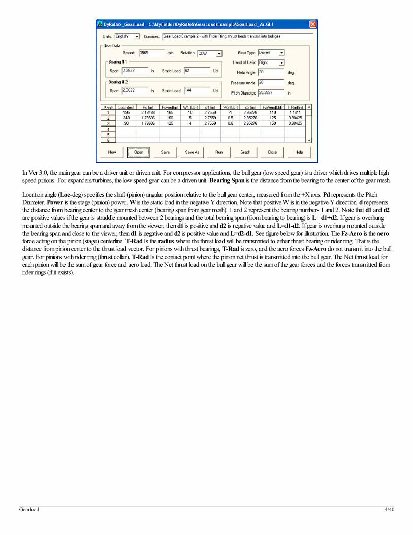
In Ver 3.0, the main gear can be a driver unit or driven unit. For compressor applications, the bull gear (low speed gear) is a driver which drives multiple highspeed pinions. For expanders/turbines, the low speed gear can be a driven unit. Bearing Span is the distance from the bearing to the center of the gear mesh.
Location angle (Loc-deg) specifies the shaft (pinion) angular position relative to the bull gear center, measured from the +X axis. Pd represents the PitchDiameter. Power is the stage (pinion) power. W is the static load in the negative Y direction. Note that positive W is in the negative Y direction. d representsthe distance from bearing center to the gear mesh center (bearing span from gear mesh). 1 and 2 represent the bearing numbers 1 and 2. Note that d1 and d2are positive values if the gear is straddle mounted between 2 bearings and the total bearing span (from bearing to bearing) is L= d1+d2. If gear is overhungmounted outside the bearing span and away from the viewer, then d1 is positive and d2 is negative value and L=d1-d2. If gear is overhung mounted outsidethe bearing span and close to the viewer, then d1 is negative and d2 is positive value and L=d2-d1. See figure below for illustration. The Fz-Aero is the aeroforce acting on the pinion (stage) centerline. T-Rad Is the radius where the thrust load will be transmitted to either thrust bearing or rider ring. That is thedistance from pinion center to the thrust load vector. For pinions with thrust bearings, T-Rad is zero, and the aero forces Fz-Aero do not transmit into the bullgear. For pinions with rider ring (thrust collar), T-Rad Is the contact point where the pinion net thrust is transmitted into the bull gear. The Net thrust load foreach pinion will be the sum of gear force and aero load. The Net thrust load on the bull gear will be the sum of the gear forces and the forces transmitted fromrider rings (if it exists).
Gearload 4/40

Outputs for the above input data can be a graphic plot of a text output. The graph is shown below. It contains the bearing load vectors (magnitudes & angles)and each shaft location with respect to the bull gear. It also contains the thrust loads for each rotor. Note that for thrust load, positive is toward the viewer.With rider ring design, the pinion thrust load is the load acting on the low speed bull gear thrust collar from the pinion. The total thrust load on the bull gear willbe the summation of these pinion thrust forces and the gear axial forces from each pinion. It will be exactly equal to the total aero loads.
Gearload 5/40
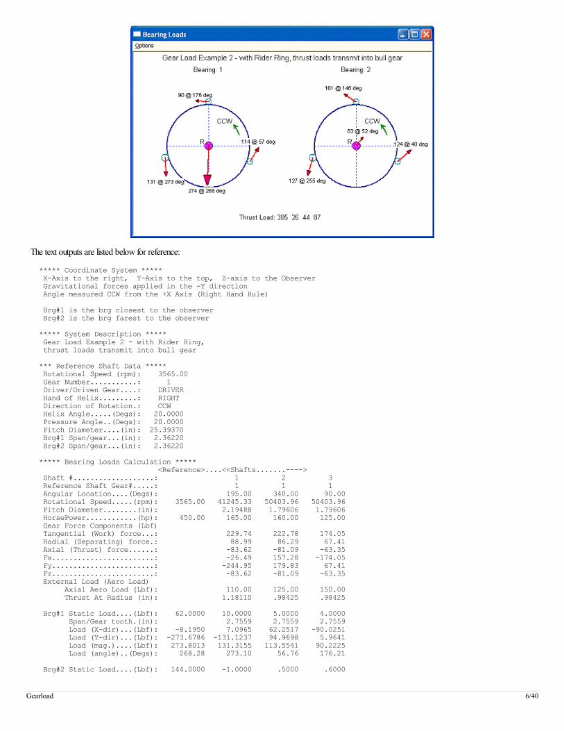
The text outputs are listed below for reference:
***** Coordinate System ***** X-Axis to the right, Y-Axis to the top, Z-axis to the Observer Gravitational forces applied in the -Y direction Angle measured CCW from the +X Axis (Right Hand Rule) Brg#1 is the brg closest to the observer Brg#2 is the brg farest to the observer ***** System Description ***** Gear Load Example 2 - with Rider Ring, thrust loads transmit into bull gear *** Reference Shaft Data ***** Rotational Speed (rpm): 3565.00 Gear Number...........: 1 Driver/Driven Gear....: DRIVER Hand of Helix.........: RIGHT Direction of Rotation.: CCW Helix Angle.....(Degs): 20.0000 Pressure Angle..(Degs): 20.0000 Pitch Diameter....(in): 25.39370 Brg#1 Span/gear...(in): 2.36220 Brg#2 Span/gear...(in): 2.36220 ***** Bearing Loads Calculation ***** <Reference>....<<Shafts.......----> Shaft #...................: 1 2 3 Reference Shaft Gear#.....: 1 1 1 Angular Location....(Degs): 195.00 340.00 90.00 Rotational Speed.....(rpm): 3565.00 41245.33 50403.96 50403.96 Pitch Diameter........(in): 2.19488 1.79606 1.79606 HorsePower............(hp): 450.00 165.00 160.00 125.00 Gear Force Components (Lbf) Tangential (Work) force...: 229.74 222.78 174.05 Radial (Separating) force.: 88.99 86.29 67.41 Axial (Thrust) force......: -83.62 -81.09 -63.35 Fx........................: -26.49 157.28 -174.05 Fy........................: -244.95 179.83 67.41 Fz........................: -83.62 -81.09 -63.35 External Load (Aero Load) Axial Aero Load (Lbf): 110.00 125.00 150.00 Thrust At Radius (in): 1.18110 .98425 .98425 Brg#1 Static Load....(Lbf): 62.0000 10.0000 5.0000 4.0000 Span/Gear tooth.(in): 2.7559 2.7559 2.7559 Load (X-dir)...(Lbf): -8.1950 7.0965 62.2517 -90.0251 Load (Y-dir)...(Lbf): -273.6786 -131.1237 94.9698 5.9641 Load (mag.)....(Lbf): 273.8013 131.3155 113.5541 90.2225 Load (angle)..(Degs): 268.28 273.10 56.76 176.21 Brg#2 Static Load....(Lbf): 144.0000 -1.0000 .5000 .6000
Gearload 6/40
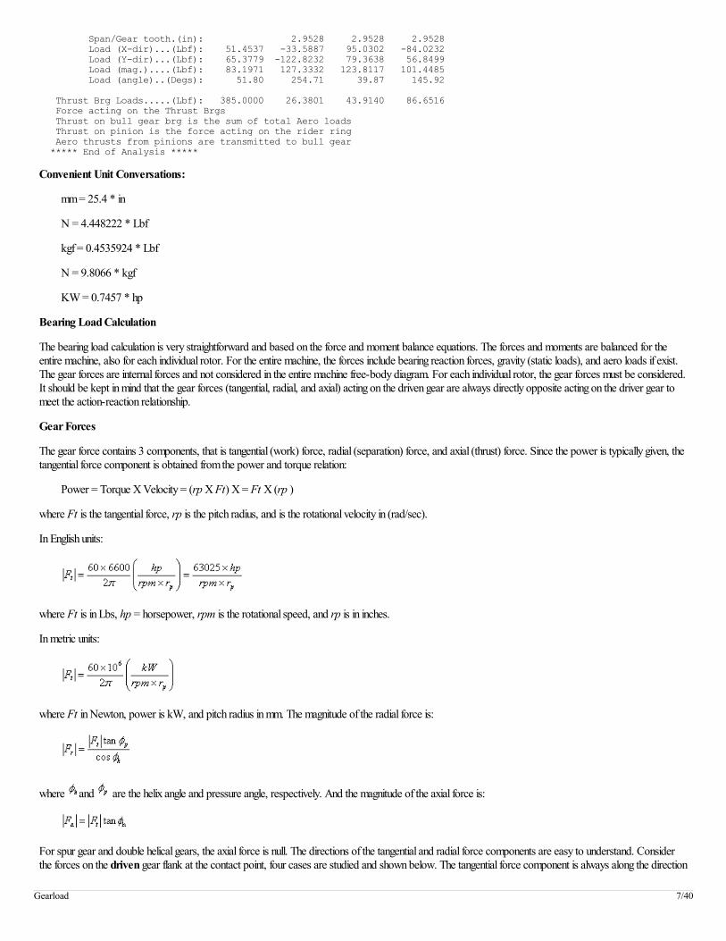
Span/Gear tooth.(in): 2.9528 2.9528 2.9528 Load (X-dir)...(Lbf): 51.4537 -33.5887 95.0302 -84.0232 Load (Y-dir)...(Lbf): 65.3779 -122.8232 79.3638 56.8499 Load (mag.)....(Lbf): 83.1971 127.3332 123.8117 101.4485 Load (angle)..(Degs): 51.80 254.71 39.87 145.92 Thrust Brg Loads.....(Lbf): 385.0000 26.3801 43.9140 86.6516 Force acting on the Thrust Brgs Thrust on bull gear brg is the sum of total Aero loads Thrust on pinion is the force acting on the rider ring Aero thrusts from pinions are transmitted to bull gear ***** End of Analysis *****
Convenient Unit Conversations:
mm = 25.4 * in
N = 4.448222 * Lbf
kgf = 0.4535924 * Lbf
N = 9.8066 * kgf
KW = 0.7457 * hp
Bearing Load Calculation
The bearing load calculation is very straightforward and based on the force and moment balance equations. The forces and moments are balanced for theentire machine, also for each individual rotor. For the entire machine, the forces include bearing reaction forces, gravity (static loads), and aero loads if exist.The gear forces are internal forces and not considered in the entire machine free-body diagram. For each individual rotor, the gear forces must be considered.It should be kept in mind that the gear forces (tangential, radial, and axial) acting on the driven gear are always directly opposite acting on the driver gear tomeet the action-reaction relationship.
Gear Forces
The gear force contains 3 components, that is tangential (work) force, radial (separation) force, and axial (thrust) force. Since the power is typically given, thetangential force component is obtained from the power and torque relation:
Power = Torque X Velocity = (rp X Ft) X = Ft X (rp )
where Ft is the tangential force, rp is the pitch radius, and is the rotational velocity in (rad/sec).
In English units:
where Ft is in Lbs, hp = horsepower, rpm is the rotational speed, and rp is in inches.
In metric units:
where Ft in Newton, power is kW, and pitch radius in mm. The magnitude of the radial force is:
where and are the helix angle and pressure angle, respectively. And the magnitude of the axial force is:
For spur gear and double helical gears, the axial force is null. The directions of the tangential and radial force components are easy to understand. Considerthe forces on the driven gear flank at the contact point, four cases are studied and shown below. The tangential force component is always along the direction
Gearload 7/40

of rotation and the radial force component is from the contact point toward the driven gear center. Without the helical angle ( ), the resulting force is
always along the pressure line ( ). Again, the forces acting on the driver gear will be exactly opposite from the force acting on the driven gear.
The magnitudes and directions of the tangential and radial forces are determined from the above discussion. It is necessary to transform the tangential andradial forces into a standard Cartesian coordinates (x, y) system for the following bearing load calculation, as shown in the figure. The transformations aregiven below:
The direction of the axial force is described in the following table when viewing from the axis of rotation.
Gearload 8/40
Hand of Helix Rotation Driver DrivenRight CCW Toward viewer (+Z) Away from viewer (-Z)Right CW Away from viewer (-Z) Toward viewer (+Z)Left CCW Away from viewer (-Z) Toward viewer (+Z)Left CW Toward viewer (+Z) Away from viewer (-Z)
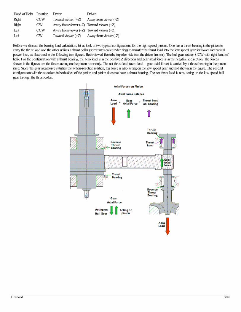
Before we discuss the bearing load calculation, let us look at two typical configurations for the high-speed pinions. One has a thrust bearing in the pinion tocarry the thrust load and the other utilizes a thrust collar (sometimes called rider ring) to transfer the thrust load into the low speed gear for lower mechanicalpower loss, as illustrated in the following two figures. Both viewed from the impeller side into the driver (motor). The bull gear rotates CCW with right hand ofhelix. For the configuration with a thrust bearing, the aero load is in the positive Z direction and gear axial force is in the negative Z direction. The forcesshown in the figures are the forces acting on the pinion rotor only. The net thrust load (aero load – gear axial force) is carried by a thrust bearing in the pinionitself. Since the gear axial force satisfies the action-reaction relation, this force is also acting on the low speed gear and not shown in the figure. The secondconfiguration with thrust collars in both sides of the pinion and pinion does not have a thrust bearing. The net thrust load is now acting on the low speed bullgear through the thrust collar.
Gearload 9/40

For the bearing load calculation, let us examine the free-body diagram of a typical pinion as shown in the following figure.
Gearload 10/40
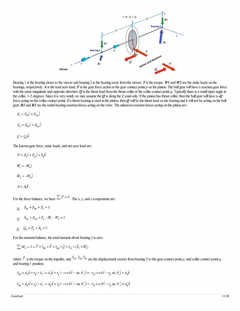
Bearing 1 is the bearing closer to the viewer and bearing 2 is the bearing away from the viewer. T is the torque. W1 and W2 are the static loads on thebearings, respectively. A is the total aero load. F is the gear force action at the gear contact point p on the pinion. The bull gear will have a reaction gear forcewith the same magnitude and opposite direction. Q is the thrust load from the thrust collar at the collar contact point q. Typically there is a small taper angle inthe collar, 1-5 degrees. Since it is very small, we may assume the Q is along the Z axial only. If the pinion has thrust collar, then the bull gear will have a -Qforce acting on the collar contact point. If a thrust bearing is used in the pinion, then Q will be the thrust load on the bearing and it will not be acting on the bullgear. R1 and R2 are the radial bearing reaction forces acting on the rotor. The unknown reaction forces acting on the pinion are:
The known gear force, static loads, and net aero load are:
For the force balance, we have . The x, y, and z components are:
X:
Y:
Z:
For the moment balance, the total moment about bearing 2 is zero.
where is the torque on the impeller, and are the displacement vectors from bearing 2 to the gear contact point p, and collar contact point q,and bearing 1 position.
Gearload 11/40
and the toque is about the axis of rotation:
where d2 is the distance measured from bearing 2 to the center of the gear mesh in the positive Z direction. Therefore, if the gear is mounted in the outside thebearing span and away from the viewer, then d2 is a negative value. dq is the distance measured from the bearing 2 to the contact point of rider ring (collar) inthe positive Z direction, it is typically equal to d2 plus or minus half of the gear face width, depending on the direction of the net thrust load. However, sincethe net thrust load is in parallel with the axis of rotation (Z axis), it will be shown later that dq is irrelevant to the calculation. rp is the pitch radius of the gearwhere the gear force F is applied and rq is the radius of the rider ring where the net thrust load Q is applied. Note if a thrust bearing is used in the pinion, thenrq =0 and no moment is generated from this net thrust load. Note that radial vector, it is because the pinion location is specified based on the bull gear.The contact point is in the negative radial direction for the pinion and positive direction for the bull gear. r21 is the distance from bearing 2 to bearing 1.Expand the moment equation, we have:
In X, Y, and Z components:
X:
Y:
Z:
From the moment about Z axis, we have the torque balance equation:
Now, we have 5 unknowns ( ) and 5 linear algebra equations ( ).
Once these 5 reactions forces are found, the bearing loads have the same magnitude and opposite directions. The radial loads can be used to determine theequilibrium position of the bearings and linearization of the bearing coefficients. The thrust load Qz is used for the thrust bearing design if a thrust bearing isused to carry this load, or is used to check the proper interference between the rider ring (thrust collars) and the pinion shaft. For the main low speed bullgear, there are multiple gear forces and thrust loads from multiple pinions. Following figure shows gear force and thrust force from one pinion. These forceshave the same magnitude with opposite directions from previous pinion forces. Also, a thrust bearing must be used in the bull gear to carry the thrust load. Tocalculate the bull gear bearing reaction forces, the equations are the same as before, except we need to sum all the gear forces and thrust forces from eachpinion also the addition of the thrust reaction force Rz from the thrust bearing.
Gearload 12/40
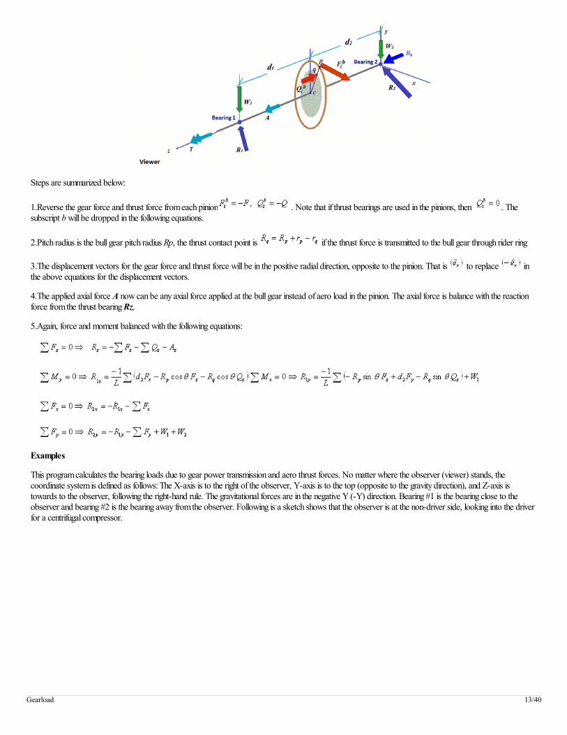
Steps are summarized below:
1.Reverse the gear force and thrust force from each pinion . Note that if thrust bearings are used in the pinions, then . Thesubscript b will be dropped in the following equations.
2.Pitch radius is the bull gear pitch radius Rp, the thrust contact point is if the thrust force is transmitted to the bull gear through rider ring
3.The displacement vectors for the gear force and thrust force will be in the positive radial direction, opposite to the pinion. That is to replace inthe above equations for the displacement vectors.
4.The applied axial force A now can be any axial force applied at the bull gear instead of aero load in the pinion. The axial force is balance with the reactionforce from the thrust bearing Rz.
5.Again, force and moment balanced with the following equations:
Examples
This program calculates the bearing loads due to gear power transmission and aero thrust forces. No matter where the observer (viewer) stands, thecoordinate system is defined as follows: The X-axis is to the right of the observer, Y-axis is to the top (opposite to the gravity direction), and Z-axis istowards to the observer, following the right-hand rule. The gravitational forces are in the negative Y (-Y) direction. Bearing #1 is the bearing close to theobserver and bearing #2 is the bearing away from the observer. Following is a sketch shows that the observer is at the non-driver side, looking into the driverfor a centrifugal compressor.
Gearload 13/40

Example 1: Static loads only
The first example used here is a very simple example and only the static loads are considered. The horsepower is zero. Then the bearing forces are due to thestatic loads only. Draw a free-body diagram for the entire machine, the force and moment must be balanced. The summation of the radial bearing reactionforces and the gravity loads should be balanced. Since in this case, there is no thrust collar (rider ring) used to transmit the thrust to the low speed gear, thethrust load in the pinion is the aero load and the bull gear has no thrust load if no power transmission.
Fig 1-1
Gearload 14/40
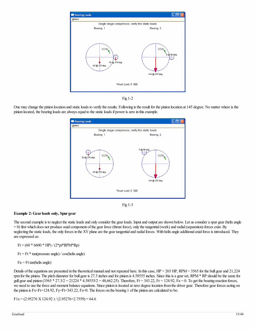
Fig 1-2
One may change the pinion location and static loads to verify the results. Following is the result for the pinion location at 145 degree. No matter where is thepinion located, the bearing loads are always equal to the static loads if power is zero in this example.
Fig 1-3
Example 2: Gear loads only, Spur gear
The second example is to neglect the static loads and only consider the gear loads. Input and output are shown below. Let us consider a spur gear (helix angle= 0) first which does not produce axial component of the gear force (thrust force), only the tangential (work) and radial (separation) forces exist. Byneglecting the static loads, the only forces in the XY plane are the gear tangential and radial forces. With helix angle additional axial force is introduced. Theyare expressed as:
Ft = (60 * 6600 * HP) / (2*pi*RPM*Rp)
Fr = Ft * tan(pressure angle) / cos(helix angle)
Fa = Ft tan(helix angle)
Details of the equations are presented in the theoretical manual and not repeated here. In this case, HP = 265 HP, RPM = 3565 for the bull gear and 21,224rpm for the pinion. The pitch diameter for bull gear is 27.3 inches and for pinion is 4.58555 inches. Since this is a gear set, RPM * RP should be the same forgull gear and pinion (3565 * 27.3/2 = 21224 * 4.58555/2 = 48,662.25). Therefore, Ft = 343.22, Fr = 124.92, Fa = 0. To get the bearing reaction forces,we need to use the force and moment balance equations. Since pinion is located at zero degree location from the driver gear. Therefore gear forces acting onthe pinion is Fx=Fr=124.92, Fy=Ft=343.22, Fz=0. The forces on the bearing 1 of the pinion are calculated to be:
F1x = (2.95276 X 124.92 ) / (2.95276+2.7559) = 64.6
Gearload 15/40

F1y = (2.95275 X 343.22) / (2.95276+2.7559) = 177.5
The magnitude of the force will be 189 at 70 degree on bearing 1 of the pinion.
The forces on the bearing 2 of the pinion are:
F2x = Fx - F1x = 60.3
F2y = Fy – F2x = 165.7
The magnitude of the force will be 176 at 70 degree on bearing 2 of the pinion.
The gear force acting on the bull gear will be the opposite of the gear force acting on the pinion. So, the forces on the bearing 1 of the bull gear are:
F1x = (2.3622 X (-124.92)) / (2.3622+2.3622) = -62.5
F1y = (2.3622 X (-343.22)) / (2.3622+2.3622) = -171.6
The forces on bearing 2 are:
F2x = -124.92 – (-62.5) = -62.5
F2y = -343.22 – (-171.6) = - 171.6
Both have the same magnitude of 183 at 250 degree. Also, the sum of all the forces is balanced (189+176-183-183 = 0). The forces are acting along thepressure line for spur gears without helix angle in this example, as illustrated in the tangential and radial forces equations. Note that bull gear is the driver gearin this example. For the bull gear bearings since the bearing span is identical, the loads are identical too for the balance of the moment. For pinion, the bearing1 has a smaller bearing span (2.7559) than that of bearing 2 (2.95276). Therefore, the load on bearing 1 (189) is larger than that of bearing 2 (176). Again,there is no axial gear force due to zero helix angle and the thrust load on the pinion is the aero load and bull gear has zero thrust load.
Fig 2-1
Gearload 16/40

Fig 2-2
Let us change the pressure angle to be 15 degree. The result is shown below. Again the forces are along the pressure line and the bull gear is the driver gear inthis example. Also, the forces on the bearings are different from previous case due to different radial gear forces from different pressure angle. However, theforce and moment are still balanced.
Fig 2-3
Next, let us change the driver unit and make the low speed gear as a driven unit and high speed pinion as the driver. Now, the forces are still acting along thepressure line, but pinion is the driver unit and bull gear is the driven unit. The magnitudes of the forces are still the same, but directions are different from case1.
Gearload 17/40
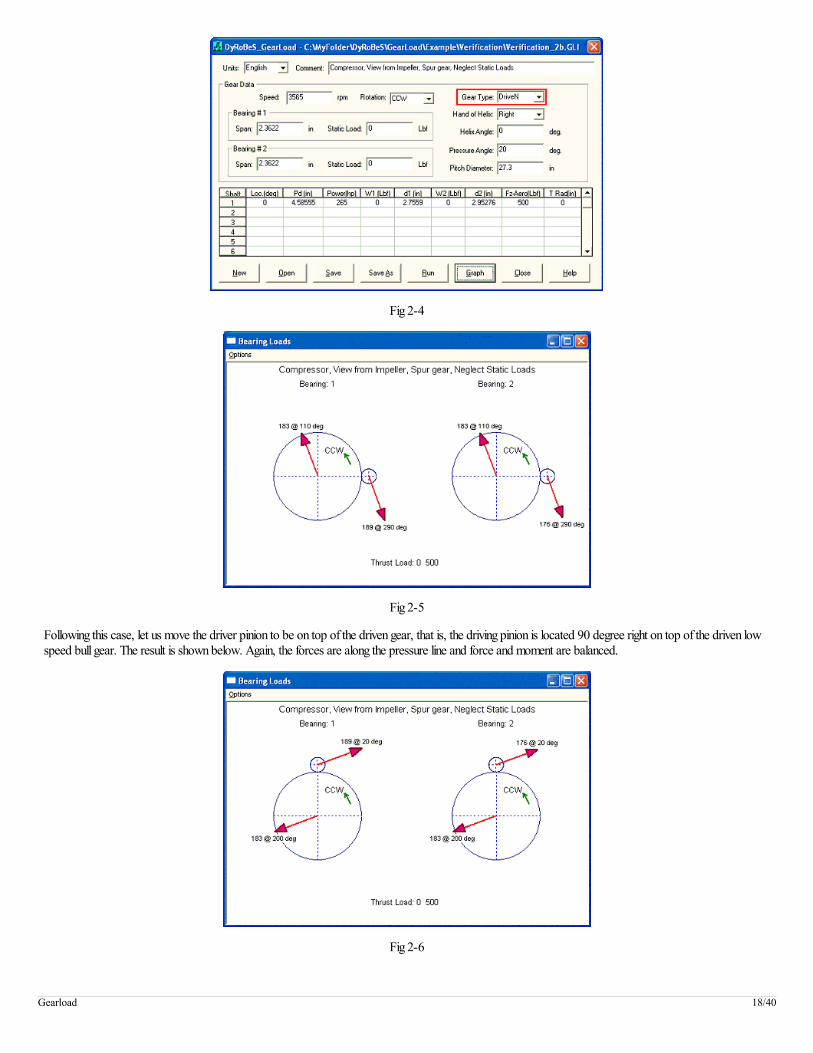
Fig 2-4
Fig 2-5
Following this case, let us move the driver pinion to be on top of the driven gear, that is, the driving pinion is located 90 degree right on top of the driven lowspeed bull gear. The result is shown below. Again, the forces are along the pressure line and force and moment are balanced.
Fig 2-6
Gearload 18/40

Next, let us move the driving pinion back to the zero degree and change the direction of rotation of the driven gear to be CW. The results are identical to Fig.2.2. That is if the low speed gear is a driver unit and rotates CCW has the same force vector as if the low speed gear is a driven unit and rotates CW.
Fig 2-7
Fig 2-8
Example 3: Gear loads only, Helical gear
Use the example in example 2 case 1 and add the helix angle of 18 degrees. When the low speed gear is the driver and rotates CCW with right hand of helix,viewed from the axis of rotation, the axial component of the gear force acting on the pinion is in the negative Z direction (away from the observer) andopposite to the aero thrust load. Therefore, the thrust load at the pinion is the aero load minus the gear axial load (500 – 112 = 388) and this load must becarried by a thrust bearing on the pinion. With the action and reaction relationship, the thrust load at the driver (bull gear) will be the axial gear load of 112which will be carried by a thrust bearing at the bull gear shaft. However, this gear axial load is acting on the pitch diameter, it produces a large moment actingon the bearing. The moment can be high if the gear pitch diameter is large. Consider the bull gear shaft, the axial load is 112 and the pitch diameter is 27.3, themoment in the (-Y) direction acting on the bearing will be (112X(27.3/2) = 1529). The magnitude of the force acting on the bearing will be the momentdivides the bearing span. For bull gear bearings, the total bearing span is (2.3622X2=4.7244), the force will be (1529/4.7244=324). Since this axial force ispositive acting on the bull gear, the additional force due to this moment acting on the bull gear bearing 1 will be 324 in the 180 degree direction (-X) and 0degree (+X) direction on the bearing 2. This effect can be seen by comparing the force diagram with the helix angle = 0 in previous example (Example 2 –case 1). For the driven pinion the pitch diameter is small, the moment due to axial load is also small. Also, with the introduction of helix angle, the gear radialforce component also changes slightly. A sketch illustrating this axial gear load effect is shown below.
Gearload 19/40

Fig 3-1
Fig 3-2
Fig 3-3
Example 4: Gear loads + Static loads, Helical gear
In the example, let us add the static loads on the bearings back. Now, the total bearing loads will be the sum of the gear forces and the static loads.
Gearload 20/40

Fig 4-1
Fig 4-2
Let us check the bearing 1 on bull gear. Without the static load, the load is 424 at 204 degree, as illustrated in Example 3. With the static load 62 at 270degree, the vector sum becomes 453 at 211 degree. For bearing 2 on the pinion, without the static load, the load is 198 at 57 degree. With the static load 5at 90 degree, the total bearing load becomes 202 at 58 degree. Same discussions are applied for other 2 bearings.
Example 5: Expander Application
Let us consider the low speed gear is a driven unit and high speed pinion is a driver unit, such as in the expander applications. First, let us consider the helixangle is zero such that the axial gear force can be eliminated and only the gear radial and tangential forces are considered with the bearing static loads.Comparing Fig. 5.2 to the Fig. 2.5, noticed that the resulting bearing load vector of Fig 5.2 has shifted towards the bearing static load. Actually, the sum of theload vectors in Fig. 2.5 and the static loads will result in the Fig. 5.2. For example, the load vector for bearing 2 of the bull gear without static load is 183 at110 degree. The static load is given as 144 at 270 degree. The resulting vector will be the vector summation and is 68 at 156 degree. Others can be verifiedin the same way.
Gearload 21/40
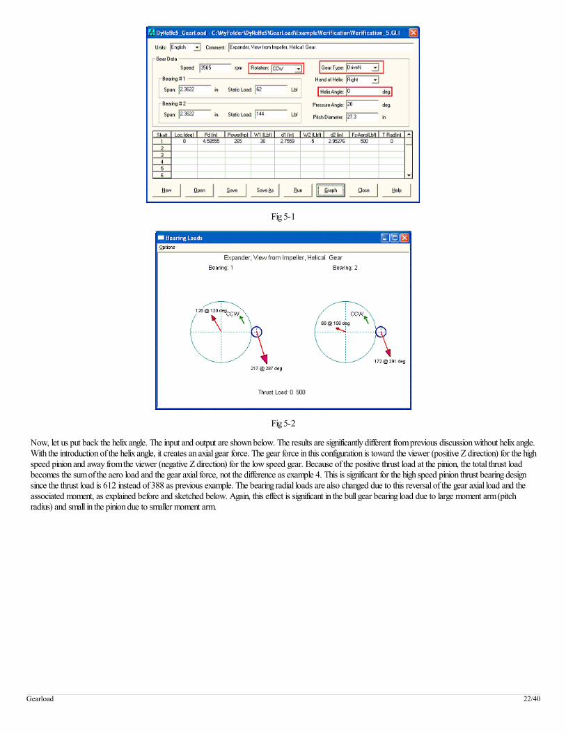
Fig 5-1
Fig 5-2
Now, let us put back the helix angle. The input and output are shown below. The results are significantly different from previous discussion without helix angle.With the introduction of the helix angle, it creates an axial gear force. The gear force in this configuration is toward the viewer (positive Z direction) for the highspeed pinion and away from the viewer (negative Z direction) for the low speed gear. Because of the positive thrust load at the pinion, the total thrust loadbecomes the sum of the aero load and the gear axial force, not the difference as example 4. This is significant for the high speed pinion thrust bearing designsince the thrust load is 612 instead of 388 as previous example. The bearing radial loads are also changed due to this reversal of the gear axial load and theassociated moment, as explained before and sketched below. Again, this effect is significant in the bull gear bearing load due to large moment arm (pitchradius) and small in the pinion due to smaller moment arm.
Gearload 22/40

Fig 5-3
Fig 5-4
Fig 5-5
In order to reduce this thrust load at the high speed pinion, let us change the rotation of direction of the low speed bull gear to be CW. The input and outputare shown below. No surprise, that the results are now identical to the Fig 4.2. That is if both the direction of rotation and driver/driven role change, then theresults are identical due to the same gear force.
Gearload 23/40
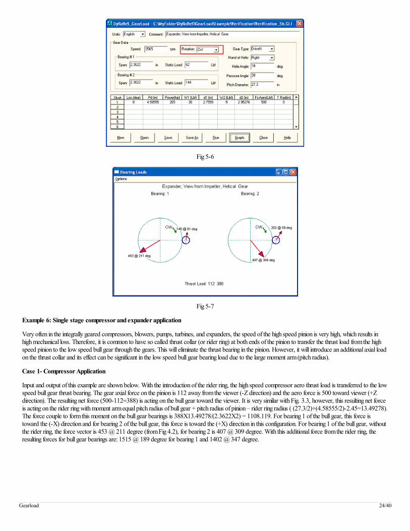
Fig 5-6
Fig 5-7
Example 6: Single stage compressor and expander application
Very often in the integrally geared compressors, blowers, pumps, turbines, and expanders, the speed of the high speed pinion is very high, which results inhigh mechanical loss. Therefore, it is common to have so called thrust collar (or rider ring) at both ends of the pinion to transfer the thrust load from the highspeed pinion to the low speed bull gear through the gears. This will eliminate the thrust bearing in the pinion. However, it will introduce an additional axial loadon the thrust collar and its effect can be significant in the low speed bull gear bearing load due to the large moment arm (pitch radius).
Case 1- Compressor Application
Input and output of this example are shown below. With the introduction of the rider ring, the high speed compressor aero thrust load is transferred to the lowspeed bull gear thrust bearing. The gear axial force on the pinion is 112 away from the viewer (-Z direction) and the aero force is 500 toward viewer (+Zdirection). The resulting net force (500-112=388) is acting on the bull gear toward the viewer. It is very similar with Fig. 3.3, however, this resulting net forceis acting on the rider ring with moment arm equal pitch radius of bull gear + pitch radius of pinion – rider ring radius ( (27.3/2)+(4.58555/2)-2.45=13.49278).The force couple to form this moment on the bull gear bearings is 388X13.49278/(2.3622X2) = 1108.119. For bearing 1 of the bull gear, this force istoward the (-X) direction and for bearing 2 of the bull gear, this force is toward the (+X) direction in this configuration. For bearing 1 of the bull gear, withoutthe rider ring, the force vector is 453 @ 211 degree (from Fig 4.2), for bearing 2 is 407 @ 309 degree. With this additional force from the rider ring, theresulting forces for bull gear bearings are: 1515 @ 189 degree for bearing 1 and 1402 @ 347 degree.
Gearload 24/40
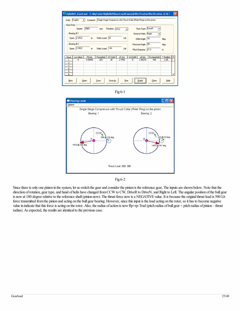
Fig 6-1
Fig 6-2
Since there is only one pinion in the system, let us switch the gear and consider the pinion is the reference gear, The inputs are shown below. Note that thedirection of rotation, gear type, and hand of helix have changed from CCW to CW, DriveR to DriveN, and Right to Left. The angular position of the bull gearis now at 180 degree relative to the reference shaft (pinion now). The thrust force now is a NEGATIVE value. It is because the original thrust load is 500 Lbforce transmitted from the pinion and acting on the bull gear bearing. However, since this input is the load acting on the rotor, so it has to become negativevalue in indicate that this force is acting on the rotor. Also, the radius of action is now Rp+rp-Trad (pitch radius of bull gear + pitch radius of pinion – thrustradius). As expected, the results are identical to the previous case.
Gearload 25/40

Fig 6-3
Fig 6-4
Case 2- Expander Application
Use this example again, however now the pinion is the driver and the bull gear becomes a driven unit. All other data are the same as before. First let us usebull gear as the reference shaft, and inputs and outputs are shown below. Note that, in this case, the gear axial force is in the same direction as the aero force,therefore, the pinion net thrust load is the sum of gear axial force and the aero force.
Gearload 26/40

Fig 6-5
Fig 6-6
Fig 6-7
Gearload 27/40

Fig 6-8
Example 7: A single stage blower with thrust bearing or thrust ring on the pinion
Case1: A single stage compressor or blower is used in this example. A motor drives a bull gear and the bull gear drives a high-speed pinion which carries animpeller. Impeller compresses air. For the high-speed pinion, a thrust bearing is used to carry the thrust load acting on the pinion. Therefore, there is no needto enter the aero thrust load for radial bearing load analysis. The viewer is in front of the impeller and looking into the driver (motor in this case). Bearing #1will be the bearing in the air side and bearing #2 will be the bearing near the motor side. The Input screen and outputs (graph and text) are shown below:
Fig 7-1
Gearload 28/40

Fig 7-2
Text Outputs:
***** Coordinate System ***** X-Axis to the right, Y-Axis to the top, Z-axis to the Observer Gravitational forces applied in the -Y direction Angle measured CCW from the +X Axis (Right Hand Rule) Brg#1 is the brg closest to the observer Brg#2 is the brg farest to the observer ***** System Description ***** Single stage compressor (blower), viewed from non-driver side ***** Reference Shaft Data ***** Rotational Speed (rpm): 3565.00 Gear Number...........: 1 Driver/Driven Gear....: DRIVER Hand of Helix.........: RIGHT Direction of Rotation.: CCW Helix Angle.....(Degs): 18.0000 Pressure Angle..(Degs): 20.0000 Pitch Diameter....(in): 27.30000 Brg#1 Span/gear...(in): 2.36220 Brg#2 Span/gear...(in): 2.36220 ***** Bearing Loads Calculation ***** <Reference>....<<Shafts.......----> Shaft #...................: 1 Reference Shaft Gear#.....: 1 Angular Location....(Degs): .00 Rotational Speed.....(rpm): 3565.00 21224.17 Pitch Diameter........(in): 4.58555 HorsePower............(hp): 265.00 265.00 Gear Force Components (Lbf) Acting on the driven shafts Tangential (Work) force...: 343.22 Radial (Separating) force.: 131.35 Axial (Thrust) force......: -111.52 External Load (Aero Load) Axial Aero Load (Lbf): .00 Thrust At Radius (in): .00000 Brg#1 Static Load....(Lbf): 62.0000 30.0000 Span/Gear tooth.(in): 2.7559 Load (X-dir)...(Lbf): -387.8788 23.1504 Load (Y-dir)...(Lbf): -233.6086 147.5264 Load (mag.)....(Lbf): 452.7946 149.3318 Load (angle)..(Degs): 211.06 81.08 Brg#2 Static Load....(Lbf): 144.0000 -5.0000 Span/Gear tooth.(in): 2.9528 Load (X-dir)...(Lbf): 256.5293 108.1991 Load (Y-dir)...(Lbf): -315.6086 170.6908 Load (mag.)....(Lbf): 406.7137 202.0950 Load (angle)..(Degs): 309.10 57.63
Gearload 29/40

Thrust Brg Loads.....(Lbf): 111.5180 -111.5180 ***** End of Analysis *****
Case 2: Now, let us view the machine from the driver (motor) side. The direction of rotation is reversed from previous input. Also, the X and Z coordinatesare reversed. The bearing #1 is now the bearing at the driver (motor) side and bearing #2 is the bearing away from the driver since the observer is in thedriver side now. The shaft angular position is also flipped horizontally from zero to 180 deg. The input and outputs are shown below. Note that since the Zaxis is reversed, the thrust loads are now also reversed.
Fig 7-3
Fig 7-4
***** Coordinate System ***** X-Axis to the right, Y-Axis to the top, Z-axis to the Observer Gravitational forces applied in the -Y direction Angle measured CCW from the +X Axis (Right Hand Rule) Brg#1 is the brg closest to the observer Brg#2 is the brg farest to the observer ***** System Description ***** Single stage compressor (blower), viewed from driver side ***** Reference Shaft Data ***** Rotational Speed (rpm): 3565.00 Gear Number...........: 1 Driver/Driven Gear....: DRIVER Hand of Helix.........: RIGHT Direction of Rotation.: CW Helix Angle.....(Degs): 18.0000 Pressure Angle..(Degs): 20.0000
Gearload 30/40

Pitch Diameter....(in): 27.30000 Brg#1 Span/gear...(in): 2.36220 Brg#2 Span/gear...(in): 2.36220 ***** Bearing Loads Calculation ***** <Reference>....<<Shafts.......----> Shaft #...................: 1 Reference Shaft Gear#.....: 1 Angular Location....(Degs): 180.00 Rotational Speed.....(rpm): 3565.00 21224.17 Pitch Diameter........(in): 4.58555 HorsePower............(hp): 265.00 265.00 Gear Force Components (Lbf) Acting on the driven shafts Tangential (Work) force...: 343.22 Radial (Separating) force.: 131.35 Axial (Thrust) force......: -111.52 External Load (Aero Load) Axial Aero Load (Lbf): .00 Thrust At Radius (in): .00000 Brg#1 Static Load....(Lbf): 144.0000 -5.0000 Span/Gear tooth.(in): 2.9528 Load (X-dir)...(Lbf): -256.5293 -108.1991 Load (Y-dir)...(Lbf): -315.6086 170.6908 Load (mag.)....(Lbf): 406.7137 202.0950 Load (angle)..(Degs): 230.90 122.37 Brg#2 Static Load....(Lbf): 62.0000 30.0000 Span/Gear tooth.(in): 2.7559 Load (X-dir)...(Lbf): 387.8788 -23.1504 Load (Y-dir)...(Lbf): -233.6086 147.5264 Load (mag.)....(Lbf): 452.7946 149.3318 Load (angle)..(Degs): 328.94 98.92 Thrust Brg Loads.....(Lbf): -111.5180 111.5180 ***** End of Analysis *****
In the Ver 3.0, the graph can be viewed from the opposite side. For example, in this above case, although our analysis was performed as viewer in the driverside, the bearing loads can be graphed from the opposite side, that is viewed from the air side as the first case.
Fig 7-5
This also illustrates that no matter where the observer (viewer) is, the bearing loads are identical. Since in the above cases, the aero thrust load was notsupplied in the input, the thrust loads due to helical gear force on low-speed bull gear and high-speed pinion are identical in magnitude and opposite in sign.Without helical angle, the axial gear force will be null.
Case 3: Now, let us add aero thrust load on the pinion as shown below. A thrust bearing is used in the pinion to carry the thrust load. Therefore, the thrustload from high speed pinion is not transmitted to the low speed bull gear. The thrust collar radius is entered as zero for thrust bearing application. The resultsshow that the radial bearing loads and associated angles are not affected by this aero thrust load if a thrust bearing is used in the high speed pinion. Asexpected, the only difference is the thrust load on the high-speed pinion. The resulting thrust load on the pinion is the sum of aero load and gear axial force thata thrust bearing must be abale to carry this net thrust load. The thrust load on the gull gear is the same as before.
Gearload 31/40
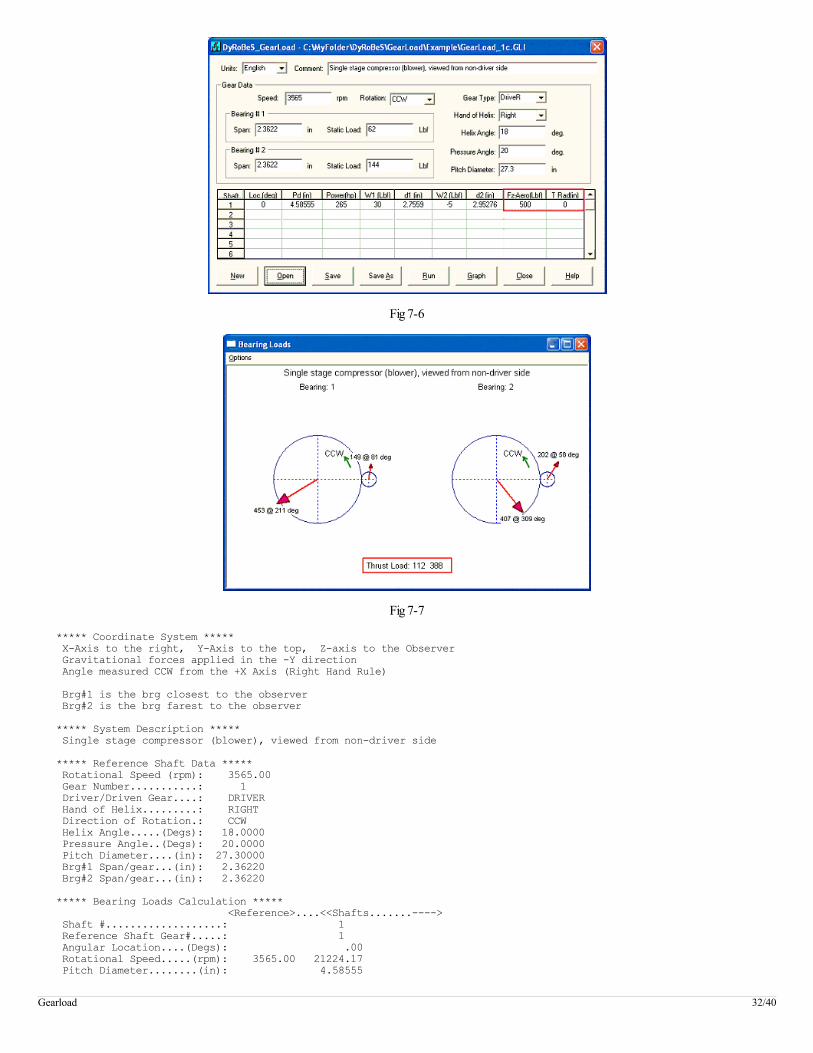
Fig 7-6
Fig 7-7
***** Coordinate System ***** X-Axis to the right, Y-Axis to the top, Z-axis to the Observer Gravitational forces applied in the -Y direction Angle measured CCW from the +X Axis (Right Hand Rule) Brg#1 is the brg closest to the observer Brg#2 is the brg farest to the observer ***** System Description ***** Single stage compressor (blower), viewed from non-driver side ***** Reference Shaft Data ***** Rotational Speed (rpm): 3565.00 Gear Number...........: 1 Driver/Driven Gear....: DRIVER Hand of Helix.........: RIGHT Direction of Rotation.: CCW Helix Angle.....(Degs): 18.0000 Pressure Angle..(Degs): 20.0000 Pitch Diameter....(in): 27.30000 Brg#1 Span/gear...(in): 2.36220 Brg#2 Span/gear...(in): 2.36220 ***** Bearing Loads Calculation ***** <Reference>....<<Shafts.......----> Shaft #...................: 1 Reference Shaft Gear#.....: 1 Angular Location....(Degs): .00 Rotational Speed.....(rpm): 3565.00 21224.17 Pitch Diameter........(in): 4.58555
Gearload 32/40
HorsePower............(hp): 265.00 265.00 Gear Force Components (Lbf) Tangential (Work) force...: 343.22 Radial (Separating) force.: 131.35 Axial (Thrust) force......: -111.52 External Load (Aero Load) Axial Aero Load (Lbf): 500.00 Thrust At Radius (in): .00000 Brg#1 Static Load....(Lbf): 62.0000 30.0000 Span/Gear tooth.(in): 2.7559 Load (X-dir)...(Lbf): -387.8788 23.1504 Load (Y-dir)...(Lbf): -233.6086 147.5264 Load (mag.)....(Lbf): 452.7946 149.3318 Load (angle)..(Degs): 211.06 81.08 Brg#2 Static Load....(Lbf): 144.0000 -5.0000 Span/Gear tooth.(in): 2.9528 Load (X-dir)...(Lbf): 256.5293 108.1991 Load (Y-dir)...(Lbf): -315.6086 170.6908 Load (mag.)....(Lbf): 406.7137 202.0950 Load (angle)..(Degs): 309.10 57.63 Thrust Brg Loads.....(Lbf): 111.5180 388.4820 Force acting on the Thrust Brgs Each rotor has its own thrust bearing ***** End of Analysis *****
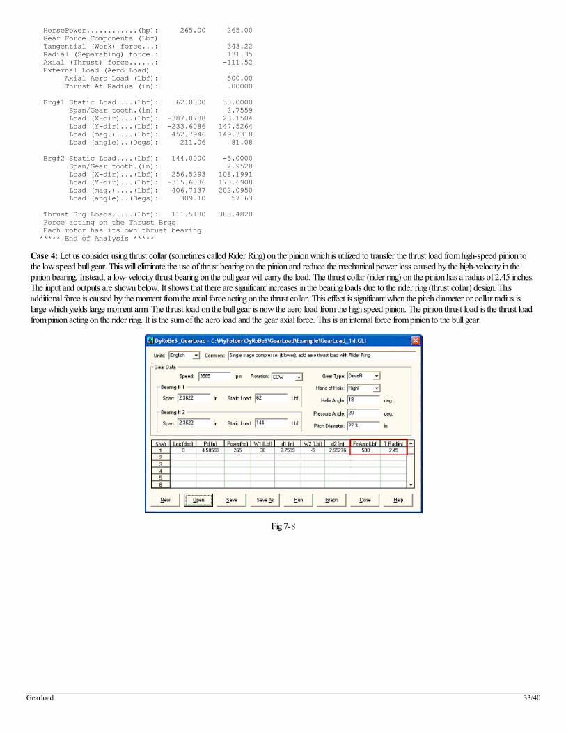
Case 4: Let us consider using thrust collar (sometimes called Rider Ring) on the pinion which is utilized to transfer the thrust load from high-speed pinion tothe low speed bull gear. This will eliminate the use of thrust bearing on the pinion and reduce the mechanical power loss caused by the high-velocity in thepinion bearing. Instead, a low-velocity thrust bearing on the bull gear will carry the load. The thrust collar (rider ring) on the pinion has a radius of 2.45 inches.The input and outputs are shown below. It shows that there are significant increases in the bearing loads due to the rider ring (thrust collar) design. Thisadditional force is caused by the moment from the axial force acting on the thrust collar. This effect is significant when the pitch diameter or collar radius islarge which yields large moment arm. The thrust load on the bull gear is now the aero load from the high speed pinion. The pinion thrust load is the thrust loadfrom pinion acting on the rider ring. It is the sum of the aero load and the gear axial force. This is an internal force from pinion to the bull gear.
Fig 7-8
Gearload 33/40

Fig 7-9
***** Coordinate System ***** X-Axis to the right, Y-Axis to the top, Z-axis to the Observer Gravitational forces applied in the -Y direction Angle measured CCW from the +X Axis (Right Hand Rule) Brg#1 is the brg closest to the observer Brg#2 is the brg farest to the observer ***** System Description ***** Single stage compressor (blower), add aero thrust load with Rider Ring ***** Reference Shaft Data ***** Rotational Speed (rpm): 3565.00 Gear Number...........: 1 Driver/Driven Gear....: DRIVER Hand of Helix.........: RIGHT Direction of Rotation.: CCW Helix Angle.....(Degs): 18.0000 Pressure Angle..(Degs): 20.0000 Pitch Diameter....(in): 27.30000 Brg#1 Span/gear...(in): 2.36220 Brg#2 Span/gear...(in): 2.36220 ***** Bearing Loads Calculation ***** <Reference>....<<Shafts.......----> Shaft #...................: 1 Reference Shaft Gear#.....: 1 Angular Location....(Degs): .00 Rotational Speed.....(rpm): 3565.00 21224.17 Pitch Diameter........(in): 4.58555 HorsePower............(hp): 265.00 265.00 Gear Force Components (Lbf) Acting on the driven shafts Tangential (Work) force...: 343.22 Radial (Separating) force.: 131.35 Axial (Thrust) force......: -111.52 External Load (Aero Load) Axial Aero Load (Lbf): 500.00 Thrust At Radius (in): 2.45000 Brg#1 Static Load....(Lbf): 62.0000 30.0000 Span/Gear tooth.(in): 2.7559 Load (X-dir)...(Lbf): -1497.3742 -143.5754 Load (Y-dir)...(Lbf): -233.6086 147.5264 Load (mag.)....(Lbf): 1515.4876 205.8590 Load (angle)..(Degs): 188.87 134.22 Brg#2 Static Load....(Lbf): 144.0000 -5.0000 Span/Gear tooth.(in): 2.9528 Load (X-dir)...(Lbf): 1366.0247 274.9249 Load (Y-dir)...(Lbf): -315.6086 170.6908 Load (mag.)....(Lbf): 1402.0101 323.6032 Load (angle)..(Degs): 346.99 31.83 Thrust Brg Loads.....(Lbf): 500.0000 388.4820
Gearload 34/40
Force acting on the Thrust Brgs Thrust on bull gear brg is the sum of total Aero loads Thrust on pinion is the force acting on the rider ring Aero thrusts from pinions are transmitted to bull gear ***** End of Analysis *****
Example 8: A 3-stages compressors
In this example, a 3-stages compressor is used to illustrate the use of this program.
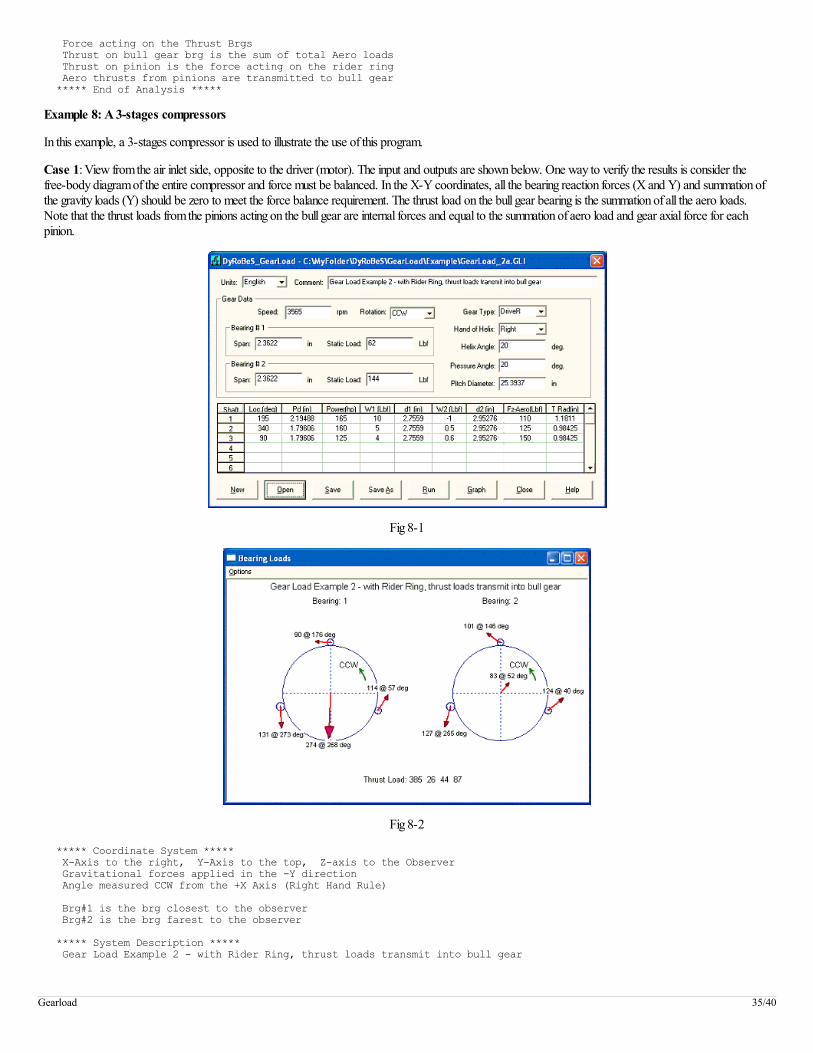
Case 1: View from the air inlet side, opposite to the driver (motor). The input and outputs are shown below. One way to verify the results is consider thefree-body diagram of the entire compressor and force must be balanced. In the X-Y coordinates, all the bearing reaction forces (X and Y) and summation ofthe gravity loads (Y) should be zero to meet the force balance requirement. The thrust load on the bull gear bearing is the summation of all the aero loads.Note that the thrust loads from the pinions acting on the bull gear are internal forces and equal to the summation of aero load and gear axial force for eachpinion.
Fig 8-1
Fig 8-2
***** Coordinate System ***** X-Axis to the right, Y-Axis to the top, Z-axis to the Observer Gravitational forces applied in the -Y direction Angle measured CCW from the +X Axis (Right Hand Rule) Brg#1 is the brg closest to the observer Brg#2 is the brg farest to the observer ***** System Description ***** Gear Load Example 2 - with Rider Ring, thrust loads transmit into bull gear
Gearload 35/40

***** Reference Shaft Data ***** Rotational Speed (rpm): 3565.00 Gear Number...........: 1 Driver/Driven Gear....: DRIVER Hand of Helix.........: RIGHT Direction of Rotation.: CCW Helix Angle.....(Degs): 20.0000 Pressure Angle..(Degs): 20.0000 Pitch Diameter....(in): 25.39370 Brg#1 Span/gear...(in): 2.36220 Brg#2 Span/gear...(in): 2.36220 ***** Bearing Loads Calculation ***** <Reference>....<<Shafts.......----> Shaft #...................: 1 2 3 Reference Shaft Gear#.....: 1 1 1 Angular Location....(Degs): 195.00 340.00 90.00 Rotational Speed.....(rpm): 3565.00 41245.33 50403.96 50403.96 Pitch Diameter........(in): 2.19488 1.79606 1.79606 HorsePower............(hp): 450.00 165.00 160.00 125.00 Gear Force Components (Lbf) Acting on the driven shafts Tangential (Work) force...: 229.74 222.78 174.05 Radial (Separating) force.: 88.99 86.29 67.41 Axial (Thrust) force......: -83.62 -81.09 -63.35 External Load (Aero Load) Axial Aero Load (Lbf): 110.00 125.00 150.00 Thrust At Radius (in): 1.18110 .98425 .98425 Brg#1 Static Load....(Lbf): 62.0000 10.0000 5.0000 4.0000 Span/Gear tooth.(in): 2.7559 2.7559 2.7559 Load (X-dir)...(Lbf): -8.1950 7.0965 62.2517 -90.0251 Load (Y-dir)...(Lbf): -273.6786 -131.1237 94.9698 5.9641 Load (mag.)....(Lbf): 273.8013 131.3155 113.5541 90.2225 Load (angle)..(Degs): 268.28 273.10 56.76 176.21 Brg#2 Static Load....(Lbf): 144.0000 -1.0000 .5000 .6000 Span/Gear tooth.(in): 2.9528 2.9528 2.9528 Load (X-dir)...(Lbf): 51.4537 -33.5887 95.0302 -84.0232 Load (Y-dir)...(Lbf): 65.3779 -122.8232 79.3638 56.8499 Load (mag.)....(Lbf): 83.1971 127.3332 123.8117 101.4485 Load (angle)..(Degs): 51.80 254.71 39.87 145.92 Thrust Brg Loads.....(Lbf): 385.0000 26.3801 43.9140 86.6516 Force acting on the Thrust Brgs Thrust on bull gear brg is the sum of total Aero loads Thrust on pinion is the force acting on the rider ring Aero thrusts from pinions are transmitted to bull gear ***** End of Analysis *****
Case 2: View from the driver side (motor side). The input and outputs are shown below. Note that the bearing #1 is at the motor end and bearing #2 is at theair end now. The aero loads become negative (-Z direction). The results are identical to Case 1 as expected.
Fig 8-3
Gearload 36/40

Fig 8-4
Following graph is viewed from the air side.
Fig 8-5
***** Coordinate System ***** X-Axis to the right, Y-Axis to the top, Z-axis to the Observer Gravitational forces applied in the -Y direction Angle measured CCW from the +X Axis (Right Hand Rule) Brg#1 is the brg closest to the observer Brg#2 is the brg farest to the observer ***** System Description ***** Gear Load Example 2 - View from Motor Side ***** Reference Shaft Data ***** Rotational Speed (rpm): 3565.00 Gear Number...........: 1 Driver/Driven Gear....: DRIVER Hand of Helix.........: RIGHT Direction of Rotation.: CW Helix Angle.....(Degs): 20.0000 Pressure Angle..(Degs): 20.0000 Pitch Diameter....(in): 25.39370 Brg#1 Span/gear...(in): 2.36220 Brg#2 Span/gear...(in): 2.36220 ***** Bearing Loads Calculation ***** <Reference>....<<Shafts.......---->
Gearload 37/40
Shaft #...................: 1 2 3 Reference Shaft Gear#.....: 1 1 1 Angular Location....(Degs): 345.00 200.00 90.00 Rotational Speed.....(rpm): 3565.00 41245.33 50403.96 50403.96 Pitch Diameter........(in): 2.19488 1.79606 1.79606 HorsePower............(hp): 450.00 165.00 160.00 125.00 Gear Force Components (Lbf) Acting on the driven shafts Tangential (Work) force...: 229.74 222.78 174.05 Radial (Separating) force.: 88.99 86.29 67.41 Axial (Thrust) force......: -83.62 -81.09 -63.35 External Load (Aero Load) Axial Aero Load (Lbf): -110.00 -125.00 -150.00 Thrust At Radius (in): 1.18110 .98425 .98425 Brg#1 Static Load....(Lbf): 144.0000 -1.0000 .5000 .6000 Span/Gear tooth.(in): 2.9528 2.9528 2.9528 Load (X-dir)...(Lbf): -51.4537 33.5887 -95.0302 84.0232 Load (Y-dir)...(Lbf): 65.3779 -122.8232 79.3638 56.8499 Load (mag.)....(Lbf): 83.1971 127.3332 123.8117 101.4485 Load (angle)..(Degs): 128.20 285.29 140.13 34.08 Brg#2 Static Load....(Lbf): 62.0000 10.0000 5.0000 4.0000 Span/Gear tooth.(in): 2.7559 2.7559 2.7559 Load (X-dir)...(Lbf): 8.1950 -7.0965 -62.2517 90.0251 Load (Y-dir)...(Lbf): -273.6786 -131.1237 94.9698 5.9641 Load (mag.)....(Lbf): 273.8013 131.3155 113.5541 90.2225 Load (angle)..(Degs): 271.72 266.90 123.24 3.79 Thrust Brg Loads.....(Lbf): -385.0000 -26.3801 -43.9140 -86.6516 Force acting on the Thrust Brgs Thrust on bull gear brg is the sum of total Aero loads Thrust on pinion is the force acting on the rider ring Aero thrusts from pinions are transmitted to bull gear ***** End of Analysis *****
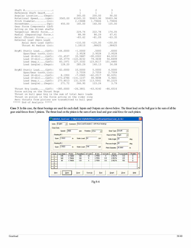
Case 3: In this case, the thrust bearings are used for each shaft. Inputs and Outputs are shown below. The thrust load on the bull gear is the sum of all thegear axial forces from 3 pinions. The thrust load on the pinion is the sum of aero load and gear axial force for each pinion.
Fig 8-6
Gearload 38/40
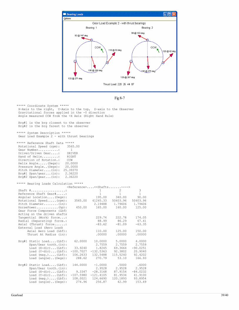
Fig 8-7
***** Coordinate System ***** X-Axis to the right, Y-Axis to the top, Z-axis to the Observer Gravitational forces applied in the -Y direction Angle measured CCW from the +X Axis (Right Hand Rule) Brg#1 is the brg closest to the observer Brg#2 is the brg farest to the observer ***** System Description ***** Gear Load Example 2 - with thrust bearings ***** Reference Shaft Data ***** Rotational Speed (rpm): 3565.00 Gear Number...........: 1 Driver/Driven Gear....: DRIVER Hand of Helix.........: RIGHT Direction of Rotation.: CCW Helix Angle.....(Degs): 20.0000 Pressure Angle..(Degs): 20.0000 Pitch Diameter....(in): 25.39370 Brg#1 Span/gear...(in): 2.36220 Brg#2 Span/gear...(in): 2.36220 ***** Bearing Loads Calculation ***** <Reference>....<<Shafts.......----> Shaft #...................: 1 2 3 Reference Shaft Gear#.....: 1 1 1 Angular Location....(Degs): 195.00 340.00 90.00 Rotational Speed.....(rpm): 3565.00 41245.33 50403.96 50403.96 Pitch Diameter........(in): 2.19488 1.79606 1.79606 HorsePower............(hp): 450.00 165.00 160.00 125.00 Gear Force Components (Lbf) Acting on the driven shafts Tangential (Work) force...: 229.74 222.78 174.05 Radial (Separating) force.: 88.99 86.29 67.41 Axial (Thrust) force......: -83.62 -81.09 -63.35 External Load (Aero Load) Axial Aero Load (Lbf): 110.00 125.00 150.00 Thrust At Radius (in): .00000 .00000 .00000 Brg#1 Static Load....(Lbf): 62.0000 10.0000 5.0000 4.0000 Span/Gear tooth.(in): 2.7559 2.7559 2.7559 Load (X-dir)...(Lbf): 33.9240 1.8245 69.3664 -90.0251 Load (Y-dir)...(Lbf): -100.7027 -132.5363 92.3802 20.9040 Load (mag.)....(Lbf): 106.2633 132.5488 115.5240 92.4202 Load (angle)..(Degs): 288.62 270.79 53.10 166.93 Brg#2 Static Load....(Lbf): 144.0000 -1.0000 .5000 .6000 Span/Gear tooth.(in): 2.9528 2.9528 2.9528 Load (X-dir)...(Lbf): 9.3347 -28.3168 87.9154 -84.0232 Load (Y-dir)...(Lbf): -107.5980 -121.4105 81.9534 41.9100 Load (mag.)....(Lbf): 108.0021 124.6690 120.1893 93.8954 Load (angle)..(Degs): 274.96 256.87 42.99 153.49
Gearload 39/40
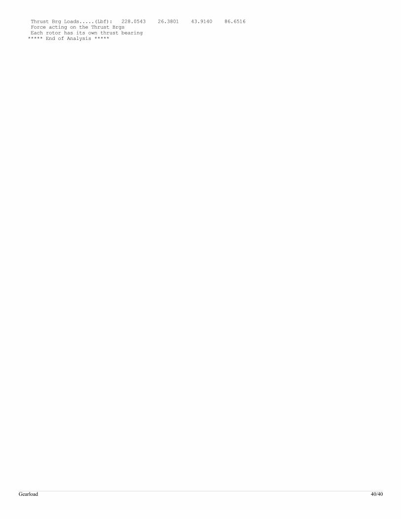
Thrust Brg Loads.....(Lbf): 228.0543 26.3801 43.9140 86.6516 Force acting on the Thrust Brgs Each rotor has its own thrust bearing ***** End of Analysis *****
Gearload 40/40