dynamics of balls and liquid in a ball mill
TRANSCRIPT

Dynamics of Balls and Liquid in a
Ball Mill
— MODELING SEMINAR SUMMER TERM 2000 —
Group members:
NGA Karunatilake
Peter Kuhn
Iuliana Matei
Jayantha Munasinghe
Benjamin Seibold
Surajiyono
Peng Thang
Supervisor:
Prof. Dr. Willy Dorfler
University of Kaiserslautern
Department of Mathematics
P.O. Box 3049
67653 Kaiserslautern

Abstract
We consider a cylindric ball mill, filled with small hardmetal balls and a suspension. Byrotating the cylinder around its main-axis the suspension shall be mixed by the balls,which are lifted up on one side and then roll or fall back onto their own surface. Thelifting is increased by nine steel bars along the cylinder wall. The problem is that theballs must not have too high velocities when they hit their surface, because they canbe damaged or even broken. Therefore it is necessary to describe the movement andthe surface structure of the balls under the influence of the suspension. We model thedynamics inside the ball mill in dependence of the filling volumes of suspension and ballsby first considering only balls without suspension and then modeling the suspensions’influence. From this we get estimates for the energy of balls hitting their surface, whichis an important value for the company.

Contents
1 Introduction 2
1.1 Mixing process in a rotating ball mill - an overview . . . . . . . . . . . . 21.2 An impression about the important effects . . . . . . . . . . . . . . . . . 51.3 Considering the problem . . . . . . . . . . . . . . . . . . . . . . . . . . . 6
2 Dry Milling 7
2.1 Basic ideas and assumptions . . . . . . . . . . . . . . . . . . . . . . . . . 72.2 Movement of the balls . . . . . . . . . . . . . . . . . . . . . . . . . . . . 82.3 Surface structure of the ball filling . . . . . . . . . . . . . . . . . . . . . . 132.4 Combining the results of Section 2.2 and 2.3 . . . . . . . . . . . . . . . . 152.5 Results, conclusions and restrictions . . . . . . . . . . . . . . . . . . . . . 16
3 Wet Milling with Liquid at Rest 18
3.1 Basic ideas and assumption . . . . . . . . . . . . . . . . . . . . . . . . . 183.2 Movement of balls . . . . . . . . . . . . . . . . . . . . . . . . . . . . . . . 193.3 Surface structure of the balls . . . . . . . . . . . . . . . . . . . . . . . . . 213.4 Result and conclusion . . . . . . . . . . . . . . . . . . . . . . . . . . . . . 22
4 Wet Milling with Moving Liquid 24
4.1 The velocity field of the suspension . . . . . . . . . . . . . . . . . . . . . 244.2 The balls’ movement under the suspensions’ influence . . . . . . . . . . . 28
5 Conclusions and Outlook 30
5.1 Comparing the three models . . . . . . . . . . . . . . . . . . . . . . . . . 305.2 Conclusions and results . . . . . . . . . . . . . . . . . . . . . . . . . . . . 335.3 Parameter discussion . . . . . . . . . . . . . . . . . . . . . . . . . . . . . 345.4 Outlook . . . . . . . . . . . . . . . . . . . . . . . . . . . . . . . . . . . . 35
1

Chapter 1
Introduction
1.1 Mixing process in a rotating ball mill - an overview
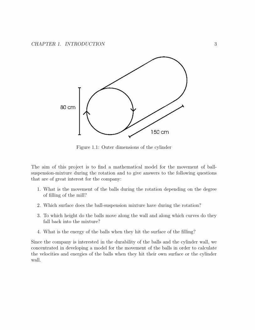
United Hardmetal GmbH is a subsidiary of the international Cerametal Group, Lux-embourg. The company is an important supplier for cemented carbide products1. Asa stage in the technological process 2, mixing of the metal carbide (tungsten-carbide)with the binder material (cobalt) takes place in a so-called “ballmill”. In this case it isa rotating cylinder at 150 cm length and 80 cm diameter shown in Figure 1.1, havingthe wall covered with liners with 1 cm height and 1.5 cm width and the length of thecylinder.The ballmill is filled with:
• hardmetal balls of 12 mm diameter, having a density of 14.5 g/cm3, and a totalmass of approximately 3000 kg (≈ 230000 balls)
• grinding suspension (tungsten-carbide (WC), cobalt, paraffin, alcohol) of density2 g cm−3, of volume between 300 l and 400 l.
Rotating the cylinder with 22 rpm, the balls are lifted up on left side with the influenceof the steel bars, which prevent the balls from sliding down the cylinder wall, and thenfall down into their own surface, helping to mix the material.
1Cemented carbides are produced by mixing various metal carbides such as tungsten carbide, tan-talum carbide, vanadium carbide, niobium carbide, chromium carbide, molybdenum carbide and/ortungsten/titanium carbide with a binder material which is usually cobalt but can be nickel or a com-bination of nickel and cobalt. The binder is added as a percentage by weight varying from 3% to 30%.The amount of binder used is a very important factor in determining the properties of each grade. Asa rule of thumbs the lower the cobalt content the harder the material will become. However variationin grain size and additives can upset this rule.
2This mixture is generally held together by some type of organic binder and formed into a desiredshape. After the forming operation, the material is sintered in a furnace. The sintering process meltsthe binder material around the carbide particles. In the process of sintering, the material shrinksvolumetrically about 43%. After sintering, the material is generally ground to the final dimensionsbefore being placed into service.
2
CHAPTER 1. INTRODUCTION 3
Figure 1.1: Outer dimensions of the cylinder
The aim of this project is to find a mathematical model for the movement of ball-suspension-mixture during the rotation and to give answers to the following questionsthat are of great interest for the company:
1. What is the movement of the balls during the rotation depending on the degreeof filling of the mill?
2. Which surface does the ball-suspension mixture have during the rotation?
3. To which height do the balls move along the wall and along which curves do theyfall back into the mixture?
4. What is the energy of the balls when they hit the surface of the filling?
Since the company is interested in the durability of the balls and the cylinder wall, weconcentrated in developing a model for the movement of the balls in order to calculatethe velocities and energies of the balls when they hit their own surface or the cylinderwall.

CHAPTER 1. INTRODUCTION 4
From literature we know three different types of movement in the ball mill during rota-tion:
a) Slow Rotation (“Cascading”, Figure 1.2):
(a) the balls are not lifted up very high
(b) they roll from each other
(c) they do not fly around
Figure 1.2: Cascading
b) Fast Rotation (“Cataracting”, Figure 1.3):
(a) the balls are lifted up very high
(b) they lose contact with the cylinder wall
(c) they fall back in parabola-like trajectories
Figure 1.3: Cataracting

CHAPTER 1. INTRODUCTION 5
c) Very Fast Rotation (”Centrifugation”, Figure 1.4):
(a) the balls are lifted up
(b) they do not lose contact with the cylinder wall (the centrifugal force is biggerthan the gravitational force)
Figure 1.4: Centrifugation
1.2 An impression about the important effects
As a first glance to the problem we compute the filling heights of the mill with onlyballs (dry milling), and balls with suspension for two different cases: 300 l and 400 l ofsuspension and a packing of the balls of 75% (25% free space between the balls). Thesefilling heights are plotted in Figure 1.5 where h1 is the filling height with only balls andh2 and h3 are the filling heights with balls and 300 l and 400 l respectively.For the general case of movement of balls in suspension, we estimate the forces actingon a ball:
Gravitational force: FG ≈ 13 cN (determined exactly by the mass of a ball and thegravitational constant)
Centrifugal force: FC ≈ 2.3 cN (depends on the distance from the middle of the cylin-der, the value taken here is for the outermost layer and by this it is an upper bound)
Buoyancy force: FA ≈ 1.8 cN (determined exactly by the volume of suspension re-placed by a ball)
Stokes’ force: FS ≈ 1.9 cN (depends on the velocity of a ball, the value taken here isfor the balls in the outermost layer and by this it is again an upper bound)

CHAPTER 1. INTRODUCTION 6
Figure 1.5: Filling heights (h1 ≈ 32 cm, h2 ≈ 51 cm, h3 ≈ 60 cm)
Considering all these facts, we can conclude that none of these forces can be neglected,so, in all our further models we take all of them into account.
1.3 Considering the problem
In order to answer the questions posed by the company, we first modeled the movementof balls in the ball mill without influence of suspension (“dry milling”). In our secondmodel we calculated the movement of balls in the resting suspension. In the third modelwe considered the movement of suspension alone in order to calculate the velocity fieldof the suspension. We then computed the movement of the balls under the influence ofthe moving suspension.Even if the rotation speed of the company’s ball mill is considered to be fixed, we con-sider in developing our model the rotation speed as a parameter, as well as volume ofsuspension and the number of balls.

Chapter 2
Dry Milling
2.1 Basic ideas and assumptions
In this section we introduce the first model. This is called dry milling because weconsider only the movement of hardmetal balls in the cylinder and neglect the influenceof the suspension. By this we only have to consider two forces, namely the gravitationalforce and the centrifugal force. By that we can easier describe the movement of theballs. For simplification we introduce further assumptions:
1. We use a two dimensional model with balls as equal-sized discs and the fillingheight calculated from the three dimensional model. This is reasonable becausewe have nearly the same filling height everywhere in the cylinder and the movementof the balls is mainly in the direction of the rotation of the mill and not in thedirection of the main axis.
2. We consider a perfect layer structure. This means that the balls are lifted up inlayers with distance of twice the radius of a ball and with the angular velocity ofthe mill. We can do so because the first layer is lifted up by the steel bars withthe angular velocity of the cylinder and the other layers are pressed to the outerlayers and so they cannot slide down and are taken with them. This structure isshown in Figure 2.1 for five layers.
3. For the calculation of the surface structure we consider a “steady state” whichmeans that the balls are moving but their surface structure does not change.
4. We neglect the rotation of the balls itself.
7

CHAPTER 2. DRY MILLING 8
Figure 2.1: Perfect layer structure
2.2 Movement of the balls
In this section we calculate the movement of the balls which are lifted up by the steelbars. Because of these steel bars we can assume that there is no slip between thehardmetal balls and the cylinder wall. We consider the forces acting on one ball in thefirst layer (see Figure 2.2):
Figure 2.2: Forces acting on a ball
FC = m(R − r)ω2 is the centrifugal force andFg = mg is the gravitational force
CHAPTER 2. DRY MILLING 9
with
m = mass of one hardmetal ball = 13.12 g,R = radius of the cylinder = 0.4 m,r = radius of a ball = 0.006 m,ω = angular velocity = 2π · 22
60s−1,
g = gravitational constant = 9.81 ms−2.
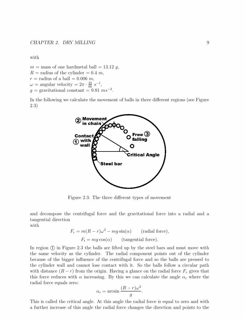
In the following we calculate the movement of balls in three different regions (see Figure2.3)
Figure 2.3: The three different types of movement
and decompose the centrifugal force and the gravitational force into a radial and atangential directionwith
Fr = m(R − r)ω2 − mg sin(α) (radial force),
Ft = mg cos(α) (tangential force).
In region 1© in Figure 2.3 the balls are lifted up by the steel bars and must move withthe same velocity as the cylinder. The radial component points out of the cylinderbecause of the bigger influence of the centrifugal force and so the balls are pressed tothe cylinder wall and cannot lose contact with it. So the balls follow a circular pathwith distance (R− r) from the origin. Having a glance on the radial force Fr gives thatthis force reduces with α increasing. By this we can calculate the angle αc where theradial force equals zero:
αc = arcsin(R − r)ω2
g.
This is called the critical angle. At this angle the radial force is equal to zero and witha further increase of this angle the radial force changes the direction and points to the

CHAPTER 2. DRY MILLING 10
Figure 2.4: Radial and tangential force
origin. Up to this point the ball moves with the angular velocity
ω = 2 · π · 22
60s−1.
By this we get the velocity vector of each ball in the first layer
~v =
(
v1
v2
)
= (R − r)ω
(
sin αcos α
)
. (2.1)
Using the assumption of the perfect layer structure we get for the k-th layer the criticalangle
αck = arcsin(R − (2k − 1)r)ω2
g
and the velocity vector
~vk =
(
v1k
v2k
)
= (R − (2k − 1)r)ω
(
sin αcos α
)
.
Considering again the first layer:If the angle α surpasses the critical angle the ball enters region 2© in Figure 2.3. Herethe ball loses contact with the cylinder wall because the direction of the radial forcechanges. In this region we have a movement in a chain because the ball wants to falldown because of the gravitational force but is lifted up by the balls behind which arelifted up by the rotation of the mill.The gravitational acceleration can be decomposed into two perpendicular vectors ~a and~b where the vector ~a itself is perpendicular to ~v. The acceleration ~b is taken by the ballsbehind (and so by the cylinder wall or the steel bar at the end of the chain) an has no

CHAPTER 2. DRY MILLING 11
Figure 2.5: Forces in the movement in a chain
influence in this region. The movement of the ball can be calculated by the velocity ~vand the acceleration ~a which is depending on the angle ϕ. So we need ~a = ~a(ϕ).
Taking ~i as the unit vector in x-direction and ~j as the unit vector in y-direction and ~las the unit vector in ~a-direction we get
〈~v,~i〉 = ‖~v‖ · ‖~i‖ · cos ϕ = ‖~v‖ cosϕ
⇒ cos ϕ =〈~v,~i〉‖~v‖ .
Using 〈~v,~i〉 = v1 and ‖~v‖ = (v21 + v2
2)12 we get
cos ϕ =v1
(v21 + v2
2)12
.
Taking ~j we get analogously
sin ϕ =v2
(v21 + v2
2)12
.
For the vector ~l there holds
~l = −~j cos ϕ +~i sin ϕ =
(
0 1−1 0
)
·(
cos ϕsin ϕ
)
Using the equation for cos ϕ and sin ϕ and the fact that ~a = g cos ϕ · ~l we finally get
d
dt
(
v1
v2
)
= g
(
v1v2
v21+v2
2−v2
1
v21+v2
2
)
. (2.2)

CHAPTER 2. DRY MILLING 12
Figure 2.6: The vectors in a coordinate system
By solving this nonlinear explicit 2-dimensional system of ODE’s we obtain the trajec-tory for the balls in region 2©in Figure 2.3. This movement is not depending on thenumber of the layer and ends when the vector ~b in Figure 2.5 is equal to zero. This isthe case when v2 is equal to zero. When this point is reached we enter region 3© in 2.3.Here the ball is not connected to the balls and so it is falling free. The only acting forcein this region is the gravitational force and so the trajectory in this case can be obtainedby solving the ODE
d
dt
(
v1
v2
)
= g
(
0−1
)
. (2.3)
This type of movement is also independent of the number of the layer.We solve the ODE’s for the three different regions. The initial condition for Equation2.1 is given by the rotation speed of the mill. The initial condition for Equation 2.2 isgiven by the velocity of a ball at the critical angle which is the velocity at the end ofregion 1©. And finally the initial condition for equation 2.3 is given by the velocity atthe end of the chain movement, given by Equation 2.2.
Technical realization: We use the MATLAB-file ballmill.m to calculatethe trajectories of the different layers in our mill. The inputs are the numberof layers to be calculated, the information whether there is liquid inside ornot (here: 0 in case of no liquid), the volume of liquid inside in liters (has noinfluence if no liquid is inside), the speed of the mill in rotations per minuteand the total mass of balls in kilograms in the mill. The program solvesthe ODE’s derived for the different regions and plots the trajectories intothe mill depending on the inputs. All numerical integrations are done by asecond order explicit Runge-Kutta method
The problem occurring now is that we do not know up to this point until to which pointwe have to calculate the trajectories because we have no information about the surface

CHAPTER 2. DRY MILLING 13
of the ball filling.
2.3 Surface structure of the ball filling
In this section we want to calculate the surface structure of the ball filling to get animpression where the trajectories of the flying balls end.To do so we make several assumptions:
• we consider the surface to be smooth, because the balls are small
• there are no balls flying around
• the surface is in a steady state, which means that the balls move but the surfacestays constant
Under these assumptions we can consider the forces acting on a point mass on thesurface and then we can derive a formula for the surface structure by a force equilibriumansatz.
GF
F
F
G
C
αβ
µ
Figure 2.7: Forces acting on a mass point on the surface
We consider a mass point G on the surface. The forces acting on this point are
• gravitational force Fg = mg
• centrifugal force FC = mlω2 where l is the distance from the origin to G
• frictional force Fµ
Then we can decompose the forces into two forces, one tangential to the surface, Ft, andone perpendicular to the surface, Fn. We obtain

CHAPTER 2. DRY MILLING 14
Ft = mg cos(β) − mlω2 cos(α − β) − Fµ,
Fn = mlω2 sin(α − β) + mg sin(β),
Fµ = µFn,
where µ is the coefficient of friction between the balls.For the mass point to be in an equilibrium state we need the tangential force being equalto zero. So we get
µ(
mlω2 sin(α − β) + mg sin(β))
= mg cos(β) − mlω2 cos(α − β)
Usingy = cos(α),
x = −l sin(α),
dx
dy= − cot(β),
we obtain the ordinary differential equation
dx
dy[µx − (y − g
ω2)] = µ[y − g
ω2] + x.
By substituting t = y − g
ω2 one can simplify the ODE to
dt
dx=
x + µt
µx − t.
We can solve this first order homogeneous ODE analytically and get
x2 + t2 = A2e2µ arctan t
x ,
where A is a constant. Resubstituting gives
x2 + (y − g
ω2)2 = A2e2µ arctan
y−g
ω2x . (2.4)
Equation 2.4 is the implicit formula for the surface structure. In this equation we havetwo parameters: A and µ. µ is depending on the friction between the balls. With Aconstant, varying µ influences the steepness of the surface (see Figure 2.8).We choose a value µ = 0.65 (taken from literature). A is depending on the volumeunder the surface of balls. With µ constant the height of the surface changes (see Figure2.9).In our case the volume is given by the number of balls. According to this given numberof balls we can calculate the volume and by this the constant A.

CHAPTER 2. DRY MILLING 15
Figure 2.8: Steepness of the surface depending on µ, µ1 < µ2 < µ3
Figure 2.9: The surface depending on the volume of the filling, A1 > A2 > A3
2.4 Combining the results of Section 2.2 and 2.3
We know that the balls are lifted up above the surface in the left region. But bycalculating the surface of the ball filling we get better approximations for the endpointsof the trajectories of the balls.But now another problem has to be determined: the surface structure is calculated withall the balls in our cylinder but there is a certain amount of balls lifted up above thesurface. So we have to reduce the number of balls under the surface by the amount ofballs above the surface and by this we get an improved surface structure.
Technical realization: In the MATLAB-file we calculate the surface struc-ture for the given total number of balls by solving the implicit formula derivedin this chapter by a Newton-iteration to get explicit values. Then we calcu-late the volume of the balls above the surface and weight that volume with afactor depending on the volume itself (the packing rate of flying balls is thelower the more balls are flying). Then this weighted volume is subtractedfrom the total volume of balls. Then we restart the same calculations, butwith a new volume of balls. This iteration is performed four times (we do notperform more iteration steps, because each step requires many calculations
CHAPTER 2. DRY MILLING 16
and further iteration steps do not change the result much). To calculate theball volumes we use the trapezoid quadrature rule, which is good here, be-cause the surface has a low curvature. Now we can calculate the trajectoriesof the balls up to the calculated surface.
And so we finally achieve the surface structure for the correct number of balls under thesurface and with these results we are now able to calculate the energy of the balls whenthey hit the surface.
2.5 Results, conclusions and restrictions
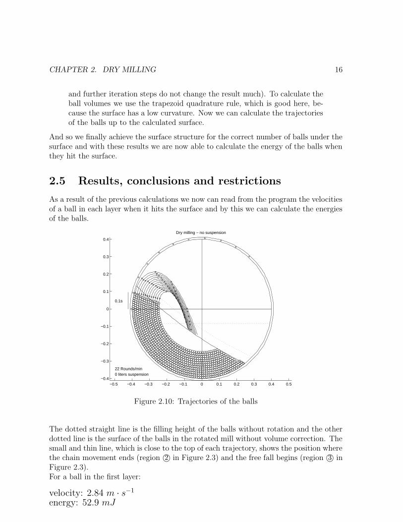
As a result of the previous calculations we now can read from the program the velocitiesof a ball in each layer when it hits the surface and by this we can calculate the energiesof the balls.
−0.5 −0.4 −0.3 −0.2 −0.1 0 0.1 0.2 0.3 0.4 0.5−0.4
−0.3
−0.2
−0.1
0
0.1
0.2
0.3
0.4
0.1s
22 Rounds/min0 liters suspension
Dry milling − no suspension
Figure 2.10: Trajectories of the balls
The dotted straight line is the filling height of the balls without rotation and the otherdotted line is the surface of the balls in the rotated mill without volume correction. Thesmall and thin line, which is close to the top of each trajectory, shows the position wherethe chain movement ends (region 2© in Figure 2.3) and the free fall begins (region 3© inFigure 2.3).For a ball in the first layer:
velocity: 2.84 m · s−1
energy: 52.9 mJ

CHAPTER 2. DRY MILLING 17
Compared to the speed of the mill at the wall, which is 0.9 ms−1, this is a quite highvalue. But of course the calculated velocity is an upper bound because of the rear-rangement of the balls: the calculated curves for the different layers come closer thantwice the radius of a ball, which is the minimal distance of two balls. So the layers willrearrange because the collision angle is very small (they fly nearly parallel). And by thisrearrangement the energy is distributed to the inner layers that do not have so muchenergy compared to the first layer.But these calculations are based on several assumptions in which errors are included:
1. In reality our mill is of cause 3D and not 2D. A cut through this 3D mill would notconsist of equal sized discs and we would have a certain movement in the directionof the main axis.
2. We considered a perfect layer structure but this is not the case in reality: in thefirst layer we have almost the assumed perfect layer structure, only in the regionof the steel bars there are small disturbances. But beginning with the second layerthe balls will fit to the gaps of the outer layer and by this the layer structureis getting worse and worse when we move to the center of the cylinder. Furtherwe assumed that the angular velocity of the different layers is the same than theangular velocity of the mill. This is in general not the case since due to thenon perfect layer structure the balls are sliding down from each other and so theangular velocity of the inner layers change.
3. The ”steady state” assumption is generally true but there may be some changesbecause of the gaps between layers and the periodical influence of the steel barsat the cylinder wall. But since there are enough balls following from behind andsince there are no such gaps in the other layers, we assume that this has not a biginfluence on the movement.
4. We neglect the self-rotation of the balls itself because in the cylinder the balls willinteract and rotate against each other and so we will not get very fast rotationspeeds.
In this chapter we were able to give an approximate upper bound for the energy of aball from the calculation of the energy of a ball in the first layer. Further we were ableto get approximate values for the energies of the balls in each other layer.Now we can go on with our calculations and include the influence of the suspensioninside.

Chapter 3
Wet Milling with Liquid at Rest
3.1 Basic ideas and assumption
Now we can consider the influence of the suspension. Ball milling with suspension iscalled wet milling in literature (see Figure 3.1). For simplification in our first model weare going to consider the suspension at rest. Of course in reality, this is not true. Butby this assumption we can get important estimates. Further we assume the surface ofthe suspension to be a horizontal line.
Suspension
Figure 3.1: Wet milling with suspension at rest
Considering the balls inside the suspension, beside gravitational force and centrifugalforce there are two additional forces: buoyancy force and Stokes force (see Figure 3.2).These forces are acting when the balls are under the surface line of the suspension. Ifthe balls are leaving the suspension in this model, these two additional forces are notacting any more.The different forces acting on a ball are :
FC : centrifugal force (in radial direction)
18

CHAPTER 3. WET MILLING WITH LIQUID AT REST 19
F
FA
F
F
V
S
G
C
Figure 3.2: Forces acting on a ball in liquid
FG : gravitational forceFA : buoyancy force (opposite direction of FG)FS : Stokes force (opposite direction of velocity V )V : velocity of ball (perpendicular to FC)
3.2 Movement of balls
Now we consider the motion of balls with liquid at rest. As considered in dry milling(see Figure 2.3), we consider the movement of balls in three different regions.
In region 1© the movement of the balls is nearly the same as in dry milling but thecritical angle is changed because of the buoyancy force. In region 2© the movement ofthe balls is nearly the same as in dry milling again because the influence of the Stokesforce is taken by the following balls and so by the steel bars at the end. The influenceof the buoyancy force will change the position of the balls losing contact with the chain.In region 3© the balls start losing contact with the balls behind and begin to fall downfreely under the influence of Stokes force, buoyancy force and gravitational force.
The critical angles for the k-th layer can be determined like in dry milling, only thebuoyancy force has to be included. This critical angles αck are now given by the followingformula :
αck = arcsinm(R − (2k − 1)r)ω2
(m − m) · gwhere m is the mass of the volume of a ball replaced by suspension.To describe the movement of balls after losing contact with the cylinder wall, considerthe forces acting on a ball in region 2©:
FG : gravitational force

CHAPTER 3. WET MILLING WITH LIQUID AT REST 20
F
ϕ F cos
F
a
V
G
A
Gϕ
Figure 3.3:
FA : buoyancy forcea : acceleration of a ball towards the center of the mill.V : velocity of a ball perpendicular to a.
Since a is perpendicular to V it follows that |V | is constant. But a is not a constantbecause a = a(ϕ). By this we obtain the ODE:
d
dt
(
V1
V2
)
=
(
(m − m) · gm
)
(
V1V2
V 21 +V 2
2−V 2
1
V 21 +V 2
2
)
(3.1)
Considering the forces acting on a ball in region 3© shown in Figure 3.3, we obtain thefollowing equation :
F
F
S
a
G
A
V
F
Figure 3.4: Forces acting in the movement in a chain
d
dt
(
V1
V2
)
=1
m
−FSV1√
V 21 +V 2
2
(m − m) · g − FSV2√
V 21 +V 2
2
(3.2)
with FS = ....

CHAPTER 3. WET MILLING WITH LIQUID AT REST 21
Technical realization: Inside the suspension, buoyancy force and Stokesforce are acting, above the suspension surface not. To distinguish thesecases, in each step the program compares the distance from the balls andthe surface to the x-axis. If the distance of the balls from the x-axis isbigger than that of the surface, then the program runs without consideringStokes and buoyancy forces. But here a new problem appears: if balls crossthe suspensions surface, this means a discontinuity of the acting force on aball in our calculations. Nevertheless this will not produce any importantnumerical errors, because our maximal step size is small enough.In spite of this the effect of balls leaving and falling back onto the suspension’ssurface will be stronger than just a discontinuity of the force. So curves whichleave the suspension must be considered carefully.
3.3 Surface structure of the balls
To calculate the surface structure in wet milling we make the same force equilibriumansatz as in dry milling, we only have to include the buoyancy force.
G
F
F
F
F A
G
C
αβ
µ
Figure 3.5: Forces acting on a mass point at the surface in suspension
Considering the additional buoyancy force we get the formula for the surface structurein wet milling as follows:
x2 + (y − (m − m) · gmω2
)2 = A2e2µ arctan(y−
(m−m)·g
mω2x
) (3.3)
This is nearly the same implicit equation as in dry milling (2.4). Normally the frictionalcoefficient µ has to be modified because of the influence of the suspension, but since wedo not have any measurements or values from literature we keep the same value as indry milling.

CHAPTER 3. WET MILLING WITH LIQUID AT REST 22
3.4 Result and conclusion
We achieved the following results for the milling with suspension at rest and we compareit with dry milling.
Critical Angle Velocity energyDry milling 10◦ 2.7 ms−1 48 mJWet milling300 l of suspension 12◦ 0.95 ms−1 5.9 mJ400 l of suspension 12◦ 0.95 ms−1 5.9 mJ
According to our result, we can conclude :
• The influence of the Stokes force is rather big in region 3© in Figure 2.3 as wecompare the resulting velocities when hitting the surface.
• The different filling heights change the form of the curves of the balls, but thevelocities of the balls when they hit the surface of balls do not differ much.
• Like in dry milling the layers will rearrange in wet milling, too, and so we get anupper bound for the energies and the velocities.

CHAPTER 3. WET MILLING WITH LIQUID AT REST 23
Ball curves for resting suspension
−0.5 −0.4 −0.3 −0.2 −0.1 0 0.1 0.2 0.3 0.4 0.5−0.4
−0.3
−0.2
−0.1
0
0.1
0.2
0.3
0.4
0.1s
22 Rounds/min300 liters suspension
Wet milling − suspension at rest
−0.5 −0.4 −0.3 −0.2 −0.1 0 0.1 0.2 0.3 0.4 0.5−0.4
−0.3
−0.2
−0.1
0
0.1
0.2
0.3
0.4
0.1s
22 Rounds/min400 liters suspension
Wet milling − suspension at rest

Chapter 4
Wet Milling with Moving Liquid
The suspension will be moved by the rotation of the cylinder just like the balls. Furtherthe movement of the suspension influences the movement of the balls and vice versa.In this chapter a moving suspension and its influence on the balls’ movement will bemodeled. On the other hand the balls’ influence on the suspension will be neglected.
4.1 The velocity field of the suspension
First the movement of the suspension without any balls has to be calculated. Themain difference to the balls’ movement is that the suspension is a continuous medium,while balls are discrete objects. So the balls’ movement can be described by ordinarydifferential equations, while the suspension’s movement is the solution of the Navier-Stokes-equation, a partial differential equation.If we have the cylinder filled with a certain volume of suspension, we are interested intwo outputs:
• The velocity field of the suspension
• The surface structure of the suspension
Again it is reasonable to consider only a 2D-model, for the same reasons as with theballs’ movement.
Calculating the surface structure is a so called “free boundary problem”, which is quitecomplicated. So we first consider the easier case, when there is no surface, i.e. the wholecylinder is filled with liquid.
We used the program Fluent, a numerical solver for Navier-Stokes-equations, andachieved the following result.In Figure 4.1 the angular velocity field is plotted. The radial velocities are almost zeroeverywhere, so we have nearly a perfect rotation process around the main-axis of thecylinder, respectively the mid point of the circle. So it can be concluded that gravitationhas nearly no influence on the movement of the suspension (otherwise the fix point of
24

CHAPTER 4. WET MILLING WITH MOVING LIQUID 25
Figure 4.1: The velocity field in the cylinder computed with Fluent
the rotation would be lower than the circle’s mid point).Furthermore the suspension’s velocity at the wall is the same as the cylinder’s velocity,i.e. we have no slip at the wall. Towards the middle of the cylinder the angular velocityof the suspension decreases, i.e. the outer liquid layers rotate faster than the innerlayers. From this fluent output the decrease of angular velocity towards the middle canbe estimated and can be used for the next step. (One can see that at a distance of 1
2R
with R the cylinder’s radius the angular velocity is about 75% of the cylinder’s angularvelocity.)
In our problem are surfaces corresponding to the filling heights of 300 l or 400 l ofsuspension, so reasonable velocity fields for these cases have to be achieved, too. Ofcause one cannot just take 300 l respectively 400 l of suspension and remove the balls,because then the filling heights would be much too low. The considerations must beperformed for the movement of such an amount of suspension, such that the same fillingheights are achieved as if there were balls. Hence the volume of the balls (207 l) has tobe substituted by the same volume of suspension to achieve the same filling heights. Sothe calculations have to be performed for suspension volumes of 507 l and 607 l.
Unfortunately, we were not able to perform this free boundary calculations becauseof the numerical instability. So the following velocity fields were constructed by ourexpectations to reality.

CHAPTER 4. WET MILLING WITH MOVING LIQUID 26
These are the constructed velocity fields for 300 l and 400 l.
300 liters 400 liters
−0.5 −0.4 −0.3 −0.2 −0.1 0 0.1 0.2 0.3 0.4 0.5−0.4
−0.3
−0.2
−0.1
0
0.1
0.2
0.3
0.4
0.1s
22 Rounds/min300 liters suspension
Wet milling − given suspension velocity field
−0.5 −0.4 −0.3 −0.2 −0.1 0 0.1 0.2 0.3 0.4 0.5−0.4
−0.3
−0.2
−0.1
0
0.1
0.2
0.3
0.4
0.1s
22 Rounds/min400 liters suspension
Wet milling − given suspension velocity field
Bigger pictures are attached at the end of this section.
These velocity fields are constructed by starting with the velocity fields of the calculatedcase with the whole cylinder filled (Fluent output). Then a horizontal surface line isdrawn at the correct filling height for the given volume. The suspension velocity vectornear this line must be parallel to it. By conservation arguments one can conclude thatthe velocity at the surface must be the same as the velocity of the cylinder wall. By aweight function which is 1 at the surface line and strongly decreasing with increasingdistance we combine the two vector fields.
Technical realization: In the Matlab-program the velocity field is savedin a cartesian 26 × 26-grid. So arbitrary velocity fields can easily be usedfor the ball movement calculations. The velocity vector at an arbitrarycoordinate inside the mill and under the suspension surface is achieved bybilinear interpolation of the four surrounding gridpoint vectors.
In reality the surface of the suspension will not be a horizontal line, but to obtain anynumerical estimate it was chosen this way. At least from the given viscosity it can beestimated that its slope should be much smaller than the slope of the balls’ surface.This is certainly one point where the model should be improved.
These constructed velocity fields will be used for the next step.

CHAPTER 4. WET MILLING WITH MOVING LIQUID 27
Suspension velocity fields
−0.5 −0.4 −0.3 −0.2 −0.1 0 0.1 0.2 0.3 0.4 0.5−0.4
−0.3
−0.2
−0.1
0
0.1
0.2
0.3
0.4
0.1s
22 Rounds/min300 liters suspension
Wet milling − given suspension velocity field
−0.5 −0.4 −0.3 −0.2 −0.1 0 0.1 0.2 0.3 0.4 0.5−0.4
−0.3
−0.2
−0.1
0
0.1
0.2
0.3
0.4
0.1s
22 Rounds/min400 liters suspension
Wet milling − given suspension velocity field

CHAPTER 4. WET MILLING WITH MOVING LIQUID 28
4.2 The balls’ movement under the suspensions’ in-
fluence
Now the suspension’s influence on the balls’movement is modeled. Compared to the casewith suspension at rest we obtain an other valuefor the Stokes force, while the three other forcesacting on one ball (gravitation, centrifugal force,buoyancy) are of the same size. The Stokes forceacting on one ball points in the opposite direc-tion of the relative velocity between ball and sus-pension. So the form of the curves the balls de-scribe can be influenced strongly by the movingsuspension. Again it should be remarked thathere the balls’ influence to the suspension is notmodeled.
Technical realization: First it is checked whether a given ball is insidethe suspension or above. In the second case, buoyancy and Stokes forceare set to zero, while in the first case the suspension’s velocity at the ball’sposition is calculated by bilinear interpolation. Then the Stokes force iscalculated from the relative velocity of ball and suspension. Gravitation andcentrifugal force (if active) are added. The integrations are performed likein the previous cases.
The maximum kinetic energies of balls hitting the surface are:
Filling volume Velocity Kinetic energy
300 liters 0.951 ms−1 5.93 mJ400 liters 0.955 ms−1 5.98 mJ

CHAPTER 4. WET MILLING WITH MOVING LIQUID 29
Ball curves for moving suspension
−0.5 −0.4 −0.3 −0.2 −0.1 0 0.1 0.2 0.3 0.4 0.5−0.4
−0.3
−0.2
−0.1
0
0.1
0.2
0.3
0.4
0.1s
22 Rounds/min300 liters suspension
Wet milling − given suspension velocity field
−0.5 −0.4 −0.3 −0.2 −0.1 0 0.1 0.2 0.3 0.4 0.5−0.4
−0.3
−0.2
−0.1
0
0.1
0.2
0.3
0.4
0.1s
22 Rounds/min400 liters suspension
Wet milling − given suspension velocity field

Chapter 5
Conclusions and Outlook
5.1 Comparing the three models
The maximum energies of balls hitting their surface in the three considered cases are:
Filling volume 300 liters 400 liters
Dry milling 2.84 ms−1 52.9 mJ 2.84 ms−1 52.9 mJ
Resting suspension 0.993 ms−1 6.47 mJ 0.987 ms−1 6.39 mJ
Moving suspension 0.951 ms−1 5.93 mJ 0.955 ms−1 5.98 mJ
30

CHAPTER 5. CONCLUSIONS AND OUTLOOK 31
−0.5 −0.4 −0.3 −0.2 −0.1 0 0.1 0.2 0.3 0.4 0.5−0.4
−0.3
−0.2
−0.1
0
0.1
0.2
0.3
0.4
0.1s
22 Rounds/min0 liters suspension
Dry milling − no suspension
−0.5 −0.4 −0.3 −0.2 −0.1 0 0.1 0.2 0.3 0.4 0.5−0.4
−0.3
−0.2
−0.1
0
0.1
0.2
0.3
0.4
0.1s
22 Rounds/min300 liters suspension
Wet milling − suspension at rest
−0.5 −0.4 −0.3 −0.2 −0.1 0 0.1 0.2 0.3 0.4 0.5−0.4
−0.3
−0.2
−0.1
0
0.1
0.2
0.3
0.4
0.1s
22 Rounds/min400 liters suspension
Wet milling − suspension at rest
−0.5 −0.4 −0.3 −0.2 −0.1 0 0.1 0.2 0.3 0.4 0.5−0.4
−0.3
−0.2
−0.1
0
0.1
0.2
0.3
0.4
0.1s
22 Rounds/min300 liters suspension
Wet milling − given suspension velocity field
−0.5 −0.4 −0.3 −0.2 −0.1 0 0.1 0.2 0.3 0.4 0.5−0.4
−0.3
−0.2
−0.1
0
0.1
0.2
0.3
0.4
0.1s
22 Rounds/min400 liters suspension
Wet milling − given suspension velocity field
The following conclusions can be drawn:
• Dry milling vs. wet milling
– The velocities respectively the energies of balls hitting the surface formed bythe other balls are much lower in both wet milling cases compared to the drymilling case. The reason is that the suspension drags the balls’ free fallingby the Stokes force. Here the results for a moving suspension are quite closeto those with a resting suspension.

CHAPTER 5. CONCLUSIONS AND OUTLOOK 32
• Resting suspension vs. moving suspension
– The main difference between moving and resting suspension is that a movingsuspension takes the balls much higher and longer over the surface than aresting one. Especially near the surface the suspension drags balls towardsthe right side of the cylinder.
– As an important result the number of balls forming the surface is much lower,if there are more balls being lifted up. Therefore there will be even more flyingballs, and even a hollow between flying balls and balls forming the surfacecan appear.
– Rearrangement, which reduces the velocities for the balls in the outer layersby the transport of energy to the inner layers, is stronger the closer the layerscome. Therefore it will take place mostly in the wet milling case with restingsuspension, while the effect will be lower in the case of moving suspension.
– This effect is much stronger than the fact that the calculated energies in thecase of moving suspension are a little bit lower than in the resting case. Thereason for this at a first glance surprising data is that balls hit the surface at apoint where the suspension is moving upwards again. Of cause in this regionthe suspension velocity field will be changed totally by the balls’ movement.Therefore the energy difference between the two wet milling cases seems tobe negligible in reality.
• 300 l vs. 400 l
– In the dry milling case there is no difference between the two cases, becausethere is no suspension at all.
– In both wet milling cases the final energies do not differ very much (comparethe table at the beginning of Chapter 5).
– Especially in the case of moving suspension balls are lifted up higher in thecase of 400 l. Therefore there are more flying balls if more suspension is takenand as a result – like in the previous consideration – less rearrangement. Sowith 300 l of suspension there will be less flying balls. But the difference isnot very big.
• Number of balls
– It is obvious that the number of flying balls and the energies of balls hittingtheir surface can easily be reduced by just taking more balls. Firstly thesurface will be lifted up, secondly a hollow will be prevented and thirdly theeffect of rearrangement will be increased.

CHAPTER 5. CONCLUSIONS AND OUTLOOK 33
5.2 Conclusions and results
From our model we were able to derive answers to the questions posed by the company.
Question: What is the movement of the balls when the mill is rotating?
Answer: The balls will be lifted up in the left region and fall back onto their ownsurface like in Figure 5.1.
−0.5 −0.4 −0.3 −0.2 −0.1 0 0.1 0.2 0.3 0.4 0.5−0.4
−0.3
−0.2
−0.1
0
0.1
0.2
0.3
0.4
0.1s
22 Rounds/min300 liters suspension
Wet milling − given suspension velocity field
Figure 5.1: Movement of the balls for 300 l suspension
Question: Which surface do the balls form?How will the surface of the suspension look like?
Answer: The ball surface will look like in the curve in 5.1 where the trajectories ofthe balls end. Further we expect the surface of the suspension to be close to aline with a small curvature near the walls but we were not able to solve this freeboundary problem.
Question: What is the energy of the balls when they hit the ball surface?
Answer: The suspension reduces the velocity of the falling balls a lot. So the energyfor each ball collision will probably not be much higher than 6 mJ . If we takethe rearrangement of the different layers into account the maximal energy will beeven lower.
Question: What is the dependence on the volume of the suspension?
Answer: The volume of the suspension does not influence the energy of the balls hittingthe surface very much. With more suspension the amount of balls over the balls

CHAPTER 5. CONCLUSIONS AND OUTLOOK 34
surface is increased. Further with only 300 l of suspension the balls can leave thesuspension (see Figure 5.1) and with 400 l this will not happen if we consider thesuspension to be taken with the balls a little bit (see Figure 5.2).
−0.5 −0.4 −0.3 −0.2 −0.1 0 0.1 0.2 0.3 0.4 0.5−0.4
−0.3
−0.2
−0.1
0
0.1
0.2
0.3
0.4
0.1s
22 Rounds/min400 liters suspension
Wet milling − given suspension velocity field
Figure 5.2: Movement of the balls for 400l suspension
5.3 Parameter discussion
In our model we have at least three important parameters:
1. Rotation speed:In our model we can change the rotation speed of the mill to get different resultse.g. different trajectories or hitting energies. But the engines are optimized forone certain rotation speed and so this parameter cannot be changed.
2. Volume of suspension:In the cases considered in our model (300 l or 400 l) this parameter seems notto be important for the energy of balls hitting the surface. From the model wecan observe that more suspension means that more balls are lifted up above thesurface calculated for the ball filling and with fewer suspension the balls are liftedout of the suspension.
3. Volume of balls:An increase of the number of balls would reduce the number of flying balls. Butthe problem that can occur is that the filling could become too heavy.
As a result of this we can conclude that for a lower kinetic energy of the balls when theyhit the surface it is better to use more balls and more suspension.But in this result the efficiency of the mixing process is not taken into account.

CHAPTER 5. CONCLUSIONS AND OUTLOOK 35
5.4 Outlook
For further research several improvements of the model can be performed:
1. The influence of the different layers to each other (rearrangement) could be de-scribed.
2. The surface of the suspension could be calculated by solving the free boundaryproblem. Then in the model the correct surface can be used.
3. The influence of the balls to the suspension could be modeled.
4. The whole movement of the balls and the suspension at once could be modeled.
5. The process could be modeled as an n-body problem.
6. The mixing process could be taken into account in order to increase the efficiencyof the ball mill.

Bibliography
[1] Rose, H.E., Sullivan, R.M.E.: A Treatise on the Internal Mechanics of Ball, Tubeand Rod Mills. London: Constable 1957.
[2] Freiermuth, D.: Verteilung der Kugelenergie in Kugelmuhlen in Abhangigkeit vonden Mahlparametern. Dissertation, Frankfurt am Main 1981.
[3] Langemann, H.: Kinetik der Hartzerkleinerung Teil III: Die Kinematik derMahlvorgange in der Fallkugelmuhle. Chemie-Ing.-Techn. 34. Jahrg. 1962/ Nr.9.
[4] Barth, W.: Der Arbeitsverbrauch von Rohrmuhlen. Technische Mechanik und Ther-modynamik 1. Band Nr. 9 September 1930.
36