dynamic testing of 210 mw generator
TRANSCRIPT
Presented by
Amilkanthwar P. A.Assistant Engineer (Gen)

2
PURPOSE OF DYNAMIC TESTING OF THE GENERATOR
To ensure the healthiness and operation/Stability of
Generator differential protection under actual fault conditions. Over all differential protection under actual fault conditions. Generator back up impedance protection under actual fault conditions. Generator earth fault protection under actual fault conditions. Generator differential protection while supplying through currents. Over all differential protection while supplying through currents.
To obtain and check the Short circuit characteristic of the generator Open circuit characteristic of the generator
To ensure the healthiness of all the CTs and its associated circuits.
3
1.TA set is running at 3000 rpm.2.Faults created at different locations (as per the diagram)3.Controlled excitation for controlling the fault current.4.Set up required for measurements while test.

4
ROUTINE PROCEDURE OF DYNAMIC TESTING
1. Modifications Require to facilitate controlled Excitation
2. Faults to be created in power circuit
3. Different Tests to be Carried out by feeding the faults

5
1. Replace existing manual pot with Spare digital pot already prepared for dynamic testing
2. Remove Excitation Transformer HV links and Extend 6.6KV supply to Excitation Transformer HV side
3. Extend Excitation protection tripping to 6.6 KV Bkr 4. Inhibit FFB closing to bypass the FF disturb proton.5. Tier fan supply: Extend the 230V ac supply to tier fan
from station supply6. Thyrister Fan Supply: Extend 415 V 3phase supply to
thyrister fans through FF supply7. Bypass Generator to Turbine Tripping.
6
1. Roll the TA set to 3000 RPM2. Establish Generator Cooling System3. Close the Field Breaker and go on
increasing excitation current till operation of Gen diff proton. & master trip relay 86G1/86G2 along with FB tripping.
5 min
7
1. Short metro-sils of generator differential relay.
2. Close the Field Breaker Go on increasing excitation current till operation of relay.
3. Observe operation of Master trip & FB
10 min(15)

8
1. Remove shorting from point A when TA set is at bar
60 min(120)
1. Trip the TA set & Bring to Barring speed45 min(60)
9
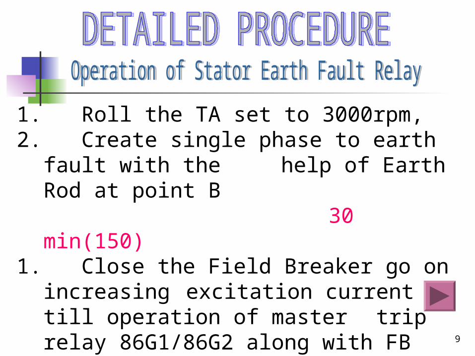
1. Roll the TA set to 3000rpm, 2. Create single phase to earth fault with the
help of Earth Rod at point B30 min(150)
1. Close the Field Breaker go on increasing excitation current till operation of
master trip relay 86G1/86G2 along with FB Tripping.
2. Remove the earth rod10 min (160)

10
1. Close the isolator to connect Three phase shorting at point "C“
2. Bypass the 220KV Bus-Bar diff. Protn.
3. Bypass the tripping of 50LBB protection
10 min(170)1. Close the field breaker, increase
excitation and record the short circuit characteristics
15 min(185)

11
Open the isolator to remove the shortings10 min (195)
Close the field breaker and increase excitation record the Open circuit characteristics
15 min(210)
12
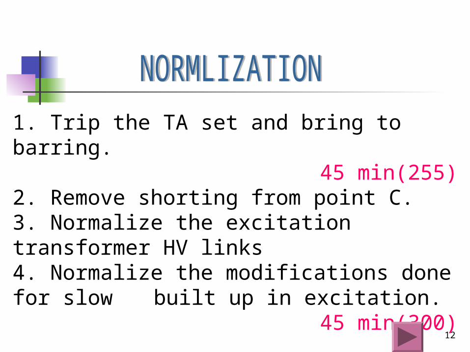
1. Trip the TA set and bring to barring.45 min(255)
2. Remove shorting from point C.3. Normalize the excitation transformer HV links4. Normalize the modifications done for slow built up in excitation.
45 min(300)
13
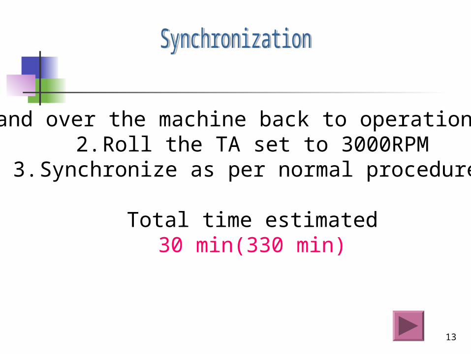
1. Hand over the machine back to operation staff2. Roll the TA set to 3000RPM
3. Synchronize as per normal procedure.
Total time estimated30 min(330 min)

14scheme
Proposed by Testing Section PTPS Parli
15
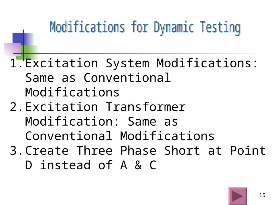
1. Excitation System Modifications: Same as Conventional Modifications
2. Excitation Transformer Modification: Same as Conventional Modifications
3. Create Three Phase Short at Point D instead of A & C

16
1. Short phase side CT for Generator Diff and 220KV for Over All Diff Protection
2. Close the Transfer Bus Isolator to Connect Three Phase Short to GT HV Side
3. Bypass the 220KV Bus-Bar diff. Protection.4. Bypass the tripping of 50LBB protection5. Roll the TA set to 3000 RPM6. Establish Generator Cooling System7. Close the Field Breaker and go on increasing
excitation current till operation of Gen diff protection & FB tripping. 10min

17
1. Normalize the CT circuit of Generator diff protection
2. Close the Field Breaker and go on increasing excitation current till operation of relay. Take the readings.
3. Observe operation of Master trip with FB tripping.4. Normalize the CT circuit of over all diff
Protection.10min (20)
18
1. Close the field breaker, increase excitation gradually & record the short circuit characteristics
2. Make the FB OFF3. Open the isolator to isolate three phase shorting
from point D4. Give clearance to remove shorting from point D5. Normalize the 220KV Bus-Bar diff. Protection.6. Normalize the tripping of 50LBB protection
15 min(35)
19
1. Create single phase to earth fault with the help of Earth Rod at point B
2. Close the Field Breaker 3. Go on increasing excitation current till operation
of master trip relay 86G1/86G2 along with FB tripping.
4. Remove the earth rod10 min(45)

20
Close the field breaker, increase excitation gradually & record the Open circuit characteristics
15 min(60)

21
1. Trip the TA set and bring to barring.45 min(105)
1. Normalize the excitation transformer HV links
2. Normalize the modifications done for slow built up in excitation.
45 min(150)

22
Hand over the machine back to operation staff
Roll the TA set to 3000RPM
Synchronize as per normal procedure.
Total time estimated15 min(165min)

23

24
Close link X and Open link Y at TTB for Phase side diff CT

Achievements By Proposed Dynamic Testing Procedure
1.Total Estimated time for completion of test is 165 minutes. Lot of time is saved. 2.Operation of Generator and overall Differential Protection can be tested dynamically under actual fault condition 3.Actual and accurate operating point can be located.4.Healthiness of Excitation system gets proved in this proposal.5.Safe and fine control through excitation can be achieved.6.By changing the 3phase shorting location from C to D we can synchronize the unit by opening the transfer bus isolator and shorting removal work can be done even after taking the unit on load.7.The parallel activities can be planned such as excitation normalization and excitation transformer normalization to save the time.