dynamic study of mo/zsm-5 catalyst for ch
TRANSCRIPT

DYNAMIC STUDY OF Mo/ZSM-5 CATALYST FOR CH4
DEHYDROAROMATIZATION
Hadi Almusawa
Problem Report submitted
to the Statler College of Engineering and Mineral Resources
at West Virginia University
In partial fulfillment of the requirements for the degree of
Master of Science in
Chemical engineering
Hanjing Tian, Ph.D., Chair
Dr. John Hu, Ph.D.
Dr. Fernando Lima, Ph.D.
Department of Chemical Engineering
Morgantown, West Virginia
2020
Keywords: Methane dehydroaromatization, Mo/ZSM-5, zeolite catalysts, molybdenum,
membrane reactor, fixed-bed reactor
Copyright 2020 Hadi Almusawa

ABSTRACT
DYNAMIC STUDY OF Mo/ZSM-5 CATALYST FOR CH4
DEHYDROAROMATIZATION
Hadi Almusawa
Methane dehydroaromatization (CH4-MDA) is a highly promising venture for natural gas
utilization/exploitation, i.e., direct conversion of methane (CH4) to liquid aromatics (benzene)
and hydrogen. This process is a catalytic reaction and therefore, is subject to all the advantages
and constraints of catalysis. This study discussed the structure and reactivity of Mo/ZSM-5
zeolite catalysts and their effect on the active conversion of methane to valuable aromatic
products such as benzene: 1) The preparation and characterization of Mo/ZSM-5, which are
crucial steps in any catalytic reaction process since a better performing catalyst consequently
leads to better outcomes; 2) An examination of the structure and properties of the prepared and
characterized molybdenum zeolite catalyst (Mo/ZSM-5) reveals that the MoOx sites are
responsible for the performance of the catalyst, as discussed in surface-active structure
performance relationship subsection. In addition, there are some studies compared the reaction
performance of Mo/ZSM-5 with other catalytic system such as molybdenum carbide; 3) The
performance of this catalyst is essentially determined by the nature of surface desorption, the
propensity of mass diffusion of benzene and naphthalene by-products across active sites, and
the propensity for coking. These three factors are influenced by multiple parameters such as
molybdenum content, the reaction temperature, the space velocity and the reaction time, which
have been discussed in detail in this study. In order to overcome the challenge of coking, which
impedes the effectiveness of the MDA process, fundamental discoveries have been explored
by the researchers, along with their major impacts. 4) The final section of this paper explores
the best reactor design by comparing the structure and performances of a fixed-bed reactor
(FR) and a membrane reactor (MR).

ACKNOWLEDGEMENTS
I wish to direct my truthful gratitude to my advisor Dr. Hanjing Tian for his guidance
and encouragement during this work. I am also very grateful to the members of my advisory
committee. Dr. John Hu and Dr. Fernando Lima and Dr. Charter Stinespring for their helps.
I must especially thank department chair on Graduate Student Service, Dr. Charter
Stinespring for his help, and guides throughout my entire graduate program.
I am thankful to all graduate students and faculties in the Chemical Engineering
Department for their friendliness and warmth that has made my stay in Morgantown pleasant
and productive.
abroad with full scholarship.
Last, I wish to thank my family in Saudi Arabia for their love and support throughout
the course of my education in the United States.

iv
TABLE OF CONTENTS
Title Page ………………………………………………………………………………………….... i
Abstract ……………………………………………………………………………………... ii
Acknowledgements……………………….………………………………………………... .iii
Table of Contents ………………………………………………………………………….... iv
1: Introduction …………………………………………….……………..……………….... .1
2: Catalyst Preparation and Characterization ……………………..……………..…………. .3
2.1 ZSM-5 Zeolite (Preparation and Structure) …………….……….………...5
2.2 Mo/ZSM-5 Catalyst Preparation Methods …………………….….....… .12
2.3 Surface MoOx Structure of Prepared Mo/ZSM-5 Catalyst …...…16
3: Surface Active Structure-Performance Relationship…………………..……………..….. 17
3.1. The location and Active Structure of Mo Carbide …………………….. 18
3.2 Surface Desorption and Mass Diffusion of Aromatics ….………….….. 20
3.3 Parameters for Catalytic Performance ………………………………..… 23
3.4 Carbon Deposition Species and Catalytic Deactivation …………….…. 27
4: Reactor Design …………………………………………..…………………………..…... 30
4.1 Membrane reactor………………..……………………………….…….. 31
4.2 Fluidized bed reactor……………………..………………………………35
Conclusion ……………………………………………………………………………….…..39
References ……………………….…………...…………………………………….…..……41

1
1. INTRODUCTION
Methane dehydroaromatization, commonly known as MDA, is one of the prime
technological innovations for decades and shows great promise and potential in the process of
methane (CH4) conversion to liquid aromatics and benzene. Methane (CH4) is the simplest
alkane and quintessentially the main component of natural gas, which can thus be converted
into aromatic products in the process of dehydroaromatization and provided three main
conditions; (1) Mo/ZSM-5 catalyst; (2) temperatures about 700oC and (3) non-oxidizing
environmental conditions [32]. Large-scale/commercial MDA is yet to be achieved since the
Mo/ZSM-5 zeolite catalyst tends to deactivate due to coking. This is a significant challenge in
MDA since the formation of coke in the coking process essentially cannot be avoided under
the MDA conditions [14]. However, significant progress has been made to reduce the coking
rate in order to use the Mo/ZSM-5 catalysts, which have short lifespan but are the most efficient
synthesizers of the desired light polycyclic aromatic products [15]. One of the main examples
is the use of oxygen-permeable ceramic membranes that inject small amounts of oxygen (in
pulses) into the processes without necessarily compromising the non-oxidizing conditions,
which helps the decomposition of excess coke. The main aspects that will be discussed include;
Mo/ZSM-5 catalyst preparation methods and characterization; ZSM-5 Zeolite (Preparation and
Structure); Surface MoOx Structure of Prepared Mo/ZSM-5 Catalyst; Surface active structure-
performance relationship; the location and active structure of Mo carbide and the surface
desorption and mass diffusion of aromatics.

2
1.1 Definition of Main Terms and Concepts
Methane Dehydroaromatization (MDA): this is the process by which methane (CH4) is directly
converted into valuable materials such as benzene, toluene and xylene in industrial chemical
productions.
Zeolites: these are mineral structures occurring naturally and consisting of highly ordered
microporous crystalline aluminosilicate molecular sibs. They are mainly applied in industries
as molecular sieves, ion exchangers, catalysts, and commercial adsorbents.
ZSM-5 (Zeolite Socony Mobil–5): this is one of the aluminosilicate zeolites, constituent
members of the pentasil zeolite family. The chemical formula is NanAlnSi96–nO192•16H2O.
Figure 1 below shows the molecular structure of the ZSM-5 molecule, which will be the
primary focus of this paper.
FIGURE 1: THE MOLECULAR STRUCTURE OF ZSM-5 ZEOLITE, WITH WELL-DEFINED PORES AND
CHANNELS IN THE ZEOLITE
3
2. CATALYST PREPARATION AND CHARACTERIZATION
Preparation –An Overview
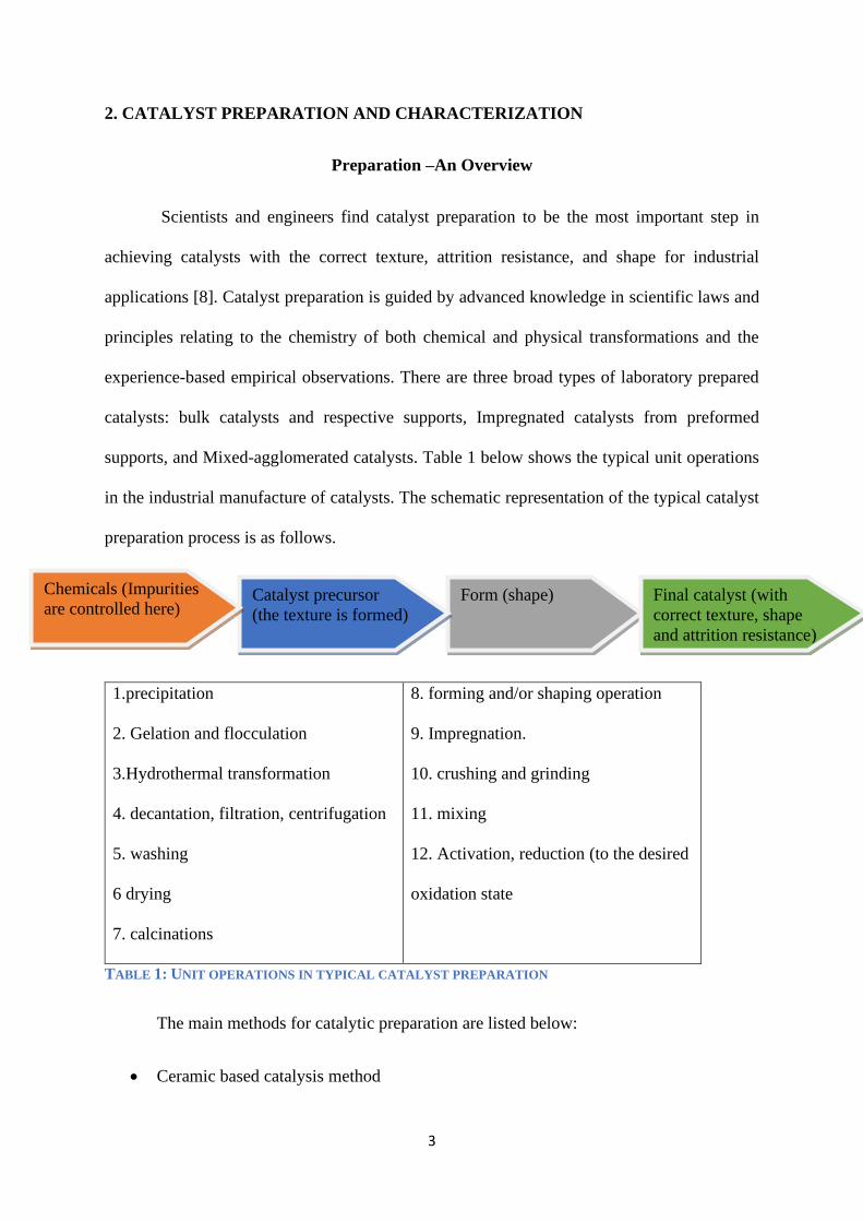
Scientists and engineers find catalyst preparation to be the most important step in
achieving catalysts with the correct texture, attrition resistance, and shape for industrial
applications [8]. Catalyst preparation is guided by advanced knowledge in scientific laws and
principles relating to the chemistry of both chemical and physical transformations and the
experience-based empirical observations. There are three broad types of laboratory prepared
catalysts: bulk catalysts and respective supports, Impregnated catalysts from preformed
supports, and Mixed-agglomerated catalysts. Table 1 below shows the typical unit operations
in the industrial manufacture of catalysts. The schematic representation of the typical catalyst
preparation process is as follows.
1.precipitation
2. Gelation and flocculation
3.Hydrothermal transformation
4. decantation, filtration, centrifugation
5. washing
6 drying
7. calcinations
8. forming and/or shaping operation
9. Impregnation.
10. crushing and grinding
11. mixing
12. Activation, reduction (to the desired
oxidation state
TABLE 1: UNIT OPERATIONS IN TYPICAL CATALYST PREPARATION
The main methods for catalytic preparation are listed below:
• Ceramic based catalysis method
Form (shape)
Catalyst precursor
(the texture is formed)
Chemicals (Impurities
are controlled here)
Final catalyst (with
correct texture, shape
and attrition resistance)

4
• Precipitation and co-precipitation method
• Impregnation method
• Sol-gel method
• Ion exchange method
• Adsorption method
• Deposition–precipitation methods
• Plasma method
• Micro-emulsion method
• Combustion method
• Electro -spinning methods
Characterization –An Overview
Remarkable improvements in characterization techniques have been applied for
catalysis research [17]. The major characterization techniques include the following:
Structural based characterization techniques: x-ray diffraction and absorption
spectroscopy and electron microscopy technique
Thermal adsorption and desorption techniques: pore structure and surface area,
temperature-programmed desorption and temperature-programmed reaction, thermal
analysis and thermogravimetry techniques, and microcalorimetry [11].
Optical spectroscopic methods: infrared spectroscopy, Raman spectroscopy, UV-
visible spectroscopy, electron spin resonance, and Nuclear magnetic resonance. [17, 22,
37].
Surface-sensitive spectroscopic techniques; X-ray and UV-photoelectron spectroscopy,
auger-electron spectroscopy, low energy ion scattering, and secondary, Ion-mass
spectroscopy [17].

5
2.1 ZSM-5 ZEOLITE (PREPARATION AND STRUCTURE)
Structure of ZSM-5 Zeolite
First synthesized ZSM-5 zeolite was dated back to 1969 by scientists Argauer and
Landolt [2]. The structure is described as a medium pore zeolite with channels characterized
by 10-membrane rings. It is composed of pentasil chains formed by the systematic linkage of
pentasil units by oxygen bridges. Each pentasil unit consists of eight, 5-membrane rings with
aluminum (Al)/ silicon (Si) and oxygen (O) vertex. The linked pentasil chains, therefore, form
corrugated sheets consisting of 10-ring holes, each with Si or Al vertices bonded by O bridges.
Additionally, the oxygen bridges connect each system of the 10-ring corrugated sheets to form
straight 10 ring channels that run parallel to the corrugated sheets (pore size estimated at 5.4–
5.6 Å) and sinusoidal 10-ring sheets that run orthogonal to the corrugated sheets. Inversion
points relate to two adjacent sheets. The unit crystal cells of ZSM-5 consist of 96 Si/Al sites
and 192 O sites. Depending on the Si to Al ratio, there are several compensating cations.
FIGURE 2: THE MOLECULAR STRUCTURE OF ZSM-5 ZEOLITE, SHOWING WELL DEFINED PORES
AND CHANNELS IN THE ZEOLITE
6
Preparation of a ZSM-5 zeolite catalyst
Zeolite catalysts are the most effective catalysts to date known for methane
dehydroaromatization. Their general chemical formula is (M n+) x/n (AlO2) x (SiO2) y mH2O,
where M=cation, m= number of moles of water of crystallization, x and y are the number of
Al-O and Si-O channels in the unit tetrahedral structure. The main steps for preparing
molybdenum Zeolite Socony Mobil–5 (Mo/ZSM-5) catalysts are hydrothermal synthesis, ionic
exchange, ad binding, and shaping. The following is a summary schematic diagram of the
ZSM-5 synthesis.

7
Aerosol (silica source)
Tetraalkylammonium compounds (TPABr) Aluminum sulphate
H2SO4 (sulphuric acid)
Stirred at
323K for 3
days and
cooled
with water
(Under reflux
conditions)
Stainless steel (435-473k)
Gel consisting of 4.38(TPA)
2O, 27.6 Na2O, Al2O3, 87.7
SiO2, 3262 H2O
Filtered and washed with hot
water.
Dried at 393K, for12 hours
and then calcined
ZSM-5 (SiO2 97.10 %,
Al2O3, 2.08 %, Na2O 0.78 %)
Ion Exchange (0.5M of
NH4NO3)
Dried and calcinated
ZSM-5

8
2.1.1 Conventional ZSM-5 Preparation
Conventional ZSM-5 is subjected to specifically, conventional hydrothermal treatment.
Silica source for the catalyst was tetraethyl orthosilicate (TEOS, 98%), and alumina source was
aluminum isopropoxide (Al(O-i-Pr)3). 1M sodium hydroxide pellets were added to form an
aqueous solution of tetra propylammonium hydroxide (TPAOH, 40 wt. %).
The preparation steps are presented below:
• Step1: preparation of the silicate solution: half of the TPAOH, TEOS (all of it), and
water (half also) are added to a polypropylene bottle and left in a shaker for 24 hours to
hydrolyze TEOS.
• Step 2: preparing of aluminate solution: when 22 hours have passed in the hydrolysis
of the TEOS timeline, add all Al(O-iPr)3, NaOH, and the remaining TPAOH, to a glass
beaker. Stir the mixture for 25 hours till a clear aluminate solution form.
• Step 3: preparing synthesis mixture: add all the silicate solution to the aluminate
solution and stir the resulting clear mixture vigorously for about 10 minutes.
• Step 4: hydrothermal treatment: fill the treatment mixture to a level of about 2/3 within
a Teflon lined autoclave enabled with magnetic stirring. Seal the autoclave and place it
in an oil bath at 150oC for a minimum of 3 hours and a maximum of 72 hours.
• Step 5: Purifying the product: cool the autoclave at room temperature and remove the
mixture containing dispersed crystals, which are then purified by centrifugation
accompanied by re-dispersion in water. This is done 4 times repeatedly.
• Step 6: calcination: calcinated the freeze-dried crystals at 500oC for 16 hours
The resulting product is ZSM 5 with a hollow structure, the aluminum and silicon are
distributed in heterogeneous form where the aluminum is at the surface and the silicon is at the
core. The silicon-rich core in the interior of the ZSM-5 zeolite crystal can be selectively

9
dissolved in alkali and re-crystallized on the exterior. However, this may not be very viable
when it comes to industrial-purpose synthesis since much aluminosilicate is dissolved anyway
[39].
2.1.2 Nonconventional Preparation of ZSM-5
Depending on the quantity and composition of the ZSM-5, the process can take several
hours days or even weeks to complete the crystalline ZSM-5 product, which is an improvement
given that the formation of natural zeolites takes hundreds of millennia to complete. Artificial
synthesis through hydrothermal synthesis is a major turntable but time-consuming given the
long hours of hydrolysis, crystallization, and purification. In industrial use, it becomes costly
and inefficient in terms of energy use and burdening operators [13]. To overcome these hurdles,
researchers have developed other nonconventional means to zeolite ZSM-5 production using
alternative but ultra-fast routes [25].
One of these new techniques, contrary to the hydrothermal technique, is the continuous
flow method, which synthesizes ZSM-5 by employing pressurized hot water under enormously
high temperature (370 °C) as the primary heating medium [21]. Industrial synthesis of ZSM-
5, in the continuous reactor contrary to the autoclave, proceeds to completion significantly
faster, with crystallization rate also happening remarkably faster. The continuous flow reactor,
in combination with the pressurized hot water as a heating medium, provides a feasible method
to reduce the time limit of zeolite crystallization.
Materials: TPAOH (40% aqueous solution) colloidal silica 40 wt % suspension in (H2O),
aluminum hydroxide (100%), and sodium hydroxide (pellets).
Synthesis mixture preparation: TPAOH solution, an aqueous solution of NaOH (20 wt %),
and aluminum hydroxide are mixed and vigorously stirred for 5 min, after this add colloidal

10
silica and continue stirring for an additional 30 minutes. Age this mixture in a plastic bottle at
90 °C placed in an oven rotating at 20 revolutions per minute to obtain a gel-like solution.
Synthesis of ZSM-5 under continuous flow: the apparatus is connected, as shown in the
figure above. Preheat the water circulating in the system gradually to the desired temperature
and sets the pressures accordingly to 23,000Pa using the pressure regulator. Feed the
synthesized gel to replace the water in circulation, as shown in the figure above. At the outlet
of the flow, cooling water is fed to cool the resultant slurry solution, which is at 260 °C. The
purpose of the vibrator is to shake the solution and to prevent precipitation of solids at
approximately 100 Hz. The slurry flowing out is centrifuged, washed and dried to obtain ZSM-
5 crystals. Under optimum operating conditions, the of ZSM-5 is 260g per day.
2.1.3 Solid-State Preparation of ZSM-5
Solid-state crystallization as a method of synthesis of ZSM-5 is a novel technique that
offers significant advantages over the conventional preparation technique. It generally involves
introducing an aluminosilicate nanogels containing a structure-directing agent into a solvent
and allowing this solvent to evaporate, hence forming dried nanogels of approximately 30%
solvent by weight. This is followed by the process of heating the dried nanogels until
crystallized ZSM-5 crystals of diameter 200nm and 2um are synthesized. The process is
described in detail below.
Materials: Tetrapropyl ammonium hydroxide (TPAOH, 1M solution in H2O), sodium
aluminate (NaAlO2, 8% wt. in H2O) tetraethylorthosilicate (TEOS, >99%), and lignin (0.1 M
NH4NO3)

11
Preparation (Experimental)
To prepare mesoporous ZSM-5 by solid-state crystallization, sodium aluminate (NaAlO2),
tetrapropyl ammonium hydroxide (TPAOH), tetraethylorthosilicate (TEOS), and water (H2O)
were mixed in the following ratio; 0.03NaAl2O3:0.25TPAOH:SiO2:80H2O. For efficacy,
PAOH and NaAlO2 were dissolved in water first, followed by the subsequent addition of TEOS
subjected to strong centrifugation at 600 revolutions per minute at room temperatures (ranging
between 20° C. and 25° C.). After adding TEOS, the mixture of the three was removed from
the centrifuge and incubated at higher temperatures of 80° C for approximately 12 hours until
a clear solution was formed. This mixture was additionally; left overnight at room temperature
to allow solvent evaporation. The dry gel was gathered and grounded into powder and
transferred to a pre-heated Teflon-lied autoclave (140° C) for crystallization. The mixture was
left in the autoclave for 12 hours without the addition of any water. Despite its use, an autoclave
is not required in solid-state crystallization technique as no significant pressure is generated as
compared to the conventional hydrothermal crystallization of ZSM-5 where the autoclave as a
result of steaming generates a significant pressure of 1-4 MPa; depending on the filling volume
of the solution used. Therein this technique also used containers such as air-tight glass bottles,
which can provide a tight-seal at elevated temperature and are also resistant to basic liquids.
The autoclave was used to compare the efficiency of this technique with that of traditionally
prepared ZSM-5. Next, the fully crystallized ZSM-5 was removed from the autoclave, and
containers; and without washing, the crystals were dried at 100 ° C, to additionally remove all
water of adsorption and then calcinated at high temperatures of 500° C for 6 hours (heating
rate=1° C/minute). The traditional zeolites were simultaneously synthesized using the
conventional hydrothermal technique described above at 140° C for 48 hours. The ZSM-5
samples were ion-exchanged thrice overusing 0.1 M NH4NO3 solution at 90° C or
approximately 1hr 30mins (liquid: solid ratio if 10) and agitated at 500 rpm. After this, ZSM-5

12
samples were filtered, washed thoroughly with distilled water, and then dried at 100° C for
approximately 4 hours [34].
2.2 Mo/ZSM-5 CATALYST PREPARATION METHODS
2.2.1 Wet – Impregnation Method
Sodium silicate (Na2SiO3) consisting of 53 %wt. SiO2, and 47 %wt. Na2O) tetra
propylammonium hydroxide (TPAOH, 20% vol.), aluminum sulfate [(Al2(SO4)3], sulfuric
acid, (H2SO4, 95% vol.), deionized water and fumed silica. Preparation was carried out by the
conventional wet impregnation technique. A certain amount of ZSM-5 was added with
impregnated ammonium heptamolybdate tetrahydrate ((NH4)6Mo7O24.4H2O), at various
concentrations from 0.5% -5% wt. based on ZSM-5 weight.
The wet-impregnation technique used is as follows; dissolve the suspension by adding
distilled water and stirring the mixture for approximately 2 hours at room temperature. Next,
evaporate the solvent (distilled water) from the mixture to obtain the crude. After this, the next
step is to dry the obtained crude using a rotating oven, i.e., Heat to a constant weight. The final
step is to heat the Mo/ZSM-5 powder for 5 hours at 550°C during calcination using nitrogen,
hydrogen, and oxygen gas flow.
2.2.2 Ionic – Exchange Method
The catalyst is prepared using an aqueous solution of metal compound loaded on ZSM-
5 zeolite. For this experiment, the metal loaded zeolite was Mo/ZSM-5. The ion exchange
method procedure is as follows. Dissolve (NH4)6Mo7.4H2O in 25ml (or more depending on the
desired quantity) of the aqueous solution with 5g of ZSM-5 zeolite. See the table below.

13
Experiment Molybdenum
weight
ZSM-5 weight Name of zeolite
1 0 5 ZSM-5
2 0 5 ZSM-5
3 0.5 5 0.5Mo/ZSM-5
4 0.25 5 0.25 Mo/ZSM-5
5 0.5 5 0.5 Mo/ZSM-5
6 0.75 5 0.75 Mo/ZSM-5
7 0.25 5 0.25 Mo/ZSM-5
8 0.5 5 0.5 Mo/ZSM-5
9 0.15 5 0.15 Mo/ZSM-5
10 0.85 5 0.85 Mo/ZSM-5
11 0.5 5 0.5 Mo/ZSM-5
12 0.5 5 0.5 Mo/ZSM-5
13 0.5 5 0.5 Mo/ZSM-5
14 0.75 5 0.75 Mo/ZSM-5
15 0.5 5 0.5 Mo/ZSM-5
The mixture should be stirred vigorously at 30 ˚C for approximately 5 hours and then
dried in a rotating oven preheated at a constant 110˚C for 24 hours. The dried Mo/ZSM-5
should finally be calcined inside a box furnace at high temperatures 550 ˚C for 3 hours.
Catalysis Characterization
The prepared catalysts should be characterized by crystallinity using the X-ray
diffraction technique. The variables affecting this experiment include the amount of catalyst
used, the temperature of the reaction, and the flow rate of hydrogen. X-ray diffraction results
reveal that ZSM-5 and Mo/ZSM-5 have similar patterns, with the only difference being in the
level of intensity at certain points of 2θ. These differences in intensity on the X-ray spectra of
Mo/ZSM-5 zeolite is on account of the different amounts of Molybdenum loaded on the ZSM-
5 samples. When Mo metal is added to the ZSM-5 zeolite, an amorphous structure of Mo/ZSM-
5 is formed. Additionally, the X-ray diffraction spectra of the ZSM-5 and that of Mo/ZSM-5
catalysts, as shown in the figure below, reveal that Mo loaded into ZSM-5 has a crystallinity
of 84.25%.

14
FIGURE 3: STANDARD MO/ZSM-5 XRD SPECTRUM
FIGURE 4: STANDARD ZSM-5 XRD SPECTRUM
Loading of molybdenum onto ZSM-5 reduces its crystallinity because metal loading
on the catalyst sample usually cover the surface pores of the catalysts which finally alter the
characteristics, structure, and performance of the zeolite crystals as revealed by the decreasing
intensity which may also be due to the partial loss of structural cations of zeolite during the ion
exchange [1].
2.2.3 Solid-State Preparation of Mo/ZSM-5
The successful loading of metals in zeolite catalysts for DMA has been explored by
multiple types of research. The section below describes how solid-state ion-exchange method
could be used to introduce molybdenum (from MoCl3 or acetylacetonate) into zeolites and to
synthesize novel Mo/ZSM-5 catalysts for CH4 aromatization. It has been argued that
molybdenum loaded zeolite catalyst Mo/ZSM-5 exhibits high activity in the action as well as

15
high stability in nonoxidative aromatization of methane. Estimated yields of converted methane
from Mo/ZSM-5 catalysts assisted DMA 13.1% and aromatics yield of 7.5%.
Factors that affect ion-exchange behavior of zeolites include: the nature of the zeolite
species (anhydrous or hydrous); the reaction temperature, the concentration of the zeolite cation
species; the nature of the associated anion species; the solvent; and the structure of the zeolite.
PREPARATION
Molybdenum loaded ZSM-5 catalyst is the most active catalyst reported to date.
Materials: Molybdenum salts (i.e., 325.90 g/mol of molybdenum (VI) acetylacetonate MoO2
(C2H7O2)2) and143.94 g/ mol of molybdenum (VI) oxide (MoO3) by Merck, and ZSM-5 zeolite
powder.
To prepare the Mo/ZSM-5, the zeolite powder (ZSM-5) with a Si:Al ratio of 26 was mixed
intimately with the desired Mo salt and ground in a mortar subject to desired quantity of
Mo/ZSM-5 required (theoretically 1M Mo/Al ratio consisting of 6 wt. % of Mo and 0.2 g/mol
of Molybdenum acetylacetonate mixture). Agitation at 500rpm was done for 5 hours at with
solvent consisting of NH4 ions was done using a solid-state ion-exchange technique [23].
Treatment of zeolite (ZSM-5) with molybdenum (VI) acetylacetonate at 250° C allows for
selective catalyst reduction of NH4 ions for 5 hours to synthesize molybdenum ion-exchanged
zeolite (Mo/ZSM-5). The exchange was carried out in microwave with a frequency of 2.45
GHz and Microwave radiation power of 1.2 KW for 2 hours. The respective safety pressure
(120 psi), temperature (80 °C), and power 300 watts) of the microwave were set. The
molybdenum exchanged zeolite samples were then washed thoroughly with distilled water to
remove NH4 cations, dried in an oven at 100 °C, and left in a dedicator overnight [6].

16
2.3 SURFACE MoOX STRUCTURE OF PREPARED MO/ZSM-5 CATALYST
The structure and role of surface MoOx contained in solid-state prepared Mo/ZSM-5
catalyst can be investigated using infrared, UV-visible, and X-ray absorption (XAS)
spectroscopy characterization techniques, and by the time-resolved mass spectrometric
measures of the initial quantity of methane reaction products. UV-visible spectra of MoO3
loaded on the ZSM-5 mixture reveal a spike in energy during airflow treatment at 773 K, which
indicates that MoO3 crystallizes as smaller domains [20]. OH, infrared band intensity decreases
when temperatures are above 773 K, which thus indicates that Mo exchanges occur only after
MoO3 dispersion on the external Mo/ZSM-5 zeolite surface. The amount of H2O incumbent of
the process during the exchange and the infrared intensity diminish for the OH band and gives
similar value measures for the residual OH density [20]. These values indicate that each Mo
unit replaces one H+. Infrared OH bands lose energy during this process, which indicates that
the reduction and/or carburization process does not result in the removal of Mo species from
their respective exchange sites to re-model the OH groups [20].
FIGURE 5: CRYSTAL STRUCTURE OF MOLYBDENUM TRIOXIDE (MOO3)

17
3. SURFACE ACTIVE STRUCTURE-PERFORMANCE RELATIONSHIP
The active Mo/ZSM-5 catalyst can be analyzed and tested for performance. In this case,
performance would be based on the CH4 (methane) yields under varying conditions of various
samples. Powdered catalysts should be characterized to test their textual and chemical
properties, and order to gain more insights on the MoOx structures formed after characterization
by impregnation.
The table below shows results from previous experimental research that tested the
catalytic performance of various ZSM-5 mixtures. The conditions held WHSV 2 hours at 700o
C [15].
Mixture Pretreatment Total amount of
converted methane
(µmol/m−2)
Coke yield (%)
HZSM-5 SiC <0.01 100
Mo/C+ HZSM-5 SiC 11.7 97.6
0 13.0 81.1
1 13.3 78.2
3 13.7 79.8
6 14.0 75.9
Mo/ Al2O3+ HZSM-5 SiC 13.0 95.3
0 13.7 86.2
1 16.3 74.9
3 17.0 72.2
6 18.3 72.5
Mo/SiO2+ HZSM-5 SiC 11.7 92.6
0 19.7 75
1 30.7 28.9
3 15.3 51.6
6 5.3 85.3
Mo/ ZSM-5+ HZSM-5 SiC 22.7 21.8
0 28.7 32.5
1 31.0 29.2
3 21.3 39.3
6 16.3 44.7 Table 3: Results from previous experimental research that tested the catalytic performance of various
ZSM-5 mixtures.
18
The performance of Mo/ ZSM-5+ HZSM-5 is better than the performance of the other
mixtures (Mo/C+ HZSM-5, Mo/Al2O3+ HZSM-5, and Mo/SiO2+ HZSM-5) in terms of
converted methane and rate of coking as indicated in the table above.
3.1. THE LOCATION AND ACTIVE STRUCTURE OF Mo CARBIDE (Mo/C or Mo2C)
History: Molybdenum carbide (MoC or Mo2C) is one of the hardest ceramic refractory
materials with an estimated molar mass of 107,961 g/mol for MoC and 203,911 g/mol for Mo2C
and density of up to 8900kg/m3. Its melting point is very high at 2,687 °C. The industrial
applications include drill bits (due to hardness and high melting point) and can also be used as
catalysts, which will be the focus of this discussion [7]. The catalytic applications of Mo
carbide were pioneered by Boudart's group who posited that molybdenum carbide could be
synthesized through direct carburization process and controlled by TPR of bulk MoO3 by
passing a gas mixture of 20 vol. % CH4 in H2 at 700 °C. The result of this process is the yielding
of Mo2C. Mo2C is a non-metallic catalyst and a prime alternative for metallic catalysts in fuel
cells and bio-oils [27]. Synthesis and characterization: Ammonium heptamolybdate are the
main precursor used in the synthesis of molybdenum carbide in a carburization process. MoO2
is reduced by flowing H2, which is then followed by O removal and insertion of C in a
simultaneous fashion. This is done at high temperatures. The product resulting from this
process is Mo2C, which has a hexagonal close-packed structure. To understand the structural
differences, it becomes imperative to prepare another sample of Mo2C under the same
conditions but now using an oxide precursor [7]. Thus, the first sample shall be Mo2C-A and
the second shall be Mo2C-B. Using different precursors also helps understand how a structural
difference in the Mo carbide catalysts affects the catalytic performance. The differences
between the crystallographic structure of Mo2C-A and Mo2C-B were slight, with both samples
exhibiting an hcp structure on a broader outlook. The crystallite size and pore sizes were also

19
estimated, and the noted differences in crystallite shape are an indicator that. See the figures
below.
FIGURE 6: COMPARISON OF XRD PATTERNS FOR THE TWO MO2C SAMPLES (A AND B) [7].
Structural differences are strongly influenced by the precursors used during synthesis.
For instance, these differences at grain level indicate that Mo2C-B grains have sharper corners
and edges with flat phases as compared to the grains of Mo2C-A.
Active sites: the destiny of active sites in the Mo carbide structure affects the
performance of the catalyst; hence its discussion becomes imperative. The density of active
sites can be determined from the CO uptake rate and the BET surface area measures. For more
reliable active site density results, residue oxygen deposition should be minimized, carbon
insertion during carburization must be done to completion, and in addition, carbon deposition
in the reaction chamber must also be minimized. Conclusive results show that Mo2C-B has
lower active site density as compared to Mo2C-A could have resulted from greater blockage of
both pores and active sites. The shape of Mo2C-B is the main contributor to this blockage
propensity [7].

20
Catalyst BET
surface area
(Sg/m2g-1)
Pore
volume
(cm3/g)
Pore
size
(nm)
CO uptake
(µmol
g−1)
Active
Site
density
Particle
size/nm
Crystallite
size nm
Mo2C -A fresh 36 0.08 8 186 0.31 18 11/11
Mo2C -A aged 64 0.5 36 26 0.02 10 10/11
Mo2C -B fresh 6 0.03 23 5 0.05 110 13/19
Mo2C -B aged 15 0.02 4 12 0.05 44 12/16 Table 4: Weight changes as a result of oxidation in Mo carbide samples
The surface area increases for active sites despite blocking in Mo2C-B is owing to the
increase in surface roughness of the carbide. Additionally, Mo2C-B structure exhibited superior
oxidation resistance as compared to that of Mo2C-A. This is noted in a TGA that was performed
in the air (see figure below) in which Mo2C-B revealed oxidation onset temperatures (i.e.,
temperatures at which significant weight gain as a result of oxidation started) to be at least 100
°C higher than Mo2C-A.
FIGURE 7: WEIGHT CHANGES AS A RESULT OF OXIDATION IN MO CARBIDE SAMPLES, [7].
3.2 SURFACE DESORPTION AND MASS DIFFUSION OF AROMATICS
Surface Desorption of Aromatics
In an MDA reaction, the most difficult step is the formation of the H2 molecule and the
[MoC2H2]2+ site with an energy barrier of 208 kJ/mol. This is where desorption comes in.
21
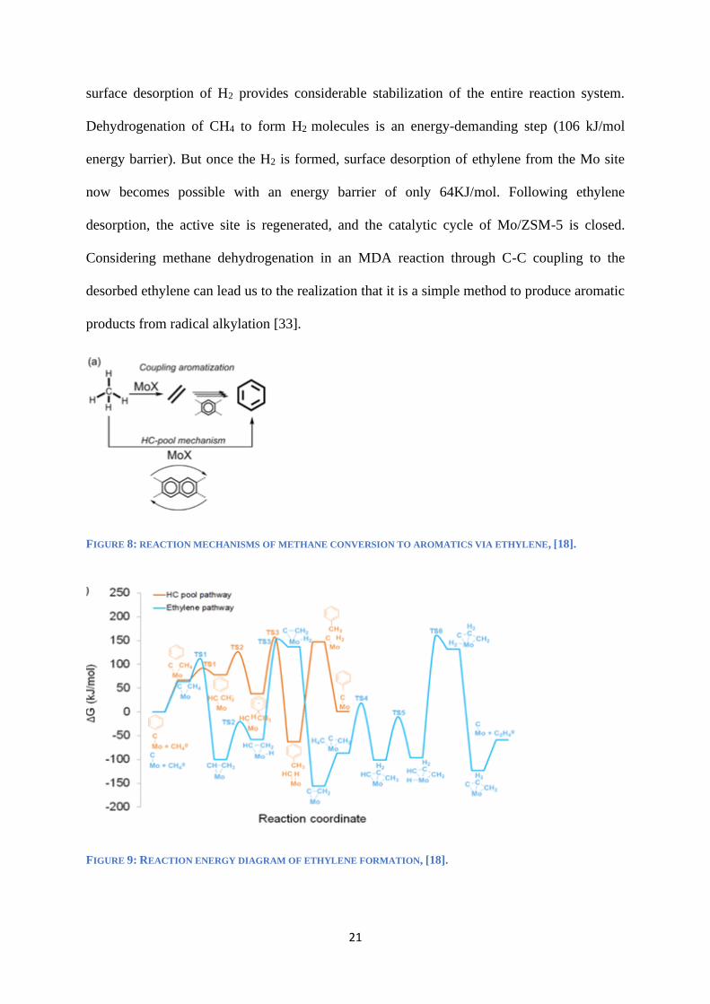
surface desorption of H2 provides considerable stabilization of the entire reaction system.
Dehydrogenation of CH4 to form H2 molecules is an energy-demanding step (106 kJ/mol
energy barrier). But once the H2 is formed, surface desorption of ethylene from the Mo site
now becomes possible with an energy barrier of only 64KJ/mol. Following ethylene
desorption, the active site is regenerated, and the catalytic cycle of Mo/ZSM-5 is closed.
Considering methane dehydrogenation in an MDA reaction through C-C coupling to the
desorbed ethylene can lead us to the realization that it is a simple method to produce aromatic
products from radical alkylation [33].
FIGURE 8: REACTION MECHANISMS OF METHANE CONVERSION TO AROMATICS VIA ETHYLENE, [18].
FIGURE 9: REACTION ENERGY DIAGRAM OF ETHYLENE FORMATION, [18].

22
Mass Diffusion of Aromatics
As already discussed, mesoporous zeolites such as ZSM-5 are prone to higher catalytic
activity and longer lifetime and better performance as compared to other traditional catalysts
[36]. The two main reasons for this superiority are the improved diffusivity of the substrate
molecules and improved access to active sites for better reactions. Diffusion is critical in mass
transfer during catalysis, product separation, and selectivity. For example, simulation research
on the diffusiveness of benzene in mesoporous H-ZSM-5 zeolite catalyst at 300K over pore
sizes of 20 Å is a stunning 1.7 ± 0.4 × 10⁻¹⁰ m2/s. These simulated experiments also give an
outlook that diffusion within the micropores and the external surfaces of the hierarchical
mesoporous H-ZSM-5 is dominant at low temperatures only, whereas diffusion along the
mesopores only becomes significantly enhanced at pyrolysis temperatures relevant to the
reaction [4]. See the figures below.
FIGURE 10: SUPERIMPOSITION OF BENZENE, MOLECULES DIFFUSING IN MESOPOROUS H-ZSM-5 ZEOLITE
WITH A PORE SIZE OF 20 Å AT 300K, [4].

23
FIGURE 11: SUPERIMPOSITION OF BENZENE, MOLECULES DIFFUSING IN MESOPOROUS H-ZSM-5 ZEOLITE
WITH A PORE SIZE OF 20 Å AT 700K, [4].
3.3 PARAMETERS FOR CATALYTIC PERFORMANCE
The performance and effectiveness of the zeolite catalyst Mo/ZSM-5 during the
methane dehydroaromatization (MDA) is influenced by several parameters that have been
explored at length by researchers in the field studies related of aromatization of methane. Most
parameters in catalyst action are usually responsible for the activation and deactivation of the
catalyst hence relatively tend to shape the performance path. In the case of Mo/ZSM-5,
performance is measured in terms of the total conversion rate for methane and resultant yields
of benzene, factors such as coking can be considered as impediments to the performance of
Mo/ZSM-5. For this section, we will evaluate important the effects of 5 main parameters on
Mo/ZSM-5 performance during methane dehydroaromatization (MDA). It is important to
remember that catalytic performance, in this case, involves the quantity of benzene yield from
total methane conversion and the content and condensation degree (C/H ratio) of the
carbonaceous deposits during say coking. The parameters include molybdenum content (Mo
content ranging from 1-10 wt. %), the reaction temperature (in the range of 720 °C -780 °C),
the space velocity (ranging from 405/h-1620/h), and the reaction time (ranging from 0.5-20 h).
Operating optimally, Mo/ZSM-5 catalysts generate up to 70% of aromatic selectivity and a
consequent total resultant methane conversion of up to 14% at 720 oC. The main challenge
with this process is the formation of carbonaceous by-products during methane

24
dehydroaromatization. A carbonaceous deposit affects catalytic performance. The contents of
the carbonaceous deposits depend on both the contents of Mo/ZSM-5 catalysts used and the
reaction condition (temperature, velocity, and reaction time).
Content/ composition of Molybdenum content in Mo/ZSM-5: According to Matus et al.
[24], the formation of carbonaceous deposits increases linearly as the molybdenum content in
Mo/ZSM-5 increases from 0-2 wt. % and thereafter remains relatively constant from 2-10 wt.
%. The table below reflects the effects of Mo content on the activity of Mo/ZSM-5 catalyst
studied in the methane DHA reaction.
Molybdenum content (wt. %) 1 2 5 10
Total methane conversion irrespective of products (%) 10.5 13.8 12.2 7.0
Methane conversion to benzene (%) 6.3 9.6 9.5 3.7
Benzene formation rate (μmolC6H6/(gMo·s)) 13.9 10.9 4.1 0.5 Table 5: Total methane conversion as a result of an increase in Mo content
This data indicates that total methane conversion as a result of an increase in Mo content
from 1-2 wt. %, while simultaneously, the rate of benzene conversion also grows as Mo content
increases from 1 to 2 to 5. Increase in Mo content from 5 wt. % to 10 wt. % results in a
substantial decline of both total methane conversion and benzene selectivity. This sharp decline
is due to the product additional carbonaceous deposits aside from the main hydrogen, and
benzene products wanted. These are carbon monoxide, ethylene, ethane, toluene, and
naphthalene. See the graph below.

25
FIGURE 12: EFFECT OF THE MOLYBDENUM CONTENT (1) AND THE CONTENT OF CARBONACEOUS DEPOSITS (2)
FOR THE MO/ZSM-5 CATALYSTS
Reaction time: reaction time affects the performance of the zeolite Mo/ZSM-5 catalyst by
altering the size of the zeolite micropore surface area. The specific pore volume and pore
surface area decrease after the catalyst has been on stream. Reaction time is a coupled effect
dependent on the Mo content in the zeolite. According to Matus et al. [24], 10 wt. % Mo content
receives the largest and most pronounced effect when considering reaction time. During an
MDA reaction, the surface area of zeolite Mo/ZSM-5 with Mo content of 2 wt. % decreases by
15% after 6 hours of reaction time. When the Mo content is increased to 10 wt. %, it results in
a huge decline in surface area by approximately 65%. When the reaction time is increased, the
surface area and pore volume continue to decrease. For example, experimental results show
that specific surface area of a 2% Mo/ZSM-5 sample decreased by 35% after being on stream
for 20 hours. See the figure below. Researchers argue that a decrease in pore volume and pore
surface area may be as a result of excessive and continuous carbonaceous deposit accumulation
on the pores during the reaction, thus effectively blocking the zeolite's micropores [24].

26
FIGURE 13: REACTION ACTIVITY OF 2% MO /ZSM-5 CATALYST IN THE DHA OF (REACTION CONDITIONS:
90%CH4, 10%AR, 810 /H, 720°C)
Space velocity: space velocity in catalysis refers to the rate at which gas is allowed to flow
through the reactor bed during a catalytic reaction. In general, an increase in the space velocity
(in this case, heated Argon gas flow rate) leads to an increase in carbonaceous deposits, which
in turn affects the performance of the catalysts. For example, assume that the space velocity is
increased from 405/h to 1620/h will grow by approximately 7.0 units. Similar to the methane
flow rate in an MDA reaction behaves in the same manner, although total rate is subjective to
reaction time.
The figure below summarizes the effect of the reaction temperature (T), reaction time
(t) and space velocity (V) on both the content of carbonaceous deposits (measured in wt. %)
and the position of exothermic effect maximum (TDTA) for the 2%Mo/ZSM-5 catalysts after
6 h on stream.

27
FIGURE 14: THE EFFECT OF EFFECT OF THE REACTION TEMPERATURE (T), REACTION TIME (T) AND SPACE
VELOCITY (V) ON BOTH THE CONTENT OF CARBONACEOUS DEPOSITS (MEASURED IN WT. %).
3.4 CARBON DEPOSITION SPECIES AND CATALYTIC DEACTIVATION
As discussed earlier, carbon deposits are by-products from processes such as methane
dehydroaromatization, which can result in catalyst deactivation and declining performance.
This section will examine these two application areas with consideration to the quantity weight
of carbon deposits under specific conditions using a comparative approach.
Carbon Deposition and Catalytic Deactivation during Methane Dehydroaromatization
According to Matus et al. [24], highly effective catalysts such as Mo/ZSM-5, which
provide for catalytic conversion of hydrocarbons into valuable products, are the key to
resolving problems linked to environmental protection as well as efficiency in resource
utilization. Methane dehydroaromatization into benzene, naphthalene, and other valuable
products is one such efficiency example. Mo/HZSM-5 zeolite catalyst provides up to 70%
selectivity in benzene synthesis during MDA and 14% methane conversion at temperatures of
720 °C. However, this process results in carbon deposits, which in some capacity assist in the

28
reaction but majorly contribute to catalytic deactivation. Studying the nature of the carbon
deposits formed during MDA is instrumental in preventing its formation as well as determining
the best intervention course for catalyst regeneration/activation. From the above information,
data and graphs, it was revealed that the properties of carbon deposits in Mo/ZSM-5 catalytic
MDA reaction is determined by; (1) the content of Molybdenum in Mo/ZSM-5 whereby the
amount of carbon deposits linearly increases as the composition on Mo increases up to a certain
degree (2wt%) after which it remains constant. (2) The reaction temperature which affects
oxidation and consequent carbon deposition. (3) The reaction time whereby the longer the
reaction time, the more the carbon deposition and the more deactivated the catalyst becomes.
(4) Finally, carbon deposition is also affected by the space velocity/ flow rate of argon in the
reaction, which, if increased, results in a consequent increase in carbon deposits in the active
sites of the zeolite catalysts are thereby deactivating it effectively. Contrary arguments hold
that consecutive mechanism of carbon deposit formation during MDA allows the active
catalysts in reaction to produce monoaromatics in higher quantities and higher concentrations
[30]. The figure below illustrates that, as the content of carbon deposits increases benzene
formation rate also increases.
FIGURE 15: CORRELATION BETWEEN ACTIVITIES OF MO/ZSM-5 VS. CD CONTENTS FORMED AFTER 6 H ON
STREAM. REACTION CONDITIONS: 90 VOL. % CH4 + 10 VOL. % AR, 810/H, 720°C.
29
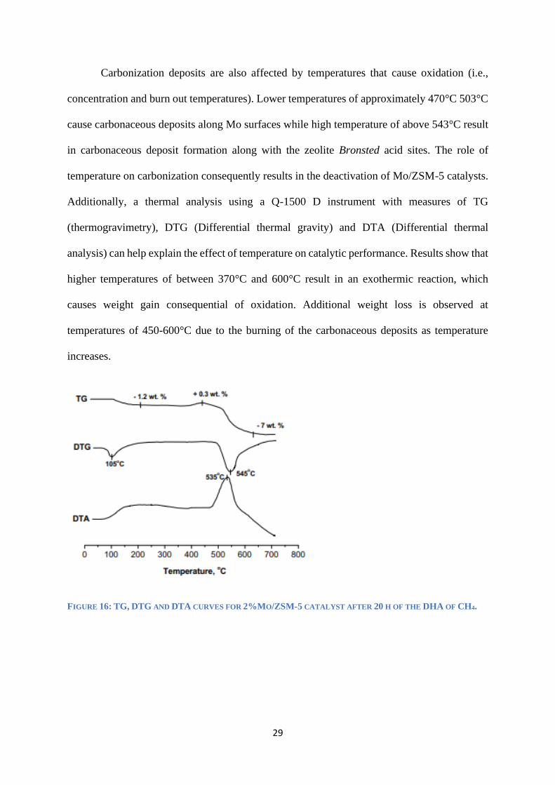
Carbonization deposits are also affected by temperatures that cause oxidation (i.e.,
concentration and burn out temperatures). Lower temperatures of approximately 470°C 503°C
cause carbonaceous deposits along Mo surfaces while high temperature of above 543°C result
in carbonaceous deposit formation along with the zeolite Bronsted acid sites. The role of
temperature on carbonization consequently results in the deactivation of Mo/ZSM-5 catalysts.
Additionally, a thermal analysis using a Q-1500 D instrument with measures of TG
(thermogravimetry), DTG (Differential thermal gravity) and DTA (Differential thermal
analysis) can help explain the effect of temperature on catalytic performance. Results show that
higher temperatures of between 370°C and 600°C result in an exothermic reaction, which
causes weight gain consequential of oxidation. Additional weight loss is observed at
temperatures of 450-600°C due to the burning of the carbonaceous deposits as temperature
increases.
FIGURE 16: TG, DTG AND DTA CURVES FOR 2%MO/ZSM-5 CATALYST AFTER 20 H OF THE DHA OF CH4.

30
4. REACTOR DESIGN
Major processes in engineering and other scientific-based research in physics and
chemistry are pegged on ubiquitous chemical reactions. The use of catalysts is integral in these
processes; hence process engineers in these processes must be in a position on how to design
not only the correct catalysts for the reactions but also the reactors required for the catalysis
process. A reactor is defined as a machine, structure, or apparatus that allows the control of
conditions ideal for a specific reaction process to occur optimally. There are several types of
reactors namely: bioreactors (which control reaction within a bio-reactive environment),
chemical reactors (which provide controlled chemical reactions), fusion reactors (contain and
regulate an atomic fusion reaction), fission reactors (contain and regulate an atomic fission
reaction), inductors, current limiting reactors (control motor current in varied frequency
drivers), and nuclear reactors (contain and control energy generated from a nuclear reaction).
Effective reactor designs combine material balance, kinetic rate expression, and energy
balance to achieve optimum reaction conditions as well as determine the ideal size of the
reactor. Material balance implies how any given reaction species are distributed in space and
time. Energy balance describes how temperature varies in space and time across the duration
of the reaction, and kinetic rate expression spells out how each reaction species is dependent
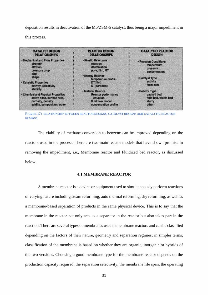
on concentration, temperature, and catalyst properties. Sterling catalytic reactor designs,
therefore, allow for astute integration of the reactor and catalysts. See the figure below that
describes the considerations in catalytic reactor designs. In recent times direct methane
aromatization has yielded positive results in the conversion of abundant natural gas into
valuable products such as benzene. The above section describes how rapid coking/ carbon
31
deposition results in deactivation of the Mo/ZSM-5 catalyst, thus being a major impediment in
this process.
FIGURE 17: RELATIONSHIP BETWEEN REACTOR DESIGNS, CATALYST DESIGNS AND CATALYTIC REACTOR
DESIGNS
The viability of methane conversion to benzene can be improved depending on the
reactors used in the process. There are two main reactor models that have shown promise in
removing the impediment, i.e., Membrane reactor and Fluidized bed reactor, as discussed
below.
4.1 MEMBRANE REACTOR
A membrane reactor is a device or equipment used to simultaneously perform reactions
of varying nature including steam reforming, auto thermal reforming, dry reforming, as well as
a membrane-based separation of products in the same physical device. This is to say that the
membrane in the reactor not only acts as a separator in the reactor but also takes part in the
reaction. There are several types of membranes used in membrane reactors and can be classified
depending on the factors of their nature, geometry and separation regimes; in simpler terms,
classification of the membrane is based on whether they are organic, inorganic or hybrids of
the two versions. Choosing a good membrane type for the membrane reactor depends on the
production capacity required, the separation selectivity, the membrane life span, the operating
32
conditions, the mechanical and chemical integrity subject to operating conditions, as well as
the cost. Membrane reactors are increasingly gaining popularity in the catalysis field as will be
discussed below. First, it is important to discuss the types of membranes in brief.
TYPES OF MEMBRANES
Membranes are broadly classified into two categories; that is, biological membranes and
synthetic membranes.
Biological membranes
These are easy to manufacture but are not widely applied due to many inherent disadvantages
culminating from limited underlying temperatures (should not exceed 100 °C), limited pH
range, hart to maintain (clean up), as well as, microbial attacks owing to their natural origin
Synthetic membranes
These are categorized into polymeric membranes and inorganic membranes:
Polymeric membranes: limited to a temperature of between 100 -300°C. All polymers can be
used as polymeric membranes if the underlying chemical and physical properties are relevant
to the reaction, i.e., its specific properties. Many industrial processes today involve high
temperatures which are why polymeric membranes are not preferred.
Inorganic membranes: these are manufactured from different materials such as ceramics,
carbon, silica, zeolites, oxides (titania, alumina, zirconia) palladium, silver and their alloys.
This makes the stable eve at high temperatures ranging from 300 – 800 ºC and others are stable
at 1000 ºC. Unlike polymeric and biological membranes, they possess high resistance to
physical and chemical degradation. Additional advantages include inertness to microbial
degradation, resistance to high pressures and easy cleanability after fouling, as well as, easy
catalytic activation. Disadvantages include high capital cost, low permeability, as well as,

33
difficulty of achieving high selectivity for the large-scale microporous membranes. The main
types of inorganic membranes include metal membranes, ceramic membranes, carbon
membranes, and zeolite membranes.
MEMBRANE REACTOR DESIGN FOR DMA
As we have discussed DMA involves a reaction that converts methane (CH4) to
hydrogen (H2) and aromatic benzene (C6H6) products. It is usually performed over
molybdenum (Mo) catalyst on zeolite support (e.g., HZSM-5 or ZSM-5) as shown below:
Step 1: 2CH4=C2H4+ 2H2
Step 2: 3C2H4=C6H6+3H2
However, this design results in low methane conversion due to high concentrations of
hydrogen produced in both reactions, as shown in the equations above. To overcome this
limitation, it is ideal for removing the excess hydrogen from the reactor. The membrane reactor
is ideal for this task due to its separation capabilities. As defined above, membrane reactors are
systems which typically enable process intensification and higher process efficiency by
combining a reactor and a separator into one unit. Methane conversion is thus higher in a
membrane reactor due to the selective removal of both product species through the membrane.
Without the membrane reactor, the equilibrium, shifts towards the reactants while using the
membrane reactor for DMA, equilibrium is pushed towards the products when hydrogen is
removed via the selective hydrogen membrane as shown in the figure below.
FIGURE 18: MEMBRANE REACTOR USING MO/HZSM-5, [10].

34
The main advantages of a membrane reactor in DMA include reduced downstream separation
and capital costs, as well as enhanced yields (higher conversion rates) and higher selectivity.
Challenges of the membrane reactor
The shell and tube membrane reactor design shown above in Figure 18 is subject to the
limitations underling coking discussed earlier in this paper. A newer improved model of the
same which accounts for coking is presented below.
Coking during DMA is assumed to be caused by ethylene formation from the molybdenum
carbide on the zeolite pores, thus blocking access to the BAS for methane (polyolefinic and
polyaromatic cokes). Oxygen and steam suppress coke formation [5] Oxygen also inhibits the
formation of molybdenum carbide [37]. The multifunctional membrane model shown above
makes this possible by employing two membranes in one system targeted at separating oxygen
from the air into the reaction zone and separating hydrogen from the reaction zone. The model
consists of three zones;
Reaction zone: this is where the feed methane is introduced and where the reactions
in the DMA take place.
Outer shell: here, helium gas (sweep gas) is introduced whose main task is to carry
away the separated hydrogen through the hydrogen-permeable membrane (M1).
Inner tube: this provides a base where air enters and the oxygen in air permeates via
the oxygen-permeable membrane (M2) into the reaction zone.
A simulation of the above model yielded the following results; by slow introduction of
oxygen via the oxygen-selective membrane, the catalyst deactivated within the same time span
as the original model however the deactivation was to a significantly lesser degree. In addition,
less coke was formed, and there was increased sensitivity. Coke production is decreased by

35
approximately 80% to 90% over several hours. The apparent drawback was that most of the
carbon in this process went to COx products (CO and CO2), as opposed to benzene.
4.2: FLUIDIZED BED REACTOR
Revolutionary fluid bed reactors have gained wide usage in many industrial processes,
especially those involving gas-solids reactions. The main advantage of fluid bed reactors
underlies its usage with numerous reaction gases including air, nitrogen, hydrogen, ammonia,
carbon dioxide, oxygen, argon, and steam among others; and is known to be tolerant for
temperatures reaching up to 1100 ºC. Some of these industrial processes include; oxidation of
metal powders, silicates, pigments, alumina silicates, carbon materials, organic substrates and
catalysts; reduction reactions for metal oxides, mixed oxides, hydroxides, silicon and silicon
compounds, ores, salts, silicates and alumina silicates, organic substances and catalysts; it is
also used for gas-gas reactions on fluidized catalysts for metal oxides, mixed oxides and
organic substances; used for gas to solid reactions in most chemical gas-solid reactions except
those involving hydrates; it is used for surface treatment, i.e., activation and passivation; used
for chemical coating of support materials with metal powders metal oxides, mixed oxides,
alumina silicates, carbon material, organic substances, and catalysts. This makes the fluidized
bed reactor especially attractive for DMA reactions over Mo/ZSM-5 catalyst.
FLUIDIZED BED REACTOR FOR METHANE DEHYDROAROMATIZATION
Generally, catalytic reactors are of two types; fixed bed reactors and fluidized bed
reactors. Research from a two decades ago had suggested that fixed bed reactors have a superior
advantage over fluidized bed reactors in that they provide easier catalyst regeneration and
replacement, can handle extremely high operation pressures, foster minimum wear of catalyst
and reaction equipment, have higher conversion efficiency, have lower pore diffusion rate and
can allow greater variability in alteration of reaction conditions [3]. However, advancements

36
in R&D over the past two decades have led to better-fluidized bed design in reaction processes
such as DMA/ MDA [33]. This constitutes used of fluidizable binder-free Mo/HZSM-5 catalyst
in the bed reactors that generated H2 for rapid regeneration of deactivated Mo/HZSM-5 catalyst
subject to coking limitation, as well as, dual-bed circulation systems that allow continuous
mixing and processing of Mo/HZSM-5 for greater efficiency and reaction stability [38].
FIGURE 19: DUAL-BED TYPE OF CIRCULATING FLUIDIZED BED REACTOR, [35].
An additional reason why this system is advantageous in that it can offer greater
flexibility when one requires to independently designing the capacity of each of its fluidized
beds in the system. This is to mean that the gas-solid contact time of each of its two beds can
independently be customized to suit the user's needs.
One major challenge however with all typical Mo/HZSM-5 catalyzed MDA reaction
systems is the unbalanced catalyst deactivation and regeneration rates, which make it difficult
to achieve the flexibility needed to realize a stably operable and continuous MDA reactor
design. Hydrogenation and hydrogenolysis reactions can be utilized to remove the
carbonaceous deposits that cause the catalyst to deactivate, provided hydrogen is present, and
the temperature range is maintained at a level that is workable for Mo/ZSM-5.
This process (i.e., coke removal by Hydrogenation in the presence of hydrogen from
deactivated Mo/HZSM-5) is very time-consuming. This high time-dependence of the CH4

37
concentration during H2-based regeneration of deactivated Mo/HZSM-5 sample at 1073 K is
shown in the figure below.
FIGURE 20: COKE REMOVAL USING HYDROGEN IN A FLUIDIZED BED REACTOR [29].
The sample in this graph was initially coked in a cyclic 5 min (CH4-5 min) and H2 feed
switch operation for 80 min (which represents the total cumulative CH4-feeding time). The
graph shows the slow regeneration feature of deactivated Mo/ZSM-5 catalyst [29]. Research
by Zhan-GuoZhang [38], shows that this challenge can be overcome altering the exposure time
and reaction condition to include longer periods of H2-regeneration (more than a few hours at
least) at conditions of temperature (1093 K), pressures 0.15 MPa and Hydrogen space velocity
(3,000 mL/g/h). This assists in the recovery of the benzene formation activity lost over a shorter
reaction period involving Mo/ZSM-5 at identical temperature, pressure and gas hourly space
velocities.
Advantages of Fluidized Bed Reactors over Membrane Reactors
Hydrogen and oxygen in heated conditions result in steam, which in turn suppresses
coke formation in both the reactor models. The degree of catalyst deactivation is also reduced

38
significantly under the prevailing conditions. Methane conversion curve overtime is higher for
a fixed-bed reactor (FR) than in a membrane reactor (MR) as shown in the figure below.
FIGURE 21: METHANE CONVERSION CURVE OVER TIME FOR A FIXED-BED REACTOR (FR) AND A MEMBRANE
REACTOR (MR).
Additional advantages of the fluidized bed reactor in comparison to the membrane
reactor include the following; it has simple standard components making it easier to design and
operate; it flexibly allows both batch and continuous reactions tailored to the user's needs; it
has a very high gas-solid contact area subject to gas velocity making reactions optimum; most
bed reactors have integrated filter and reversible flow cleaning systems that prevent particulate
emissions (membrane reactors are difficult to clean); finally the fluidized bed reactor shows
greater heat and mass transfer efficiency, higher efficiency in heating and cooling, excellent
product consistency, temperature stability, as well as lower operating costs, energy
consumption and manpower requirements in comparison to the membrane reactor [11, 28].

39
Conclusion
Methane dehydroaromatization (MDA) is a highly promising venture in natural gas
utilization/ exploitation. Essentially, Mo/HZSM-5 catalyzed MDA reaction provides an
effective path towards the production of non-petroleum aromatic products from methane,
which is the most abundant hydrocarbon in the planet. The fundamental aspect of gaining this
add-on value from methane lays on the synthesis or selection of a catalyst with suitable
performance and good mechanical stability for methane aromatization reactions. This paper
has focused mainly on molybdenum zeolites manly Mo/ZSM-5, Mo/C, and Mo/H-ZSM-5.
ZSM-5 is one of the aluminosilicate zeolites, constituent members of the pentasil zeolite
family. The chemical formula is NanAlnSi96–nO192•16H2O and is the primary focus of this
paper. Catalyst preparation and characterization are important in this respect as it results in
catalysts with the correct texture, attrition resistance, and shape for industrial application
processes such as MDA. The performance and effectiveness of the zeolite catalyst Mo/ZSM-5
during the methane dehydroaromatization (MDA) are influenced by several parameters that
have been explored at length by researchers in the field studies related of aromatization of
methane. These include molybdenum content, the reaction temperature, the space velocity, and
the reaction time. Additionally, carbon deposition/ carbonaceous deposits as a result of coking
have presented extreme performance challenges in this process. Suppression of external coke
formation has now become the center of focus for many researchers in this field. A
breakthrough in this research is the acid-catalyzed polycondensation on the external surface
sites of zeolite crystals, which reduces the risk of external coke formation. Additionally, the
silanation process based on large organosilane reagents has also proven highly efficacious in
eliminating the external acidic sites were coke and carbonaceous deposits tend to form along
with the transcendent HZSM-5 zeolite (Ding et al.,). The consequence of this silanation process
on the Mo/HZSM-5 catalyst was shown to be an improved catalyst activity and/or aromatic

40
selectivity. The type of reactor and reactor design selected also play an important role in the
effectiveness of the MDA process. More specifically, the types of reactor model chosen
whether membrane or bed reactor has a direct effect on the efficacy of the MDA process.
Thermal pyrolysis, catalytic pyrolysis as well as radical chain polymerizations, for example,
being three of the most common methods for coke formation, can be reduced or effectively
eliminated using a fluidized bed reactor with a dual-bed reactor system. This paper has
provided an in-depth understanding of the comparative role of Mo/ZSM-5 catalyst for CH4
dehydroaromatization process with an examination into its underlying affluent aspects such as
preparation, characterization, performance, structure, active site location, reaction parameters,
desorption and mass diffusion, as well as the catalytic reactor designs in use.

41
References
[1]. Anggoro, Didi Dwi, et al. "Effect of Co and Mo Loading by Impregnation and Ion
Exchange Methods on Morphological Properties of Zeolite Y Catalyst." Bulletin of Chemical
Reaction Engineering & Catalysis 11.1 (2016): 75-83.
[2]. Argauer, Robert J and Landolt, George R (1972) "Crystalline zeolite zsm-5 and method
of preparing the same" U.S. Patent 3,702,886.
[3]. Bartholomew, Calvin H., and William C. Hecker. "Catalytic reactor design." Chemical
Engineering. McGraw Hill Publication (1994): 70-75.
[4]. Bu, Lintao, et al. "Diffusion of aromatic hydrocarbons in hierarchical mesoporous H-
ZSM-5 zeolite." Catalysis Today 312 (2018): 73-81.
[5]. Cao, Zhengwen, et al. "Natural gas to fuels and chemicals: improved methane
aromatization in an oxygen‐permeable membrane reactor." Angewandte Chemie International
Edition 52.51 (2013): 13794-13797.
[6]. Chandrasekhar, Sathy, and P. N. Pramada. "Microwave assisted synthesis of zeolite A
from metakaolin." Microporous and Mesoporous Materials 108.1-3 (2008): 152-161.
[7]. Choi, Jae-Soon, et al. "Structural evolution of molybdenum carbides in hot aqueous
environments and impact on low-temperature hydroprocessing of acetic acid." Catalysts 5.1
(2015): 406-423.
[8]. Deraz, N. M. "The importance of catalyst preparation." J Ind Environ Chem. 2018; 2
(1): 16 18.2 (2018).
[9]. Ding, Weiping, George D. Meitzner, and Enrique Iglesia. "The effects of silanation of
external acid sites on the structure and catalytic behavior of Mo/H–ZSM-5." Journal of
Catalysis 206.1 (2002): 14-22.

42
[10]. Fouty, Nicholas, Juan Carrasco, and Fernando Lima. "Modeling and Design
Optimization of Multifunctional Membrane Reactors for Direct Methane Aromatization."
Membranes 7.3 (2017): 48.
[11]. Gallucci, Fausto, Angelo Basile, and Faisal Ibney Hai. "Introduction-A review of
membrane reactors." (2011): 1.
[12]. Haber, Jerzy, Jochen H. Block, and Bernard Delmon. "Methods and Procedures for
Catalyst Characterization." Handbook of Heterogeneous Catalysis: Online (2008): 1230-1258.
[13]. Ji, Yajun, Honghui Yang, and Wei Yan. "Strategies to enhance the catalytic
performance of ZSM-5 zeolite in hydrocarbon cracking: A review." Catalysts 7.12 (2017): 367.
[14]. Julian, Ignacio, et al. "Non-oxidative methane conversion in microwave-assisted
structured reactors." Chemical Engineering Journal 377 (2019): 119764.
[15]. Kosinov, Nikolay, et al. "Methane dehydroaromatization by Mo/HZSM-5: mono-or
bifunctional catalysis?" ACS Catalysis 7.1 (2016): 520-529.
[16]. Kosinov, Nikolay, et al. "Reversible Nature of Coke Formation on Mo/ZSM‐5 Methane
Dehydroaromatization Catalysts." Angewandte Chemie International Edition 58.21 (2019):
7068-7072.
[17]. Leofanti, G., et al. "Catalyst characterization: characterization techniques." Catalysis
today 34.3-4 (1997): 307-327.
[18]. Li, Guanna, et al. "Structure and Reactivity of the Mo/ZSM-5 Dehydroaromatization
Catalyst: An Operando Computational Study." ACS Catalysis 9.9 (2019): 8731-8737.
[19]. Li, Jianwei, Jun Li, and Qingshan Zhu. "Carbon deposition and catalytic deactivation
during CO2 reforming of CH4 over Co/MgO catalyst." Chinese Journal of Chemical
Engineering 26.11 (2018): 2344-2350.

43
[20]. Li, Wei, et al. "The location, structure, and role of MoOx and MoCy species in Mo/H-
ZSM-5 catalysts for methane aromatization." Studies in Surface Science and Catalysis. Vol.
130. Elsevier, 2000. 3621-3626.
[21]. Liu, Zhendong, et al. "Continuous flow synthesis of ZSM-5 zeolite on the order of
seconds." Proceedings of the National Academy of Sciences 113.50 (2016): 14267-14271.
[22]. Ma, Zhen, and Francisco Zaera. "Characterization of heterogeneous catalysts." Surface
and Nanomolecular Catalysis (2006): 1-37.
[23]. Mannei, Emna, et al. "Solid–state ion exchange of molybdenum (VI) acetylacetonate
into ZSM-5 zeolite." Thermochimica Acta 652 (2017): 150-159.
[24]. Matus, E. V., et al. "Deactivation and regeneration of Mo/ZSM-5 catalysts for methane
dehydroaromatization." Eurasian Chemico-Technological Journal 12.1 (2010): 1-8.
[25]. Munnik, Peter, P+etra E. de Jongh, and Krijn P. de Jong. "Recent developments in the
synthesis of supported catalysts." Chemical reviews 115.14 (2015): 6687-6718.
[26]. Pawar, Vivek, et al. "Study of short-term catalyst deactivation due to carbon deposition
during biogas dry reforming on supported Ni catalyst." Energy & Fuels 29.12 (2015): 8047-
8052.
[27]. Rostrup-Nielsen, J. R., and J. Bøgild Hansen. "Steam reforming for fuel cells." Fuel
Cells: Technologies for Fuel Processing. Elsevier, 2011. 49-71.
[28]. Son, Seong Yong, Dong Hyun Lee, and Sang Done Kim. "Effect of uniformity of gas
distribution on fluidization characteristics in conical gas fluidized beds." Studies in surface
science and catalysis (2006): 557-560.
[29]. Song, Y., Zhang, Q., Xu, Y., Zhang, Y., Matsuoka, K., & Zhang, Z. G. (2017). Coke
accumulation and deactivation behavior of microzeolite-based Mo/HZSM-5 in the non-
oxidative methane aromatization under cyclic CH4-H2 feed switch mode. Applied Catalysis
A: General, 530, 12-20.

44
[30]. Tempelman, Christiaan HL, and Emiel JM Hensen. "On the deactivation of Mo/HZSM-
5 in the methane dehydroaromatization reaction." Applied Catalysis B: Environmental 176
(2015): 731-739.
[31]. Velebná, Klaudia, et al. "The influence of molybdenum loading on activity of ZSM-5
zeolite in dehydroaromatization of methane." Microporous and Mesoporous Materials 212
(2015): 146-155.
[32]. Wang, Dingjun, Jack H. Lunsford, and Michael P. Rosynek. "Catalytic conversion of
methane to benzene over Mo/ZSM-5." Topics in Catalysis 3.3-4 (1996): 289-297.
[33]. Wong, Kae S., et al. "Methane aromatisation based upon elementary steps: Kinetic and
catalyst descriptors." Microporous and Mesoporous Materials 164 (2012): 302-312.
[34]. Wang, Shengnian, and Yuxin Wang. "Synthesis of hierarchical zeolites by solid state
crystallization of aluminosilicate nanogels." U.S. Patent No. 10,343,926. 9 Jul. 2019.
[35]. Yan, Peng, et al. "Development of a CH4 dehydroaromatization–catalyst regeneration
fluidized bed system." Chinese Journal of Chemical Engineering 26.9 (2018): 1928-1936.
[36]. Yu, Weiting, et al. "Theoretical and experimental studies of C–C versus C–O bond
scission of ethylene glycol reaction pathways via metal-modified molybdenum carbides." ACS
Catalysis 4.5 (2014): 1409-1418.
[37]. Yuan, Shandong, et al. "The effect of oxygen on the aromatization of methane over the
Mo/HZSM‐5 catalyst." Catalysis letters 63.1-2 (1999): 73-77.
[38]. Zhang, Zhan-Guo. "Process, reactor and catalyst design: Towards application of direct
conversion of methane to aromatics under nonoxidative conditions." Carbon Resources
Conversion (2019).
[39]. Zhou, Ming, Ali A. Rownaghi, and Jonas Hedlund. "Synthesis of mesoporous ZSM-5
zeolite crystals by conventional hydrothermal treatment." RSC advances 3.36 (2013): 15596-
15599.