dynamic routing guide documentation...3.6.11 dumbbell. . . . . . . . . . . . . . . . . . . . . . . ....
TRANSCRIPT

Ultra Messaging (Version 6.11.1)
Dynamic Routing GuideCopyright (C) 2004-2018, Informatica Corporation. All Rights Reserved.


Contents
1 Introduction 5
1.1 DRO Features . . . . . . . . . . . . . . . . . . . . . . . . . . . . . . . . . . . . . . . . . . . . . . 5
2 DRO Architecture 7
2.1 UM Router Portals . . . . . . . . . . . . . . . . . . . . . . . . . . . . . . . . . . . . . . . . . . . . 7
2.2 Topic Resolution Domains . . . . . . . . . . . . . . . . . . . . . . . . . . . . . . . . . . . . . . . . 8
2.3 Proxy Sources and Proxy Receivers . . . . . . . . . . . . . . . . . . . . . . . . . . . . . . . . . . . 8
2.4 Routing . . . . . . . . . . . . . . . . . . . . . . . . . . . . . . . . . . . . . . . . . . . . . . . . . . 9
3 UM Router Concepts 11
3.1 Basic UM Router Operation . . . . . . . . . . . . . . . . . . . . . . . . . . . . . . . . . . . . . . . 11
3.1.1 Interest and Use Queries . . . . . . . . . . . . . . . . . . . . . . . . . . . . . . . . . . . . 12
3.1.2 UM Router Keepalive . . . . . . . . . . . . . . . . . . . . . . . . . . . . . . . . . . . . . . 13
3.1.3 Final Advertisements . . . . . . . . . . . . . . . . . . . . . . . . . . . . . . . . . . . . . . 13
3.1.4 More About Proxy Sources and Receivers . . . . . . . . . . . . . . . . . . . . . . . . . . . 13
3.2 Multi-Hop Forwarding . . . . . . . . . . . . . . . . . . . . . . . . . . . . . . . . . . . . . . . . . . 14
3.3 Routing Wildcard Receivers . . . . . . . . . . . . . . . . . . . . . . . . . . . . . . . . . . . . . . . 15
3.4 Forwarding Costs . . . . . . . . . . . . . . . . . . . . . . . . . . . . . . . . . . . . . . . . . . . . 16
3.5 UM Router Routing . . . . . . . . . . . . . . . . . . . . . . . . . . . . . . . . . . . . . . . . . . . 16
3.6 Routing Topologies . . . . . . . . . . . . . . . . . . . . . . . . . . . . . . . . . . . . . . . . . . . 17
3.6.1 Direct Link . . . . . . . . . . . . . . . . . . . . . . . . . . . . . . . . . . . . . . . . . . . . 17
3.6.2 Single Link . . . . . . . . . . . . . . . . . . . . . . . . . . . . . . . . . . . . . . . . . . . . 17
3.6.3 Parallel Links . . . . . . . . . . . . . . . . . . . . . . . . . . . . . . . . . . . . . . . . . . 18
3.6.4 Loops . . . . . . . . . . . . . . . . . . . . . . . . . . . . . . . . . . . . . . . . . . . . . . 18
3.6.5 Loop and Spur . . . . . . . . . . . . . . . . . . . . . . . . . . . . . . . . . . . . . . . . . . 19
3.6.6 Loop with Centralized TRD . . . . . . . . . . . . . . . . . . . . . . . . . . . . . . . . . . . 19
3.6.7 with centralized TRD . . . . . . . . . . . . . . . . . . . . . . . . . . . . . . . . . . . . . . 20
3.6.8 Star with Centralized UM Router . . . . . . . . . . . . . . . . . . . . . . . . . . . . . . . . 20
3.6.9 Mesh . . . . . . . . . . . . . . . . . . . . . . . . . . . . . . . . . . . . . . . . . . . . . . 21
3.6.10 Palm Tree . . . . . . . . . . . . . . . . . . . . . . . . . . . . . . . . . . . . . . . . . . . . 21
3.6.11 Dumbbell . . . . . . . . . . . . . . . . . . . . . . . . . . . . . . . . . . . . . . . . . . . . 22
3.7 Unsupported Configurations . . . . . . . . . . . . . . . . . . . . . . . . . . . . . . . . . . . . . . . 22

4 CONTENTS
3.8 UM Feature Compatibility . . . . . . . . . . . . . . . . . . . . . . . . . . . . . . . . . . . . . . . . 23
4 UM Router Implementation 25
4.1 UM Router Configuration Overview . . . . . . . . . . . . . . . . . . . . . . . . . . . . . . . . . . . 25
4.2 Creating Applications for UM Router Compatibility . . . . . . . . . . . . . . . . . . . . . . . . . . . 25
4.2.1 Naming and Identification . . . . . . . . . . . . . . . . . . . . . . . . . . . . . . . . . . . . 25
4.2.2 Portal Costs . . . . . . . . . . . . . . . . . . . . . . . . . . . . . . . . . . . . . . . . . . . 26
4.2.3 Access Control Lists (ACL) . . . . . . . . . . . . . . . . . . . . . . . . . . . . . . . . . . . 26
4.2.4 Timers and Intervals . . . . . . . . . . . . . . . . . . . . . . . . . . . . . . . . . . . . . . . 29
4.2.5 Multicast Immediate Messaging Considerations . . . . . . . . . . . . . . . . . . . . . . . . 29
4.2.6 Persistence Over the UM Router . . . . . . . . . . . . . . . . . . . . . . . . . . . . . . . . 29
4.2.7 Late Join and Off-Transport Recovery . . . . . . . . . . . . . . . . . . . . . . . . . . . . . 30
4.2.8 Topic Resolution Reliability . . . . . . . . . . . . . . . . . . . . . . . . . . . . . . . . . . . 31
4.2.9 BOS and EOS Behavior Over the UM Router . . . . . . . . . . . . . . . . . . . . . . . . . . 31
4.3 Topology Configuration Examples . . . . . . . . . . . . . . . . . . . . . . . . . . . . . . . . . . . . 31
4.3.1 Direct Link Configuration . . . . . . . . . . . . . . . . . . . . . . . . . . . . . . . . . . . . 31
4.3.2 Peer Link Configuration . . . . . . . . . . . . . . . . . . . . . . . . . . . . . . . . . . . . . 33
4.3.3 Transit TRD Link Configuration . . . . . . . . . . . . . . . . . . . . . . . . . . . . . . . . . 34
4.3.4 Parallel Links Configuration . . . . . . . . . . . . . . . . . . . . . . . . . . . . . . . . . . . 36
4.3.5 Loop and Spur Configuration . . . . . . . . . . . . . . . . . . . . . . . . . . . . . . . . . . 38
4.3.6 Star Configuration . . . . . . . . . . . . . . . . . . . . . . . . . . . . . . . . . . . . . . . . 42
4.3.7 Mesh Configuration . . . . . . . . . . . . . . . . . . . . . . . . . . . . . . . . . . . . . . . 43
4.4 Using UM Configuration Files with the UM Router . . . . . . . . . . . . . . . . . . . . . . . . . . . 48
4.4.1 Setting Individual Endpoint Options . . . . . . . . . . . . . . . . . . . . . . . . . . . . . . . 48
4.4.2 UM Router and UM XML Configuration Use Cases . . . . . . . . . . . . . . . . . . . . . . . 49
4.4.3 Sample Configuration . . . . . . . . . . . . . . . . . . . . . . . . . . . . . . . . . . . . . . 50
4.4.4 XML UM Configuration File . . . . . . . . . . . . . . . . . . . . . . . . . . . . . . . . . . . 50
4.4.5 XML UM Router Configuration File . . . . . . . . . . . . . . . . . . . . . . . . . . . . . . . 51
4.5 Running the UM Router Daemon . . . . . . . . . . . . . . . . . . . . . . . . . . . . . . . . . . . . 51
4.5.1 tnwgd . . . . . . . . . . . . . . . . . . . . . . . . . . . . . . . . . . . . . . . . . . . . . . 52
5 XML Configuration Reference 53
5.1 File Structure . . . . . . . . . . . . . . . . . . . . . . . . . . . . . . . . . . . . . . . . . . . . . . . 53
5.2 Elements Reference . . . . . . . . . . . . . . . . . . . . . . . . . . . . . . . . . . . . . . . . . . . 55
5.2.1 <tnw-gateway> . . . . . . . . . . . . . . . . . . . . . . . . . . . . . . . . . . . . . . . . . 55
5.2.2 <daemon> . . . . . . . . . . . . . . . . . . . . . . . . . . . . . . . . . . . . . . . . . . . 56
5.2.3 <name> . . . . . . . . . . . . . . . . . . . . . . . . . . . . . . . . . . . . . . . . . . . . 56
5.2.4 <log> . . . . . . . . . . . . . . . . . . . . . . . . . . . . . . . . . . . . . . . . . . . . . . 57
5.2.5 <uid> . . . . . . . . . . . . . . . . . . . . . . . . . . . . . . . . . . . . . . . . . . . . . . 57
5.2.6 <gid> . . . . . . . . . . . . . . . . . . . . . . . . . . . . . . . . . . . . . . . . . . . . . . 58
5.2.7 <pidfile> . . . . . . . . . . . . . . . . . . . . . . . . . . . . . . . . . . . . . . . . . . . . 58

CONTENTS 5
5.2.8 <lbm-license-file> . . . . . . . . . . . . . . . . . . . . . . . . . . . . . . . . . . . . . . . 59
5.2.9 <topicmap/> . . . . . . . . . . . . . . . . . . . . . . . . . . . . . . . . . . . . . . . . . . 59
5.2.10 <patternmap/> . . . . . . . . . . . . . . . . . . . . . . . . . . . . . . . . . . . . . . . . . 60
5.2.11 <monitor> . . . . . . . . . . . . . . . . . . . . . . . . . . . . . . . . . . . . . . . . . . . 61
5.2.12 <transport-module/> . . . . . . . . . . . . . . . . . . . . . . . . . . . . . . . . . . . . . . 61
5.2.13 <format-module/> . . . . . . . . . . . . . . . . . . . . . . . . . . . . . . . . . . . . . . . 62
5.2.14 <web-monitor> . . . . . . . . . . . . . . . . . . . . . . . . . . . . . . . . . . . . . . . . . 62
5.2.15 <daemon-monitor> . . . . . . . . . . . . . . . . . . . . . . . . . . . . . . . . . . . . . . . 63
5.2.16 <remote-snapshot-request> . . . . . . . . . . . . . . . . . . . . . . . . . . . . . . . . . . 64
5.2.17 <remote-config-changes-request> . . . . . . . . . . . . . . . . . . . . . . . . . . . . . . . 64
5.2.18 <xml-config> . . . . . . . . . . . . . . . . . . . . . . . . . . . . . . . . . . . . . . . . . . 65
5.2.19 <route-info> . . . . . . . . . . . . . . . . . . . . . . . . . . . . . . . . . . . . . . . . . . 65
5.2.20 <route-recalculation> . . . . . . . . . . . . . . . . . . . . . . . . . . . . . . . . . . . . . 66
5.2.21 <portals> . . . . . . . . . . . . . . . . . . . . . . . . . . . . . . . . . . . . . . . . . . . . 67
5.2.22 <endpoint> . . . . . . . . . . . . . . . . . . . . . . . . . . . . . . . . . . . . . . . . . . . 67
5.2.23 <domain-id> . . . . . . . . . . . . . . . . . . . . . . . . . . . . . . . . . . . . . . . . . . 68
5.2.24 <cost> . . . . . . . . . . . . . . . . . . . . . . . . . . . . . . . . . . . . . . . . . . . . . 68
5.2.25 <source-deletion-delay> . . . . . . . . . . . . . . . . . . . . . . . . . . . . . . . . . . . . 69
5.2.26 <max-queue> . . . . . . . . . . . . . . . . . . . . . . . . . . . . . . . . . . . . . . . . . 70
5.2.27 <lbm-config> . . . . . . . . . . . . . . . . . . . . . . . . . . . . . . . . . . . . . . . . . . 70
5.2.28 <lbm-attributes> . . . . . . . . . . . . . . . . . . . . . . . . . . . . . . . . . . . . . . . . 71
5.2.29 <option/> . . . . . . . . . . . . . . . . . . . . . . . . . . . . . . . . . . . . . . . . . . . . 71
5.2.30 <acl> . . . . . . . . . . . . . . . . . . . . . . . . . . . . . . . . . . . . . . . . . . . . . . 72
5.2.31 <inbound> . . . . . . . . . . . . . . . . . . . . . . . . . . . . . . . . . . . . . . . . . . . 73
5.2.32 <outbound> . . . . . . . . . . . . . . . . . . . . . . . . . . . . . . . . . . . . . . . . . . 73
5.2.33 <ace> . . . . . . . . . . . . . . . . . . . . . . . . . . . . . . . . . . . . . . . . . . . . . 74
5.2.34 <topic> . . . . . . . . . . . . . . . . . . . . . . . . . . . . . . . . . . . . . . . . . . . . . 75
5.2.35 <pcre-pattern> . . . . . . . . . . . . . . . . . . . . . . . . . . . . . . . . . . . . . . . . . 75
5.2.36 <regex-pattern> . . . . . . . . . . . . . . . . . . . . . . . . . . . . . . . . . . . . . . . . 76
5.2.37 <transport/> . . . . . . . . . . . . . . . . . . . . . . . . . . . . . . . . . . . . . . . . . . 76
5.2.38 <source-ip/> . . . . . . . . . . . . . . . . . . . . . . . . . . . . . . . . . . . . . . . . . . 77
5.2.39 <multicast-group/> . . . . . . . . . . . . . . . . . . . . . . . . . . . . . . . . . . . . . . . 77
5.2.40 <udp-source-port/> . . . . . . . . . . . . . . . . . . . . . . . . . . . . . . . . . . . . . . 78
5.2.41 <udp-destination-port/> . . . . . . . . . . . . . . . . . . . . . . . . . . . . . . . . . . . . 78
5.2.42 <tcp-source-port/> . . . . . . . . . . . . . . . . . . . . . . . . . . . . . . . . . . . . . . . 79
5.2.43 <xport-id/> . . . . . . . . . . . . . . . . . . . . . . . . . . . . . . . . . . . . . . . . . . . 79
5.2.44 <topic-resolution> . . . . . . . . . . . . . . . . . . . . . . . . . . . . . . . . . . . . . . . 80
5.2.45 <initial-request/> . . . . . . . . . . . . . . . . . . . . . . . . . . . . . . . . . . . . . . . . 80
5.2.46 <topic-use-query> . . . . . . . . . . . . . . . . . . . . . . . . . . . . . . . . . . . . . . . 81
5.2.47 <rate-limit/> . . . . . . . . . . . . . . . . . . . . . . . . . . . . . . . . . . . . . . . . . . 82

6 CONTENTS
5.2.48 <pattern-use-query> . . . . . . . . . . . . . . . . . . . . . . . . . . . . . . . . . . . . . . 83
5.2.49 <remote-topic-interest> . . . . . . . . . . . . . . . . . . . . . . . . . . . . . . . . . . . . 83
5.2.50 <remote-pattern-interest> . . . . . . . . . . . . . . . . . . . . . . . . . . . . . . . . . . . 84
5.2.51 <domain-route> . . . . . . . . . . . . . . . . . . . . . . . . . . . . . . . . . . . . . . . . 85
5.2.52 <remote-topic/> . . . . . . . . . . . . . . . . . . . . . . . . . . . . . . . . . . . . . . . . 85
5.2.53 <remote-pattern/> . . . . . . . . . . . . . . . . . . . . . . . . . . . . . . . . . . . . . . . 86
5.2.54 <source-context-name> . . . . . . . . . . . . . . . . . . . . . . . . . . . . . . . . . . . . 87
5.2.55 <receiver-context-name> . . . . . . . . . . . . . . . . . . . . . . . . . . . . . . . . . . . 87
5.2.56 <sqn-window/> . . . . . . . . . . . . . . . . . . . . . . . . . . . . . . . . . . . . . . . . . 88
5.2.57 <context-query/> . . . . . . . . . . . . . . . . . . . . . . . . . . . . . . . . . . . . . . . . 88
5.2.58 <peer> . . . . . . . . . . . . . . . . . . . . . . . . . . . . . . . . . . . . . . . . . . . . . 89
5.2.59 <sourcemap/> . . . . . . . . . . . . . . . . . . . . . . . . . . . . . . . . . . . . . . . . . 90
5.2.60 <tcp> . . . . . . . . . . . . . . . . . . . . . . . . . . . . . . . . . . . . . . . . . . . . . . 90
5.2.61 <interface> . . . . . . . . . . . . . . . . . . . . . . . . . . . . . . . . . . . . . . . . . . . 91
5.2.62 <listen-port> . . . . . . . . . . . . . . . . . . . . . . . . . . . . . . . . . . . . . . . . . . 91
5.2.63 <receive-buffer> . . . . . . . . . . . . . . . . . . . . . . . . . . . . . . . . . . . . . . . . 92
5.2.64 <send-buffer> . . . . . . . . . . . . . . . . . . . . . . . . . . . . . . . . . . . . . . . . . 92
5.2.65 <keepalive/> . . . . . . . . . . . . . . . . . . . . . . . . . . . . . . . . . . . . . . . . . . 93
5.2.66 <nodelay/> . . . . . . . . . . . . . . . . . . . . . . . . . . . . . . . . . . . . . . . . . . . 94
5.2.67 <compression> . . . . . . . . . . . . . . . . . . . . . . . . . . . . . . . . . . . . . . . . . 94
5.2.68 <tls> . . . . . . . . . . . . . . . . . . . . . . . . . . . . . . . . . . . . . . . . . . . . . . 95
5.2.69 <certificate> . . . . . . . . . . . . . . . . . . . . . . . . . . . . . . . . . . . . . . . . . . 95
5.2.70 <certificate-key> . . . . . . . . . . . . . . . . . . . . . . . . . . . . . . . . . . . . . . . . 96
5.2.71 <certificate-key-password> . . . . . . . . . . . . . . . . . . . . . . . . . . . . . . . . . . 96
5.2.72 <trusted-certificates> . . . . . . . . . . . . . . . . . . . . . . . . . . . . . . . . . . . . . 97
5.2.73 <cipher-suites> . . . . . . . . . . . . . . . . . . . . . . . . . . . . . . . . . . . . . . . . . 98
5.2.74 <companion> . . . . . . . . . . . . . . . . . . . . . . . . . . . . . . . . . . . . . . . . . 98
5.2.75 <address> . . . . . . . . . . . . . . . . . . . . . . . . . . . . . . . . . . . . . . . . . . . 99
5.2.76 <port> . . . . . . . . . . . . . . . . . . . . . . . . . . . . . . . . . . . . . . . . . . . . . 99
5.2.77 <single-tcp> . . . . . . . . . . . . . . . . . . . . . . . . . . . . . . . . . . . . . . . . . . 100
5.2.78 <initiator> . . . . . . . . . . . . . . . . . . . . . . . . . . . . . . . . . . . . . . . . . . . 101
5.2.79 <acceptor> . . . . . . . . . . . . . . . . . . . . . . . . . . . . . . . . . . . . . . . . . . . 101
5.2.80 <max-datagram> . . . . . . . . . . . . . . . . . . . . . . . . . . . . . . . . . . . . . . . . 102
5.2.81 <smart-batch> . . . . . . . . . . . . . . . . . . . . . . . . . . . . . . . . . . . . . . . . . 102
5.2.82 <batching> . . . . . . . . . . . . . . . . . . . . . . . . . . . . . . . . . . . . . . . . . . . 103
5.2.83 <min-length> . . . . . . . . . . . . . . . . . . . . . . . . . . . . . . . . . . . . . . . . . . 103
5.2.84 <batch-interval> . . . . . . . . . . . . . . . . . . . . . . . . . . . . . . . . . . . . . . . . 104
5.2.85 <gateway-keepalive/> . . . . . . . . . . . . . . . . . . . . . . . . . . . . . . . . . . . . . 104
5.3 Deprecated Elements . . . . . . . . . . . . . . . . . . . . . . . . . . . . . . . . . . . . . . . . . . 105
5.3.1 <propagation-delay/> . . . . . . . . . . . . . . . . . . . . . . . . . . . . . . . . . . . . . 105

CONTENTS 7
5.3.2 <late-join/> . . . . . . . . . . . . . . . . . . . . . . . . . . . . . . . . . . . . . . . . . . . 106
5.3.3 <topic-purge/> . . . . . . . . . . . . . . . . . . . . . . . . . . . . . . . . . . . . . . . . . 106
5.3.4 <topic-interest-generate/> . . . . . . . . . . . . . . . . . . . . . . . . . . . . . . . . . . . 107
5.3.5 <topic-domain-activity/> . . . . . . . . . . . . . . . . . . . . . . . . . . . . . . . . . . . . 108
5.3.6 <pattern-purge/> . . . . . . . . . . . . . . . . . . . . . . . . . . . . . . . . . . . . . . . . 108
5.3.7 <pattern-interest-generate/> . . . . . . . . . . . . . . . . . . . . . . . . . . . . . . . . . . 109
5.3.8 <pattern-domain-activity/> . . . . . . . . . . . . . . . . . . . . . . . . . . . . . . . . . . . 109
5.3.9 <topic-use-check/> . . . . . . . . . . . . . . . . . . . . . . . . . . . . . . . . . . . . . . . 110
5.3.10 <pattern-use-check/> . . . . . . . . . . . . . . . . . . . . . . . . . . . . . . . . . . . . . 110
5.3.11 <publishing-interval> . . . . . . . . . . . . . . . . . . . . . . . . . . . . . . . . . . . . . . 111
5.3.12 <group> . . . . . . . . . . . . . . . . . . . . . . . . . . . . . . . . . . . . . . . . . . . . 112
5.4 UM Router Configuration DTD . . . . . . . . . . . . . . . . . . . . . . . . . . . . . . . . . . . . . . 112
6 UM Router Daemon Statistics 119
6.1 UM Router Daemon Statistics Structures . . . . . . . . . . . . . . . . . . . . . . . . . . . . . . . . 119
6.1.1 UM Router Daemon Statistics Byte Swapping . . . . . . . . . . . . . . . . . . . . . . . . . 119
6.1.2 UM Router Daemon Statistics String Buffers . . . . . . . . . . . . . . . . . . . . . . . . . . 120
6.2 UM Router Daemon Statistics Configuration . . . . . . . . . . . . . . . . . . . . . . . . . . . . . . 120
6.3 UM Router Daemon Statistics Requests . . . . . . . . . . . . . . . . . . . . . . . . . . . . . . . . 121
7 UM Router Monitoring 123
7.1 Router Web Monitor . . . . . . . . . . . . . . . . . . . . . . . . . . . . . . . . . . . . . . . . . . . 123
7.1.1 Main Page . . . . . . . . . . . . . . . . . . . . . . . . . . . . . . . . . . . . . . . . . . . . 123
7.1.2 Endpoint Portal Page . . . . . . . . . . . . . . . . . . . . . . . . . . . . . . . . . . . . . . 124
7.1.3 Peer Portal Page . . . . . . . . . . . . . . . . . . . . . . . . . . . . . . . . . . . . . . . . 128
7.1.4 Topology Info Page . . . . . . . . . . . . . . . . . . . . . . . . . . . . . . . . . . . . . . . 133
7.1.5 Path Info . . . . . . . . . . . . . . . . . . . . . . . . . . . . . . . . . . . . . . . . . . . . . 134
7.2 UM Router Log Messages . . . . . . . . . . . . . . . . . . . . . . . . . . . . . . . . . . . . . . . . 135
7.2.1 UM Router Rolling Logs . . . . . . . . . . . . . . . . . . . . . . . . . . . . . . . . . . . . . 135
7.2.2 Important UM Router Log Messages . . . . . . . . . . . . . . . . . . . . . . . . . . . . . . 135
7.3 UM Router Transport Stats . . . . . . . . . . . . . . . . . . . . . . . . . . . . . . . . . . . . . . . 136
8 UM Router Glossary 137
9 Comparison to Pre-6.0 UM Gateway 139
9.1 Added Features and Differences . . . . . . . . . . . . . . . . . . . . . . . . . . . . . . . . . . . . 139


Chapter 1
Introduction
This document explains design concepts and product implementation for the Ultra Messaging Dynamic RoutingOption (DRO).
Attention
See the Documentation Introduction for important information on copyright, patents, infor-mation resources (including Knowledge Base, and How To articles), Marketplace, Support, and otherinformation about Informatica and its products.
The Ultra Messaging Dynamic Routing Option (DRO) consists of a daemon called the "UM Router" (or just the DRO)that bridges disjoint Topic Resolution Domains (TRDs) by effectively forwarding control and user traffic betweenthem. Thus, the UM Router facilitates WAN routing where multicast routing capability is absent, possibly due totechnical obstacles or enterprise policies.
The UM Router transfers multicast and/or unicast topic resolution information, thus ensuring that receivers in disjointtopic resolution domains from the source can receive the topic messages to which they subscribe.
1.1 DRO Features
The UM Router includes the following features:
• Full bidirectional forwarding
• Multi-hop forwarding
• Mesh, loop, or alternate path UM Router configurations
• Automatic rerouting around faults
• Support for wildcard receivers
• Support of Request/Response messages
• Traffic filtering on multiple criteria
• UM Router resilience
• UMP persistence support
• UM transport monitoring statistics
• Web Monitoring

10 Introduction
• MIM and UIM forwarding
The following features are not fully supported in this release of the UM Router:
• Queuing, both ULB and Brokered (including brokered JMS)
• Multitransport Threads (MTT)
If you desire any of these features or any configuration or topology not presented in this document, please contactInformatica Ultra Messaging Support for possible alternatives.
Note
The UM Router is not directly supported on the OpenVMS® platform. UM applications running on the Open←↩VMS® platform, however, can use a UM Router running on a different platform, such as Microsoft Windows orLinux.

Chapter 2
DRO Architecture
2.1 UM Router Portals
The UM Router uses interfaces, called portals, through which to pass data. A UM Router consists of two or morebidirectional portals that may be one of two types:
• An endpoint portal, which communicates directly to a UM topic resolution domain (TRD; see Topic ResolutionDomains).
• A peer portal, which communicates via TCP with another peer portal (of another UM Router), allowing tun-neling between UM Routers. Two peer portals connected to each other are referred to as companion peers,and utilize TCP connections for all data and control traffic (UDP is not supported for this). Compression andencryption can be applied to peer links.
The figure below shows a simple UM Router use case, where two UM Routers bridge an ISP to connect two TRDs.
You configure portals in the UM Router's XML configuration file, specifying the portal's name, cost, UM Configura-tion, Access Control Lists and other attributes. See XML Configuration Reference.

12 DRO Architecture
2.2 Topic Resolution Domains
Since topic resolution uses UDP, sources and receivers must have UDP connectivity to each other. When they do,we consider them to be in the same topic resolution domain (TRD). More specifically, UM contexts must satisfy thefollowing two requirements to belong to the same topic resolution domain.
• The contexts must use the same topic resolution UM configuration (i.e., resolver_∗ options are the same).
• Contexts can communicate using the protocols required for both message transport and topic resolutiontraffic.
For example, two contexts on separate machines in the same LAN are not in the same topic resolution domain ifthey use different resolver addresses. See Multicast Resolver Network Options. A topic resolution domain can spana WAN if the UM contexts on each side of a firewall use the same UM configuration and the firewall allows UDPtraffic (multicast or unicast) to pass.
Each endpoint portal must identify its associated topic resolution domain with a domain-id the UM Router's XMLconfiguration file, as in the example below. All portals in the same TRD must have the same domain-id, and differentTRDs networked together via UM Routers must have domain-ids unique to each other.
<portals><endpoint><name>LAN100</name><domain-id>100</domain-id><lbm-config>lan100.cfg</lbm-config>
</endpoint><endpoint><name>LAN200</name><domain-id>200</domain-id><lbm-config>lan200.cfg</lbm-config>
</endpoint></portals>
2.3 Proxy Sources and Proxy Receivers
To resolve a topic across a UM Router (described in Basic UM Router Operation), the UM Router creates, withinportals, proxy sources and proxy receivers (shown in the figure below by their dashed lines). These proxies behavelike their UM counterparts; they resolve topics on the TRDs like normal sources and receivers, and the UM Routerinternally passes data from one portal to the other. However unlike regular sources, proxy sources do not haveretransmission retention buffers normally used for Late Join or OTR.

2.4 Routing 13
Portals exist while the UM Router is running, however, the UM Router creates proxy sources and receivers duringtopic resolution and deletes them when the topic is retired.
Note
The proxy sources created by the UM Router are unrelated to proxy sources created by the UMP persistentstore.
2.4 Routing
In multiple-UM Router environments where more than one UM Router can provide possible messaging pathways,the UM Routers are able to cooperatively determine and establish optimal routes. Also, the UM Router network isable to detect link or other UM Router outages and automatically reroute traffic as needed. See Routing Topologiesfor more information.

14 DRO Architecture

Chapter 3
UM Router Concepts
3.1 Basic UM Router Operation
The diagram below shows a UM Router bridging topic resolution domains TRD1 and TRD2, for topic AAA, in adirect link configuration. Endpoint E1 contains a proxy receiver for topic AAA and endpoint E2 has a proxy sourcefor topic AAA.
To establish topic resolution in an already-running UM Router, the following sequence typically occurs in an examplelike the above figure.
1. A receiver in TRD2 issues a TQR (Topic Query Record) for topic AAA.
2. Portal E2 receives the TQR and passes information about topic AAA to all other portals in the UM Router. (Inthis case, E1 is the only other portal.)
3. E1 immediately responds with three actions: a) create a proxy receiver for topic AAA, b) the new proxyreceiver sends a TQR for AAA into TRD1, and c) E1 issues a Topic Interest message into TRD1 for thebenefit of any other UM Routers that may be connected to that domain.
4. A source for topic AAA in TRD1 sees the TQR and issues a TIR (Topic Information Record).

16 UM Router Concepts
5. E2 creates proxy source AAA, which then issues a TIR to TRD2. The receiver in TRD2 joins the transport,thus completing topic resolution.
6. E1's AAA proxy receiver sees the TIR and requests that E2 (and any other interested portals in the UMRouter, if there were any) create a proxy source for AAA.
3.1.1 Interest and Use Queries
When a UM Router starts, its endpoint portals issue a brief series of Topic Resolution Request messages to theirrespective topic resolution domains. This provokes quiescent receivers (and wildcard receivers) into sending UseQuery Responses, indicating interest in various topics. Each portal then records this interest.
After a UM Router has been running, endpoint portals issue periodic Topic Use Queries and Pattern Use Queries(collectively referred to as simply Use Queries). Use Query Responses from UM contexts confirm that the receiversfor these topics indeed still exist, thus maintaining these topics on the interest list. Autonomous TQRs also refreshinterest and have the effect of suppressing the generation of Use Queries.
In the case of multi-hop UM Router configurations, UM Routers cannot detect interest for remote contexts via UseQueries or TQRs. They do this instead via Interest Messages. An endpoint portal generates periodic interestmessages, which are picked up by adjacent UM Routers (i.e., the next hop over), at which time interest is refreshed.

3.1 Basic UM Router Operation 17
You can adjust intervals, limits, and durations for these topic resolution and interest mechanisms via UM Routerconfiguration options (see XML Configuration Reference).
3.1.2 UM Router Keepalive
To maintain a reliable connection, peer portals exchange UM Router Keepalive signals. Keepalive intervals andconnection timeouts are configurable on a per-portal basis. You can also set the UM Router to send keepalives onlywhen traffic is idle, which is the default condition. When both traffic and keepalives go silent at a portal ingress, theportal considers the connection lost and disconnects the TCP link. After the disconnect, the portal tries to reconnect.See refeatewaykeepalive.
3.1.3 Final Advertisements
UM Router proxy sources on endpoint portals, when deleted, send out a series of final advertisements. A finaladvertisement tells any receivers, including proxy receivers on other UM Routers, that the particular source hasgone away. This triggers EOS and clean-up activities on the receiver relative to that specific source, which causesthe receiver to begin querying according to its topic resolution configuration for the sustaining phase of querying.
In short, final advertisements announce earlier detection of a source that has gone away, instead of transporttimeout. This causes a faster transition to an alternative proxy source on a different UM Router if there is a changein the routing path.
3.1.4 More About Proxy Sources and Receivers
The domain-id is used by Interest Messages and other internal and UM Router-to-UM Router traffic to ensureforwarding of all messages (payload and topic resolution) to the correct recipients. This also has the effect of notcreating proxy sources/receivers where they are not needed. Thus, UM Routers create proxy sources and receiversbased solely on receiver interest.

18 UM Router Concepts
If more than one source sends on a given topic, the receiving portal's single proxy receiver for that topic receivesall messages sent on that topic. The sending portal, however creates a proxy source for every source sending onthe topic. The UM Router maintains a table of proxy sources, each keyed by an Originating Transport ID (OTID),enabling the proxy receiver to forward each message to the correct proxy source. An OTID uniquely identifies asource's transport session, and is included in topic advertisements.
Note
It is important to keep maximum datagram sizes exactly the same across all TRDs and transports. For ex-ample, if the TRD on one side of a UM Router uses LBT-RM message transport and the TRD on the otherside uses LBT-RDMA with a larger maximum datagram size configured, fragments from domain 1 will betoo large for domain 2. See configuration options: resolver_datagram_max_size (context), transport_←↩tcp_datagram_max_size (context), transport_lbtrm_datagram_max_size (context), transport_lbtru_←↩datagram_max_size (context), transport_lbtipc_datagram_max_size (context), and transport_lbtsmx←↩_datagram_max_size (source).
3.2 Multi-Hop Forwarding
UM can resolve topics across a span of multiple UM Routers. Consider a simple example UM Router deployment,as shown in the following figure.
In this diagram, UM Router A has two endpoint portals connected to topic resolution domains TRD1 and TRD2.UM Router B also has two endpoint portals, which bridge TRD2 and TRD3. Endpoint portal names reflect the topicresolution domain to which they connect. For example, UM Router A endpoint E2 interfaces TRD2.
TRD1 has a source for topic AAA, and TRD3, an AAA receiver. The following sequence of events enables theforwarding of topic messages from source AAA to receiver AAA.
1. Receiver AAA queries (issues a TQR).
2. UM Router B, endpoint E3 (B-E3) receives the TQR and passes information about topic AAA to all otherportals in the UM Router. In this case, B-E2 is the only other portal.
3. In response, B-E2 creates a proxy receiver for AAA and sends a Topic Interest message for AAA into TRD2.The proxy receiver also issues a TQR, which in this case is ignored.

3.3 Routing Wildcard Receivers 19
4. UM Router A, endpoint E2 (A-E2) receives this Topic Interest message and passes information about topicAAA to all other portals in the UM Router. In this case, A-E1 is the only other portal.
5. In response, A-E1 creates a proxy receiver for AAA and sends a Topic Interest message and TQR for AAAinto TRD1.
6. Source AAA responds to the TQR by sending a TIR for topic AAA. In this case, the Topic Interest message isignored.
7. The AAA proxy receiver created by A-E1 receives this TIR and requests that all UM Router A portals with aninterest in topic AAA create a proxy source for AAA.
8. In response, A-E2 creates a proxy source, which sends a TIR for topic AAA via TRD2.
9. The AAA proxy receiver at B-E2 receives this TIR and requests that all UM Router B portals with an interestin topic AAA create a proxy source for AAA.
10. In response, B-E3 creates a proxy source, which sends a TIR for topic AAA via TRD3. The receiver in TRD3joins the transport.
11. Topic AAA has now been resolved across both UM Routers, which forward all topic messages sent by sourceAAA to receiver AAA.
3.3 Routing Wildcard Receivers
The UM Router supports topic resolution for wildcard receivers in a manner very similar to non-wildcard receivers.Wildcard receivers in a TRD issuing a WC-TQR cause corresponding proxy wildcard receivers to be created inportals, as shown in the following figure. The UM Router creates a single proxy source for pattern match.

20 UM Router Concepts
3.4 Forwarding Costs
Forwarding a message through a UM Router incurs a cost in terms of latency, network bandwidth, and CPU uti-lization on the UM Router machine (which may in turn affect the latency of other forwarded messages). Transitingmultiple UM Routers adds even more cumulative latency to a message. Other UM Router-related factors such asportal buffering, network bandwidth, switches, etc., can also add latency.
Factors other than latency contribute to the cost of forwarding a message. Consider a message that can be sentfrom one domain to its destination domain over one of two paths. A three-hop path over 1Gbps links may be fasterthan a single-hop path over a 100Mbps link. Further, it may be the case that the 100Mbps link is more expensive orless reliable.
You assign forwarding cost values on a per-portal basis. When summed over a path, these values determine thecost of that entire path. A network of UM Routers uses forwarding cost as the criterion for determining the best pathover which to resolve a topic.
3.5 UM Router Routing
UM Routers have an awareness of other UM Routers in their network and how they are linked. Thus, they eachmaintain a topology map, which is periodically confirmed and updated. This map also includes forwarding costinformation.
Using this information, the UM Routers can cooperate during topic resolution to determine the best (lowest cost)path over which to resolve a topic or to route control information. They do this by totaling the costs of all portalsalong each candidate route, then comparing the totals.
For example, the following figure shows two possible paths from TRD1 to TRD2: A-C (total route cost of 11) andB-D (total route cost of 7). In this case, the UM Routers select path B-D.
If a UM Router or link along path B-D should fail, the UM Routers detect this and reroute over path A-C. Similarly, ifan administrator revises cost values along path B-D to exceed a total of 12, the UM Routers reroute to A-C.
If the UM Routers find more than one path with the same lowest total cost value, i.e., a "tie", they select the pathbased on a node-ID selection algorithm. Since administrators do not have access to node IDs, this will appear tobe a pseudo-random selection.
Note
You cannot configure parallel paths (such as for load balancing or Hot failover), as the UM Routers alwaysselect the lowest-cost path and only the lowest-cost path for all data between two points. However, you candevise an exception to this rule by configuring the destinations to be in different TRDs. For example, you cancreate an HFX Receiver bridging two receivers in different TRD contexts. The UM Routers route to both TRDs,and the HFX Receiver merges to a single stream for the application.

3.6 Routing Topologies 21
3.6 Routing Topologies
You can configure multiple UM Routers in a variety of topologies. Following are several examples.
3.6.1 Direct Link
The Direct Link configuration uses a single UM Router to directly connect two TRDs. For a configuration example,see Direct Link Configuration.
3.6.2 Single Link
A Single Link configuration connects two TRDs using a UM Router on each end of an intermediate link. Theintermediate link can be a "peer" link, or a transit TRD. For configuration examples, see Peer Link Configuration andTransit TRD Link Configuration.

22 UM Router Concepts
3.6.3 Parallel Links
Parallel Links offer multiple complete paths between two TRDs. However, UM will not load-balance messagesacross both links. Rather, parallel links are used for failover purposes. You can set preference between the linksby setting the primary path for the lowest cost and standby paths at higher costs. For a configuration example, seeParallel Links Configuration.
3.6.4 Loops
Loops let you route packets back to the originating UM Router without reusing any paths. Also, if any peer-peerlinks are interrupted, the looped UM Routers are able to find an alternate route between any two TRDs.
3.6 Routing Topologies 23
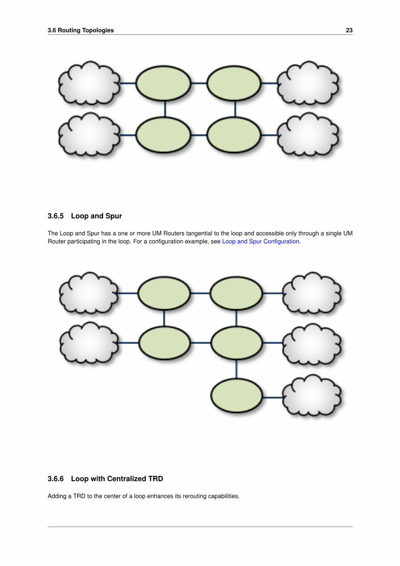
3.6.5 Loop and Spur
The Loop and Spur has a one or more UM Routers tangential to the loop and accessible only through a single UMRouter participating in the loop. For a configuration example, see Loop and Spur Configuration.
3.6.6 Loop with Centralized TRD
Adding a TRD to the center of a loop enhances its rerouting capabilities.

24 UM Router Concepts
3.6.7 with centralized TRD
A Star with a centralized TRD does not offer rerouting capabilities but does provide an economical way to joinmultiple disparate TRDs.
3.6.8 Star with Centralized UM Router
The Star with a centralized UM Router is the simplest way to bridge multiple TRDs. For a configuration example,see Star Configuration.

3.6 Routing Topologies 25
3.6.9 Mesh
The Mesh topology provides peer portal interconnects between many UM Routers, approaching an all-connected-to-all configuration. This provides multiple possible paths between any two TRDs in the mesh. Note that this diagramis illustrative of the ways the UM Routers may be interconnected, and not necessarily a practical or recommendedapplication. For a configuration example, see Mesh Configuration.
3.6.10 Palm Tree
The Palm Tree has a set of series-connected TRDs fanning out to a more richly meshed set of TRDs. This topologytends to pass more concentrated traffic over common links for part of its transit while supporting a loop, star, ormesh near its terminus.

26 UM Router Concepts
3.6.11 Dumbbell
Similar to the Palm Tree, the Dumbbell has a funneled route with a loop, star, or mesh topology on each end.
3.7 Unsupported Configurations
When designing UM Router networks, do not use any of the following topology constructs.
Two peer-to-peer connections between the same two UM Routers:

3.8 UM Feature Compatibility 27
Two endpoint connections from the same UM Router to the same TRD:
Assigning two different Domain ID values (from different UM Routers) to the same TRD:
3.8 UM Feature Compatibility
You must install the UM Dynamic Routing Option with its companion Ultra Messaging UMS, UMP, or UMQ product,and versions must match. While most UM features are compatible with the UM Router, some are not. Following isa table of features and their compatibilities with the UM Router.
UM Feature UM Router Compatible? NotesTransport Acceleration Yes
Hot Failover (HF) Yes The UM Router can pass mes-sages sent by HF publishers to HFreceivers, however the UM Routeritself cannot be configured to origi-nate or terminate HF data streams.
Hot Failover across contexts (HFX) Yes
Late Join YesMessage Batching Yes
Monitoring/Statistics Yes
Multicast Immediate Messaging(MIM)
Yes
Multi-Transport Threads No
Off-Transport Recovery (OTR) Yes
Ordered Delivery Yes
Pre-Defined Messaging (PDM) Yes
Request/Response Yes

28 UM Router Concepts
UM Feature UM Router Compatible? NotesSelf-Describing Messaging (SDM) Yes
Source Side Filtering Yes The UM Router supports transportsource side filtering. You can ac-tivate this either at the originatingTRD source, or at a downstreamproxy source.
Transport LBT-IPC Yes
Transport LBT-RDMA Yes
Transport LBT-RM Yes
Transport LBT-RU Yes
Transport LBT-SMX Partial The UM router does not supportproxy sources sending data via L←↩BT-SMX. Any proxy sources config-ured for LBT-SMX will be convertedto TCP, with a log message warn-ing of the transport change. TheUM Router does accept LBT-SMXingress traffic to proxy receivers.
Transport TCP Yes
Transport TCP-LB Yes
JMS, via UMQ broker NoUM Spectrum Yes The UM Router supports UM Spec-
trum traffic, but you cannot imple-ment Spectrum channels in UMRouter proxy sources or receivers.
UMP Implicit/Explicit Acknowledge-ments
Yes
UMP Persistent Store YesUMP Proxy Sources Yes
UMP Quorum Consensus YesUMP Registration ID/Session Man-agement
Yes
UMP Receiver-Paced Persistence(RPP)
Yes
UMP Store Failover YesUMQ Brokered Queuing No
UMQ Ultra Load Balancing (ULB) No
Ultra Messaging Desktop Services(UMDS)
Not for client connectivity to the U←↩MDS server
Ultra Messaging Manager (UMM) Yes Not for UM Router management
UM SNMP Agent No
UMCache NoWildcard Receivers YesZero Object Delivery (ZOD) Yes

Chapter 4
UM Router Implementation
4.1 UM Router Configuration Overview
When the UM Router daemon launches, it uses configuration option settings to determine its behavior and expecta-tions. You specify option values in an XML configuration file, and reference the file from a command line argument.
Typically, you have a separate XML configuration file for each UM Router, which contains structured configurationelements that describe aspects of the UM Router. Within this XML configuration file, each endpoint portal definitionpoints to a UM configuration file, which allow the portal to properly connect to its TRD.
4.2 Creating Applications for UM Router Compatibility
When developing messaging applications that use Ultra Messaging and, in particular, the UM Router, please ob-serve the following guidelines.
4.2.1 Naming and Identification
An important part to successfully implementing UM Routers is prudent and error-free naming of TRDs, UM Routers,portals, etc., as well as correct identification of IP addresses and ports. It is good practice to first design the UMRouter network by defining all connections and uniquely naming all UM Routers, portals, and TRDs. This works wellas a diagram similar to some examples presented in this document. Include the following names and parameters inyour design diagram:
• TRD names and IDs
• UM Router names
• Portal names
• Portal costs
For example, a well-prepared UM Router design could look like the following figure.

30 UM Router Implementation
4.2.2 Portal Costs
A network of UM Routers uses forwarding cost as the criterion for determining the best (lowest cost) path over whichto resolve a topic and route data. Forwarding cost is simply the sum of all portal costs along a multi-UM Router path.Thus, total cost for the single path in the above example is 34. (Note that this is a non-real-world example, sincecosts are pointless without alternate routes to compare to.) You assign portal costs via the <cost> configurationoption.
After the UM Router network calculates its paths, if a new lower-cost source becomes available, receivers switch tothat path.
4.2.3 Access Control Lists (ACL)
You can apply Access Control Lists (ACL) to a UM Router's portals to filter traffic by certain topics, transports, topicpatterns, multicast groups, etc. You configure ACLs in a UM Router's XML configuration file, as children of an<endpoint> or <peer> portal. As traffic arrives at the portal, the portal either forwards it or rejects it per ACLcriteria.
Inbound ACLs determine what information to forward to other portals in the UM Router, while Outbound ACLsdetermine (by topic) what information from other portals that this portal can send out the UM Router. Each portal(endpoint or peer) can have up to one inbound ACL and one outbound ACL.

4.2 Creating Applications for UM Router Compatibility 31
An ACL can contain one or more Access Control Entries (ACEs). ACEs are the filters that let you match (and acceptor reject based on), criteria elements. For example, to accept only messages for topic ABC:
<acl><inbound>
<ace match="accept"><topic>ABC</topic>
</ace></inbound>
</acl>
Possible ACE condition elements are:
• <multicast-group/> ∗
• <pcre-pattern> (PCRE wildcard patterns)
• <regex-pattern> (Regex wildcard patterns)
• <source-ip/> ∗
• <tcp-source-port/> ∗
• <topic>
• <transport/> ∗
• <udp-destination-port/> ∗
• <udp-source-port/> ∗
• <xport-id/> ∗ (for LBT-IPC traffic)

32 UM Router Implementation
These items apply to only inbound ACLs, and are ignored if used with an outbound ACL.
The above elements are all children of the <ace> element. When an ACL has multiple ACE entries, the UMRouter goes down the list until it finds a match. It then accepts (forwards) or rejects, and is done with that ACL. Animplicit "reject all" is at the end of every ACL, so the UM Router rejects any topic not matched. If you place multipleconditions within an ACE, the UM Router performs an "and" operation with them.
Note that the portal ignores a condition element if a) it is inbound-only and used in an outbound ACL, or b) it simplydoes not apply (such as a <udp-source-port/> if the transport is TCP).
Also note that ACLs can affect topic resolution traffic as well as user messages. They can, for example, block atopic (which prevents the creation of proxy receivers) and, thus, protect remote TRDs from unwanted queries andadvertisements. This effect does not apply to wildcard receivers, however, because ACLs match only on discretetopics. Thus, while ACLs can operate on specific topic traffic derived from wildcard topic resolution, they cannotprevent pattern interest from propagating throughout the network.
Consider the following example, where we configure a portal to forward on specific topics. This example alsoillustrates the parent/child hierarchy for ACLs, ACEs, and ACE conditions.
<endpoint><name>LAN1</name><lbm-config>lan1.cfg</lbm-config><domain-id>1</domain-id>
<acl><inbound><ace match="accept"><topic>ABC</topic>
</ace><ace match="accept"><topic>DEF</topic><transport value=lbt-rm comparison=eq/>
</ace><ace match="accept"><topic>GHI</topic>
</ace></inbound>
</acl></endpoint>
The above example shows each topic match in a separate ACE. When topic "GHI" arrives, the portal finds a matchin the third ACE and forwards the topic. (Placing all three <topic>s in a single ACE would never match anything.)Also note that "DEF" is forwarded only if it uses an LBT-RM transport.
Since the behavior for multiple ACEs is "first match, then done", list ACEs in a specific-to-general order. For theexample below, to forward topic "ABC123" but reject similar topics such as "ABCD123" or "ABCE123", list the ACEfor "ABC123" first (as done below). If the ACE to reject "ABC.∗123" was listed first, it would also (undesirably) matchand reject "ABC123".
<endpoint><name>LAN1</name><lbm-config>lan1.cfg</lbm-config><domain-id>1</domain-id>
<acl><inbound><ace match="accept"><topic>ABC123</topic>
</ace><ace match="reject"><pcre-pattern>ABC.*123</pcre-pattern>
</ace></inbound>
</acl></endpoint>
You can also filter on certain transport types to accept multicast traffic but reject tcp traffic, as shown below.

4.2 Creating Applications for UM Router Compatibility 33
<endpoint><name>LAN1</name><lbm-config>lan1.cfg</lbm-config><domain-id>1</domain-id>
<acl><inbound><ace match="accept"><transport comparison="equal" value="lbtrm"/>
</ace><ace match="reject"><transport comparison="equal" value="tcp"/>
</ace></inbound>
</acl></endpoint>
4.2.4 Timers and Intervals
The UM Router offers a wide choice of timer and interval options to fine tune its behavior and performance. Thereare interactions and dependencies between some of these, and if misconfigured, they may cause race or failureconditions.
This manual's description of configuration options (see XML Configuration Reference), includes identification ofsuch relationships. Please heed them.
4.2.5 Multicast Immediate Messaging Considerations
Multicast Immediate Messages (MIMs) may pass through the UM Router. You cannot filter MIMs with AccessControl Lists (ACL)-MIMs are forwarded to all TRDs. Informatica does not recommend using MIM for messagingtraffic across the UM Router. MIM is intended for short-lived topics and applications that cannot tolerate a delaybetween source creation and the sending of the first message. See also Multicast Immediate Messaging.
4.2.6 Persistence Over the UM Router
The UM Router supports UMP persistence by routing all necessary control and retransmission channels along withtransport and topic resolution traffic. A typical implementation places the UMP persistent store in the same TRD asits registered source, as shown in the following figure.
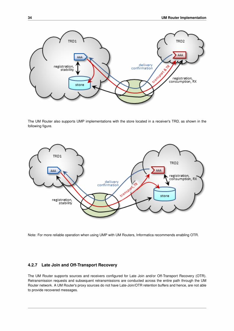
34 UM Router Implementation
The UM Router also supports UMP implementations with the store located in a receiver's TRD, as shown in thefollowing figure.
Note: For more reliable operation when using UMP with UM Routers, Informatica recommends enabling OTR.
4.2.7 Late Join and Off-Transport Recovery
The UM Router supports sources and receivers configured for Late Join and/or Off-Transport Recovery (OTR).Retransmission requests and subsequent retransmissions are conducted across the entire path through the UMRouter network. A UM Router's proxy sources do not have Late-Join/OTR retention buffers and hence, are not ableto provide recovered messages.

4.3 Topology Configuration Examples 35
4.2.8 Topic Resolution Reliability
Topic resolution can sometimes remain in a quiescent phase due to link interruption, preventing needed re-subscription topic resolution activity. Two ways you can address this are:
• For isolated incidents, call lbm_context_topic_resolution_request() (see example lbmtrreq.c). This restartsthe sustaining phase.
• For more chronic problems, such as a UM Router link (especially an endpoint link) over a WAN of ques-tionable reliability, consider configuring Topic resolution to stay in the sustaining phase (options resolver_←↩advertisement_minimum_sustain_duration (source) and resolver_query_minimum_sustain_duration(receiver)).
4.2.9 BOS and EOS Behavior Over the UM Router
Through a network of UM Routers, a topic traverses a separate session for each link along its path. Thus, the UMRouter reports BOS/EOSs based on the activity between the proxy source transport and its associated receiver.There is no end-to-end, application-to-application reporting of the data path state. Also, in the case of multiple topicsbeing assigned to multiple sessions, topics may find themselves with different session mates from hop to hop. Ofcourse, this all influences when, and for which transport session, a topic's BOSs and EOSs are issued.
4.3 Topology Configuration Examples
Following are example configurations for a variety of UM Router topologies. These are the topology examplespresented Routing Topologies.
In a real-world situation, you would have UM Router XML configuration files with their portal interfaces referencingcomplete UM configuration files. However, for these examples, the referred domain configuration files are simplifiedto contain only information relevant to the applicable UM Router. As part of this simplification, domain configurationfiles show interfaces for only one or two transport types.
Also, IP addresses are provided in some cases and omitted in other cases. This is because initiator peer portalsneed to know the IP addresses (and port numbers) of their corresponding acceptor portals to establish connections,whereas endpoint portals communicate via topic resolution and thus, do not need to know IP addresses.
Note
Before designing any UM Router implementations based on configurations or examples other than the typespresented in this document, please contact your technical support representative.
4.3.1 Direct Link Configuration
This example uses a UM Router to connect two topic resolution domain LANs.

36 UM Router Implementation
TRD1 Configuration
This UM configuration file, trd1.cfg, describes TRD1 and is referenced in the UM Router configuration file.
## Global Configuration Options ##context request_tcp_interface 10.29.3.0/24context resolver_multicast_port 13965context resolver_multicast_interface 10.29.3.0/24context resolver_multicast_address 225.1.37.85
G1 Configuration
This UM Router configuration file defines two endpoint portals. In the daemon section, we have turned on monitoringfor the all endpoint portals in the UM Router. The configuration specifies that all statistics be collected every 5seconds and uses the lbm transport module to send statistics to your monitoring application, which runs in TRD1.See also UM Concepts, Monitoring UMS. The Web Monitor has also been turned on (port 15304) to monitor theperformance of the UM Router.
<?xml version="1.0" encoding="UTF-8" ?><!-- G1 xml file- 2 endpoint portals --><tnw-gateway version="1.0">
<daemon><log type="console"/><lbm-license-file>lic0014.txt</lbm-license-file><monitor interval="5"><transport-module module="lbm" options="config=trd1.cfg"/>
</monitor><web-monitor>*:15304</web-monitor>
</daemon><portals>
<endpoint><name>G1-TRD1</name><domain-id>1</domain-id><lbm-config>trd1.cfg</lbm-config>
</endpoint><endpoint><name>G1-TRD2</name><domain-id>2</domain-id><lbm-config>trd2.cfg</lbm-config>
</endpoint></portals>
</tnw-gateway>
TRD2 Configuration
The configuration file trd2.cfg could look something like this.
# Global Configuration Options ##

4.3 Topology Configuration Examples 37
context request_tcp_interface 10.29.3.0/24context resolver_multicast_port 13965context resolver_multicast_interface 10.29.3.0/24context resolver_multicast_address 225.2.37.85
4.3.2 Peer Link Configuration
In cases where the UM Router connection between two TRDs must tunnel through a WAN or TCP/IP network, youcan implement a UM Router at each end, as shown in the example below.
TRD1 Configuration
## Global Configuration Options ##context request_tcp_interface 10.29.3.0/24context resolver_multicast_port 13965context resolver_multicast_interface 10.29.3.0/24context resolver_multicast_address 225.1.37.85
G1 Configuration
Following is an example of two companion peer portals (on different UM Routers) configured via UM Router XMLconfiguration file for a single TCP setup. Note that one must be an initiator and the other, an acceptor.
<?xml version="1.0" encoding="UTF-8" ?><tnw-gateway version="1.0">
<daemon><log type="console"/>
</daemon><portals>
<endpoint><name>G1-TRD1</name><domain-id>1</domain-id><lbm-config>TRD1.cfg</lbm-config>
</endpoint><peer>
<name>G1-G2</name><single-tcp>
<interface>10.30.3.100</interface><initiator>
<address>10.30.3.102</address><port>26123</port>
</initiator></single-tcp>
</peer>

38 UM Router Implementation
</portals></tnw-gateway>
G2 Configuration
<?xml version="1.0" encoding="UTF-8" ?><tnw-gateway version="1.0">
<daemon><log type="console"/>
</daemon><portals><peer>
<name>G2-G1</name><single-tcp><interface>10.30.3.102</interface><acceptor><listen-port>26123</listen-port>
</acceptor></single-tcp>
</peer><endpoint>
<name>G2-TRD2</name><domain-id>2</domain-id><lbm-config>TRD2.cfg</lbm-config>
</endpoint></portals>
</tnw-gateway>
TRD2 Configuration
## LAN2 Configuration Options ##context request_tcp_interface 10.33.3.0/24context resolver_multicast_port 13965
4.3.3 Transit TRD Link Configuration
This example, like the previous one, configures two localized UM Routers tunneling a connection between two TR←↩Ds, however, the UM Routers in this example are tunneling through an intermediate TRD. This has the added effectof connecting three TRDs.
TRD1 Configuration
## TRD1 Configuration Options ##context request_tcp_interface 10.29.3.0/24context resolver_multicast_port 13965

4.3 Topology Configuration Examples 39
context resolver_multicast_interface 10.29.3.0/24context resolver_multicast_address 225.2.37.85
G1 Configuration
Following is an example of two companion peer portals (on different UM Routers) configured via UM Router XMLconfiguration file for a single TCP setup. Note that one must be an initiator and the other, an acceptor.
<?xml version="1.0" encoding="UTF-8" ?><tnw-gateway version="1.0">
<daemon><log type="console"/>
</daemon><portals><endpoint>
<name>G1-TRD1</name><domain-id>1</domain-id><lbm-config>TRD1.cfg</lbm-config>
</endpoint><endpoint>
<name>G1-TRD2</name><domain-id>2</domain-id><lbm-config>TRD2.cfg</lbm-config>
</endpoint></portals>
</tnw-gateway>
TRD2 Configuration
## TRD2 Configuration Options ##context request_tcp_interface 10.29.3.0/24context resolver_multicast_port 13965context resolver_multicast_interface 10.29.3.0/24context resolver_multicast_address 225.2.37.85
G2 Configuration
<?xml version="1.0" encoding="UTF-8" ?><tnw-gateway version="1.0">
<daemon><log type="console"/>
</daemon><portals><endpoint>
<name>G2-TRD2</name><domain-id>2</domain-id><lbm-config>TRD2.cfg</lbm-config>
</endpoint><endpoint>
<name>G2-TRD3</name><domain-id>3</domain-id><lbm-config>TRD3.cfg</lbm-config>
</endpoint></portals>
</tnw-gateway>
TRD3 Configuration
## TRD3 Configuration Options ##context request_tcp_interface 10.29.3.0/24context resolver_multicast_port 13965context resolver_multicast_interface 10.29.3.0/24context resolver_multicast_address 225.3.37.85

40 UM Router Implementation
4.3.4 Parallel Links Configuration
This example is similar in purpose to the single link, peer-to-peer example, except that a second pair of UM Routersis added as a backup route. You can set one of these as a secondary route by assigning a higher cost to portalsalong the path. In this case we set G3 and G4's portal costs to 5, forcing the lower route to be selected only if theupper (G1, G2) route fails.
Also note that we have configured the peer portals for the leftmost or odd-numbered UM Routers as initiators, andthe rightmost or even-numbered UM Router peers as acceptors.
TRD1 Configuration
## TRD1 Configuration Options ##context request_tcp_interface 10.29.3.0/24context resolver_multicast_port 13965context resolver_multicast_interface 10.29.3.0/24context resolver_multicast_address 225.1.37.85
G1 Configuration
<?xml version="1.0" encoding="UTF-8" ?><tnw-gateway version="1.0">
<daemon><log type="console"/>
</daemon><portals><endpoint>
<name>G1-TRD1</name><domain-id>1</domain-id><cost>2</cost><lbm-config>TRD1.cfg</lbm-config>
</endpoint><peer>
<name>G1-G2</name><cost>2</cost><single-tcp>
<interface>10.30.3.101</interface><initiator>
<address>10.30.3.102</address><port>23745</port>
</initiator></single-tcp>
</peer></portals>
</tnw-gateway>

4.3 Topology Configuration Examples 41
G2 Configuration
<?xml version="1.0" encoding="UTF-8" ?><tnw-gateway version="1.0">
<daemon><log type="console"/>
</daemon><portals><peer>
<name>G2-G1</name><cost>2</cost><single-tcp>
<interface>10.30.3.102</interface><acceptor>
<listen-port>23745</listen-port></acceptor>
</single-tcp></peer><endpoint>
<name>G2-TRD2</name><domain-id>2</domain-id><cost>2</cost><lbm-config>TRD2.cfg</lbm-config>
</endpoint></portals>
</tnw-gateway>
G3 Configuration
<?xml version="1.0" encoding="UTF-8" ?><tnw-gateway version="1.0">
<daemon><log type="console"/>
</daemon><portals><endpoint>
<name>G3-TRD1</name><domain-id>1</domain-id><cost>5</cost><lbm-config>TRD1.cfg</lbm-config>
</endpoint><peer>
<name>G3-G4</name><cost>5</cost><single-tcp>
<interface>10.30.3.103</interface><initiator>
<address>10.30.3.104</address><port>23746</port>
</initiator></single-tcp>
</peer></portals>
</tnw-gateway>
G4 Configuration
<?xml version="1.0" encoding="UTF-8" ?><tnw-gateway version="1.0">
<daemon><log type="console"/>
</daemon><portals><peer>
<name>G4-G3</name>

42 UM Router Implementation
<cost>5</cost><single-tcp>
<interface>10.30.3.104</interface><acceptor>
<listen-port>23746</listen-port></acceptor>
</single-tcp></peer><endpoint>
<name>G4-TRD2</name><domain-id>2</domain-id><cost>5</cost><lbm-config>TRD2.cfg</lbm-config>
</endpoint></portals>
</tnw-gateway>
TRD2 Configuration
## TRD2 Configuration Options ##context request_tcp_interface 10.29.3.0/24context resolver_multicast_port 13965context resolver_multicast_interface 10.29.3.0/24context resolver_multicast_address 225.2.37.85
4.3.5 Loop and Spur Configuration
TRD1 Configuration
## Global Configuration Options ##context request_tcp_interface 10.29.3.0/24context resolver_multicast_port 13965context resolver_multicast_interface 10.29.3.0/24context resolver_multicast_address 225.1.37.85
G1 Configuration
4.3 Topology Configuration Examples 43
<?xml version="1.0" encoding="UTF-8" ?><tnw-gateway version="1.0">
<daemon><log type="console"/>
</daemon><portals><peer>
<name>G1_to_G3</name><single-tcp>
<initiator><address>55.55.10.27</address><port>23801</port>
</initiator></single-tcp>
</peer><peer>
<name>G1_to_G2</name><single-tcp>
<initiator><address>55.55.10.26</address><port>23745</port>
</initiator></single-tcp>
</peer><endpoint>
<name>G1_to_TRD1</name><domain-id>1</domain-id><lbm-config>TRD1.cfg</lbm-config>
</endpoint></portals>
</tnw-gateway>
G2 Configuration
<?xml version="1.0" encoding="UTF-8" ?><tnw-gateway version="1.0">
<daemon><log type="console"/>
</daemon><portals><peer>
<name>G2_to_G4</name><single-tcp>
<initiator><address>55.55.10.28</address><port>23632</port>
</initiator></single-tcp>
</peer><peer>
<name>G2_to_G1</name><single-tcp>
<acceptor><listen-port>23745</listen-port>
</acceptor></single-tcp>
</peer><endpoint>
<name>G2_to_TRD2</name><domain-id>2</domain-id><lbm-config>TRD2.cfg</lbm-config>
</endpoint></portals>
</tnw-gateway>
44 UM Router Implementation
TRD2 Configuration
## Global Configuration Options ##context request_tcp_interface 10.29.3.0/24context resolver_multicast_port 13965context resolver_multicast_interface 10.29.3.0/24context resolver_multicast_address 225.2.37.85
TRD3 Configuration
## Global Configuration Options ##context request_tcp_interface 10.29.3.0/24context resolver_multicast_port 13965context resolver_multicast_interface 10.29.3.0/24context resolver_multicast_address 225.3.37.85
G3 Configuration
<?xml version="1.0" encoding="UTF-8" ?><tnw-gateway version="1.0">
<daemon><log type="console"/>
</daemon><portals><peer>
<name>G3_to_G4</name><single-tcp>
<initiator><address>55.55.10.28</address><port>23754</port>
</initiator></single-tcp>
</peer><peer>
<name>G3_to_G1</name><single-tcp>
<acceptor><listen-port>23801</listen-port>
</acceptor></single-tcp>
</peer><endpoint>
<name>G3_to_TRD3</name><domain-id>3</domain-id><lbm-config>TRD3.cfg</lbm-config>
</endpoint></portals>
</tnw-gateway>
G4 Configuration
<?xml version="1.0" encoding="UTF-8" ?><tnw-gateway version="1.0">
<daemon><log type="console"/>
</daemon><portals><peer>
<name>G4_to_G3</name><single-tcp>
<acceptor><listen-port>23754</listen-port>
</acceptor></single-tcp>
</peer>

4.3 Topology Configuration Examples 45
<endpoint><name>G4_to_TRD4</name><domain-id>4</domain-id><lbm-config>TRD4.cfg</lbm-config>
</endpoint><peer>
<name>G4_to_G2</name><single-tcp>
<acceptor><listen-port>23632</listen-port>
</acceptor></single-tcp>
</peer><peer>
<name>G4_to_G5</name><single-tcp>
<initiator><address>55.55.10.29</address><port>23739</port>
</initiator></single-tcp>
</peer></portals>
</tnw-gateway>
TRD4 Configuration
## Global Configuration Options ##context request_tcp_interface 10.29.3.0/24context resolver_multicast_port 13965context resolver_multicast_interface 10.29.3.0/24context resolver_multicast_address 225.4.37.85
G5 Configuration
<?xml version="1.0" encoding="UTF-8" ?><tnw-gateway version="1.0">
<daemon><log type="console"/>
</daemon><portals><endpoint>
<name>G5_to_TRD5</name><domain-id>5</domain-id><lbm-config>TRD5.cfg</lbm-config>
</endpoint><peer>
<name>G5_to_G4</name><single-tcp>
<acceptor><listen-port>23739</listen-port>
</acceptor></single-tcp>
</peer></portals>
</tnw-gateway>
TRD5 Configuration
## Global Configuration Options ##context request_tcp_interface 10.29.3.0/24context resolver_multicast_port 13965context resolver_multicast_interface 10.29.3.0/24context resolver_multicast_address 225.5.37.85

46 UM Router Implementation
4.3.6 Star Configuration
This network consists of four TRDs. Within each TRD, full multicast connectivity exists. However, no multicastconnectivity exists between the four TRDs.
G1 Configuration
The configuration for this UM Router also has transport statistics monitoring and the WebMonitor turned on.
<?xml version="1.0" encoding="UTF-8" ?><!-- UM GW xml file- 3 endpoint portals --><tnw-gateway version="1.0">
<daemon><log type="console"/><lbm-license-file>lic0014.txt</lbm-license-file><monitor interval="5"><transport-module module="lbm" options="config=trd1.cfg"/>
</monitor><web-monitor>*:15304</web-monitor>
</daemon><portals>
<endpoint><name>G1_to_TRD1</name><domain-id>1</domain-id><lbm-config>trd1.cfg</lbm-config>
</endpoint><endpoint><name>G1_to_TRD2</name><domain-id>2</domain-id><lbm-config>trd2.cfg</lbm-config>
</endpoint>

4.3 Topology Configuration Examples 47
<endpoint><name>G1_to_TRD3</name><domain-id>3</domain-id><lbm-config>trd3.cfg</lbm-config>
</endpoint><endpoint><name>G1_to_TRD4</name><domain-id>4</domain-id><lbm-config>trd4.cfg</lbm-config>
</endpoint></portals>
</tnw-gateway>
TRD1 Configuration
## Global Configuration Options ##context request_tcp_interface 10.29.3.0/24context resolver_multicast_port 13965context resolver_multicast_interface 10.29.3.0/24context resolver_multicast_address 225.1.37.85
TRD2 Configuration
## Global Configuration Options ##context request_tcp_interface 10.29.3.0/24context resolver_multicast_port 13965context resolver_multicast_interface 10.29.3.0/24context resolver_multicast_address 225.2.37.85
TRD3 Configuration
## Global Configuration Options ##context request_tcp_interface 10.29.3.0/24context resolver_multicast_port 13965context resolver_multicast_interface 10.29.3.0/24context resolver_multicast_address 225.3.37.85
TRD4 Configuration
## Global Configuration Options ##context request_tcp_interface 10.29.3.0/24context resolver_multicast_port 13965context resolver_multicast_interface 10.29.3.0/24context resolver_multicast_address 225.4.37.85
4.3.7 Mesh Configuration
The mesh topology utilizes many connections between many nodes, to provide a variety of alternate routes. How-ever, meshes are not the best solution in many cases, as unneeded complexity can increase the chance for config-uration errors or make it more difficult to trace problems.

48 UM Router Implementation
TRD1 Configuration
### Global Configuration Options ##context request_tcp_interface 10.29.3.0/24context resolver_multicast_port 13965context resolver_multicast_interface 10.29.3.0/24context resolver_multicast_address 225.1.37.85
G1 Configuration
<?xml version="1.0" encoding="UTF-8" ?><tnw-gateway version="1.0">
<daemon><log type="console"/>
</daemon><portals><peer>
<name>G1_to_G5</name><single-tcp>
<initiator><address>55.55.10.105</address><port>23880</port>
</initiator></single-tcp>
</peer><peer>
<name>G1_to_G4</name><single-tcp>
<initiator><address>55.55.10.104</address><port>23801</port>
</initiator></single-tcp>
</peer><endpoint>
<name>G1_to_TRD1</name><domain-id>1</domain-id><lbm-config>TRD1.cfg</lbm-config>
</endpoint><endpoint>

4.3 Topology Configuration Examples 49
<name>G1_to_TRD2</name><domain-id>2</domain-id><lbm-config>TRD2.cfg</lbm-config>
</endpoint><peer>
<name>G1_to_G2</name><single-tcp>
<initiator><address>55.55.10.102</address><port>23745</port>
</initiator></single-tcp>
</peer></portals>
</tnw-gateway>
G2 Configuration
<?xml version="1.0" encoding="UTF-8" ?><tnw-gateway version="1.0">
<daemon><log type="console"/>
</daemon><portals><peer>
<name>G2_to_G5</name><single-tcp>
<initiator><address>55.55.10.105</address><port>23608</port>
</initiator></single-tcp>
</peer><peer>
<name>G2_to_G4</name><single-tcp>
<acceptor><listen-port>23831</listen-port>
</acceptor></single-tcp>
</peer><peer>
<name>G2_to_G1</name><single-tcp>
<acceptor><listen-port>23745</listen-port>
</acceptor></single-tcp>
</peer><peer>
<name>G2_to_G3</name><single-tcp>
<initiator><address>55.55.10.103</address><port>23632</port>
</initiator></single-tcp>
</peer><endpoint>
<name>G2_to_TRD2</name><domain-id>2</domain-id><lbm-config>TRD2.cfg</lbm-config>
</endpoint></portals>

50 UM Router Implementation
</tnw-gateway>
G3 Configuration
<?xml version="1.0" encoding="UTF-8" ?><tnw-gateway version="1.0">
<daemon><log type="console"/>
</daemon><portals><peer>
<name>G3_to_G5</name><single-tcp>
<initiator><address>55.55.10.105</address><port>23739</port>
</initiator></single-tcp>
</peer><peer>
<name>G3_to_G4</name><single-tcp>
<acceptor><listen-port>23754</listen-port>
</acceptor></single-tcp>
</peer><peer>
<name>G3_to_G2</name><single-tcp>
<acceptor><listen-port>23632</listen-port>
</acceptor></single-tcp>
</peer></portals>
</tnw-gateway>
TRD2 Configuration
## Global Configuration Options ##context request_tcp_interface 10.29.3.0/24context resolver_multicast_port 13965context resolver_multicast_interface 10.29.3.0/24context resolver_multicast_address 225.2.37.85
TRD3 Configuration
## Global Configuration Options ##context request_tcp_interface 10.29.3.0/24context resolver_multicast_port 13965context resolver_multicast_interface 10.29.3.0/24context resolver_multicast_address 225.3.37.85
G4 Configuration
<?xml version="1.0" encoding="UTF-8" ?><tnw-gateway version="1.0">
<daemon><log type="console"/>
</daemon><portals><peer>
<name>G4_to_G5</name><single-tcp>

4.3 Topology Configuration Examples 51
<initiator><address>55.55.10.105</address><port>23580</port>
</initiator></single-tcp>
</peer><endpoint>
<name>G4_to_TRD1</name><domain-id>1</domain-id><lbm-config>TRD1.cfg</lbm-config>
</endpoint><endpoint>
<name>G4_to_TRD3</name><domain-id>3</domain-id><lbm-config>TRD3.cfg</lbm-config>
</endpoint><peer>
<name>G4_to_G1</name><single-tcp>
<acceptor><listen-port>23801</listen-port>
</acceptor></single-tcp>
</peer><peer>
<name>G4_to_G3</name><single-tcp>
<initiator><address>55.55.10.103</address><port>23754</port>
</initiator></single-tcp>
</peer><peer>
<name>G4_to_G2</name><single-tcp>
<initiator><address>55.55.10.102</address><port>23831</port>
</initiator></single-tcp>
</peer></portals>
</tnw-gateway>
G5 Configuration
<?xml version="1.0" encoding="UTF-8" ?><tnw-gateway version="1.0">
<daemon><log type="console"/>
</daemon><portals><peer>
<name>G5_to_G4</name><single-tcp>
<acceptor><listen-port>23580</listen-port>
</acceptor></single-tcp>
</peer><peer>
<name>G5_to_G1</name><single-tcp>

52 UM Router Implementation
<acceptor><listen-port>23880</listen-port>
</acceptor></single-tcp>
</peer><peer>
<name>G5_to_G3</name><single-tcp>
<acceptor><listen-port>23739</listen-port>
</acceptor></single-tcp>
</peer><peer>
<name>G5_to_G2</name><single-tcp>
<acceptor><listen-port>23608</listen-port>
</acceptor></single-tcp>
</peer></portals>
</tnw-gateway>
4.4 Using UM Configuration Files with the UM Router
Within the UM Router configuration file, the endpoint portal's <lbm-config> element lets you import configura-tions from either a plain text or XML UM configuration file. However, using the XML type of UM configuration filesprovides the following advantages over plain text UM configuration files:
• You can apply UM attributes per topic and/or per context.
• You can apply attributes to all portals on a particular UM Router using a UM XML template (instead of indi-vidual portal settings).
• Using UM XML templates to set options for individual portals lets the UM Router process these settings in the<daemon> element instead of within each portal's configuration.
4.4.1 Setting Individual Endpoint Options
When setting endpoint options, first name the context of each endpoint in the UM Router's XML configuration file.
<portals><endpoint>
<name>Endpoint_1</name><domain-id>1</domain-id><source-context-name>G1_E1</source-context-name><lbm-attributes><option name="request_tcp_interface" scope="context" value="10.29.4.0/24"/>
</lbm-attributes></endpoint><endpoint>
<name>G1-TRD2</name>

4.4 Using UM Configuration Files with the UM Router 53
<domain-id>2</domain-id><receiver-context-name>G1_E2</source-context-name><lbm-attributes><option name="request_tcp_interface" scope="context" value="10.29.5.0/24" />
</lbm-attributes></endpoint>
</portals>
Then assign configuration templates to those contexts in the UM XML configuration file.
<application name="tnwgd" template="global"><contexts>
<context name="G1_E1" template="G1-E1-options"><sources />
</context><context name="G1_E2" template="G1-E2-options"><sources />
</context></contexts>
</application>
You specify the unique options for each of this UM Router's two endpoints in the UM XML configuration<templates> section used for G1-E1-options and G1-E2-options.
4.4.2 UM Router and UM XML Configuration Use Cases
One advantage of using UM XML configuration files with the UM Router is the ability to assign unique UM attributesto the topics and contexts used for the proxy sources and receivers (which plain text UM configuration files cannotdo). The following example shows how to assign a different LBTRM multicast address to a source based on itstopic.
Create a new UM XML configuration template for the desired topic name.
<template name="AAA-template"><options type="source">
<option name="transport_lbtrm_multicast_address"default-value="225.2.37.88"/>
</options></template>
Then include this template in the <application> element associated with the UM Router.
<application name="tnwgd" template="global-options"><contexts>
<context><sources template="source-options"><topic topicname="AAA" template="AAA-template" />
</sources></context>
</contexts></application>
It is also possible to assign UM attributes directly in the <application> tag. For example, the following specifiesthat a particular topic should use an LBT-RU transport.
<application name="tnwgd" template="tnwgd-common"><contexts>
<context><sources template="source-template"><topic topicname="LBTRU_TOPIC">
<options type="source">

54 UM Router Implementation
<option name="transport" default-value="lbtru" /></options>
</topic></sources>
</context></contexts>
</application>
4.4.3 Sample Configuration
The following sample configuration incorporates many of the examples mentioned above. The UM Router appliesoptions to all UM objects created. The UM XML configuration file overwrites these options for two specific topics.The first topic, LBTRM_TOPIC, uses a different template to change its transport from TCP to LBTRM, and to setan additional property. The second topic, LBTRU_TOPIC, also changes its transport from TCP to a new value.However, its new attributes are applied directly in its associated topic tag, instead of referencing a template. Inaddition, this sample configuration assigns the rm-source template to all sources and receivers associated with thecontext endpt_1.
4.4.4 XML UM Configuration File
<?xml version="1.0" encoding="UTF-8" ?><um-configuration version="1.0">
<templates><template name="tnwgd-common"><options type="source">
<option name="transport" default-value="tcp" /></options><options type="context">
<option name="request_tcp_interface" default-value="10.29.5.6" /><option name="transport_tcp_port_low" default-value="4400" /><option name="transport_tcp_port_high" default-value="4500" /><option name="resolver_multicast_address" default-value="225.2.37.88"/>
</options></template><template name="rm-source"><options type="source">
<option name="transport" default-value="lbtrm" /><option name="transport_lbtrm_multicast_address"
default-value="225.2.37.89"/></options>
</template></templates><applications>
<application name="tnwgd" template="tnwgd-common"><contexts>
<context><sources>
<topic topicname="LBTRM_TOPIC" template="rm-source" /><topic topicname="LBTRU_TOPIC"><options type="source"><option name="transport" default-value="lbtru" /><option name="resolver_unicast_daemon"
default-value="10.29.5.1:1234" /></options>

4.5 Running the UM Router Daemon 55
</topic></sources>
</context><context name="endpt_1">
<sources template="rm-source"/></context>
</contexts></application>
</applications></um-configuration>
4.4.5 XML UM Router Configuration File
This UM Router uses the above XML UM configuration file, sample-config.xml, to set its UM options. It has threeendpoints, one of which has the context endpt_1.
<?xml version="1.0" encoding="UTF-8" ?><tnw-gateway version="1.0">
<daemon><log type="console"/><xml-config>sample-config.xml</xml-config>
</daemon><portals>
<endpoint><name>Endpoint_1</name><domain-id>1</domain-id><lbm-attributes>
<option name="context_name" scope="context" value="endpt_1" /><option name="request_tcp_interface" scope="context"value="10.29.4.0/24"/>
</lbm-attributes></endpoint><endpoint><name>Endpoint_2</name><domain-id>2</domain-id><lbm-attributes>
<option name="request_tcp_interface" scope="context"value="10.29.5.0/24"/>
</lbm-attributes></endpoint><endpoint><name>Endpoint_3</name><domain-id>3</domain-id><lbm-attributes>
<option name="request_tcp_interface" scope="context"value="10.29.6.0/24"/>
</lbm-attributes></endpoint>
</portals></tnw-gateway>
4.5 Running the UM Router Daemon
To run the UM Router, ensure the following:
• Library environment variable paths are set correctly (LD_LIBRARY_PATH)

56 UM Router Implementation
• The license environment variable LBM_LICENSE_FILENAME points to a valid UM Router license file.
• The configuration file is error free.
Typically, you run the UM Router with one configuration file argument, for example:
tnwgd gw1-config.xml
The UM Router logs version information on startup. The following is an example of this information:
Version 6.0 Build: Sep 26 2012, 00:31:33 (UMS 6.0 [UMP-6.0] [UMQ-6.0] [64-bit]Build: Sep 26 2012, 00:27:17 ( DEBUG license LBT-RM LBT-RU LBT-IPC LBT-RDMA )WC[PCRE 7.4 2007-09-21, regex, appcb] HRT[gettimeofday()])
4.5.1 tnwgd
Name
tnwgd - UM Router Daemon
Synopsis
tnwgd [-d] [--dump-dtd] [-h] [--help] [-f] [--detach] [-v] [--validate] configfile
Description
UM Router services are provided by tnwgd. A UM Router configuration file is required. The contents and format ofthe configuration file are documented separately.
The DTD used to validate a configuration file is dumped to standard output with -d or --dump-dtd. After dumpingthe DTD, tnwgd exits instead of providing UM Router services as usual. See UM Router Configuration DTD for theDTD with comments removed.
To validate the configuration file, use either the -v or --validate options. After attempting validation, tnwgdexits instead of providing UM Router services as usual. The exit status will be 0 for a configuration file successfullyvalidated by the DTD, and non-zero otherwise.
tnwgd normally remains attached to the controlling terminal and runs until interrupted. If the -f or --detachoptions are given, tnwgd instead forks, detaches the child from the controlling terminal, and the parent exits imme-diately.
Command line help is available with -h or --help.
Exit Status
The exit status from tnwgd is 0 for success and some non-zero value for failure.

Chapter 5
XML Configuration Reference
For controlling/configuring each UM Router, you use a XML UM Router configuration file, which also containsreferences to UM configuration files to extract needed information about the TRDs interfaced by endpoint portals.This chapter includes a lookup reference for the XML UM Router configuration file's elements and DTD.
An XML UM Router configuration file follows standard XML conventions. Element declarations or a pointer to a DTDfile are not needed, as these are handled by the UM Router.
5.1 File Structure
An XML UM Router configuration file generally comprises two primary elements: <daemon> and <portals>.Organized and contained within these are option value assignments. <daemon> sub-containers let you set optionsglobal to the UM Router. <portals> sub-containers let you configure each portal in the UM Router individually.
XML UM Router configuration files use the high-level structure shown in the following example. This exampleincludes only some container elements, and only some options.
<?xml version="1.0" encoding="UTF-8" ?><tnw-gateway version="1.0">
<daemon><log type="console"/><uid>0</uid><gid>0</gid><pidfile>/path/file.pid</pidfile><lbm-license-file>/path/file.lic</lbm-license-file><topicmap/><patternmap/><monitor><transport-module/><format-module/>
</monitor><web-monitor>*:21000</web-monitor><propagation-delay/><xml-config>sample-config.xml</xml-config>
</daemon><portals>
<endpoint><name>Endpoint_1</name><domain-id>1</domain-id><cost>1</cost><lbm-config>endpoint2.cfg</lbm-config><lbm-attributes>
<option name="context_name" scope="context" value="endpt_1" />

58 XML Configuration Reference
</lbm-attributes><acl>
<inbound><ace match="accept">
<topic>ABC123</topic><pcre-pattern >pattern</pcre-pattern ><regex-pattern >pattern</regex-pattern ><transport/><source-ip/><multicast-group/><udp-source-port/><udp-destination-port/><tcp-source-port/><xport-id/>
</ace></inbound><outbound>
<ace match="accept"><topic>ABC123</topic><pcre-pattern >pattern</pcre-pattern ><regex-pattern >pattern</regex-pattern ><transport/><source-ip/><multicast-group/><udp-source-port/><udp-destination-port/><tcp-source-port/><xport-id/>
</ace></outbound>
</acl></endpoint><peer><name>Peer_1</name><cost>1</cost><single-tcp>
<interface><receive-buffer><send-buffer><keepalive><nodelay><initiator>
<address><port>
</initiator><acceptor>
<listen-port></acceptor>
</single-tcp><max-queue><max-datagram><batching>
<min-length><batch-interval>
</batching><lbm-config>peer1.cfg</lbm-config><lbm-attributes>
<option name="name" scope="scope" value="value" /></lbm-attributes><acl> (see above)<topic-purge><topic-interest-generate><topic-domain-activity>

5.2 Elements Reference 59
<pattern-purge><pattern-interest-generate><pattern-domain-activity><topic-use-check/><pattern-use-check><source-context-name><receiver-context-name><sqn-window><context-query><gateway-keepalive>
</peer></portals>
</tnw-gateway>
5.2 Elements Reference
Following are descriptions of the XML UM Router configuration file elements. For the children listings, + designates1 or more, designates 0 or more, and ? designates 0 or 1. You must insert children in the order presented.
5.2.1 <tnw-gateway>
The <tnw-gateway> element is a required container for all options residing in the XML UM Router configurationfile. This is the top-level element.
• Cardinality: 1
• Parents: None.
• Children: <daemon>?, <portals>
XML Attributes:
XML Attribute Description Default Value
version The version of the DTD, which is currently 1.0. (This is not the product version.) none
Example:
<tnw-gateway version="1.0"><daemon>
. . .
. . .</daemon><portals>
<endpoint>. . .. . .
</endpoint></portals>
</tnw-gateway>
60 XML Configuration Reference
5.2.2 <daemon>
The <daemon> element is a container for options common to the entire UM Router.
• Cardinality: 0 or 1
• Parents: <tnw-gateway>
• Children: <name>?, <log>?, <uid>?, <gid>?, <pidfile>?, <lbm-license-file>?,<topicmap>?, <patternmap>?, <monitor>?, <web-monitor>?, <daemon-monitor>?<propagation-delay>?, <xml-config>?, <route-info>? <route-recalculation>?
XML Attributes: None.
Example:
<tnw-gateway version="1.0"><daemon>
. . .
. . .</daemon>
. . .
. . .</tnw-gateway>
5.2.3 <name>
The <name> element lets you set a name for this UM Router (do not duplicate for any other known UM Routers),or for the name of an endpoint or peer portal. Each portal name must be unique within the UM Router.
• Cardinality: 1
• Parents: <daemon>, <endpoint>, <peer>
• Children: None.
XML Attributes: None.
Example:
<tnw-gateway version="1.0"><daemon>
<name>UM Router1</name></daemon><portals>
<endpoint><name>endpoint1</name>. . .. . .
</endpoint></portals> . . .
</tnw-gateway>

5.2 Elements Reference 61
5.2.4 <log>
The <log> element specifies the destination for UM Router log messages. If you set the type for file, use thiselement to contain the full pathname/filename.
• Cardinality: 0 or 1
• Parents: <daemon>
• Children: None.
XML Attributes:
XML Attribute Description Default Value
type file, syslog, console console
size Number of millions of bytes of file size to roll log file. E.g. a value of 1 rollsafter 1000000 bytes. Maximum value is 4000. Value of 0 disables rolling byfile size. Only applicable for type="file".
0
frequency Frequency by which to roll log file. Choices aredaily - Roll log file at midnight.hourly - Roll log file after approximately an hour, but is not exact and candrift significantly over a period of time.test - For internal Informatica testing and should not be used.disable - Do not roll log file by frequency.Only applicable for type="file"
disable
xml:space How whitespace is handled. default trims leading and trailing whitespace(e.g., tabs, spaces, linefeeds, etc.), and compresses multiple whitespacecharacters into a single space character. preserve preserves the whitespaceexactly as read.
default
Example:
<tnw-gateway version="1.0"><daemon>
<log type="syslog"/></daemon>
. . .
. . .</tnw-gateway>
5.2.5 <uid>
The <uid> element specifies a User ID (UID) for the daemon process (if run as root).
• Cardinality: 0 or 1
• Parents: <daemon>
• Children: None.
XML Attributes: None.
Example:

62 XML Configuration Reference
<tnw-gateway version="1.0"><daemon>
<uid>5555</uid></daemon>
. . .
. . .</tnw-gateway>
5.2.6 <gid>
The <gid> element specifies a Group ID (GID) for daemon process (if run as root).
• Cardinality: 0 or 1
• Parents: <daemon>
• Children: None.
XML Attributes: None.
Example:
<tnw-gateway version="1.0"><daemon>
<gid>1234</gid></daemon>
. . .
. . .</tnw-gateway>
5.2.7 <pidfile>
The <pidfile> element contains the pathname for daemon process ID (PID) file.
• Cardinality: 0 or 1
• Parents: <daemon>
• Children: None.
XML Attributes:
XML Attribute Description Default Value
xml:space How whitespace is handled. default trims leading and trailing whitespace(e.g., tabs, spaces, linefeeds, etc.), and compresses multiple whitespacecharacters into a single space character. preserve preserves the whitespaceexactly as read.
default
Example:
<tnw-gateway version="1.0"><daemon>
<pidfile>/configs/stores/umestored1/umestored.pid</pidfile> . . .

5.2 Elements Reference 63
</daemon>. . .. . .
</tnw-gateway>
5.2.8 <lbm-license-file>
The <lbm-license-file> element specifies the UM license file's pathname/filename.
• Cardinality: 0 or 1
• Parents: <daemon>
• Children: None.
XML Attributes:
XML Attribute Description Default Value
xml:space How whitespace is handled. default trims leading and trailing whitespace(e.g., tabs, spaces, linefeeds, etc.), and compresses multiple whitespacecharacters into a single space character. preserve preserves the whitespaceexactly as read.
default
Example:
<tnw-gateway version="1.0"><daemon>
. . .<lbm-license-file>lic0014.txt</lbm-license-file>. . .
</daemon>. . .. . .
</tnw-gateway>
5.2.9 <topicmap/>
The <topicmap> element specifies characteristics of the internal topic maps.
• Cardinality: 0 or 1
• Parents: <daemon>
• Children: None.
XML Attributes:

64 XML Configuration Reference
XML Attribute Description Default Value
hash-function Topic map hash function to use. Choices are:classic - A "classic" good string hash function. Works best when topic nameshave a constant prefix with a changing suffix.djb2 - The Dan Bernstein algorithm from comp.lang.c. Works best when topicnames have a changing prefix with a constant suffix.sdbm - sdbm database library (used in Berkeley DB). A useful alternative todjb2.murmur2 - Good all-around hash function by Austin Appleby. Best for mediumto long topic strings.
murmur2
size Number of entries in the topic map. 131111
Example:
<tnw-gateway version="1.0"><daemon>
< topicmap hash-function="djb2" size="5000"></daemon>
. . .
. . .</tnw-gateway>
5.2.10 <patternmap/>
The <patternmap> element determines characteristics of the internal pattern maps.
• Cardinality: 0 or 1
• Parents: <daemon>
• Children: None.
XML Attributes:
XML Attribute Description Default Value
hash-function Pattern map hash function to use. Choices areclassic - A "classic" good string hash function. Works best when topic nameshave a constant prefix with a changing suffix.djb2 - The Dan Bernstein algorithm from comp.lang.c. Works best when topicnames have a changing prefix with a constant suffix.sdbm - sdbm database library (used in Berkeley DB). A useful alternative todjb2.murmur2 - Good all-around hash function by Austin Appleby. Best for mediumto long topic strings.
murmur2
size Number of entries in the pattern map. 131111
Example:
<tnw-gateway version="1.0"><daemon>
<patternmap hash-function="djb2" size="5000"></daemon>
. . .

5.2 Elements Reference 65
. . .</tnw-gateway>
5.2.11 <monitor>
The <monitor> element is a container for monitoring configuration elements.
• Cardinality: 0 or 1
• Parents: <daemon>
• Children: <transport-module>?, <format-module>
XML Attributes:
XML Attribute Description Default Valueinterval Monitoring interval, in seconds. 0 disables monitoring. 0
Example:
<tnw-gateway version="1.0"><daemon>
<monitor interval=30><transport-module module="lbm" options="config=/cfgs/TD1.cfg;topic=stats"/><format-module options="config=/cfgs/TD1.cfg;separator=|"/>
</monitor></daemon>
. . .
. . .</tnw-gateway>
5.2.12 <transport-module/>
The <transport-module> element specifies characteristics about the monitoring transport module used.
• Cardinality: 0 or 1
• Parents: <monitor>
• Children: None.
XML Attributes:
XML Attribute Description Default Value
module Specifies the monitoring transport module to use. Choices are lbm (LBMM←↩ON UMS), lbmsnmp (LBMMON SNMP), or udp (LBMMON UDP).
lbm
options Option string to be passed to the transport module. Available options areconfig (configuration path and filename), topic (the topic name to use forsending and receiving statistics; default /29west/statistics), and wctopic (formonitor receivers only, a wildcard pattern).
none

66 XML Configuration Reference
Example:
<tnw-gateway version="1.0"><daemon>
<monitor interval=30><transport-module module="lbm" options="config=/cfgs/TD1.cfg;topic=stats"/><format-module options="config=/cfgs/TD1.cfg;separator=|"/>
</monitor></daemon>
. . .
. . .</tnw-gateway>
5.2.13 <format-module/>
The <format-module> element provides specifics about the monitoring format module.
• Cardinality: 0 or 1
• Parents: <monitor>
• Children: None.
XML Attributes:
XML Attribute Description Default Value
module Currently, the one available choice is csv (comma-separated variables). csv
options Option string to be passed to the format module. The one available option isseparator (field separator character).
none
Example:
<tnw-gateway version="1.0"><daemon>
<monitor interval=30><transport-module module="lbm" options="config=/cfgs/TD1.cfg;topic=stats"/><format-module options="separator=|"/>
</monitor></daemon>
. . .
. . .</tnw-gateway>
5.2.14 <web-monitor>
The <web-monitor> element identifies the address for the web monitor, in the form of interface:port. You canuse "∗" to specify the local host.
• Cardinality: 0 or 1
• Parents: <daemon>
• Children: None.

5.2 Elements Reference 67
XML Attributes:
XML Attribute Description Default Value
xml:space How whitespace is handled. default trims leading and trailing whitespace(e.g., tabs, spaces, linefeeds, etc.), and compresses multiple whitespacecharacters into a single space character. preserve preserves the whitespaceexactly as read.
default
Example:
<tnw-gateway version="1.0"><daemon>
<web-monitor>*:21001</web-monitor></daemon>
. . .
. . .</tnw-gateway>
5.2.15 <daemon-monitor>
The <daemon-monitor> element configures the Daemon Statistics feature. See Daemon Statistics for gen-eral information on Daemon Statistics.
• Cardinality: 0 or 1
• Parents: <daemon>
• Children: <lbm-config>?, <publishing-interval>?, <remote-snapshot-request>?,<remote-config-changes-request>?
XML Attributes:
XML Attribute Description Default Value
topic Topic name to use for publishing Daemon Statistics. "tnwgd.monitor"
Example:
<tnw-gateway version="1.0"><daemon>
<daemon-monitor topic="umrouter.1"><lbm-config>/path/umrouter_monitor.cfg</lbm-config><publishing-interval>
. . .</publishing-interval><remote-snapshot-request allow="1"/><remote-config-changes-request allow="0"/>
</daemon-monitor></daemon>
. . .
. . .</tnw-gateway>

68 XML Configuration Reference
5.2.16 <remote-snapshot-request>
The <remote-snapshot-request> element configures whether the UM Router will respond to monitoringapps requests to send on-demand snapshots of daemon statistics. See Daemon Statistics for general informationon Daemon Statistics.
• Cardinality: 0 or 1
• Parents: <daemon-monitor>
• Children: none.
XML Attributes:
XML Attribute Description Default Valueallow Enable or disable snapshot requests. 1 means that the UM Router will re-
spond to snapshot requests. 0 means that snapshot requests will be ignored.0
Example:
<tnw-gateway version="1.0"><daemon>
<daemon-monitor topic="umrouter.1"><lbm-config>/path/umrouter_monitor.cfg</lbm-config><publishing-interval>
. . .</publishing-interval><remote-snapshot-request allow="1"/><remote-config-changes-request allow="0"/>
</daemon-monitor></daemon>
. . .
. . .</tnw-gateway>
5.2.17 <remote-config-changes-request>
The <remote-config-changes-request> element configures whether the UM Router will respond tomonitoring apps requests to change the rate at which Daemon Statistics messages are published. See DaemonStatistics for general information on Daemon Statistics.
• Cardinality: 0 or 1
• Parents: <daemon-monitor>
• Children: none.
XML Attributes:
XML Attribute Description Default Valueallow Enable or disable change requests. 1 means that the UM Router will respond
to change requests. 0 means that change requests will be ignored.0
Example:

5.2 Elements Reference 69
<tnw-gateway version="1.0"><daemon>
<daemon-monitor topic="umrouter.1"><lbm-config>/path/umrouter_monitor.cfg</lbm-config><publishing-interval>
. . .</publishing-interval><remote-snapshot-request allow="1"/><remote-config-changes-request allow="0"/>
</daemon-monitor></daemon>
. . .
. . .</tnw-gateway>
5.2.18 <xml-config>
The <xml-config> element specifies the UM XML configuration file.
• Cardinality: 0 or 1
• Parents: <daemon>
• Children: None.
XML Attributes:
XML Attribute Description Default Value
xml:space How whitespace is handled. default trims leading and trailing whitespace(e.g., tabs, spaces, linefeeds, etc.), and compresses multiple whitespacecharacters into a single space character. preserve preserves the whitespaceexactly as read.
default
Example:
<tnw-gateway version="1.0"><daemon>
<xml-config>configfile.xml</xml-config></daemon>
. . .
. . .</tnw-gateway><route-info propagation-interval="1000" check-interval="750" timeout="4000"
max-hop-count="100"/><route-recalculation backoff-interval="5000" warning-interval="10000"/>
5.2.19 <route-info>
The <route-info> element lets you set control parameters for UM Router initial route setup (or reroute) be-havior.
• Cardinality: 0 or 1

70 XML Configuration Reference
• Parents: <daemon>
• Children: None.
XML Attributes:
XML Attribute Description Default Value
propagation-interval The time interval between route information messages that the UMRouter sends to other UM Routers
1000
check-interval How often the UM Router checks to see if a route information messageneeds to be sent, a UM Router has timed out, and/or the routes needto be recalculated.
750
timeout How long a UM Router waits after receiving no route information mes-sages from another UM Router before determining that that UM Routeris out of service or unreachable.
4000
max-hop-count The maximum number of UM Routers a route information message cantraverse before being discarded.
100
xml:space How whitespace is handled. default trims leading and trailing whites-pace (e.g., tabs, spaces, linefeeds, etc.), and compresses multiplewhitespace characters into a single space character. preserve pre-serves the whitespace exactly as read.
default
Example:
<tnw-gateway version="1.0"><daemon>
<route-info propagation-interval="1000" check-interval="750" timeout="4000"max-hop-count="100"/>
</daemon>. . .. . .
</tnw-gateway>
5.2.20 <route-recalculation>
The <route-recalculation> element lets you set timing parameters for UM Router rerouting route calcu-lation behavior.
• Cardinality: 0 or 1
• Parents: <daemon>
• Children: None.
XML Attributes:
XML Attribute Description Default Value
backoff-interval How long, in milliseconds, the UM Router waits after the last detectedchange in topology before initiating a route recalculation
5000
warning-interval How long, in milliseconds, the UM Router waits before warning that a routerecalculation is being held up due to a non-converging topology.
10000
xml:space How whitespace is handled. default trims leading and trailing whitespace(e.g., tabs, spaces, linefeeds, etc.), and compresses multiple whitespacecharacters into a single space character. preserve preserves the whites-pace exactly as read.
default

5.2 Elements Reference 71
Example:
<tnw-gateway version="1.0"><daemon>
<route-recalculation backoff-interval="5000" warning-interval="10000"/></daemon>
. . .
. . .</tnw-gateway>
5.2.21 <portals>
The <portals> element is a container for all endpoint and peer portal configuration information.
• Cardinality: 0 or 1
• Parents: <daemon>
• Children: (<endpoint> | <peer>)+
XML Attributes:None.
Example:
<tnw-gateway version="1.0">. . .. . .
<portals><endpoint>
. . .
. . .</endpoint>
</portals></tnw-gateway>
5.2.22 <endpoint>
The <endpoint> element is a container element for all configuration options of a single endpoint portal.
• Cardinality:0 or more
• Parents: <portals>
• Children: <name>, <domain-id>, <cost>?, <source-deletion-delay>?, <max-queue>?,<smart-batch>?, <lbm-config>?, <lbm-attributes>?, <acl>?, <topic-resolution>?,<late-join>?, <topic-purge>?, <topic-interest-generate>?, <topic-domain-activity>?,<pattern-purge>?, <pattern-interest-generate>?, <pattern-domain-activity>?,<remote-topic>?, <remote-pattern>?, <source-context-name>?, <receiver-context-name>?,<sqn-window>?, <context-query>?, <publishing-interval>?
XML Attributes: None.
Example:

72 XML Configuration Reference
<tnw-gateway version="1.0"><daemon>
. . .
. . .</daemon><portals>
<endpoint><name>E1</name><domain-id>1</domain-id><cost>1</cost>. . .. . .
</endpoint></portals>
</tnw-gateway>
5.2.23 <domain-id>
The <domain-id> element identifies the TRD for this endpoint portal. It must be unique within the UM Router(which means that for any TRD, you can assign only one endpoint portal per UM Router). Also, all endpointsinterfacing a given TRD must have the same <domain-id> value.
• Cardinality:1
• Parents: <endpoint>
• Children: None.
XML Attributes: None.
Example:
<tnw-gateway version="1.0"><daemon>
. . .
. . .</daemon><portals>
<endpoint><name>E1</name><domain-id>1</domain-id><cost>1</cost>. . .. . .
</endpoint></portals>
</tnw-gateway>
5.2.24 <cost>
The <cost> element assigns a positive non-zero integer cost to the portal. The default value is 1.
• Cardinality: 0 or 1
• Parents: <endpoint> <peer>

5.2 Elements Reference 73
• Children: None.
XML Attributes: None.
Example:
<tnw-gateway version="1.0"><daemon>
. . .
. . .</daemon><portals>
<endpoint><name>E1</name><domain-id>1</domain-id><cost>25</cost>. . .. . .
</endpoint></portals>
</tnw-gateway>
5.2.25 <source-deletion-delay>
The <source-deletion-delay> element sets the time in milliseconds to wait after a route map changeoccurs before deleting a proxy source. Such a route map change could be due to failure of a UM Router or linkwithin a network.
• Cardinality: 0 or 1
• Parents: <endpoint>
• Children: None.
XML Attributes: None.
Example:
<tnw-gateway version="1.0"><daemon>
. . .
. . .</daemon><portals>
<endpoint><name>E1</name><domain-id>1</domain-id><source-deletion-delay>500</source-deletion-delay>. . .. . .
</endpoint></portals>
</tnw-gateway>

74 XML Configuration Reference
5.2.26 <max-queue>
The <max-queue> element sets the maximum buffer size for blocking messages. If not specified, this defaultsto 1000000 bytes.
• Cardinality: 0 or 1
• Parents: <endpoint> <peer>
• Children: None.
XML Attributes: None.
Example:
<tnw-gateway version="1.0"><daemon>
. . .
. . .</daemon><portals>
<endpoint><name>E1</name><domain-id>1</domain-id><max-queue>500000</max-queue>. . .. . .
</endpoint></portals>
</tnw-gateway>
5.2.27 <lbm-config>
The <lbm-config> element specifies the UM configuration file that contains configuration options associatedwith this portal.
• Cardinality: 0 or 1
• Parents: <endpoint> <peer>
• Children: None.
XML Attributes:
XML Attribute Description Default Value
xml:space How whitespace is handled. default trims leading and trailing whitespace(e.g., tabs, spaces, linefeeds, etc.), and compresses multiple whitespacecharacters into a single space character. preserve preserves the whitespaceexactly as read.
default
Example:
<tnw-gateway version="1.0">. . .. . .
<portals><endpoint>

5.2 Elements Reference 75
<name>E2</name><domain-id>1</domain-id><lbm-config>/path/endpoint2.cfg</lbm-config>. . .. . .
</endpoint></portals>
</tnw-gateway>
5.2.28 <lbm-attributes>
The <lbm-attributes> element is a container for individual UM-option-setting elements. It lets you set in-dividual UM attributes without referencing a UM configuration file. These values override any values set via filesreferenced by <lbm-config>.
• Cardinality: 0 or 1
• Parents: <endpoint> <peer>
• Children: <option>+
XML Attributes:None.
Example:
<tnw-gateway version="1.0">. . .. . .
<portals><endpoint>
<name>E2</name><domain-id>1</domain-id><lbm-attributes><option scope="context" name="request_tcp_interface" value="10.28.5.5" /><option scope="context" name="response_tcp_interface" value="127.0.0.1" />
</lbm-attributes> . . .. . .
</endpoint></portals>
</tnw-gateway>
5.2.29 <option/>
The <option> element lets you set an individual UM configuration option without referencing a UM configurationfile. This value overrides any values set via files referenced by <lbm-config>.
• Cardinality: 1 or more
• Parents: <lbm-attributes>
• Children: None.
XML Attributes:

76 XML Configuration Reference
XML Attribute Description Default Value
scope The type of object to which an option can apply. Possible scopes are context,source, receiver, wildcard_receiver, event_queue, and hfx.
none
name The name of the option. none
value The value of the option. none
Note
Some UM options specify interfaces, which can be done by supplying the device name of the interface. Specialcare must be taken when supplying device names. See Interface Device Names and XML for details.
Example:
<tnw-gateway version="1.0">. . .. . .
<portals><endpoint><name>E2</name><domain-id>1</domain-id><lbm-attributes>
<option scope="context" name="request_tcp_interface" value="127.0.0.1" /><option scope="context" name="response_tcp_interface" value="10.28.5.5" />
</lbm-attributes> . . .. . .
</endpoint></portals>
</tnw-gateway>
5.2.30 <acl>
The <acl> element contains elements (inbound and outbound ACEs) that describe how an ACL (Access ControlList) filters messages.
• Cardinality: 0 or 1
• Parents: <endpoint> <peer>
• Children: <inbound>?, <outbound>?
XML Attributes: None.
Example:
<tnw-gateway version="1.0">. . .. . .
<portals><endpoint><acl>
<inbound><ace>
<topic>AAA</topic></ace>
</inbound></acl>
</endpoint></portals>
</tnw-gateway>

5.2 Elements Reference 77
5.2.31 <inbound>
The <inbound> element is a container for ACE elements, to separate inbound ACEs from outbound ACEs.
• Cardinality: 0 or 1
• Parents: <acl>
• Children: <ace>+
XML Attributes: None.
Example:
<tnw-gateway version="1.0">. . .. . .
<portals><endpoint>
<acl><inbound>
<ace><topic>AAA</topic>
</ace></inbound>
</acl></endpoint>
</portals></tnw-gateway>
5.2.32 <outbound>
The <outbound> element is a container for ACE elements, to separate outbound ACEs from inbound ACEs.
• Cardinality: 0 or 1
• Parents: <acl>
• Children: <ace>+
XML Attributes: None.
Example:
<tnw-gateway version="1.0">. . .. . .
<portals><endpoint>
<acl><outbound>
<ace><pcre-pattern>A[AB]A</pcre-pattern>
</ace></outbound>

78 XML Configuration Reference
</acl></endpoint>
</portals></tnw-gateway>
5.2.33 <ace>
Within an inbound or outbound ACL, you can have one or more <ace> elements. Each ACE (Access ControlEntry). lets you match and accept or reject messages based on access control condition elements, which are theelements contained within an <ace> element.
• Cardinality: 0 or 1
• Parents: <inbound> <outbound>
• Children: (<topic> |<pcre-pattern> |<regex-pattern> |<transport> |<source-ip>|<multicast-group> |<udp-source-port> |<udp-destination-port> |<tcp-source-port>| <xport-id>)+
XML Attributes:
XML Attribute Description Default Valuematch This required attribute determines what to do with matched messages. Pos-
sible values are accept or reject.none
Example:
<tnw-gateway version="1.0"><portals>
<endpoint><name>LAN1</name><lbm-config>lan1.cfg</lbm-config><domain-id>1</domain-id>
<acl><inbound><ace match="accept"><topic>ABC</topic>
</ace><ace match="accept"><topic>DEF</topic><transport value=lbt-rm comparison=eq/>
</ace><ace match="accept"><topic>GHI</topic>
</ace></inbound>
</acl></endpoint>
. . .
. . .

5.2 Elements Reference 79
5.2.34 <topic>
The <topic> element defines a condition used in an ACE. Specifically, this is a match pattern for a topic name.
• Cardinality: 0 or more
• Parents: <ace> (inbound only)
• Children: None.
XML Attributes:
XML Attribute Description Default Value
xml:space How whitespace is handled. default trims leading and trailing whitespace(e.g., tabs, spaces, linefeeds, etc.), and compresses multiple whitespacecharacters into a single space character. preserve preserves the whitespaceexactly as read.
default
Example:
<ace match="accept"><topic>ABC</topic>
</ace>
5.2.35 <pcre-pattern>
The <pcre-pattern> element defines a condition used in an ACE. Specifically, this is a match pattern for aPCRE regular expression matched in the message.
• Cardinality: 0 or more
• Parents: <ace>
• Children: None.
XML Attributes:
XML Attribute Description Default Value
xml:space How whitespace is handled. default trims leading and trailing whitespace(e.g., tabs, spaces, linefeeds, etc.), and compresses multiple whitespacecharacters into a single space character. preserve preserves the whitespaceexactly as read.
default
Example:
<ace match="accept"><pcre-pattern>ABC</pcre-pattern>
</ace>

80 XML Configuration Reference
5.2.36 <regex-pattern>
The <regex-pattern> element defines a condition used in an ACE. Specifically, this is a match pattern for aRegEx regular expression matched in the message.
This element is deprecated.
• Cardinality: 0 or more
• Parents: <ace>
• Children: None.
XML Attributes:
XML Attribute Description Default Value
xml:space How whitespace is handled. default trims leading and trailing whitespace(e.g., tabs, spaces, linefeeds, etc.), and compresses multiple whitespacecharacters into a single space character. preserve preserves the whitespaceexactly as read.
default
Example:
<ace match="accept"><regex-pattern>ABC</regex-pattern>
</ace>
5.2.37 <transport/>
The <transport> element defines a condition used in an ACE. Specifically, this is a match pattern for a UMtransport type.
• Cardinality: 0 or more
• Parents: <ace> (inbound only)
• Children: None.
XML Attributes:
XML Attribute Description Default Value
comparison Defines a match condition. Choices are equal (eq or equal) or not equal (neor notequal).
none
value The value to be matched via the comparison. Choices are: tcp, lbt-rm, lbt-ru,lbt-ipc. Also acceptable are lbtrm, lbtru, lbtipc.
none
Example:
<ace match="accept"><transport comparison="equal" value="lbtrm"/>
</ace>

5.2 Elements Reference 81
5.2.38 <source-ip/>
The <source-ip> element defines a condition used in an ACE. Specifically, this is a match pattern for themessage source IP address. This applies only to TCP, LBT-RM, and LBT-RU transports.
• Cardinality: 0 or more
• Parents: <ace> (inbound only)
• Children: None.
XML Attributes:
XML Attribute Description Default Value
comparison Defines a match condition. Choices are equal (eq or equal) or not equal(ne or notequal), less than (lt or lessthan), less than or equal (le orlessthanequal), greater than (gt or greaterthan), or greater than or equal (geor greaterthanequal
none
value The source IP address as a dotted-decimal value to be matched via the com-parison.
none
Example:
<ace match="accept"><source-ip comparison="equal" value="127.0.0.1"/>
</ace>
5.2.39 <multicast-group/>
The <multicast-group> element defines a condition used in an ACE. Specifically, this is a match pattern forthe message's multicast group address. This applies only to LBT-RM transports.
• Cardinality: 0 or more
• Parents: <ace> (inbound only)
• Children: None.
XML Attributes:
XML Attribute Description Default Value
comparison Defines a match condition. Choices are equal (eq or equal) or not equal(ne or notequal), less than (lt or lessthan), less than or equal (le orlessthanequal), greater than (gt or greaterthan), or greater than or equal (geor greaterthanequal
none
value The multicast group IP address as a dotted-decimal value to be matched viathe comparison.
none
Example:
<ace match="accept"><multicast-group comparison="equal" value="239.101.1.1"/>
</ace>

82 XML Configuration Reference
5.2.40 <udp-source-port/>
The <udp-source-port> element defines a condition used in an ACE. Specifically, this is a match pattern forthe message's UDP source port number. This applies only to LBT-RM and LBT-RU transports.
• Cardinality: 0 or more
• Parents: <ace> (inbound only)
• Children: None.
XML Attributes:
XML Attribute Description Default Value
comparison Defines a match condition. Choices are equal (eq or equal) or not equal(ne or notequal), less than (lt or lessthan), less than or equal (le orlessthanequal), greater than (gt or greaterthan), or greater than or equal (geor greaterthanequal
none
value The UDP source port number. none
Example:
<ace match="accept"><udp-source-port comparison="equal" value="1234"/>
</ace>
5.2.41 <udp-destination-port/>
The <udp-destination-port> element defines a condition used in an ACE. Specifically, this is a matchpattern for the message's UDP destination port number. This applies only to LBT-RM transports.
• Cardinality: 0 or more
• Parents: <ace> (inbound only)
• Children: None.
XML Attributes:
XML Attribute Description Default Value
comparison Defines a match condition. Choices are equal (eq or equal) or not equal(ne or notequal), less than (lt or lessthan), less than or equal (le orlessthanequal), greater than (gt or greaterthan), or greater than or equal (geor greaterthanequal
none
value The UDP destination port number. none
Example:
<ace match="accept"><udp-destination-port comparison="equal" value="1234"/>
5.2 Elements Reference 83
</ace>
5.2.42 <tcp-source-port/>
The <tcp-source-port> element defines a condition used in an ACE. Specifically, this is a match pattern forthe message's TCP source port number. This applies only to TCP transports.
• Cardinality: 0 or more
• Parents: <ace> (inbound only)
• Children: None.
XML Attributes:
XML Attribute Description Default Value
comparison Defines a match condition. Choices are equal (eq or equal) or not equal(ne or notequal), less than (lt or lessthan), less than or equal (le orlessthanequal), greater than (gt or greaterthan), or greater than or equal (geor greaterthanequal
none
value The TCP source port number. none
Example:
<ace match="accept"><tcp-source-port comparison="equal" value="1234"/>
</ace>
5.2.43 <xport-id/>
The <xport-id> element defines a condition used in an ACE. Specifically, this is a match pattern for the mes-sage's xport ID number. This applies only to LBT-IPC transports.
• Cardinality: 0 or more
• Parents: <ace> (inbound only)
• Children: None.
XML Attributes:
XML Attribute Description Default Value
comparison Defines a match condition. Choices are equal (eq or equal) or not equal(ne or notequal), less than (lt or lessthan), less than or equal (le orlessthanequal), greater than (gt or greaterthan), or greater than or equal (geor greaterthanequal
none
value The xport ID number. none
Example:

84 XML Configuration Reference
<ace match="accept"><xport-id comparison="equal" value="1234"/>
</ace>
5.2.44 <topic-resolution>
The <topic-resolution> element is a container for UM Router topic resolution behavior options.
• Cardinality: 0 or 1
• Parents: <endpoint>
• Children: <topic-use-query>?, <pattern-use-query>?, <remote-topic-interest>?,<remote-pattern-interest>?, <domain-route>?, <initial-request>?
XML Attributes: None.
Example:
<tnw-gateway version="1.0">. . .. . .
<portals><endpoint><topic-resolution>
<initial-request><rate-limit/>
</initial-request></topic-resolution>
</endpoint></portals>
</tnw-gateway>
5.2.45 <initial-request/>
The <initial-request> element sets interval and duration for initial topic resolution requests.
• Cardinality: 0 or 1
• Parents: <topic-resolution>
• Children: None.
XML Attributes:
XML Attribute Description Default Value
duration The minimum duration for which the initial topic resolution requests are sent.Before changing the value of this option, please contact Informatica Sup-port.
10
periodic-interval The interval at which the initial topic resolution requests are sent. Beforechanging the value of this option, please contact Informatica Support
1000
5.2 Elements Reference 85
Example:
<tnw-gateway version="1.0">. . .. . .
<portals><endpoint><topic-resolution>
<initial-request duration="15" periodic-interval="800"/></topic-use-query>
</topic-resolution></endpoint>
</portals></tnw-gateway>
5.2.46 <topic-use-query>
The <topic-use-query> element sets parameters for when and how often this endpoint portal sends topicuse queries.
• Cardinality: 0 or 1
• Parents: <topic-resolution>
• Children: <rate-limit>
XML Attributes:
XML Attribute Description Default Value
max Maximum number of topic use queries to send for a given topic, each sepa-rated by the timeout value before giving up and removing the topic from thetopic list. Before changing the value of this option, please contact Informat-ica Support.
5
periodic-interval The interval, in milliseconds, between periodic topic use queries being sentfor each topic the portal has interest in. Before changing the value of thisoption, please contact Informatica Support.
300000
timeout The maximum time, in milliseconds, to wait for a topic use response. Beforechanging the value of this option, please contact Informatica Support.
3000
Example:
<tnw-gateway version="1.0">. . .. . .
<portals><endpoint><topic-resolution>
<topic-use-query max="6" periodic-interval="250000" timeout="4000"><rate-limit/>
</topic-use-query></topic-resolution>
</endpoint></portals>
</tnw-gateway>

86 XML Configuration Reference
5.2.47 <rate-limit/>
The <rate-limit> element sets rate limits for topic resolution data sent over the network.
You can set rate limits individually for each of the following topic resolution message types:
• topic use query
• pattern use query
• topic interest
• pattern interest
• domain route
• Cardinality: 0 or 1
• Parents: <topic-use-query> <pattern-use-query> <remote-topic-interest><remote-pattern-interest> <domain-route>
• Children: None.
XML Attributes: You can set a limit in bps, objects per second, or both. The UM Router begins limiting when thelower of these attributes is reached.
XML Attribute Description Default Value
bps The limit in Bits per Second that data will besent on the network. A value of 0 disableslimiting by bits per second. Before chang-ing the value of this option, please contactInformatica Support.
For use queries and interest messages←↩: 500000For domain route messages: 0
objects-per-second The limit in Objects per Second that datawill be sent on the network. A value of 0 dis-ables limiting by objects per second. Beforechanging the value of this option, pleasecontact Informatica Support.
For use queries:500For interest messages: 0For domain route messages: 50
Example:
<tnw-gateway version="1.0">. . .. . .
<portals><endpoint><topic-resolution>
<topic-use-query max="6" periodic-interval="250000" timeout="4000"/><rate-limit bps="550000" objects-per-second="0"/>
</topic-use-query></topic-resolution>
</endpoint></portals>
</tnw-gateway>

5.2 Elements Reference 87
5.2.48 <pattern-use-query>
The <pattern-use-query> element sets parameters for when and how often this endpoint portal sendspattern use queries.
• Cardinality: 0 or 1
• Parents: <topic-resolution>
• Children: <rate-limit>
XML Attributes:
XML Attribute Description Default Value
max Maximum number of pattern use queries to send for a given pattern, eachseparated by the timeout value before giving up and removing the topicfrom the topic list. Before changing the value of this option, please contactInformatica Support.
5
periodic-interval The interval, in milliseconds, between periodic pattern use queries beingsent for each pattern the portal has interest in. Before changing the valueof this option, please contact Informatica Support.
300000
timeout The maximum time, in milliseconds, to wait for a pattern use response. Be-fore changing the value of this option, please contact Informatica Support.
3000
Example:
<tnw-gateway version="1.0">. . .. . .
<portals><endpoint><topic-resolution>
<pattern-use-query max="6" periodic-interval="250000" timeout="4000"><rate-limit/>
</topic-use-query></topic-resolution>
</endpoint></portals>
</tnw-gateway>
5.2.49 <remote-topic-interest>
The <remote-topic-interest> element sets parameters for when and how often this endpoint portal sendstopic interest messages.
• Cardinality: 0 or 1
• Parents: <topic-resolution>
• Children: <rate-limit>
XML Attributes:

88 XML Configuration Reference
XML Attribute Description Default Valuemin-interval The minimum interval, in milliseconds, between topic interest messages be-
ing sent for each topic the portal has interest in.1000
max-interval The maximum interval, in milliseconds, between topic interest messages be-ing sent for each topic the portal has interest in.
60000
Example:
<tnw-gateway version="1.0">. . .. . .
<portals><endpoint><topic-resolution>
<remote-topic-interest min-interval="1000" max-interval="90000"><rate-limit/>
</remote-topic-interest></topic-resolution>
</endpoint></portals>
</tnw-gateway>
5.2.50 <remote-pattern-interest>
The <remote-pattern-interest> element sets parameters for when and how often this endpoint portalsends pattern interest messages.
• Cardinality: 0 or 1
• Parents: <topic-resolution>
• Children: <rate-limit>
XML Attributes:
XML Attribute Description Default Valuemin-interval The minimum interval, in milliseconds, between pattern interest messages
being sent for each pattern the portal has interest in.1000
max-interval The maximum interval, in milliseconds, between pattern interest messagesbeing sent for each pattern the portal has interest in.
60000
Example:
<tnw-gateway version="1.0">. . .. . .
<portals><endpoint><topic-resolution>
<remote-pattern-interest min-interval="1000" max-interval="90000"><rate-limit/>
</remote-pattern-interest></topic-resolution>
</endpoint></portals>

5.2 Elements Reference 89
</tnw-gateway>
5.2.51 <domain-route>
The <domain-route> element sets maximum and minimum limits for the interval between periodic domainroute messages being sent for each remote domain that the portal is servicing.
• Cardinality: 0 or 1
• Parents: <topic-resolution>
• Children: <rate-limit>
XML Attributes:
XML Attribute Description Default Valuemin-interval The minimum interval, in milliseconds, between domain route messages be-
ing sent for each domain.100
max-interval The maximum interval, in milliseconds, between domain route messages be-ing sent for each domain.
1000
Example:
<tnw-gateway version="1.0">. . .. . .
<portals><endpoint><topic-resolution>
<domain-route min-interval="100" max-interval="1000"><rate-limit bps="0" objects-per-second="50"/>
</domain-route></topic-resolution>
</endpoint></portals>
</tnw-gateway>
5.2.52 <remote-topic/>
The <remote-topic> element determines timings and limits for determination of continued topic interest atthis portal.
• Cardinality: 0 or 1
• Parents: <endpoint> <peer>
• Children: None.
XML Attributes:

90 XML Configuration Reference
XML Attribute Description Default Value
check-interval Interval (in milliseconds) between checking individual topics for continuedinterest. Before changing the value of this option, please contact InformaticaSupport.
90000
max-topics Maximum number of topics to check at a time. Before changing the value ofthis option, please contact Informatica Support.
100
timeout Minimum time (in milliseconds) remote interest for a topic must be unre-freshed before interest is removed for that domain. Before changing the valueof this option, please contact Informatica Support.
300000
Example:
<tnw-gateway version="1.0">. . .. . .
<portals><endpoint><remote-topic check-interval="80000" max-topics="80" timeout="250000"/>
</endpoint></portals>
</tnw-gateway>
5.2.53 <remote-pattern/>
The <remote-pattern> element determines timings and limits for determination of continued pattern interestat this portal.
• Cardinality: 0 or 1
• Parents: <endpoint> <peer>
• Children: None.
XML Attributes:
XML Attribute Description Default Value
check-interval Interval (in milliseconds) between checking individual patterns for continuedinterest. Before changing the value of this option, please contact InformaticaSupport.
90000
max-topics Maximum number of patterns to check at a time. Before changing the valueof this option, please contact Informatica Support.
100
timeout Minimum time (in milliseconds) remote interest for a pattern must be unre-freshed before interest is removed for that domain. Before changing the valueof this option, please contact Informatica Support.
300000
Example:
<tnw-gateway version="1.0">. . .. . .
<portals><endpoint><remote-pattern check-interval="80000" max-topics="80" timeout="250000"/>
</endpoint>

5.2 Elements Reference 91
</portals></tnw-gateway>
5.2.54 <source-context-name>
The <source-context-name> element specifies the portal source context name.
• Cardinality: 0 or 1
• Parents: <endpoint> <peer>
• Children: None.
XML Attributes:
XML Attribute Description Default Value
xml:space How whitespace is handled. default trims leading and trailing whitespace(e.g., tabs, spaces, linefeeds, etc.), and compresses multiple whitespacecharacters into a single space character. preserve preserves the whitespaceexactly as read.
default
Example:
<tnw-gateway version="1.0">. . .. . .
<portals><endpoint><source-context-name>SourceContext01</source-context-name>
</endpoint></portals>
</tnw-gateway>
5.2.55 <receiver-context-name>
The <receiver-context-name> element specifies the portal receiver context name.
• Cardinality: 0 or 1
• Parents: <endpoint> <peer>
• Children: None.
XML Attributes:
XML Attribute Description Default Value
xml:space How whitespace is handled. default trims leading and trailing whitespace(e.g., tabs, spaces, linefeeds, etc.), and compresses multiple whitespacecharacters into a single space character. preserve preserves the whitespaceexactly as read.
default

92 XML Configuration Reference
Example:
<tnw-gateway version="1.0">. . .. . .
<portals><endpoint><receiver-context-name>RcvrContext01</source-context-name>
</endpoint></portals>
</tnw-gateway>
5.2.56 <sqn-window/>
The <sqn-window> (sequence number window) element specifies the portal's awareness of received messagesequence numbers, for the purpose of detecting duplicates.
• Cardinality: 0 or 1
• Parents: <endpoint> <peer>
• Children: None.
XML Attributes:
XML Attribute Description Default Value
increment Determines the minimum increment, in topic (fragment) sequence numbers,by which the sequence number window is moved when the window size (be-low) is exceeded. Must be a multiple of 8, an even divisor of the window size,and less the window size. Before changing the value of this option, pleasecontact Informatica Support.
2048
size Determines the maximum number of topic (fragment) sequence numbersmaintained in the window, for any given source. Must be a multiple of 8.Before changing the value of this option, please contact Informatica Support.
16384
Example:
<tnw-gateway version="1.0">. . .. . .
<portals><endpoint><sqn-window size="1024" increment="512"/>
</endpoint></portals>
</tnw-gateway>
5.2.57 <context-query/>
The <context-query> element determines timing characteristics for context name queries generated at thisportal.

5.2 Elements Reference 93
• Cardinality: 0 or 1
• Parents: <endpoint> <peer>
• Children: None.
XML Attributes:
XML Attribute Description Default Value
interval Interval (in milliseconds) between groups of context queries. Before chang-ing the value of this option, please contact Informatica Support.
200
max-contexts Maximum number of contexts for which queries are generated at one time.Before changing the value of this option, please contact Informatica Sup-port.
20
periodic-interval Interval (in milliseconds) at which context queries are generated. Beforechanging the value of this option, please contact Informatica Support.
300000
timeout Minimum time (in seconds) a context query must be unanswered before itis removed for the portal. Before changing the value of this option, pleasecontact Informatica Support.
900
Example:
<tnw-gateway version="1.0">. . .. . .
<portals><endpoint><context-query periodic-interval="25000" max-contexts="15" interval="180"
timeout="875"/></endpoint>
</portals></tnw-gateway>
5.2.58 <peer>
The <peer> element is a container element for all configuration options of a single peer portal.
• Cardinality:0 or more
• Parents: <portals>
• Children: <name>, <cost>?, <sourcemap>?, (<tcp> |<single-tcp>), <source-deletion-delay>?,<max-queue>?, <max-datagram>?, <smart-batch>?, <batching>?, <lbm-config>?,<lbm-attributes>?, <acl>?, <topic-purge>?, <topic-interest-generate>?,<topic-domain-activity>?, <pattern-purge>?, <pattern-interest-generate>?,<pattern-domain-activity>?, <topic-use-check>?, <pattern-use-check>?,<source-context-name>?, <receiver-context-name>?, <sqn-window>?, <context-query>?,<gateway-keepalive>?
XML Attributes: None.
Example:
<tnw-gateway version="1.0"><daemon>
. . .

94 XML Configuration Reference
. . .</daemon><portals>
<peer><name>P1</name><cost>1</cost>. . .. . .
</peer></portals>
</tnw-gateway>
5.2.59 <sourcemap/>
The <sourcemap> element sets the size of the peer portal's source map.
• Cardinality: 0 or 1
• Parents: <peer>
• Children: None.
XML Attributes:
XML Attribute Description Default Value
size Number of entries in the source map. Must be able to be factorized by all 2s(e.g., 1024, 2048, etc.).
131072
Example:
<tnw-gateway version="1.0">. . .. . .
<portals><peer><sourcemap size="131072"/>. . .. . .
</peer></portals>
</tnw-gateway>
5.2.60 <tcp>
DEPRECATED AS OF UM 6.10. DO NOT USE. The <tcp> element contains elements for a peer portal's "dualTCP" settings. As of UM 6.10, dual TCP is no longer supported. Please use <single-tcp> instead.
• Cardinality: 0 or 1
• Parents: <peer>
• Children: <interface>?, <listen-port>, <receive-buffer>?, <send-buffer>?,<keepalive>?, <nodelay>?, <compression>?, <tls>?, <companion>
5.2 Elements Reference 95
XML Attributes: None.
Example:
<tnw-gateway version="1.0">. . .. . .
<portals><peer><tcp>
<interface>10.28.5.5/24</interface><listen-port>
. . .
. . .</tcp>
</peer></portals>
</tnw-gateway>
5.2.61 <interface>
The <interface> element contains the IP host or network address for this peer portal, specified in dotted-decimal or CIDR format.
• Cardinality: 0 or 1
• Parents: <tcp> <single-tcp>
• Children: None.
XML Attributes: None.
Example:
<tnw-gateway version="1.0">. . .. . .
<portals><peer>
<single-tcp><interface>10.28.5.5/24</interface>
. . .
. . .</single-tcp>
</peer></portals>
</tnw-gateway>
5.2.62 <listen-port>
The <listen-port> element contains port number on which an acceptor peer portal listens for connectionsfrom the initiating peer portal. The initiating peer portal configuration must specify this port as its initiator port.
• Cardinality:1

96 XML Configuration Reference
• Parents: <tcp> <acceptor>
• Children: None.
XML Attributes: None.
Example:
<tnw-gateway version="1.0">. . .. . .
<portals><peer><single-tcp>
<acceptor><listen-port>46000</listen-port>
</acceptor>. . .. . .</single-tcp>
</peer></portals>
</tnw-gateway>
5.2.63 <receive-buffer>
The <receive-buffer> element contains the size of the TCP receive buffer. If not specified, the UM Routeruses the system default size.
• Cardinality: 0 or 1
• Parents: <tcp> <single-tcp>
• Children: None.
XML Attributes: None.
Example:
<tnw-gateway version="1.0">. . .. . .
<portals><peer><single-tcp>
<receive-buffer>128000</receive-buffer>. . .. . .</single-tcp>
</peer></portals>
</tnw-gateway>
5.2.64 <send-buffer>
The <send-buffer> element contains the size of the TCP send buffer. If not specified, the UM Router uses thesystem default size.

5.2 Elements Reference 97
• Cardinality: 0 or 1
• Parents: <tcp> <single-tcp>
• Children: None.
XML Attributes: None.
Example:
<tnw-gateway version="1.0">. . .. . .
<portals><peer>
<single-tcp><send-buffer>128000</send-buffer>
. . .
. . .</single-tcp>
</peer></portals>
</tnw-gateway>
5.2.65 <keepalive/>
The <keepalive> element, when present, enables a TCP keepalive signal transmission, which is disabled bydefault.
• Cardinality: 0 or 1
• Parents: <tcp> <single-tcp>
• Children: None.
XML Attributes: None.
Example:
<tnw-gateway version="1.0">. . .. . .
<portals><peer>
<single-tcp><keepalive/>
. . .
. . .</single-tcp>
</peer></portals>
</tnw-gateway>

98 XML Configuration Reference
5.2.66 <nodelay/>
The <nodelay> element, when present, allows immediate sending of messages without waiting for the batchingsend buffer to fill. This is disabled by default.
• Cardinality: 0 or 1
• Parents: <tcp> <single-tcp>
• Children: None.
XML Attributes: None.
Example:
<tnw-gateway version="1.0">. . .. . .
<portals><peer>
<single-tcp><nodelay/>
. . .
. . .</single-tcp>
</peer></portals>
</tnw-gateway>
5.2.67 <compression>
The <compression> element enables compression and sets the desired data compression algorithm for thepeer link. Currently, only LZ4 lossless data compression is supported.
• Cardinality: 0 or 1
• Parents: <tcp> <single-tcp>
• Children: None.
XML Attributes: None.
Example:
<tnw-gateway version="1.0">. . .. . .
<portals><peer>
<single-tcp><compression>LZ4</compression>
. . .
. . .</single-tcp>
</peer></portals>
</tnw-gateway>

5.2 Elements Reference 99
5.2.68 <tls>
The <tls> element contains elements to configure peer link encryption.
• Cardinality: 0 or 1
• Parents: <tcp> <single-tcp>
• Children: <certificate>, <certificate-key>, <certificate-key-password>?,<trusted-certificates>?, <cipher-suites>?
XML Attributes: None.
Example:
<tnw-gateway version="1.0">. . .. . .
<portals><peer>
<single-tcp><tls>
<certificate>test.crt<certificate><certificate-key>test.key<certificate-key><certificate-key-password>
CorrectHorseBatteryStaple</certificate-key-password><trusted-certificates>peers.crt<trusted-certificates>
</tls>. . .. . .</single-tcp>
</peer></portals>
</tnw-gateway>
Note that in this example, the final <cipher-suites> element is omitted. The default is recommended.
5.2.69 <certificate>
The <certificate> element specifies the path to a file containing an OpenSSL-compatible PEM-formattedcertificate that will be presented as the TLS server certificate when a TLS connection is established by a client.
• Cardinality: 0 or 1
• Parents: <tls>
• Children: None.
XML Attributes: None.
Example:
<tnw-gateway version="1.0">. . .. . .
<portals><peer>
<single-tcp><tls>

100 XML Configuration Reference
<certificate>test.crt<certificate>. . .. . .
</tls>. . .. . .</single-tcp>
</peer></portals>
</tnw-gateway>
5.2.70 <certificate-key>
The <certificate-key> element specifies the path to a file containing the private key associated with the"server" certificate specified by <certificate>. Note that this private key must be protected from intruders.For that reason, when the certificate and private key files are generated, the private key file is typically encryptedwith a passphrase. The passphrase is supplied using <certificate-key-password>.
• Cardinality: 0 or 1
• Parents: <tls>
• Children: None.
XML Attributes: None.
Example:
<tnw-gateway version="1.0">. . .. . .
<portals><peer>
<single-tcp><tls>
<certificate-key>test.key<certificate-key>. . .. . .
</tls>. . .. . .</single-tcp>
</peer></portals>
</tnw-gateway>
5.2.71 <certificate-key-password>
The <certificate-key-password> element specifies the passphrase needed to decrypt the server privatekey file specified by <tls-certificate-key>.
• Cardinality: 0 or 1
• Parents: <tls>
5.2 Elements Reference 101
• Children: None.
XML Attributes: None.
Example:
<tnw-gateway version="1.0">. . .. . .
<portals><peer><single-tcp>
<tls><certificate-key-password>
CorrectHorseBatteryStaple</certificate-key-password>. . .. . .
</tls>. . .. . .</single-tcp>
</peer></portals>
</tnw-gateway>
5.2.72 <trusted-certificates>
The <trusted-certificates> element specifies the path to a file containing one or more OpenSSL-compatible PEM-formatted TLS client certificates and certificate authorities. If this element is not supplied, thedefault behavior is to use the system-level trusted certificates and certificate authorities (operating-system depen-dent). The TLS server uses these trusted certificates to verify the identity of connecting clients. If a client connectsand presents a certificate which is not in the server's trusted certificates file, the connection will be canceled.
• Cardinality: 0 or 1
• Parents: <tls>
• Children: None.
XML Attributes: None.
Example:
<tnw-gateway version="1.0">. . .. . .
<portals><peer><single-tcp>
<tls><trusted-certificates>peers.crt<trusted-certificates>. . .. . .
</tls>. . .. . .</single-tcp>
</peer></portals>
</tnw-gateway>
102 XML Configuration Reference
5.2.73 <cipher-suites>
The <cipher-suites> element defines the list of one or more (comma separated) names of cipher suitesthat are acceptable to this context. The names are in OpenSSL format; see https://www.openssl.←↩org/docs/manmaster/apps/ciphers.html#TLS-v1.2-cipher-suites for a list of valid suitenames (the ones with dashes) and the equivalent IANA names (with underscores). If more than suite name oneis supplied, they should be in descending order of preference. When a remote context negotiates encrypted T←↩CP, the two sides must find a cipher suite in common, otherwise the connection will be canceled. The default,TLS_DHE_RSA_WITH_AES_256_GCM_SHA384, is highly secure and is recommended.
• Cardinality: 0 or 1
• Parents: <tls>
• Children: None.
XML Attributes: None.
Example:
<tnw-gateway version="1.0">. . .. . .
<portals><peer>
<single-tcp><tls>
<cipher-suites>TLS_DHE_RSA_WITH_AES_256_GCM_SHA384<cipher-suites>. . .. . .
</tls>. . .. . .</single-tcp>
</peer></portals>
</tnw-gateway>
5.2.74 <companion>
DEPRECATED AS OF UM 6.10. DO NOT USE. The <companion> element contains the IP address and theport of the companion peer portal on another UM Router, to which this peer is connected via "dual TCP". As of UM6.10, dual TCP (<tcp>) is no longer supported. Please use <single-tcp> instead.
• Cardinality: 0 or 1
• Parents: <tcp>
• Children: <address>, <port>
XML Attributes: None.
Example:

5.2 Elements Reference 103
<tnw-gateway version="1.0">. . .. . .
<portals><peer><tcp>
<companion><address>10.28.3.91</address><port>25000</port>
</companion>. . .. . .</tcp>
</peer></portals>
</tnw-gateway>
5.2.75 <address>
The <address> element contains the IP address of the acceptor peer portal on another UM Router, to whichthis initiator peer is connected via "single TCP". (As of UM 6.10, dual TCP (<tcp>) is no longer supported.)
• Cardinality: 0 or 1
• Parents: <companion> <initiator>
• Children: None.
XML Attributes: None.
Example:
<tnw-gateway version="1.0">. . .. . .
<portals><peer><single-tcp>
<initiator><address>10.28.3.91</address><port>25000</port>
</initiator>. . .. . .</single-tcp>
</peer></portals>
</tnw-gateway>
5.2.76 <port>
The <port> element contains the IP port of the acceptor peer portal on another UM Router, to which this initiatorpeer is connected. (As of UM 6.10, dual TCP (<tcp>) is no longer supported.)
• Cardinality: 0 or 1

104 XML Configuration Reference
• Parents: <companion> <initiator>
• Children: None.
XML Attributes: None.
Example:
<tnw-gateway version="1.0">. . .. . .
<portals><peer>
<single-tcp><initiator>
<address>10.28.3.91</address><port>25000</port>
</initiator>. . .. . .</single-tcp>
</peer></portals>
</tnw-gateway>
5.2.77 <single-tcp>
The <single-tcp> element contains elements for a peer portal's tcp settings, when configuring the peer forsingle-tcp operation.
• Cardinality: 0 or 1
• Parents: <peer>
• Children: <interface>?, <receive-buffer>?, <send-buffer>?, <keepalive>?,<nodelay>?, <compression>?, <tls>?, (<initiator> | <acceptor>)
XML Attributes: None.
Example:
<tnw-gateway version="1.0">. . .. . .
<portals><peer>
<single-tcp><interface>10.28.5.5/24</interface><acceptor>
<listen-port>23746</listen-port></acceptor>. . .. . .
</single-tcp></peer>
</portals></tnw-gateway>

5.2 Elements Reference 105
5.2.78 <initiator>
The <initiator> element contains the IP address and the port of the corresponding acceptor peer portal onanother UM Router, to which this peer is connected. This element is used in single-tcp configurations.
• Cardinality: 0 or 1
• Parents: <single-tcp>
• Children: <address>, <port>
XML Attributes:
XML Attribute Description Default Value
reconnect-interval The time interval, in milliseconds, to wait before reconnecting to the com-panion portal if this connection is interrupted.
5000
Example:
<tnw-gateway version="1.0">. . .. . .
<portals><peer><single-tcp>
<initiator><address>10.28.3.91</address><port>25000</port>
</initiator>. . .. . .</single-tcp>
</peer></portals>
</tnw-gateway>
5.2.79 <acceptor>
The <acceptor> element contains the listen port address of the corresponding acceptor peer portal on anotherUM Router, to which this peer is connected. This element is used in single-tcp configurations.
• Cardinality: 0 or 1
• Parents: <single-tcp>
• Children: <listen-port>
XML Attributes: None.
Example:
<tnw-gateway version="1.0">. . .. . .
<portals><peer><single-tcp>

106 XML Configuration Reference
<acceptor><listen-port>25000</port>
</acceptor>. . .. . .</single-tcp>
</peer></portals>
</tnw-gateway>
5.2.80 <max-datagram>
The <max-datagram> element specifies the maximum size a peer portal will allow an outgoing datagram to bebefore fragmenting it.
• Cardinality: 0 or 1
• Parents: <peer>
• Children: None.
XML Attributes: None.
Example:
<tnw-gateway version="1.0">. . .. . .
<portals><peer><max-datagram>50000</max-datagram>
</peer></portals>
</tnw-gateway>
5.2.81 <smart-batch>
The <smart-batch> element enables the smart batching algorithm used by the UM Router when forwardingmessages from one portal to another. In general, batching algorithms are used to increase throughput, but manysuch algorithms can produce latency outliers. The Smart Batching algorithm is designed to ensure low latenciesby flushing the batching buffer when no more messages are waiting to be sent out the portal. Smart batchingworks with both endpoint and peer portals. For endpoint portals, a UM configuration file may be provided to set theimplicit_batching_minimum_length (source) option to a large value. For peer portals, the <batching> elementmay be used to set the <min-length> to a large value. In either case, large values are recommended and willnot produce significant latency outliers.
• Cardinality: 0 or 1
• Parents: <endpoint>, <peer>
• Children: None.
XML Attributes: None.
Example:

5.2 Elements Reference 107
<tnw-gateway version="1.0">. . .. . .
<portals><peer><smart-batch>1</smart-batch><batching>
<min-length>4096</min-length></batching>
</peer></portals>
</tnw-gateway>
5.2.82 <batching>
The <batching> element contains batching size and timing parameters for peer link implicit batching. Thisapplies to data messages only: the UM Router sends control messages immediately (flushing any batched datamessages). Note: worst-case latency can be dramatically reduced by combining batching with <smart-batch>.
• Cardinality: 0 or 1
• Parents: <peer>
• Children: <min-length> ?, <batch-interval>?
XML Attributes: None.
Example:
<tnw-gateway version="1.0">. . .. . .
<portals><peer><batching>
<min-length>4096</min-length><batch-interval>500</batch-interval>
</batching></peer>
</portals></tnw-gateway>
5.2.83 <min-length>
The <min-length> element specifies the minimum length of a set of batched messages. When the total lengthof the batched messages reaches or exceeds this value, the batch is sent. If not specified, it defaults to 8192 bytes.
• Cardinality: 0 or 1
• Parents: <batching>
• Children: None.
XML Attributes: None.
Example:

108 XML Configuration Reference
<tnw-gateway version="1.0">. . .. . .
<portals><peer><batching>
<min-length>4096</min-length><batch-interval>500</batch-interval>
</batching></peer>
</portals></tnw-gateway>
5.2.84 <batch-interval>
The <batch-interval> element specifies the maximum interval (in milliseconds) between when the firstmessage of a batch is queued until the batch is sent. A message stays in the batch queue until this value or<min-length> is met or exceeded (whichever occurs first). If not specified, it defaults to 200 milliseconds. Theminimum allowed value is 3 milliseconds.
• Cardinality: 0 or 1
• Parents: <peer>
• Children: None.
XML Attributes: None.
Example:
<tnw-gateway version="1.0">. . .. . .
<portals><peer>
<batching><min-length>4096</min-length><batch-interval>500</batch-interval>
</batching></peer>
</portals></tnw-gateway>
5.2.85 <gateway-keepalive/>
The <gateway-keepalive> element contains parameters for the keepalive signals sent from this peer portal.This is a UM Router-level keepalive, not to be confused with the TCP-level <keepalive> element.
• Cardinality: 0 or 1
• Parents: <peer>
• Children: None.
XML Attributes:

5.3 Deprecated Elements 109
XML Attribute Description Default Value
idle Determines if UM Router keepalives should be sent only if no traffic has beensent or received in the last interval. Possible values are yes or no.
yes
interval Minimum interval, in milliseconds, between keepalive messages sent. Werecommend setting this to 2000 or greater. A value of 0 (zero) disableskeepalives.
5000
timeout Maximum time, in milliseconds, a peer can receive nothing from the com-panion before determining the connection is dead and disconnecting. Werecommend setting this to 3 times the interval value.
15000
Example:
<tnw-gateway version="1.0">. . .. . .
<portals><peer><gateway-keepalive idle="no" interval="1000"/>
</peer></portals>
</tnw-gateway>
5.3 Deprecated Elements
The following option elements are deprecated, and provided only for UM Gateway configuration file backward com-patibility. Values assigned to them have no effect on the operation of the UM Router.
5.3.1 <propagation-delay/>
The <propagation-delay> element specifies the difference between the shortest and longest propagationdelays in the network.
This element is deprecated.
• Cardinality: 0 or 1
• Parents: <daemon>
• Children: None.
XML Attributes:
XML Attribute Description Default Value
delta The difference, in milliseconds, between the shortest and longest propaga-tion delays in the network.
0
Example:
<tnw-gateway version="1.0"><daemon>
<propagation-delay delta=50/>

110 XML Configuration Reference
</daemon>. . .. . .
</tnw-gateway>
5.3.2 <late-join/>
The <late-join> element determines how Late Join is handled by this endpoint portal.
This element is deprecated.
• Cardinality: 0 or 1
• Parents: <endpoint>
• Children: None.
XML Attributes:
XML Attribute Description Default Value
forward If late join retransmission requests to a source on the portal are unable tobe filled locally, determines if requests are forwarded to the original source.Choices are yes or no.This only applies to sources created on the portal with late join support.
yes
provide Determines whether sources created on a portal should provide late join toreceivers. Allowable values are:source - Provide late join only if the original source provides late join.always - Always provide late join, even if the original source does not.never - Never provide late join, even if the original source does.The UM configuration specified for the portal determines the late join config-uration.
source
Example:
<tnw-gateway version="1.0">. . .. . .
<portals><endpoint><late-join provide="source" forward="yes"/>
</endpoint></portals>
</tnw-gateway>
5.3.3 <topic-purge/>
The <topic-purge> element determines when this portal's proxy receivers can purge topics. This element isdeprecated.
• Cardinality: 0 or 1
• Parents: <endpoint> <peer>

5.3 Deprecated Elements 111
• Children: None.
XML Attributes:
XML Attribute Description Default Value
periodic-interval Interval (in milliseconds) at which receiver topics are checked to determineif they can be purged.
6000
Example:
<tnw-gateway version="1.0">. . .. . .
<portals><endpoint><topic-purge periodic-interval="5000"/>
</endpoint></portals>
</tnw-gateway>
5.3.4 <topic-interest-generate/>
The <topic-interest-generate> element determines timing characteristics for interest message gener-ation at this portal.
This element is deprecated.
• Cardinality: 0 or 1
• Parents: <endpoint> <peer>
• Children: None.
XML Attributes:
XML Attribute Description Default Value
interval Interval (in milliseconds) between groups of topics. 200
max-topics Maximum topics for which interest is generated at one time. 20
periodic-interval Interval (in milliseconds) at which topic interest is generated. 300000
Example:
<tnw-gateway version="1.0">. . .. . .
<portals><endpoint><topic-interest-generate periodic-interval="250000"/>
</endpoint></portals>
</tnw-gateway>
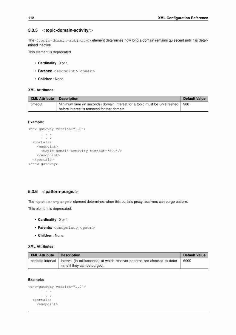
112 XML Configuration Reference
5.3.5 <topic-domain-activity/>
The <topic-domain-activity> element determines how long a domain remains quiescent until it is deter-mined inactive.
This element is deprecated.
• Cardinality: 0 or 1
• Parents: <endpoint> <peer>
• Children: None.
XML Attributes:
XML Attribute Description Default Value
timeout Minimum time (in seconds) domain interest for a topic must be unrefreshedbefore interest is removed for that domain.
900
Example:
<tnw-gateway version="1.0">. . .. . .
<portals><endpoint><topic-domain-activity timeout="800"/>
</endpoint></portals>
</tnw-gateway>
5.3.6 <pattern-purge/>
The <pattern-purge> element determines when this portal's proxy receivers can purge pattern.
This element is deprecated.
• Cardinality: 0 or 1
• Parents: <endpoint> <peer>
• Children: None.
XML Attributes:
XML Attribute Description Default Value
periodic-interval Interval (in milliseconds) at which receiver patterns are checked to deter-mine if they can be purged.
6000
Example:
<tnw-gateway version="1.0">. . .. . .
<portals><endpoint>

5.3 Deprecated Elements 113
<pattern-purge periodic-interval="5000"/></endpoint>
</portals></tnw-gateway>
5.3.7 <pattern-interest-generate/>
The <pattern-interest-generate> element determines timing characteristics for interest message gen-eration at this portal.
This element is deprecated.
• Cardinality: 0 or 1
• Parents: <endpoint> <peer>
• Children: None.
XML Attributes:
XML Attribute Description Default Value
interval Interval (in milliseconds) between groups of patterns. 200
max-patterns Maximum patterns for which interest is generated at one time. 300000
periodic-interval Interval (in milliseconds) at which pattern interest is generated. 300000
Example:
<tnw-gateway version="1.0">. . .. . .
<portals><endpoint><pattern-interest-generate periodic-interval="250000"/>
</endpoint></portals>
</tnw-gateway>
5.3.8 <pattern-domain-activity/>
The <pattern-domain-activity> element determines how long a domain remains quiescent until it isdetermined inactive.
This element is deprecated.
• Cardinality: 0 or 1
• Parents: <endpoint> <peer>
• Children: None.
XML Attributes:

114 XML Configuration Reference
XML Attribute Description Default Value
timeout Minimum time (in seconds) domain interest for a pattern must be unrefreshedbefore interest is removed for that domain.
900
Example:
<tnw-gateway version="1.0">. . .. . .
<portals><endpoint><pattern-domain-activity timeout="800"/>
</endpoint></portals>
</tnw-gateway>
5.3.9 <topic-use-check/>
The <topic-use-check> element checks for interest in topics at periodic intervals.
This element is deprecated.
• Cardinality: 0 or 1
• Parents: <peer>
• Children: None.
XML Attributes:
XML Attribute Description Default Value
periodic-interval The interval (in milliseconds) at which source topics are checked to deter-mine if there is no more interest. Before changing the value of this option,please contact Informatica Support.
300000
Example:
<tnw-gateway version="1.0">. . .. . .
<portals><peer><topic-use-check periodic-interval="1000"/>
</peer></portals>
</tnw-gateway>
5.3.10 <pattern-use-check/>
The <pattern-use-check> element checks for interest in patterns at periodic intervals.
This element is deprecated.

5.3 Deprecated Elements 115
• Cardinality: 0 or 1
• Parents: <peer>
• Children: None.
XML Attributes:
XML Attribute Description Default Value
periodic-interval The interval (in milliseconds) at which source pattern are checked to deter-mine if there is no more interest. Before changing the value of this option,please contact Informatica Support.
300000
Example:
<tnw-gateway version="1.0">. . .. . .
<portals><peer><topic-use-check periodic-interval="1000"/>
</peer></portals>
</tnw-gateway>
5.3.11 <publishing-interval>
The <publishing-interval> element configures the rate at which Daemon Statistics messages are pub-lished. See Daemon Statistics for general information on Daemon Statistics.
• Cardinality: 0 or 1
• Parents: <daemon-monitor>, <endpoint>, <peer>
• Children: <group>
XML Attributes: None.
Example:
<tnw-gateway version="1.0"><daemon>
<daemon-monitor topic="umrouter.1"><lbm-config>/path/umrouter_monitor.cfg</lbm-config><publishing-interval><group name="default" ivl="5"><group name="gateway-config" ivl="30"><group name="portal-config" ivl="30">
</publishing-interval>. . .
</daemon-monitor></daemon>
. . .
. . .</tnw-gateway>

116 XML Configuration Reference
5.3.12 <group>
The <group> element configures the rate at which one particular grouping of Daemon Statistics messages arepublished. See Daemon Statistics for general information on Daemon Statistics.
• Cardinality: 0 or 1
• Parents: <publishing-interval>
• Children: none.
XML Attributes: None.
Example:
<tnw-gateway version="1.0"><daemon>
<daemon-monitor topic="umrouter.1"><lbm-config>/path/umrouter_monitor.cfg</lbm-config><publishing-interval><group name="default" ivl="5"><group name="gateway-config" ivl="30"><group name="portal-config" ivl="30">
</publishing-interval>. . .
</daemon-monitor></daemon>
. . .
. . .</tnw-gateway>
5.4 UM Router Configuration DTD
Here is the XML configuration DTD with the comments removed. To see the DTD with comments included, entertnwgd --dump-dtd.
<!ELEMENT tnw-gateway (daemon?, portals)><!ATTLIST tnw-gateway
version (1.0) #REQUIRED><!ELEMENT daemon (name?, log?, uid?, gid?, pidfile?, lbm-license-file?, topicmap?,
patternmap?, monitor?, web-monitor?, daemon-monitor?, propagation-delay?,xml-config?, route-info?, route-recalculation?)>
<!ELEMENT log ( #PCDATA )><!ATTLIST log
type (file | syslog | console) "console"frequency (disable | daily | hourly | test) "disable"size CDATA " 0 "xml:space (default | preserve) "default"
><!ELEMENT pidfile ( #PCDATA )><!ATTLIST pidfile xml:space (default | preserve) "default"><!ELEMENT uid ( #PCDATA )><!ELEMENT gid ( #PCDATA )><!ELEMENT lbm-license-file ( #PCDATA )><!ATTLIST lbm-license-file xml:space (default | preserve) "default"><!ELEMENT topicmap EMPTY><!ATTLIST topicmap
hash-function ( classic | djb2 | sdbm | murmur2 ) "murmur2"

5.4 UM Router Configuration DTD 117
size CDATA " 131111 "><!ELEMENT patternmap EMPTY><!ATTLIST patternmap
hash-function ( classic | djb2 | sdbm | murmur2 ) "murmur2"size CDATA " 131111 "
><!ELEMENT portals (endpoint | peer)+><!ELEMENT endpoint (name, domain-id, cost?, source-deletion-delay?, max-queue?,
smart-batch?, lbm-config?, lbm-attributes?, acl?, topic-resolution?,late-join?, topic-purge?, topic-interest-generate?, topic-domain-activity?,pattern-purge?, pattern-interest-generate?, pattern-domain-activity?,remote-topic?, remote-pattern?, source-context-name?, receiver-context-name?,sqn-window?, context-query?, publishing-interval? )>
<!ELEMENT peer (name, cost?, sourcemap?, (tcp | single-tcp),source-deletion-delay?, max-queue?, smart-batch?, max-datagram?, batching?,lbm-config?, lbm-attributes?, acl?, topic-purge?, topic-interest-generate?,topic-domain-activity?, pattern-purge?, pattern-interest-generate?,pattern-domain-activity?, topic-use-check?, pattern-use-check?,source-context-name?, receiver-context-name?, sqn-window?, context-query?,gateway-keepalive?, publishing-interval? )>
<!ELEMENT name ( #PCDATA )><!ATTLIST name xml:space (default | preserve) "default"><!ELEMENT domain-id ( #PCDATA )><!ELEMENT cost ( #PCDATA )><!ELEMENT source-deletion-delay ( #PCDATA )><!ELEMENT sourcemap EMPTY><!ATTLIST sourcemap
size CDATA " 131072 "><!ELEMENT tcp (interface?, listen-port, receive-buffer?, send-buffer?, keepalive?,
nodelay?, compression?, tls?, companion )><!ELEMENT interface ( #PCDATA )><!ELEMENT listen-port ( #PCDATA )><!ELEMENT receive-buffer ( #PCDATA )><!ELEMENT send-buffer ( #PCDATA )><!ELEMENT keepalive EMPTY ><!ELEMENT nodelay EMPTY ><!ELEMENT companion (address, port)><!ELEMENT compression ( #PCDATA )><!ELEMENT tls (certificate, certificate-key, certificate-key-password?,
trusted-certificates?, cipher-suites? )><!ELEMENT certificate ( #PCDATA )><!ELEMENT certificate-key ( #PCDATA )><!ELEMENT certificate-key-password ( #PCDATA )><!ELEMENT trusted-certificates ( #PCDATA )><!ELEMENT cipher-suites ( #PCDATA )><!ATTLIST companion
reconnect-interval CDATA " 5000 "><!ELEMENT address ( #PCDATA )><!ELEMENT port ( #PCDATA )><!ELEMENT single-tcp (interface?, receive-buffer?, send-buffer?, keepalive?,
nodelay?, compression?, tls?, (initiator | acceptor ) )><!ELEMENT initiator (address, port)><!ATTLIST initiator
reconnect-interval CDATA " 5000 "><!ELEMENT acceptor (listen-port)><!ELEMENT max-queue ( #PCDATA )><!ELEMENT smart-batch ( #PCDATA )><!ELEMENT max-datagram ( #PCDATA )><!ELEMENT batching (min-length?, batch-interval?)>

118 XML Configuration Reference
<!ELEMENT min-length ( #PCDATA )><!ELEMENT batch-interval ( #PCDATA )><!ELEMENT lbm-config ( #PCDATA )><!ATTLIST lbm-config xml:space (default | preserve) "default"><!ELEMENT lbm-attributes (option+)><!ELEMENT option EMPTY><!ATTLIST option
scope (receiver | context | source | wildcard_receiver | event_queue)#REQUIRED
name CDATA #REQUIREDvalue CDATA #REQUIRED
><!ELEMENT acl (inbound?, outbound?)><!ELEMENT inbound (ace+)><!ELEMENT outbound (ace+)><!ELEMENT ace (topic | pcre-pattern | regex-pattern | transport | source-ip |
multicast-group | udp-source-port | udp-destination-port | tcp-source-port |xport-id)+ >
<!ATTLIST ace match (accept | reject) #REQUIRED ><!ELEMENT topic ( #PCDATA )><!ATTLIST topic
xml:space (default | preserve) "default"><!ELEMENT pcre-pattern ( #PCDATA )><!ATTLIST pcre-pattern
xml:space (default | preserve) "default"><!ELEMENT regex-pattern ( #PCDATA )><!ATTLIST regex-pattern
xml:space (default | preserve) "default"><!ELEMENT transport EMPTY><!ATTLIST transport
value (tcp | lbt-rm | lbtrm | lbt-ru | lbtru | lbt-ipc | lbtipc) #REQUIREDcomparison (eq | equal | ne | notequal) #REQUIRED
><!ELEMENT source-ip EMPTY><!ATTLIST source-ip
value CDATA #REQUIREDcomparison (eq | equal | ne | notequal | lt | lessthan | le |
lessthanequal | gt | greaterthan | ge | greaterthanequal) #REQUIRED><!ELEMENT multicast-group EMPTY><!ATTLIST multicast-group
value CDATA #REQUIREDcomparison (eq | equal | ne | notequal | lt | lessthan | le |
lessthanequal | gt | greaterthan | ge | greaterthanequal) #REQUIRED><!ELEMENT udp-source-port EMPTY><!ATTLIST udp-source-port
value CDATA #REQUIREDcomparison (eq | equal | ne | notequal | lt | lessthan | le |
lessthanequal | gt | greaterthan | ge | greaterthanequal) #REQUIRED><!ELEMENT udp-destination-port EMPTY><!ATTLIST udp-destination-port
value CDATA #REQUIREDcomparison (eq | equal | ne | notequal | lt | lessthan | le |
lessthanequal | gt | greaterthan | ge | greaterthanequal) #REQUIRED><!ELEMENT tcp-source-port EMPTY><!ATTLIST tcp-source-port
value CDATA #REQUIRED
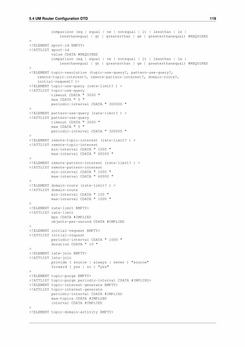
5.4 UM Router Configuration DTD 119
comparison (eq | equal | ne | notequal | lt | lessthan | le |lessthanequal | gt | greaterthan | ge | greaterthanequal) #REQUIRED
><!ELEMENT xport-id EMPTY><!ATTLIST xport-id
value CDATA #REQUIREDcomparison (eq | equal | ne | notequal | lt | lessthan | le |
lessthanequal | gt | greaterthan | ge | greaterthanequal) #REQUIRED><!ELEMENT topic-resolution (topic-use-query?, pattern-use-query?,
remote-topic-interest?, remote-pattern-interest?, domain-route?,initial-request? )>
<!ELEMENT topic-use-query (rate-limit? ) ><!ATTLIST topic-use-query
timeout CDATA " 3000 "max CDATA " 5 "periodic-interval CDATA " 300000 "
><!ELEMENT pattern-use-query (rate-limit? ) ><!ATTLIST pattern-use-query
timeout CDATA " 3000 "max CDATA " 5 "periodic-interval CDATA " 300000 "
><!ELEMENT remote-topic-interest (rate-limit? ) ><!ATTLIST remote-topic-interest
min-interval CDATA " 1000 "max-interval CDATA " 60000 "
><!ELEMENT remote-pattern-interest (rate-limit? ) ><!ATTLIST remote-pattern-interest
min-interval CDATA " 1000 "max-interval CDATA " 60000 "
><!ELEMENT domain-route (rate-limit? ) ><!ATTLIST domain-route
min-interval CDATA " 100 "max-interval CDATA " 1000 "
><!ELEMENT rate-limit EMPTY><!ATTLIST rate-limit
bps CDATA #IMPLIEDobjects-per-second CDATA #IMPLIED
><!ELEMENT initial-request EMPTY><!ATTLIST initial-request
periodic-interval CDATA " 1000 "duration CDATA " 10 "
><!ELEMENT late-join EMPTY><!ATTLIST late-join
provide ( source | always | never ) "source"forward ( yes | no ) "yes"
><!ELEMENT topic-purge EMPTY><!ATTLIST topic-purge periodic-interval CDATA #IMPLIED><!ELEMENT topic-interest-generate EMPTY><!ATTLIST topic-interest-generate
periodic-interval CDATA #IMPLIEDmax-topics CDATA #IMPLIEDinterval CDATA #IMPLIED
><!ELEMENT topic-domain-activity EMPTY>

120 XML Configuration Reference
<!ATTLIST topic-domain-activity timeout CDATA #IMPLIED><!ELEMENT pattern-purge EMPTY><!ATTLIST pattern-purge periodic-interval CDATA #IMPLIED><!ELEMENT pattern-interest-generate EMPTY><!ATTLIST pattern-interest-generate
periodic-interval CDATA #IMPLIEDmax-patterns CDATA #IMPLIEDinterval CDATA #IMPLIED
><!ELEMENT pattern-domain-activity EMPTY><!ATTLIST pattern-domain-activity timeout CDATA #IMPLIED><!ELEMENT remote-topic EMPTY><!ATTLIST remote-topic
check-interval CDATA " 90000 "max-topics CDATA " 100 "timeout CDATA " 300000 "
><!ELEMENT remote-pattern EMPTY><!ATTLIST remote-pattern
check-interval CDATA " 90000 "max-patterns CDATA " 100 "timeout CDATA " 300000 "
><!ELEMENT topic-use-check EMPTY><!ATTLIST topic-use-check periodic-interval CDATA #IMPLIED><!ELEMENT pattern-use-check EMPTY><!ATTLIST pattern-use-check periodic-interval CDATA #IMPLIED><!ELEMENT monitor (transport-module?, format-module?)><!ATTLIST monitor
interval CDATA " 0 "><!ELEMENT transport-module EMPTY><!ATTLIST transport-module
module (lbm | lbmsnmp | udp) "lbm"options CDATA #IMPLIED
><!ELEMENT format-module EMPTY><!ATTLIST format-module
module (csv) "csv"options CDATA #IMPLIED
><!ELEMENT web-monitor ( #PCDATA )><!ATTLIST web-monitor xml:space (default | preserve) "default"><!ELEMENT propagation-delay EMPTY><!ATTLIST propagation-delay delta CDATA #IMPLIED><!ELEMENT xml-config ( #PCDATA )><!ATTLIST xml-config xml:space (default | preserve) "default"><!ELEMENT source-context-name ( #PCDATA )><!ATTLIST source-context-name xml:space (default | preserve) "default"><!ELEMENT receiver-context-name ( #PCDATA )><!ATTLIST receiver-context-name xml:space (default | preserve) "default"><!ELEMENT sqn-window EMPTY><!ATTLIST sqn-window
size CDATA " 16384 "increment CDATA " 2048 "
><!ELEMENT context-query EMPTY><!ATTLIST context-query
periodic-interval CDATA #IMPLIEDmax-contexts CDATA #IMPLIEDinterval CDATA #IMPLIEDtimeout CDATA #IMPLIED
>

5.4 UM Router Configuration DTD 121
<!ELEMENT gateway-keepalive EMPTY><!ATTLIST gateway-keepalive
idle ( yes | no ) "yes"interval CDATA " 5000 "timeout CDATA " 15000 "
><!ELEMENT route-info EMPTY><!ATTLIST route-info
propagation-interval CDATA " 1000 "check-interval CDATA " 750 "timeout CDATA " 4000 "max-hop-count CDATA " 100 "
><!ELEMENT route-recalculation EMPTY><!ATTLIST route-recalculation
backoff-interval CDATA " 5000 "warning-interval CDATA " 10000 "
><!ELEMENT daemon-monitor (lbm-config?, publishing-interval?,
remote-snapshot-request?, remote-config-changes-request?)><!ATTLIST daemon-monitor topic CDATA " tnwgd.monitor "><!ELEMENT publishing-interval (group+)><!ELEMENT group EMPTY><!ATTLIST group name (default | gateway-config | route-manager-topology |
malloc-info | portal-config | portal-stats ) #REQUIRED><!ATTLIST group ivl CDATA #REQUIRED><!ELEMENT remote-snapshot-request EMPTY><!ATTLIST remote-snapshot-request allow (0 | 1) "0"><!ELEMENT remote-config-changes-request EMPTY><!ATTLIST remote-config-changes-request allow (0 | 1) "0">

122 XML Configuration Reference

Chapter 6
UM Router Daemon Statistics
This section contains details on the UM Router's Daemon Statistics feature. You should already be familiar withthe general information contained in Daemon Statistics.
6.1 UM Router Daemon Statistics Structures
The different message types are:
• TNWG_DSTATTYPE_MALLINFO
• TNWG_DSTATTYPE_GATEWAYCFG
• TNWG_DSTATTYPE_PORTCFG
• TNWG_DSTATTYPE_RM_LOCAL
• TNWG_DSTATTYPE_RM_PORTAL
• TNWG_DSTATTYPE_RM_OTHERGW
• TNWG_DSTATTYPE_RM_OTHERGW_NBR
• TNWG_DSTATTYPE_PORTSTAT
Each one has a specific structure associated with it, as detailed in tnwgdmonmsgs.h.
Note that message types ending with "CFG" are in the config category. All others are in the stats category. SeeDaemon Statistics Structures for information on how the two categories are handled differently.
6.1.1 UM Router Daemon Statistics Byte Swapping
A monitoring application receiving these messages must detect if there is an endian mismatch (see Daemon Statis-tics Binary Data). The header structure tnwg_dstat_msg_hdr_t contains a 16-bit field named magic which isset equal to LBM_TNWG_DAEMON_MAGIC. The receiving application should compare it to LBM_TNWG_DAE←↩MON_MAGIC and LBM_TNWG_DAEMON_ANTIMAGIC. Anything else would represent a serious problem.
If the receiving app sees:
magic == LBM_TNWG_DAEMON_MAGIC
124 UM Router Daemon Statistics
then it can simply access the binary fields directly. However, if it sees:
magic == LBM_TNWG_DAEMON_ANTIMAGIC
then most (but not all) binary fields need to be byte-swapped. See tnwgdmon.c for an example, paying specialattention to the macros COND_SWAPxx (which conditionally swaps based on the magic test) and the functionsbyte_swapXX() (which performs the byte swapping).
6.1.2 UM Router Daemon Statistics String Buffers
UM Router Daemon Statistics data structures sometimes contain string buffers. Strings in these data structuresare always null-terminated. These messages are generally sent as fixed-length equal to the sizes of the structures,and therefore include all of the declared bytes of the string fields, even if the contained string uses fewer bytes thandeclared. For example, the structure tnwg_dstat_record_hdr_t contains the field tnwg_dstat_record_hdr_t_←↩stct::portal_name which is a char array of size TNWG_DSTAT_MAX_PORTAL_NAME_LEN. If portal_nameis set to "p1", then only 3 bytes of the buffer are used (including the null string terminator). However, all TN←↩WG_DSTAT_MAX_PORTAL_NAME_LEN bytes will be sent in the TNWG_DSTATTYPE_RM_PORTAL messagetype.
Contrast this with Store Daemon Statistics String Buffers.
There are two exceptions to this rule: TNWG_DSTATTYPE_PORTCFG and TNWG_DSTATTYPE_GATEWAYC←↩FG.
The TNWG_DSTATTYPE_PORTCFG message is of type tnwg_pcfg_stat_grp_msg_t and has the field tnwg←↩_pcfg_stat_grp_msg_t_stct::data. This field is a variable-length string buffer which contains one or more null-terminated strings. The total length of the TNWG_DSTATTYPE_PORTCFG message is the sum of the length ofits sub-structures plus the number of bytes of string data (characters plus string-terminating nulls). The number ofstrings in tnwg_pcfg_stat_grp_msg_t_stct::data is given by tnwg_pcfg_stat_grp_msg_t_stct::rechdr->num←↩_options. The monitoring application must step through the string buffer that many times to find each string. For anexample of how to do this, see tnwgdmon.c in the code following, "‘case TNWG_DSTATTYPE_PORTCFG:‘".
The TNWG_DSTATTYPE_GATEWAYCFG message is of type tnwg_dstat_gatewaycfg_msg_t and has the fieldtnwg_dstat_gatewaycfg_msg_t_stct::data. This field is a variable-length string buffer which contains exactlyone null-terminated string. This string contains the entirety of the UM Router's configuration file. The individuallines contain the normal line-ending character(s). The total length of the TNWG_DSTATTYPE_GATEWAYCFGmessage is the length of its sub-structure plus the number of bytes of string data (characters plus string-terminatingnulls).
6.2 UM Router Daemon Statistics Configuration
There are three places in the UM Router configuration file that Daemon Statistics are configured:
• The <daemon-monitor> element inside the <daemon> definition. Configures all aspects of the StoreDaemon Statistics feature, including publishing intervals.
• The <publishing-interval> element inside the <peer> definition. Configures only the publishing intervalson a peer portal basis.
• The <publishing-interval> element inside the <endpoint> definition. Configures only the publishing in-tervals on an endpoint portal basis.
Here is an example of configuring daemon statistics.

6.3 UM Router Daemon Statistics Requests 125
<?xml version="1.0" encoding="UTF-8" ?><!-- G1 xml file- 2 endpoint portals --><tnw-gateway version="1.0">
<daemon>...<publishing-interval><group name="default" ivl="3"/><group name="gateway-config" ivl="120"><group name="portal-config" ivl="120">
</publishing-interval><remote-snapshot-request allow="1"/><remote-config-changes-request allow="1"/>
</daemon><portals>
<endpoint><name>G1-TRD1</name>...<publishing-interval>
<group name="default" ivl="6"/><group name="gateway-config" ivl="120"><group name="portal-config" ivl="120">
</publishing-interval></endpoint>...
</portals></tnw-gateway>
In this example, all stats-type messages are (conditionally) published on a 3-second interval, except those of portalG1-TRD1, which are published (conditionally) on a 6-second interval. All config-type messages are published(unconditionally) on a 120-second interval.
6.3 UM Router Daemon Statistics Requests
The UM Router Daemon supports a monitoring application to send a specific set of requests to control the operationof Daemon Statistics. The remote-snapshot-request and remote-config-changes-request configuration elementscontrol whether the Store enables this request feature (defaults to disabled).
If enabled, the monitoring application can send a command message to the UM Router in the form of a topiclessunicast immediate "request" message (see lbm_unicast_immediate_request() with NULL for topic). The formatof the message is a simple ascii string, with or without null termination. Due to the simple format of the message,no data structure is defined for it.
When the UM Router receives and validates the command, it sends a UM response message back to the requestingapplication containing a status message (which is not null-terminated). If the status was OK, the Store also performsthe requested action.
The example program tnwgdcmd.c demonstrates the correct way to send the messages and receive the re-sponses.
Commands enabled by remote-snapshot-request:
version
The UM Router returns in its command response the value of LBM_UMESTORE_DMON_VERSION. No dae-mon statistics messages are published.
snap mallinfo
The UM Router immediately publishes the memory allocation usage message of type TNWG_DSTATTYPE←↩_MALLINFO.

126 UM Router Daemon Statistics
snap pstat
The UM Router immediately publishes the portal statistics message(s) of type TNWG_DSTATTYPE_PORT←↩STAT.
snap ri
The UM Router immediately publishes the route information message(s) of types TNWG_DSTATTYPE_RM←↩_LOCAL, TNWG_DSTATTYPE_RM_PORTAL TNWG_DSTATTYPE_RM_OTHERGW, and TNWG_DSTA←↩TTYPE_RM_OTHERGW_NBR.
snap gcfg
The UM Router immediately publishes the gateway configuration message TNWG_DSTATTYPE_GATEWA←↩YCFG.
snap pcfg
The UM Router immediately publishes the portal configuration message(s) TNWG_DSTATTYPE_PORTCFG.
Commands enabled by remote-config-changes-request:
mallinfo N
Set the publishing interval for memory allocation usage.For example: mallinfo 5
ri N
Set the publishing interval for the route information messages.For example: ri 5
gcfg N
Set the publishing interval for the gateway configuration message.For example: gcfg 5
pstat N
Set the publishing interval for the portal statistics messages. This command can be preceded by a portal namein double quote marks to only set the publishing interval for that portal.For example: "G1-TRD1" pstat 5
pcfg N
Set the publishing interval for the portal configuration messages. This command can be preceded by a portalname in double quote marks to only set the publishing interval for that portal.For example: "G1-TRD1" pcfg 5

Chapter 7
UM Router Monitoring
7.1 Router Web Monitor
The built-in web monitor (configured in the tnwgd XML configuration file; see XML Configuration Reference) providesvaluable statistics about the UM Router and its portals, for which, the Web Monitor separates into receive statisticsand send statistics. The Web Monitor provides a page for each endpoint and peer portal.
7.1.1 Main Page
This page displays general information about the UM Router, and also provides the following links to more detailedstatistical and configuration information.
UM Router Configuration
Displays the UM Router XML configuration file used by this UM Router.
Portals
Displays portal statistics and information, one portal per page. The Portals page allows you to link to any of thePeer or Endpoint portals configured for the UM Router.
Topology Info
This links to a page that displays UM Router network connectivity information from the perspective of this UMRouter.
Path Info
This lets you query and display a hop path that messages will take between any two TRDs.
On some platforms, the Main page may include a link (GNU malloc info) to a memory allocation display page thatdisplays the following:
arena
Non-mmapped space allocated (bytes)

128 UM Router Monitoring
ordblks
Number of free chunks
hblks
Number of mmapped regions
hblkhd
Space allocated in mmapped regions (bytes)
uordblks
Total allocated space (bytes)
fordblks
Total free space (bytes)
7.1.2 Endpoint Portal Page
The Endpoint Portal Page displays Receive and Send statistics for the selected endpoint portal. Receive statisticspertain to messages entering the portal from its connected TRD. Send statistics pertain to messages sent out tothe TRD.
Click on any of the links at the top of the page to review configuration option values for the portal's UM topicresolution domain. The two columns provide different units of measure for a given statistic type, where the firstcolumn is typically in fragments or messages (depending on the statistic type), and the second column is in bytes.
Endpoint Portal name
Domain ID
The ID for the Topic Resolution Domain (TRD) to which this portal is connected.
Portal Cost
The cost value assigned to this portal.
Local Interest
Totals (listed below) for topics and patterns in this portal's interest list that originated from receivers in theimmediately adjacent TRD.
Topics
Of the local interest total, the number of topics.
PCRE patterns
Of the local interest total, the number of wildcard patterns, using PCRE pattern matching.
REGEX patterns
Of the local interest total, the number of wildcard patterns, using REGEX pattern matching.
Remote Interest
Totals (listed below) for topics and patterns in this portal's interest list that originated from receivers beyond anddownstream from the immediately adjacent TRD.

7.1 Router Web Monitor 129
Topics
Of the remote interest total, the number of topics.
PCRE patterns
Of the remote interest total, the number of wildcard patterns, using PCRE pattern matching.
REGEX patterns
Of the remote interest total, the number of wildcard patterns, using REGEX pattern matching.
Proxy Receivers
The number of proxy receivers active in this portal.
Receiver Topics
The number of topics in which the other portals in the UM Router have detected current interest and summarilypropagated to this portal.
Receiver PCRE patterns
The number of wildcard patterns, using PCRE pattern matching, in which the other portals in the UM Routerhave detected current interest and summarily propagated to this portal.
Receiver REGEX patterns
The number of wildcard patterns, using REGEX pattern matching, in which the other portals in the UM Routerhave detected current interest and summarily propagated to this portal.
Proxy Sources
The number of proxy sources active in this portal.
Endpoint Receive Statistics
Transport topic fragments/bytes received
The total transport-based topic-related traffic of messages containing user data received by this portal froma TRD. The first column counts the number of fragments (or whole messages for messages that were notfragmented).
Transport topic request fragments/bytes received
Topic messages received that are request messages, i.e., messages send via lbm_send_request∗() rather thanlbm_src_send∗().
Transport topic control msgs/bytes received
The total transport-based topic-related traffic received by this portal from a TRD. These are supervisory mes-sages, which include TSNIs, SRIs., etc. The first column counts the number of messages.
Immediate topic fragments/bytes received
The total number of Multicast Immediate Messaging (MIM) messages or message fragments, and bytes (sec-ond column), that have a topic, received at this portal.
Immediate topic request fragments/bytes received
Of the MIM topic messages received, this is the amount of those that are requests.

130 UM Router Monitoring
Immediate topicless fragments/bytes received
The total number of MIM messages or message fragments, and bytes (second column), with null topics, re-ceived by his portal.
Immediate topicless request fragments/bytes received
Of the MIM topicless messages received, this is the amount of those that are requests.
Unicast data messages/bytes received
The total number of Unicast Immediate Messaging (UIM) messages (and bytes, second column) containinguser data, received by this portal.
Duplicate unicast data messages/bytes dropped
UIM data messages discarded because they were duplicates of messages already received.
Unicast data messages/bytes received with no stream info
UIM data messages discarded because they were from an earlier, incompatible version of UM. This tally shouldstay at 0; otherwise, contact Informatica Support.
Unicast data messages/bytes received with no route to destination
UIM data messages that are on a wrong path, possibly due to a route recalculation. This tally should stay at 0,though it may increment a few messages at the time of a topology change.
Unicast control messages/bytes received
The total number of Unicast Immediate Messaging (UIM) supervisory (non-data) messages (and bytes, secondcolumn) received by this portal.
Duplicate unicast control messages/bytes dropped
Supervisory UIMs dropped because they were duplicates of messages already received.
Unicast control messages/bytes received with no stream info
Supervisory UIMs dropped because they were from an earlier, incompatible version of UM. This tally shouldstay at 0; otherwise, contact Informatica Support.
Unicast control messages/bytes received with no route to destination
Supervisory UIM messages that are on a wrong path, possibly due to a route recalculation. This tally shouldstay at 0, though it may increment a few messages at the time of a topology change.
Endpoint Send Statistics
Transport topic fragments/bytes forwarded
The total transport-based topic-related traffic forwarded to this portal from other portals in this UM Router. Thiscould include user messages, TSNIs, SRIs, etc. The first column counts the number of fragments (or wholemessages for messages that were not fragmented).
Transport topic fragments/bytes sent
Of the transport topic traffic forwarded, this is the amount of traffic sent out to the TRD.
Transport topic request fragments/bytes sent
Of the messages sent, this is the amount of those that are requests.

7.1 Router Web Monitor 131
Duplicate transport topic fragments/bytes dropped
Of the messages forwarded to this portal, this is the total of those that were discarded because they wereduplicates of messages already received.
Transport topic fragments/bytes dropped due to blocking
Of the messages forwarded to this portal, this is the amount of those that were discarded because they wereblocked from sending, and were unable to be buffered. Message rates on other portals probably exceeded therate controller limit on this portal.
Transport topic fragments/bytes dropped due to error
Of the messages forwarded to this portal, this is the total of those that were discarded due to an application ornetwork connection failure.
Transport topic fragments/bytes dropped due to fragment size error
Of the messages forwarded to this portal, this is the total of those that were discarded possibly because of aconfiguration error. If this count is not at or near 0, verify that maximum datagram size for all transports is thesame throughout the network.
Immediate topic fragments/bytes forwarded
The total number of Multicast Immediate Messaging (MIM) messages or message fragments, and bytes (sec-ond column), forwarded to this portal from other portals in this UM Router.
Immediate topic fragments/bytes sent
Of the MIM topic messages forwarded to this portal, this is the amount of traffic sent out to the TRD.
Immediate topic request fragments sent
Of the MIM topic messages sent, this is the amount of those that are requests.
Immediate topic fragments/bytes dropped due to blocking
Of the MIM topic messages forwarded to this portal, this is the amount of those that were discarded becausethey were blocked from sending, and were unable to be buffered. Message rates on other portals probablyexceeded the rate controller limit on this portal.
Immediate topic fragments/bytes dropped due to error
Of the MIM topic messages forwarded to this portal, those that were discarded due to an application or networkconnection failure.
Immediate topic fragments/bytes dropped due to fragment size error
Of the MIM topic messages forwarded to this portal, those that were dropped possibly because of a configu-ration error. If this count is not at or near 0, verify that maximum datagram size for all transports is the samethroughout the network.
Immediate topicless fragments/bytes forwarded
The total number of Multicast Immediate Messaging (MIM) messages or message fragments, and bytes (sec-ond column), with null topics, forwarded to this portal from other portals in this UM Router.
Immediate topicless fragments/bytes sent
Of the MIM topicless messages forwarded to this portal, this is the amount of traffic sent out to the TRD.
Immediate topicless request fragments sent
Of the MIM topicless messages sent, this is the amount of those that are requests.

132 UM Router Monitoring
Immediate topicless fragments/bytes dropped due to blocking
Of the MIM topicless messages forwarded to this portal, this is the amount of those that were discarded becausethey were blocked from sending, and were unable to be buffered. Message rates on other portals probablyexceeded the rate controller limit on this portal.
Immediate topicless fragments/bytes dropped due to error
Of the MIM topicless messages forwarded to this portal, those that were discarded due to an application ornetwork connection failure.
Immediate topicless fragments/bytes dropped due to fragment size error
Of the MIM topicless messages forwarded to this portal, those that were dropped possibly because of a config-uration error. If this count is not at or near 0, verify that maximum datagram size for all transports is the samethroughout the network.
Unicast messages/bytes forwarded
The total number of Unicast Immediate Messaging (UIM) messages (and bytes, second column), both controland containing user data, forwarded to this portal.
Unicast messages/bytes sent
Of the UIM data messages forwarded to this portal, this is the amount of traffic sent out to the TRD.
Unicast messages/bytes dropped due to error
Of the UIM data messages forwarded to this portal, those that were discarded due to an application or networkconnection failure.
Current/maximum data bytes enqueued (limit: n)
For bytes in this portal's send buffer (due to a blocking send), the first column is a snapshot of the currentamount, and the second column is a high-water mark. The displayed limit (n) is the configuration value foroption <max-queue>.
7.1.3 Peer Portal Page
This page allows you to see Receive and Send statistics for the selected peer portal. Click on any of the links at thetop of the page to review configuration option values for the portal's UM topic resolution domain.
The peer portal page displays the following statistics:
Peer Portal name
Portal Cost
The cost value assigned to this portal.
Interest
Totals (listed below) for topics and patterns in this portal's interest list that originated from receivers beyond anddownstream from the immediately adjacent UM Router.
Topics
Of the interest total, the number of topics.

7.1 Router Web Monitor 133
PCRE patterns
Of the interest total, the number of wildcard patterns, using PCRE pattern matching.
REGEX patterns
Of the interest total, the number of wildcard patterns, using REGEX pattern matching.
Proxy Receivers
The number of proxy receivers active in this portal.
Receiver topics
All topics in which the other portals in the UM Router have detected current interest and summarily propagatedto this portal.
Receiver PCRE patterns
All wildcard patterns, using PCRE pattern matching, in which the other portals in the UM Router have detectedcurrent interest and summarily propagated to this portal.
Receiver REGEX patterns
All wildcard patterns, using REGEX pattern matching, in which the other portals in the UM Router have detectedcurrent interest and summarily propagated to this portal.
Proxy Sources
The number of proxy sources active in this portal.
Peer Receive Statistics
Data messages/bytes received
The total of messages containing data received at this portal. The first column counts the number of fragments(or whole messages for messages that were not fragmented).
Transport topic fragment data messages/bytes received
The total of user-data messages received on any topic resolved through this portal. The first column counts thenumber of fragments (or whole messages for messages that were not fragmented).
Transport topic fragment data messages/bytes received with unknown source
Topic messages received whose source this UM Router has not seen before.
Transport topic request fragment data messages/bytes received
These are topic messages received that are request messages, i.e., messages send via lbm_send_request∗()rather than lbm_src_send∗().
Transport topic request fragment data messages/bytes received with unknown source
Of the request messages received, the topic messages received whose source this UM Router has not seenbefore.
Immediate topic fragments/bytes received
The total number of Multicast Immediate Messaging (MIM) messages or message fragments, and bytes (sec-ond column), that have a topic, received by all proxy receivers at this portal.

134 UM Router Monitoring
Immediate topic request fragments/bytes received Of the MIM topic messages received, this is the total of thosethat are requests.
Immediate topicless fragments/bytes received
The total number of MIM messages or message fragments, and bytes (second column), with null topics, re-ceived by all proxy receivers at this portal.
Immediate topicless request fragments/bytes received
Of the MIM topicless messages received, this is the total of those that are requests.
Unicast data messages/bytes received
The total number of Unicast Immediate Messaging (UIM) messages (and bytes, second column) containinguser data, received by this portal.
Unicast data messages/bytes received with no stream information
UIM data messages discarded because they were from an earlier, incompatible version of UM. This tally shouldstay at 0; otherwise, contact Informatica Support.
Unicast data messages/bytes received with no route to destination
UIM data messages that are on a wrong path, possibly due to a route recalculation. This tally should stay at 0,though it may increment a few messages at the time of a topology change.
Control messages/bytes received
The total of supervisory messages (containing no data) received at this portal.
Transport topic control messages/bytes received
Of the control messages received, those that are transport/topic based (such as TSNIs, SRIs., etc.).
Transport topic control messages/bytes received with unknown source
Of the transport/topic control messages received whose source this UM Router has not seen before.
Unicast control messages/bytes received
The total number of Unicast Immediate Messaging (UIM) supervisory (non-data) messages (and bytes, secondcolumn) received by this portal.
Retransmission requests/bytes received
Supervisory UIMs that are requests for retransmission of lost (or Late Join) messages.
Control messages/bytes received with no stream info
Supervisory UIMs discarded because they were from an earlier, incompatible version of UM. This tally shouldstay at 0; otherwise, contact Informatica Support.
Control messages/bytes received with no route to destination
Supervisory UIM messages that are on a wrong path, possibly due to a route recalculation.
Gateway control messages/bytes received
The total of UM Router-only, peer-to-peer supervisory messages received at this portal.
Unhandled control messages/bytes received
Supervisory UIMs discarded because, though they are well-formed, they have no valid action request. Thistally should stay at 0; otherwise, contact Informatica Support.

7.1 Router Web Monitor 135
Peer Send Statistics
Transport topic fragments/bytes forwarded
The total transport-based topic-related traffic forwarded to this portal from other portals in this UM Router. Thiscould include user messages, TSNIs, SRIs., etc. The first column counts the number of fragments (or wholemessages for messages that were not fragmented).
Transport topic fragments/bytes sent
Of transport topic messages forwarded to this portal, the amount of traffic sent to the adjacent UM Router.
Transport topic request fragments/bytes sent
Of transport topic messages sent, those that were request messages.
Transport topic fragments/bytes dropped (duplicate)
Of transport topic messages forwarded to this portal, messages discarded because they were duplicates ofmessages already received.
Transport topic fragments/bytes dropped (blocking)
Of transport topic messages forwarded to this portal, this is the amount of those that were discarded becausethey were blocked from sending, probably due to TCP flow control, and were unable to be buffered. The UMRouter's XML configuration file may need to be adjusted.
Transport topic fragments/bytes dropped (not operational)
Of transport topic messages forwarded to this portal, messages discarded because the peer link is down.
Transport topic fragments/bytes dropped (queue failure)
Of transport topic messages forwarded to this portal, messages discarded due to a memory allocation failure.
Unicast messages/bytes forwarded
The total number of supervisory (no data payloads) Unicast Immediate Messaging (UIM) messages (and bytes,second column) forwarded to this portal from other portals in this UM Router. These messages can be eithercontrol (supervisory) messages or contain user data.
Unicast messages/bytes sent
Of the UIMs forwarded to this portal, the amount of traffic sent to the adjacent UM Router.
Unicast messages/bytes dropped (blocking)
Of the UIMs forwarded to this portal, this is the amount of those that were discarded because they wereblocked from sending, probably due to TCP flow control, and were unable to be buffered. The UM Router'sXML configuration file may need to be adjusted.
Unicast messages/bytes dropped (not operational)
Of the UIMs forwarded to this portal, messages discarded because the peer link is down.
Unicast messages/bytes dropped (queue failure)
Of the UIMs forwarded to this portal, messages discarded due to a memory allocation failure.
Gateway control messages/bytes sent
The total number of UM Router supervisory messages (and bytes, second column), generated at this portal.

136 UM Router Monitoring
Gateway control messages/bytes sent Of the UM Router supervisory messages generated, the number sent to theadjacent UM Router.
Gateway control messages/bytes dropped (blocking) The amount of UM Router supervisory messages that werediscarded because they were blocked from sending, probably due to TCP flow control, and were unable to bebuffered. The UM Router's XML configuration file may need to be adjusted.
Gateway control messages/bytes dropped (not operational)
The amount of UM Router supervisory messages that were discarded because the peer link was down.
Gateway control messages/bytes dropped (queue failure)
The amount of UM Router supervisory messages that were discarded due to a memory allocation failure.
Batches
The number of times messages were batched.
Minimum messages/bytes per batch
The lowest recorded number of messages in a batch, and the number of bytes in that batch.
Average messages/bytes per batch
The average number of messages in a batch, and the number of bytes in that average batch.
Maximum messages/bytes per batch
The highest recorded number of messages in a batch, and the number of bytes in that batch.
Current/maximum data bytes enqueued
For bytes in this portal's send buffer (due to a blocking send), the first column is a snapshot of the currentamount, and the second column is a high-water mark. The displayed limit is the configuration value for option<max-queue>.
Keepalive/RTT samples
The number of keepalive messages that have been set to the other UM Router's portal and responded to.
Minimum RTT (microseconds)
Of the keepalives sent and responded to, the lowest recorded round-trip time.
Mean RTT (microseconds)
Of the keepalives sent and responded to, the mean recorded round-trip time.
Maximum RTT (microseconds)
Of the keepalives sent and responded to, the highest recorded round-trip time.
Last keepalive responded to
The send timestamp (date and time) of the last sent keepalive message that was responded to.

7.1 Router Web Monitor 137
7.1.4 Topology Info Page
This page allows you to see UM Router network connectivity information from the perspective of this UM Router.The Other UM Routers section (below) provides information in the same format as is used for the local UM Router.
Local UM Router Name
The UM Router name as assigned via configuration.
Local UM Router ID
A unique value that the UM Router assigns to itself automatically.
Self Version
A configuration version for this UM Router, as seen collectively by the UM Router network.
Topology Signature
An identifier for the "map" of this UM Router network's routes. This value should be the same for all UM Routers.
Last recalc duration
The amount of time in seconds that it took this UM Router to perform its most recent route recalculation.
Graph Version
The number of times this UM Router has updated its view of the topology.
UM Router Count
The number of UM Routers in this UM Router network.
Topic Resolution Domain Count
The number of TRDs in this UM Router network.
Portal (endpoint or peer)
This display is repeated for each portal of this UM Router.
Portal Name
The portal's name as assigned via configuration.
Adjacent Domain/UM Router ID
For an endpoint portal, this is the configured <domain-id> for the connected TRD. For a peer portal, this is anautomatically assigned unique identifier for the connected UM Router.
Cost
This portal's configured cost.
Last interest recalc duration
The amount of time in seconds that it took this UM Router to perform a recalculation that resulted in an updateto the interest status for this portal.
Last proxy receiver recalc duration
The amount of time in seconds that it took this UM Router to perform recalculation that resulted in an update tothe status of proxy receivers (create, maintain, or destroy) for this portal.

138 UM Router Monitoring
Other UM Routers
This display is repeated for each other UM Router in this UM Router's network.
UM Router Name
The UM Router name as assigned via configuration.
UM Router ID
A unique value that the UM Router assigns to itself automatically.
Version
A configuration version for the UM Router, as seen collectively by the UM Router network.
Topology Signature
An identifier for the "map" of this UM Router network's routes. This value should be the same for all UM Routers.
Last Activity n seconds ago
How long since the last time this local UM Router received a route info packet from the designated "other" UMRouter.
Adjacent Domain ID
The configured ID of one of this "other" UM Router's connected TRD, plus the cost assigned to the associateendpoint portal. If there are more than one endpoint portals in the UM Router, this line is repeated for each.
Adjacent UM Router ID
The automatically assigned ID of one of this "other" UM Router's connected UM Router, plus the cost assignedto the associate peer portal. If there are more than one peer portals in the UM Router, this line is repeated foreach.
7.1.5 Path Info
The Path Info page lets you query and display a hop path that messages will take between any two TRDs that youenter into the Domain ID 1 and Domain ID 2 text boxes. Fill in the boxes and click the Calculate Shortest Pathbutton, and you see the following fields:
Hop Count
The number of hops from none node to the next along the displayed route, where a node can be either a UMRouter or a TRD.
Aggregate Cost
A sum of the cost values of all portals along the displayed path.
Path
A display of the UM Router and TRD hops listed in route order from the starting TRD to the ending TRD.

7.2 UM Router Log Messages 139
7.2 UM Router Log Messages
The UM Router daemon generates log messages that are used to monitor its health and operation. You can config-ure these to be directed to "console" (standard output), "syslog", or a specified log "file", via the <log> configurationelement. Normally "console" is only used during testing, as a persistent log file is preferred for production use. TheUM Router does not over-write log files on startup, but instead appends them.
7.2.1 UM Router Rolling Logs
To prevent unbounded disk file growth, the UM Router supports rolling log files. When the log file rolls, the file isrenamed according to the model:CONFIGUREDNAME_PID.DATE.SEQNUMwhere:
• CONFIGUREDNAME - Root name of log file, as configured by user.
• PID - Process ID of the UM Router daemon process.
• DATE - Date that the log file was rolled, in YYYY-MM-DD format.
• SEQNUM - Sequence number, starting at 1 when the process starts, and incrementing each time the log filerolls.
For example: umrouterlog_9867.2017-08-20.2
The user can configure when the log file is eligible to roll over by either or both of two criteria: size and frequency.The size criterion is in millions of bytes. The frequency criterion can be daily or hourly. Once one or both criteria aremet, the next message written to the log will trigger a roll operation. These criteria are supplied as attributes to the<log> configuration element.
If both criteria are supplied, then the first one to be reached will trigger a roll. For example, consider the setting:
<log type="file" size="23" frequency="daily">store.log</log>
Let say that the log file grows at 1 million bytes per hour. At 11:00 pm, the log file will reach 23 million bytes, andwill roll. Then, at 12:00 midnight, the log file will roll again, even though it is only 1 million bytes in size.
Note
The rolling logs cannot be configured to automatically overwrite old logs. Thus, the amount of disk spaceconsumed by log files will grow without bound. The user must implement a desired process of archiving ordeleting older log files according to the user's preference.
7.2.2 Important UM Router Log Messages
Connection Failure Messages
peer portal [name] failed to connect to peer at [IP:port] via [interface] [err]:reason
peer portal [name] failed to accept connection (accept) [err]: reason
Lost Connection Messages

140 UM Router Monitoring
peer portal [name] lost connection to peer at [IP:port] via [interface]peer portal [name] connection destroyed due to socket failurepeer portal [name] detected dropped inbound connection (read) [err]: reasonpeer portal [name] detected dropped inbound connection (zero-len read)
Endpoint Messages
If a UMP store is adjacent to the UM Router, and the UM Router has been restarted, you typically see messages ofthe form:
endpoint portal [name] has no forwarding entry for destination ctxinst [string],dropping msg (lbmc cntl ume)
These messages are normal, and cease when the UM Router has established the forwarding information for thegiven context.
Peer Messages
Acceptor: peer portal [name] received connection from [IP:port]Initiator: peer portal [name] connected to [IP:port ]
7.3 UM Router Transport Stats
Using the <monitor> element in a UM Router's XML configuration file and the UMS Monitoring feature, youcan monitor the transport activity between the UM Router and its Topic Resolution Domain. The configuration alsoprovides Context and Event Queue statistics. The statistics output identifies individual portals by name.

Chapter 8
UM Router Glossary
Access Control List (ACL)
A portal configuration you can use to filter out messages based on a variety of criteria.
forwarding cost
A value assigned to a portal to help determine best-path routing selection.
UM Router keepalive
Control messages exchanged between UM Routers to confirm that UM Routers are still running.
Interest Message
Control messages exchanged between UM Routers to confirm that UM Routers are still running.
Originating Transport ID (OTID)
Unique identifier of a message's transport session at the originating source.
portal
A TCP/IP interface (socket) on a UM Router through which the UM Router passes data. Endpoint portalsinterface TRDs, and peer portals interface peer portals of other UM Routers.
Topic Resolution Domain (TRD)
The realm of UDP multicast or unicast connectivity that allows UM topic resolution to occur. Blocking of thisUDP connectivity (for example, by a firewall or a restrictive WAN link) defines a TRD's boundaries. Contextswithin a TRD must have the same topic resolution configuration option settings (multicast group IP address/portand resolver interface full or CIDR address).
Use Query
A periodic control message distributed to all members of a TRD to verify the continued presence of receiversfor a given topic or pattern.
web monitor
A web-based real-time UM Router statistics and configuration display.

142 UM Router Glossary

Chapter 9
Comparison to Pre-6.0 UM Gateway
With the release of Ultra Messaging 6.0, the UM Gateway feature is discontinued and replaced by the Ultra Mes-saging Dynamic Routing Option (also referred to as the UM Router).
The UM Router's primary improvement over the UM Gateway is its ability to intelligently select efficient traffic routesfrom multiple path choices on a dynamic topic-by-topic basis.
Note
This release of the UM Router is not backward compatible with earlier versions of the UM Gateway in thesense that you cannot have UM Routers and UM Gateways in the same network.
9.1 Added Features and Differences
In addition to routing functionality, the following are features of the UM Router that were not provided in the UMGateway:
• Multi-path, ring, or mesh topologies
• Interoperability with MIM and Persistence (see UM Feature Compatibility for complete feature interoperabilityinformation)
• Ability to restart the UM Router within a transport's activity timeout period
• Reduced topic resolution traffic via more efficient use of Use Queries and Use Query Responses
• The default value for the portal <cost> is 1 (one). 0 (zero) is not a valid cost value.
• The UM Router daemon (tnwgd) logs version information on startup.
• Compression and/or encryption may now be applied to peer links.
The following configuration options exist in the UM Router but not the UM Gateway. See XML Configuration Refer-ence for more information on these options.
• <name> (as a <daemon> child)
• <route-info>
• <route-recalculation>
• <source-deletion-delay>

144 Comparison to Pre-6.0 UM Gateway
• <max-queue>
• <remote-topic-interest>
• <remote-pattern-interest>
• <rate-limit>
• <domain-route>
• <remote-topic>
• <remote-pattern>
• <sourcemap>
• <compression>
• <tls>