dynamic prototype bim manual for visiting quarters · dynamic prototype bim manual for a visiting...
TRANSCRIPT

Developed by:
Air Force Center for Engineering and the Environment
Ralph “Rick” Sinkfield, YD-03, DAF – Project Manager
Email: [email protected]
Dynamic Prototype BIM Manual for a Visiting Quarters – V1.0 January 25, 2012

1
TABLE OF CONTENTS INTRODUCTION
Executive Summary 2
Goals 2
Scope and Use 2-3
Program Assumptions
Kit of Parts GUIDELINE INTEGRATION
Site Design 3-4
Tool Utilization Strategies Siting Requirements Circulation Establishing the Model
Additional Requirements and Integration Concepts Parking & Site Considerations Site Amenities Landscape Architecture
Building Design 4-6
Tool Utilization Strategies Building Configuration Interior/Exterior Relationships Noise Considerations Architecture
Interior Design
Specifications 6-7
Tool Utilization Strategies LEED Checklist 7
Tool Utilization Strategies Software Requirements 7
Additional Requirements LIST OF ILLUSTRATIONS
Figure 1 – Module 1: Standard Guest Room 10 Figure 2 – Module 2: Accessible Guest Room 10 Figure 3 – Module 3: Suite 11 Figure 4 – Module 4: Accessible Suite 11 Figure 5 – Module 5: Guest Laundry/Ice 12 Figure 6 – Module 6: Residential Wing Support 12 Figure 7A – Module 7A: Vestibule & Lobby 12 Figure 7B – Module 7B: Reception/ Retail/ Luggage Storage 13 Figure 7C – Module 7C: Business Center 13 Figure 8 – Module 8: Fitness Room 13 Figure 9 – Module 9: Public Restrooms 14 Figure 10 – Module 10: Conference Room 14 Figure 11 – Module 11: Rickenbacker’s 14 Figure 12 – Module 12: Administration 15 Figure 13 – Module 13: Staff Locker Room 16
2
Figure 14 – Module 14: Staff Break Room 16 Figure 15 – Module 15: Equipment/ Bulk Storage 17 Figure 16 – Module 16: Linen Storage 18 Figure 17 – Module 17: Janitor Areas 18 Figure 18 – Module 18: Service Elevator 19 Figure 19 – Module 19: Maintenance Workshop 19 Figure 20 – Module 20: Receiving Area 19 Figure 21 – Module 21: Electrical Room 20 Figure 22 – Module 22; Mechanical Room 20 Figure 23 – Module 23: Guest Elevator 20 Figure 24 – Module 24: Stairs 21 Figure 25 – Mega Module 1: Residential Wing 22 Figure 26 – Adjacency Diagram - Guest Services 23 Figure 27 – Adjacency Diagram - Administration 23 Figure 28 – Mega Module 2: Guest Services & Administration 24 Figure 29 – Adjacency Diagram - Mega Module 3: Back of House Support 25 Figure 30 – Mega Module 3: Back of House Support 26 Figure 31 – Building: 120-Room Visiting Quarters First Floor Key Plan 27 Figure 32 – Building: 120-Room Visiting Quarters Enlarged First Floor Plan 27 Figure 33 – Building: 120-Room Visiting Quarters Second Floor Key Plan 28 Figure 34 – Building: 120-Room Visiting Quarters Enlarged Second Floor Plan 28 Figure 35 – Building: 200-Room Visiting Quarters First Floor Key Plan 29 Figure 36 – Building: 200-Room Visiting Quarters Enlarged First Floor Plan 29 Figure 37 – Building: 200-Room Visiting Quarters Second Floor Key Plan 30 Figure 38 – Building: 200-Room Visiting Quarters Enlarged Second Floor Plan 30 Figure 39 – Building: 300-Room Visiting Quarters First Floor Key Plan 31 Figure 40 – Building: 300-Room Visiting Quarters Enlarged First Floor Plan 31 Figure 41 – Building: 300-Room Visiting Quarters Second Floor Key Plan 32 Figure 42 – Building: 300-Room Visiting Quarters Enlarged Second Floor Plan 32 Figure 43 – Building: 300-Room Visiting Quarters Third and Fourth Floor Key Plan 33 Figure 44 – Building: 300-Room Visiting Quarters Enlarged 3rd and 4th Floor Plan 33 Figure 45 – File Directory Structure Example 34 Figure 46 – Duplication Example 35 Figure 47 – Group Manipulation Example 35
REFERENCES
AF Services Facilities Design Guide: Visiting Quarters 2010 UFC 4-720-01: Lodging Facilities

3
INTRODUCTION
Executive Summary
The intent of this Dynamic Prototype BIM (Building Information Model) Manual is to describe the process for utilizing the electronic design tool to improve efficiency and effectiveness in the implementation of the Visiting Quarters Design Guide. Dynamic Prototype is a flexible design model that leverages the advantages of BIM to standardize components of a building type (in this case a Visiting Quarters facility) through a schematic 3D model. Design models can vary from performance criteria to prescriptive criteria depending on the number of variables. For visiting quarters the prototype is utilizing a kit-of-parts approach. The kit-of-parts models are broken down into disciplines (Architecture, Structure, Mechanical, Electrical/Telecom, Plumbing, and Fire Suppression). Version 1.0 contains a model for each discipline with many individual modules within each model. Goals
The goal of the BIM prototypes is to communicate vital information from the Visiting Quarters Design Guide as well as lessons learned from other installations in a BIM platform that will allow A/Es to expedite future Visiting Quarters designs. The prototypes help A/Es and prospective users start the conversation about the final design, identify project scope, and discover design options. Scope and Use
In accordance with the Visiting Quarters Design Guide, the kit-of-parts models meet the minimum net living area (NLA) requirements along with the gross module area (GMA) as specified within the VQ Guide Space Planning Spreadsheet. Additional assumptions for the models were made to test the assembly of the kit-of-parts models into a building that meets the gross building area (GBA). Examples of these arrangements can be found on the Mega Module and Building Plans. The assumptions for Version 1.0 are as follows:
1. Program Assumptions Guest room modules include standard guest room, ADA standard guest room,
suite, and ADA suite. 200-room VQ is the basis for conceptual engineering and sizing requirements. All units meet the minimum net living area requirements. Guest services is the most flexible and will require manipulation for site
adaptation and installation-specific functional requirements. Mechanical, Electrical, Telecommunication, and other building utility spaces will
need to be designed and integrated depending upon the location and specific installation requirements in all modules other than the guest rooms and suites.
Structural CMU or steel are the recommended system; however, all building systems should be explored based on installation-specific requirements.
Building envelope systems will be applied based on installation-specific requirements.
All modules have been approved by AFSVA. Any reconfigurations of the units must meet the requirements listed in the Visiting
Quarters Design Guide.
2. Kit of Parts a. Architectural
i. Kit of Parts include: 1. Module 1: Standard Guest Room, Module 2: Accessible Guest
Room, Module 3: Suite, Module 4: Accessible Suite, Module 5: Guest Laundry/ Ice, Module 6: Residential Wing Support, Module 7A: Vestibule 7 Lobby, Module 7B: Reception/Retail/Luggage

4
Storage, Module 7C: Business Center, Module 8: Fitness Room, Module 9: Public Restrooms, Module 10: Conference Room, Module 11: Rickenbacker's, Module 12: Administration, Module 13: Staff Locker Room, Module 14: Staff Break Room, Module 15: Equipment/ Bulk Storage, Module 16: Linen Storage, Module 17: Janitor Areas, Module 18: Service Elevator, Module 19: Maintenance Workshop, Module 20: Receiving Area, Module 20: Utility Rooms, Module 21: Electrical Room, Module 22: Mechanical Room, Module 23: Guest Stairs, Module 24: Stairs, Mega Module 1: Residential Wing Support, Mega Module 2: Guest Services & Administration, and Mega Modules 3: Back of House Support.
ii. Modules1-6 have been included in the design of Mega Module 1, Modules 7-12 and 22-23 have been included in Mega Module 2 and Modules 13-20 have been included in Mega Module 3 as options for a residential wing, guest services/administration, and the back of house support respectively .
iii. It is intended that all modules can be utilized to configure site adapt building floor plans as needed (Refer to Building Plan Examples).
b. Structural
i. Kit of Parts include: 1. Module 1: Standard Guest Room, Module 2: Accessible Guest
Room, Module 3: Suite, Module 4: Accessible Suite, Module 5: Guest Laundry/ Ice, Module 6: Residential Wing Support, Module 7A: Vestibule 7 Lobby, Module 7B: Reception/Retail/Luggage Storage, Module 7C: Business Center, Module 8: Fitness Room, Module 9: Public Restrooms, Module 10: Conference Room, Module 11: Rickenbacker's, Module 12: Administration, Module 13: Staff Locker Room, Module 14: Staff Break Room, Module 15: Equipment/ Bulk Storage, Module 16: Linen Storage, Module 17: Janitor Areas, Module 18: Service Elevator, Module 19: Maintenance Workshop, Module 20: Receiving Area, Module 20: Utility Rooms, Module 21: Electrical Room, Module 22: Mechanical Room, Module 23: Guest Stairs, Module 24: Stairs,
ii. Modules 1-23 will include floor slabs only.
c. Mechanical i. Kit-of-Parts include: Module 1-4 (Hot/Arid, Hot/Humid, and Cold/Arid
climates).
d. Electrical i. Kit-of-Parts include: Module 1-4.
e. Plumbing i. Kit-of-Parts include: Module 1-4.
f. Fire Protection i. Module 1: Standard Guest Room, Module 2: Accessible Guest Room,
Module 3: Suite, Module 4: Accessible Suite, Module 5: Guest Laundry/ Ice, Module 6: Residential Wing Support, Module 7A: Vestibule 7 Lobby, Module 7B: Reception/Retail/Luggage Storage, Module 7C: Business Center, Module 8: Fitness Room, Module 9: Public Restrooms, Module 10: Conference Room, Module 11: Rickenbacker's, Module 12: Administration, Module 13: Staff Locker Room, Module 14: Staff Break

5
Room, Module 15: Equipment/ Bulk Storage, Module 16: Linen Storage, Module 17: Janitor Areas, Module 18: Service Elevator, Module 19: Maintenance Workshop, Module 20: Receiving Area, Module 20: Utility Rooms, Module 21: Electrical Room, Module 22: Mechanical Room, Module 23: Guest Stairs, and Module 24: Stairs.
GUIDELINE INTEGRATION
Site Design
Tool Utilization Strategies
1. Siting Requirements Utilize the kit-of-parts to assemble the initial massing model. Group units before multiplying the units to take advantage of BIM. Configure model to the appropriate site dimensions and established setback
requirements listed in the Visiting Quarters Design Guide and other references. After multiplying units into assembled massing model, “exclude” duplicated
elements such as party-walls (Refer to Figure 46 for Duplication Example). 2. Circulation
Ideas and concepts should be explored through other mediums quickly before narrowing the concepts to the selected proposition.
Establish site circulation to maximize building site efficiency. Create outdoor spaces that are extensions of the building entrances allowing for
small groups to stop and gather. After all site circulation constraints and siting requirements have been
established the A/E should utilize the prototype tool to configure the initial massing model.
3. Establishing the Model A/E is responsible for establishing a clear File Directory Structure (Refer to
Figure 45 – File Directory Structure Example). See Attachment F to the contract for full extent of BIM related deliverables.
Additional Requirements and Integration Concepts
1. Parking & Site Considerations All disciplines need to have their own model that is linked to the master model. All work shall be in 3D with associated parametric information and linked to the
master model. Establish finish floor and floor-to-floor elevations early in the process. Coordinate utilities between all disciplines early in the process.
2. Site Amenities Small structures shall reside within discipline models. In the example of site furniture and site lighting establish the furniture in the
landscape architect’s model and the site lighting in the electrical engineer’s model.
Coordinate site amenities early and allocate the work to the responsible disciplines.
3. Landscape Architecture Like Civil, the work developed within the discipline of landscape architecture is
very specific to the installation and should be developed in 3D with associated data to inform and develop the coordination between other disciplines.

6
Building Design
Tool Utilization Strategies
1. Structural Prototypes offer two main systems: 1) Load bearing CMU walls with concrete +
2) Steel with concrete. Other systems shall be explored after initial massing is determined. A/E shall provide cost analysis on 3 structural systems that satisfy Visiting
Quarters Design Guide requirements. A/E will need to run new load calculations and resize members and spacing
depending upon final building configuration. 2. Heating, Ventilation and Air Conditioning (HVAC)
Prototypes provide a starting point for the A/E with systems that already meet Air Force design criteria.
Three general climates zones were used to create the models (Hot/Arid, Hot/Humid, and Cold/Arid).
Systems and equipment in the model such as diffusers, ductwork, piping, FCU’s, radiant heaters etc. are all place holders. Actual sizes and selections to be determined by A/E.
Location of the building will determine the unit general climate zone the A/E selects as a starting point for the HVAC system design.
Alternative HVAC systems may be proposed on a life cycle cost analysis basis. Any variance from the AF Visiting Quarters Design Guide and UFC 4-720-01 will require a waiver. The systems utilized must enable the building to meet the requirements of EPAct 2005 as well as LEED Silver Certification.
A/E will need to run new load calculations for the actual climate zone per ASHRAE 90.1 in order to properly select equipment, size ductwork, select diffusers/grilles, and size piping. The configuration of mechanical chases can be adjusted for each site location depending on Base requirements.
Overall building systems such as outside air pretreatment, exhaust air collection, and method of chilled and heating water production to be determined by A/E.
All HVAC equipment such as diffusers, radiant heaters, PTACs, FCU’s, etc. are linked to schedules. Any changes made to equipment data within the model will automatically update the associated schedules.
All equipment, ductwork, piping, diffusers, dampers, etc. have been created as families within the model. The routing of piping and ductwork are suggestions only and actual routing and sizing shall be determined by the A/E.
Locations of hydronic valves to be determined by A/E. 3. Plumbing
The plumbing model consists of plumbing fixtures, domestic CW piping, domestic HW piping, and sanitary waste/vent piping.
The plumbing models are drawn as the ground floor units to show the underslab sanitary piping. The floors above will not require horizontal sanitary piping throughout the unit.
The piping within the units has been sized in accordance with Uniform Plumbing Code (UFC) but will need verification by A/E.
Sizes for plumbing risers to be determined by A/E based on the actual building height.
Overall building plumbing systems such as the method of producing domestic hot water to be determined by A/E in accordance with AF Visiting Quarters Design Guide and UFC 4-720-01.
Location(s) of water heaters either in centralized location or multiple locations to be determined by A/E.

7
All piping, and plumbing fixtures have been created as families within the model and are intended as place holders for routing purposes. Actual sizes and routing to be determined by A/E.
4. Building Configuration
Building Circulation – Building placement and site circulation will determine the building circulation parameters.
In developing the model it is required to use the provided kit-of-parts as a starting point. Each unit is a group and should remain a group to leverage the efficiency of BIM. As the A/E assembles the modules, modifications will be required. It is encouraged that the A/E creates new groups for these units so when one unit is changed within the group, the rest are updated. As the A/E begins Construction Documents and is developing details, groups may no longer be preferred and it is up to the A/E’s discretion to ungroup. (Refer to Figures 46 and 47 for Duplication and Group Manipulation Examples).
5. Interior/Exterior Relationships Building Circulation – Develop a clear path of travel. Consider egress distances
and associated site considerations to design the hardscapes, surrounding landscape, and outdoor gathering areas.
Civil and Landscape Models – 3D models that work with the specified BIM platform shall be developed concurrently with the other disciplines and maintained as a linked and integral part of the project development.
6. Noise Considerations Wall types – Develop clear requirements as per the AF Visiting Quarters Design
Guide and UFC 4-720-01 and manipulate existing wall types as needed. 7. Architecture
Building Envelope – Designs shall be appropriate for local climate and architectural character of the installation.
All windows and current glazing systems are place holders within the wall types. The ultimate size and quantities depend upon installation requirements and building envelope design.
Coordinate chases within units after mechanical system is selected as there may be the opportunity to eliminate chases (specifically those associated with base board heaters in the corner of each bedroom).
8. Interior Design Comprehensive Interior Design – The furniture provided within the model only
dictates the scale and placement of furniture for the units. A/E’s should develop a comprehensive interior design package per installation requirements. It is recommended that local culture be incorporated in public areas through art and information displays.
Finishes and Materials – The prototype units have the Air Force’s preference modeled. The A/E may explore other options as long as they meet or exceed the materials’ characteristics listed.
Bathrooms and Kitchens – The prototype units provide cabinets and millwork for dimensional purposes only. The A/E can alter the style, countertops, and back splashes to fit the appropriate aesthetics of that particular installation.
9. Electrical Electrical prototypes include lighting, receptacles, telephone, cable, light
switches, fans, fire detection, and personnel alerting systems located within the units.
Models also have the distribution equipment created however this will need to be reconsidered as the design is assembled and the A/E establishes the full extent of the buildings power requirements.

8
Exterior lighting and other associated work with the buildings exterior or landscape will be developed as part of the local installation design.
Actual building electrical loads and service to be determined by A/E. 10. Fire Protection
Sprinkler heads are laid out in accordance with NFPA 13, Installation of Sprinkler Systems.
There is flexibility within the model to relocate heads depending upon modifications in the floor plan to meet base needs.
Any relocation of sprinkler heads must still be in accordance with NFPA 13. Fire alarm equipment has been laid out within the model in accordance with
NFPA 72, National Fire Alarm Code. Specifications
Tool Utilization Strategies
1. ESpecs for Revit 4.1 with MASTERSPEC 2004 ESpecs links specifications sections with objects in the Prototypes through the
use of assembly codes listed within each objects property elements. After all of the specification sections have been properly bound to the objects
within Revit notes on drawings will be coordinated, listing the same language tied to the specification language. Text will be consistent and concise.
Specifications for the prototypes have been developed based upon the Visiting Quarters Design Guide/, UFC, and the developed Prototypes
Other specifications specific to the development of the full design at local installations will need to be developed. Some of these include:
o Civil associated specifications o Landscape associated specifications o Foundation systems o Building envelope o Roof structure
2. Linking ESpecs for Prototypes A Microsoft SQL database will be provided on the website for download. This
database will contain all information related to the prototype project manual. This also holds the bindings to each Revit file.
E-Specs for Revit should be installed per installation instructions given by InterSpec (http://www.e-specs.com/).
E-Specs for Revit plug-in should also be installed per installation instructions given by InterSpec (http://www.e-specs.com/).
Special interaction will be required to ensure that the database file downloaded is set as the main database file during installation.
A uniformClassifications.txt file will be provided which contains information on bindings from and to Revit and E-Specs. This must be placed in the following directory: C:\Program Files\Revit Architecture 2009\Program
Once files have been downloaded all questions and problems related to integration and setup of E-Specs should be directed to InterSpec @ 888-50-SPECS.

9
LEED Checklist
Tool Utilization Strategies
1. LEED 2009 Checklist Consolidates all points from Federal Mandates and creates an initial starting
point for the A/E to utilize. Software Requirements
Additional Requirements
1. Autodesk Revit 2011 or higher (latest Service Pack) Revit was utilized in developing the Prototypes and shall be utilized in developing
all discipline models. 2. E-Specs for Revit (latest release) with MASTERSPEC 2004
E-Specs for Revit 5.0 was utilized in developing the Prototypes specifications and shall be utilized in developing the specifications throughout the completion of design.
MASTERSPEC 2004 licenses must be purchased as E-Specs uses MASTERSPEC 2004 format.
E-Specs and Masterspec are separate entities and each require the purchase of software/Licenses which can be coordinated through InterSpec.
Software licensing agreements will supersede all information in this document and must be followed.
Square Footage Calculations
Additional Requirements
1. The modules have been designed based on a 120, 200 and 350, room facility. Facilities reviewed include.
120 rooms (Small Facility) - Buckley AFB with 3 levels 200 rooms (Medium Facility) - Kunsig AFB with 4 levels 350 rooms (Large Facility) - Nellis and Travis AFB with 6 levels
2. Reference the corresponding square footage calculation Spreadsheet for guidance.

10
Individual Module Illustrations
The following figures show floor plans and reflected ceiling plans for individual modules designed
for a 200-room facility. Adjustments to square footage and configuration may be required for a
different size visiting quarters. Figures are not to scale.
Figure 1 – Module 1: Standard Guest Room
Figure 2 – Module 2: Accessible Guest Room

11
Figure 3 – Module 3: Suite
Figure 4 – Module 3: Accessible Suite
12
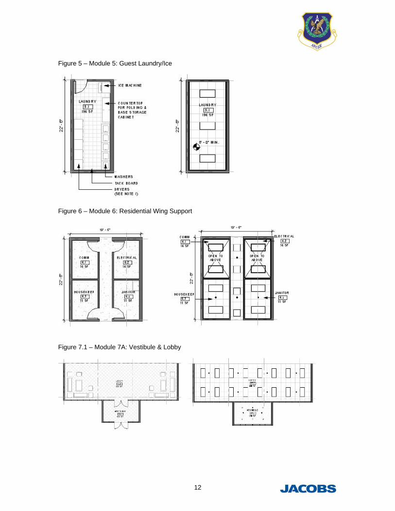
Figure 5 – Module 5: Guest Laundry/Ice
Figure 6 – Module 6: Residential Wing Support
Figure 7.1 – Module 7A: Vestibule & Lobby

13
Figure 7.2 – Module 7B: Reception/ Retail/ Luggage
Figure 7.3 – Module 7C: Business Center
Figure 8 – Module 8: Fitness Room

14
Figure 9 – Module 9: Public Restrooms
Figure 10 – Module 10: Conference Room
Figure 11 – Module 11: Rickenbacker’s

15
Figure 12 – Module 12: Administration

16
Figure 13 – Module 13: Staff Locker Rooms
Figure 14 – Module 14: Staff Break Room

17
Figure 15 – Module 15: Equipment/ Bulk Storage

18
Figure 16 – Module 16: Linen Storage
Figure 17 – Module 17: Janitor Areas
19
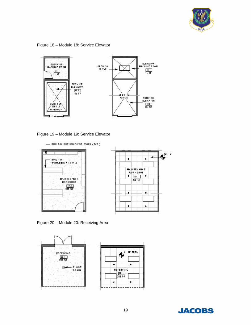
Figure 18 – Module 18: Service Elevator
Figure 19 – Module 19: Service Elevator
Figure 20 – Module 20: Receiving Area

20
Figure 21 – Module 21: Electrical Room
Figure 22 – Module 22: Mechanical Room
Figure 23 – Module 23: Guest Elevator

21
Figure 24 – Module 24: Stairs
Mega Module Illustrations
The following figures show floor plans of mega modules (not to scale). Mega modules are shown
to illustrate one possible way the individual modules can be arranged and are not intended to
constitute a final design.

22
Figure 25 – Mega Module 1: Residential Wing

23
Figure 26 – Adjacency Diagram for Guest Services
Figure 27 – Adjacency Diagram for Administration

24
Figure 28 – Mega Module 2: Guest Services & Administration

25
Figure 29 – Adjacency Diagram for Mega Module 3: Back of House Support

26
Figure 30 – Mega Module 3: Back of House Support

27
Building Illustrations
The following figures show building floor plans (not to scale). Building plans are shown to
illustrate one possible way the individual modules & mega modules can be arranged and are not
intended to constitute a final design.
Figure 31 – Building: 120-Room Visiting Quarters First Floor Key Plan
Figure 32 – Building: 120-Room Visiting Quarters Enlarged First Floor Plan

28
Figure 33 – Building: 120-Room Visiting Quarters Second Floor Key Plan
Figure 34 – Building: 120-Room Visiting Quarters Enlarged Second Floor Plan

29
Figure 35 – Building: 200-Room Visiting Quarters First Floor Key Plan
Figure 36 – Building: 200-Room Visiting Quarters Enlarged First Floor Plan
30
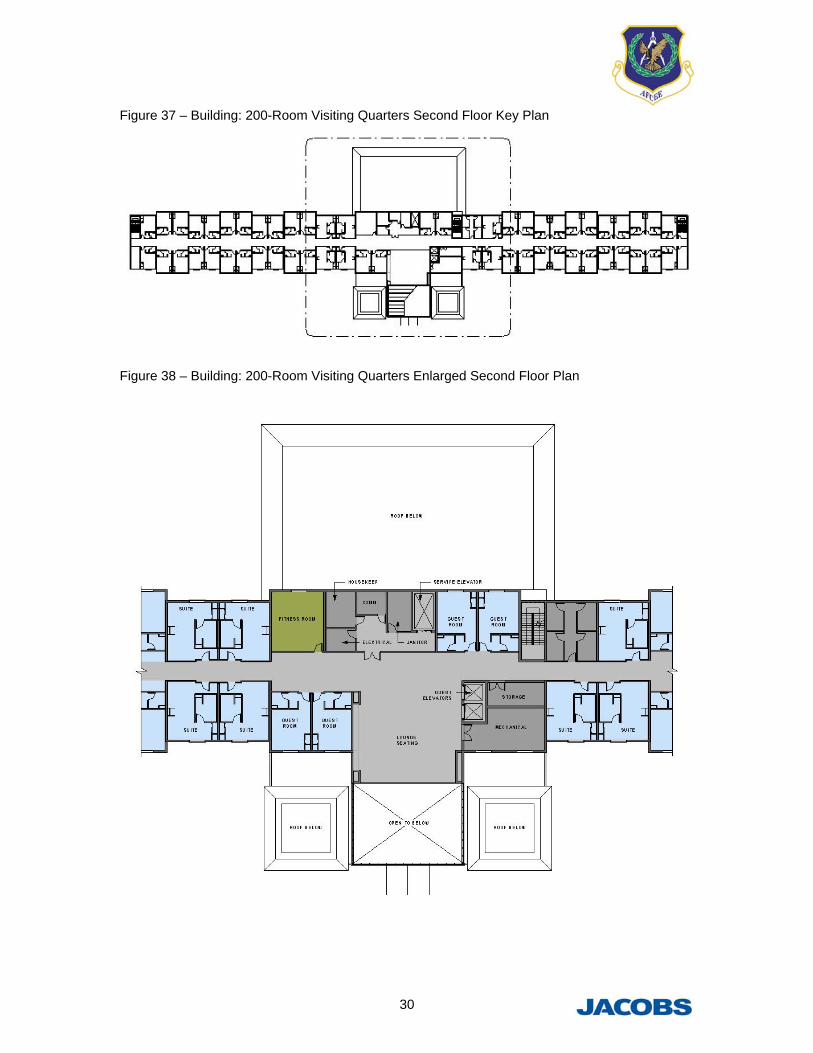
Figure 37 – Building: 200-Room Visiting Quarters Second Floor Key Plan
Figure 38 – Building: 200-Room Visiting Quarters Enlarged Second Floor Plan

31
Figure 39 – Building: 300-Room Visiting Quarters First Floor Key Plan
Figure 40 – Building: 300-Room Visiting Quarters Enlarged First Floor Plan

32
Figure 41 – Building: 300-Room Visiting Quarters Second Floor Key Plan
Figure 42 – Building: 300-Room Visiting Quarters Enlarged Second Floor Plan

33
Figure 43 – Building: 300-Room Visiting Quarters Third and Fourth Floor Key Plan
Figure 44 – Building: 300-Room Visiting Quarters Enlarged Third and Fourth Floor Plan

34
Figure 45 – File Directory Structure Example

35
Figure 46 – Duplication Example
Figure 47 – Group Manipulation Example