dynamic modeling and control of a ball-joint-like variable-...
TRANSCRIPT
Kok-Meng Lee Associate Professor,
The George W. Woodruff Sctiool of IVIectianical Engineering,
Georgia Institute of Tectinoiogy, Atianta, GA 30332-0405
Ronald B. Roth Manager of Engineering,
Ttie HV Tectinoiogies, Inc., Trenton, GA 30752
Zhi Zhou Member of Tecfinical Staff,
AT&T Beil Labs., 2000 Nortfieast Expressway,
Norcross, GA 30071
Dynamic Modeling and Control of a Ball-Joint-Like Variable-Reluctance Spherical Motor Examination of existing joint designs for robot wrist applications has indicated that a spherical wrist motor offers a major performance advantage in trajectory planning and control as compared to the popular three-consecutive-rotational joint wrist. The tradeoff, however, is the complexity of the dynamic modeling and control. This paper presents the dynamic modeling and the control strategy of a three degree-of-freedom (DOFj variable-reluctance (VR) spherical motor which presents some attractive possibilities by combining pitch, roll, and yaw motion in a single joint. The spherical motor dynamics consist of the rotor dynamics and a torque model. The torque model is described as a function of coil excitations and a permeance model in terms of the relative position between the rotor and the stator. Both the forward dynamics which determine the rotor motion as a result of activating the electromagnetic coils and the inverse model which determines the coil excitations required to generate the desired torque are derived in this paper. The solution to the forward dynamics of the spherical motor is unique, but the inverse model has many solutions and therefore an optimization is desired. Experimental results verifying the dynamic model are presented. The control of a VR spherical motor consists of two parts; namely, the control of the rotor dynamics with the actuating torque as system input, and the determination of the optimal electrical inputs for a specified actuating torque. The simulation results and implementation issues in determining the optimal control input vectors are addressed. It is expected that the resulting analysis will serve as a basis for dynamic modeling, motion control development, and design optimization of the VR spherical motor.
1 Introduction An increasing need for high performance robotic applications
has motivated several researchers to direct their investigation efforts to new actuator concepts to improve the dexterity of robotic wrists. Examination of the existing mechanical joints reveals that the ball-joint-like spherical actuator is an attractive alternative to the three-consecutive-rotational joint configuration. The interest in spherical motors as robot wrists is triggered because of their ability to provide roll, yaw, and pitch motion in a single joint, and because they are isotropic in kinematics and kinetics, and they have relatively simple structures. Also, they have no singularity in the middle of workspace except at the boundary. The elimination of gears and linkages enables both high positioning precision and fast dynamic response to be achieved by a properly designed spherical motor. These attractive features have potential applications such as high-speed plasma and laser cutting where the orientation must be achieved rapidly and continuously with isotropic resolution in all directions.
A spherical induction motor was conceptualized by Vachtsev-anos et al. (1987) for robotic applications, and a detailed analysis was given by Devay and Vachtsevanos (1987). However, it is difficult to realize a prototype of its kind because of its complexity in mechanical and winding design and manufacturing, which requires inlaying all three transversing windings on the inner spherical surface of the stator. Laminations are required to prevent movement of unwanted eddy currents. Complicated three phase windings must be mounted in recessed grooves beside the rolling supports for the rotor in a static configuration. These and other considerations have led Lee et
Contributed by the Dynamic Systems and Control Division for publication in the JOURNAL OF DYNAMIC SYSTEMS, MEASUREMENT, AND CONTROL . Manuscript
received by the DSCD August 25, 1993. Associate Technical Editor: C. de Silva.
al. (1988) to investigate an alternative spherical actuator based on the principle of a VR stepper motor that is easier to manufacture. Lee and Kwan (1991) developed the theory based on the local interaction between the adjacent stator and rotor poles to demonstrate the concept feasibility of the spherical stepper motor. To allow a few but evenly spaced stator poles to be used for smooth motion control, Lee and Pei (1991) analyzed the kinematic relationships between the stator and rotor poles which are located at the vertices of regular polyhedrons, and developed a method to examine the influences of the design configurations on motion feasibility.
Hollis et al. (1987) have developed a six DOF direct-current (DC) "magic wrist" as part of a coarse-fine robotic manipulation. An alternative DC spherical motor design with three DOF in rotation was demonstrated by Kaneko et al. (1988). This motor can spin continuously and has a maximum inclination of 15 deg. Although the DC spherical motor is characterized by its constructional simplicity, the range of inclination and the torque constant are rather limited. Foggia et al. (1988) demonstrated an induction type spherical motor of different structure, with the range of motion characterized by a cone of 60 deg. Since the control strategy of the induction motor has not been well developed, no results were given on the ability of the motor to realize any arbitrary motions.
As compared with its DC counterpart, a VR spherical motor has a relatively large range of motion, possesses isotropic properties in motion, and is relatively simple and compact in design. The tradeoff, however, is that a sophisticated control scheme is required. For this reason, we discuss here in detail the dynamic model and the control strategy of a VR spherical motor. The major contributions of this paper are summarized briefly as follows: (1) The paper presents a detailed study of dynamic modeling and control strategy of a three DOF VR spherical motor. (2) An analytical torque model has been derived using
Journal of Dynamic Systems, Measurement, and Control MARCH 1996, Vol. 1 1 8 / 2 9
Copyright © 1996 by ASMEDownloaded 16 Mar 2010 to 130.207.50.192. Redistribution subject to ASME license or copyright; see http://www.asme.org/terms/Terms_Use.cfm

(SX) Retaining Rings
(5X) Bearings
Fig. 1 VR Splierlcal motor prototype
the energy conservation principle governing the electromagnetic interaction of the VR spherical motor. The model describes the relationship between the torque generated by the spherical motor and the input currents applied to the coils. The torque model is shown to depend on the airgap permeance which is a function of the relative position between the adjacent stator poles and rotor poles. (3) An experimental method which allows the air-gap permeance to be determined directly from the spherical motor has been developed. The technique has been used to derive the airgap permeance function from a VR spherical motor prototype using a linear magnetic circuit model. (4) The analytical model has been experimentally validated. The results showed reasonably good agreement between the analytical and experimental data.
The remaining paper is organized as follows: Section 2 describes briefly a general structure of a VR spherical motor, followed by a derivation of the dynamic model. Section 3 proposes the motion control strategy and the real-time implementation issues of the spherical motor. Section 4 describes a specific
stator'
Fig. 2 Exploded assemble view of the prototype
VR spherical motor prototype and the experimental testbed. Section 5 presents a technique to determine the permeance function experimentally. Experimental results and discussions of the torque model are given in Section 6. Finally, conclusions are drawn in Section 7.
N o m e n c l a t u r e
Ai, A2, A3 = matrices in the quadratic torque model
5max = maximum flux density C,„, Q,,j = position vectors of the (th
stator pole and 7th rotor pole
D = a closed, connected, and bounded region in product space of IR* and M, or D C R^ X IR
Eg = input electrical energy E,n = magnetic energy stored in
airgap I^, ly, I^ — moments of inertia about X,
y, and z axes J = objective function in opti
mization K], K2 = gain matrices of control
law M = inertia matrix M = penalty factor
Mji, Myj = magnetomotive forces
(mmf's) generated by the (th stator pole and the y'th rotor pole
P = general permeance function
Pij = permeance, the reciprocal of R,j
Q — intermediate variable R, R ' = transformation matrices
R = mean radius of a spherical surface separating the pole faces of the stator and the rotor
Rr = radius of the rotor Rij = reluctance of the airgap be
tween the r'th stator pole and the jth rotor pole
W" = m dimensional real space T = torque vector, T = [Ti, Tj,
Te = mirror image of the torque T
Ti = torque components in x, y, and z directions
r , , Ty, T^ = computed torque components mx,y, and z directions
V = magnetic potential of the magnetic conductor layer with respect to that at the center of the rotor
Wc = coenergy of the magnetic system
X = state vector XYZ = stator-flxed Cartesian coor
dinate frame e = trajectory tracking error vec
tor, e = q - q^
61, 62, 63 = unit vectors along the x,y,z axes of the rotor body frame
C// = unit vector perpendicular to the position vectors O,,/ and 0,j
f = general nonlinear function vector
m = number of stator poles n = number of rotor poles
Po, PI, . . . , PN = coefficients of permeance function series expansion
q = generaUzed orientation vector
q,i = desired generalized orientation vector
t, to = time and initial time u = electrical input vector,
or the ampere-turns of the electromagnetic coils
= current = control vector = initial state
X = specific trajectory xyz = rotor-fixed Cartesian
coordinate frame a, P, y = coefficients of input
vector superposition ijj, 9, 4> = ZYZ Euler angles
u V
xo = x(ro)
30 / Vol. 118, MARCH 1996 Transactions of the ASME
Downloaded 16 Mar 2010 to 130.207.50.192. Redistribution subject to ASME license or copyright; see http://www.asme.org/terms/Terms_Use.cfm

2 Dynamic Model A prototype VR spherical motor is shown in Fig. 1. The
corresponding assembly view is given in Fig. 2. The spherical motor consists of four subassemblies: the rotor, the stator, the bearing system, and the measuring mechanism. The spherical rotor and the hollow spherical stator are concentric and are supported one on the other by means of gimbals. The poles on the stator, called stator poles, are wound by coils, and each coil can be energized individually. The ferromagnetic poles are strategically distributed on the stator surface. Similarly, the rotor
In terms of Z-Y-Z Euler angles, q = [i//, Q, Y, the rotor dynamic equation is given as follows:
M(q)q + h ( q , q ) = T
where
— ISgC^ ISfC^ LCs
is^ IC^ 0
0 0 /.
(1)
h ( q , q ) =
M(q) =
+ 0<^Q) - (/ - h){4'SeS,^ + 0C^)(4,Q + 4>)
poles are distributed on the rotor surface. The rotor poles meet at the center of the rotor, and the stator cores are connected by the magnetic conductor layer in the stator shell to form a magnetic circuit with the airgap. In order to maintain geometrical symmetry for simplicity in control, the stator poles and the rotor poles are of a circular shape.
The spherical rotor is constrained but allowed to roll on the bearing gimbals which are mounted on the inner surface of the stator. The spherical surface of the rotor, except that of the magnetic poles, is made of non-magnetic but hard material to provide a smooth spherical surface for the bearing rollers to roll on.
The measuring system consists of two circular guides that are made to rotate by the output shaft attached to the rotor. The circular guides are arranged perpendicular to each other such that they can be rotated freely about the x- and y-axes of the stator coordinate frame and measured by means of encoders. The third encoder measures the rotation of the output shaft. The kinematic relationships between the measuring system which consists of two angular guides and three encoders, have been given by Lee and Pel (1991).
The spherical motor is operated on the principle of variable reluctance. In the operation of the VR spherical motor, the stator coils are energized individually using the control circuitry. A magnetic field is established which creates magnetic energy in the airgap. The created energy is a function of the relative position of the rotor and the stator. The motion of the VR spherical motor is thus generated as the rotor tends to move to a position such that the energy stored in the airgap is minimized. Thus, the dynamic model of the spherical motor consists of two parts; namely, the rotor dynamics, and the torque generation.
2.1 Rotor Dynamics. As shown in Figs. 1 and 2, the structure of the spherical motor has certain symmetric properties with respect to Z-Y-Z Euler angles, which will be greatly exploited in solving the optimal control input for a specified torque in Section 3.2. Thus, the orientation of the spherical motor is specified using the Z-F-Z Euler angles. A body coordinate frame of the rotor, xyz, is attached at its center with its z-axis pointing along the rotor shaft. An inertial coordinate frame XYZ is fixed at the center of the stator such that the X and Y axes lie along the two orthogonal bearing pins and with its Z axis pointing toward the opening of the stator.
and where T = [Ti, 72, Ta]^ is the actuating torque vector; / = 4 = 4 and 4 are the moments of inertia about the principle axes; and 5(. > and C(. > denote the trigonometric sine and cosine functions of the angle (• ), respectively.
2.2 Torque Model. The torque generated by the spherical motor is a function of input currents applied to the stator coils and rotor orientation for a given structure. In the following derivation, the electromagnetic interaction between the rotor and the stator poles is modeled as a function of airgap reluctance and the electrical inputs. Next, the torque generation is derived using the principle of conservation of energy. A compact form of the torque model is then presented. Finally, the properties of the torque model are discussed.
2.2.1 Electromagnetic System. In order to obtain some knowledge of the initial design as well as to derive an analytical model of the spherical motor for motion control, a lumped-parameter approach analogous to the linear electric circuit is used in the electromagnetic modehng. The linearized model allows the flux flowing through the reluctance of airgaps to be considered separately. The following assumptions are made in the derivation of the analytical model: (1) The reluctance of the iron core is negligible as compared to that of the airgap and thus the energy storage occurs solely in the air gap. The error introduced by this assumption depends on the geometrical dimensions of the structure and the permeability of the material. This error, in general, can be significantly reduced with magnetic materials of high permeability and low excitation levels. (2) Leakage flux is assumed to be negligible. This constraint is enforced by maintaining a large distance in comparison to the airgap between adjacent rotor poles, adjacent stator poles, and the bottom of the stator pole tooth to inside stator.
For the purpose of modeling the VR spherical motor, the motor is considered to consist of three major components as shown in Fig. 3, namely a set of m interconnecting stator poles, a set of n interconnecting rotor poles, and the air gaps formed between pairs of overlapped stator and rotor poles. The model permits a variety of magnetic field interactions to be investigated. In Fig. 3, Msi and M^j denote the magnetomotive forces (mmf 's) generated by the i'th stator pole and the j'th rotor pole, respectively, Rjj denotes the reluctance of the airgap between the j'th stator pole and the jth rotor pole, and ^.j is the corre-
N o m e n c l a t u r e ( c o n t . )
ipij = angle between the position vector ^ j , 2, 3 = intermediate variables of the j'th stator pole and theyth /Uo = permeability of air rotor pole
77, ^ = tilt angles from nominal position X = chi squared statistic quantity (a = angular velocity of the rotor
*,j = magnetic flux flowing through Ry ^rj - magnetic flux flowing through the
(th stator pole *s; = magnetic flux flowing through the
yth stator pole
Journal of Dynamic Systems, Measurement, and Control MARCH 1996, Vol. 1 1 8 / 3 1
Downloaded 16 Mar 2010 to 130.207.50.192. Redistribution subject to ASME license or copyright; see http://www.asme.org/terms/Terms_Use.cfm

r Fig. 3 Magnetic circuit
sponding flux flowing through Rij. The magnetic potential of the magnetic conductor layer at the stator shell with respect to that at the center of the rotor is denoted as V.
The magnetic flux #y can be determined with the aid of Fig. 3 as
%j = Pii[M,i + M,j - V], (2)
where the permeance Py is the reciprocal of Ry. Since m n
I I $« = 0, (3) 1=1 7 = 1
the magnetic potential V can be derived by substituting $y from Eq. (2) into Eq. (3) , which leads to
i=l j = l /=1 J = l
(4)
For a specific spherical motor structure, the airgap permeance Pij is a function of the angle between the position vectors of the jth stator pole and theyth rotor pole, (^,j, namely.
Pii = PWij)- (5)
Equation (5) is referred here as a permeance model. Both numerical computation (Pei, 1990) and experimental
results (Lee and Kwan, 1991) have indicated that a typical permeance model P{tp) has the following properties: (1) P(y?) is even, positive, and monotonically decreasing to zero as the displacement increases. (2) The derivative of P(ifi) has a local maximum or minimum at ^p = ±y>„, where ip„ is a constant for a given geometry. (3) The value of P((p) about the vicinity of the origin and at the origin (i.e., when the poles are fully overlapped) can be reasonably well-determined by
P(<P) tJ'oSjip)
(6)
where Ho is the permeability of air; g is the shortest path length between two parallel pole-faces; and S(ip) is the overlapping area between the stator pole and the rotor pole. In addition, the following condition must be satisfied in modeling the permeance function for a spherical motor: Pi(p) must be periodic with period Iw. Thus, using Fourier series expansion on [ - TT, TT] and retaining the first A terms, the following periodic permeance function can be obtained.
Pif) = Po + 'L Pk cos (kip) (7)
where the coefficients {po, Pu • • •, PN] can be computed from experimental data. Note that Pif) is an even function and therefore the sine terms vanished.
2.2.2 Governing Equations of Energy Conversion and Torque Generation. The torque generated by the electromagnetic system is governed by the principle of conservation of energy, which states that
E,{t) - E„(t) = T ( 0 • (o(t) (8)
where E^ is the time rate of magnetic energy stored; E^ is the electrical power input; cj is the angular velocity of the rotor. The mechanical powers can be rewritten as
T • w = X Tk4>k (9)
where the time derivatives of < j. are the angular velocities measured with respect to the rotor body frame. Using the results from Eqs. (8) and (9), and noting that the differentials of 4>k are independent of each other, the torque generated by the magnetic system is given by
V ( £ , - EJ, (10)
where
d Ci + 62 +
d4>. 6 3
and Ctik = 1, 2, 3) is the unit vector along the x,y, z axes of the rotor body frame, respectively. The electrical power input to the system and the total magnetic energy stored in the system are given by
i=i j = i
1 .^ " $?.
^ 1=1 j = i ^U
(11)
(12)
From Eqs. (11), (12), and (4), the output torque can be obtained from Eq. (10) as
m fi
T = 5 I I (M,,. + M,,. - y)^VPy, (13) ; . i j = i
A detailed derivation ofEqs . ( l l ) , (12) ,and(13)canbefound in (Lee, 1992a).
The permeance P,j is a function of the angle and distance between the ith stator pole andyth rotor pole, as shown in Eq. (5). The angle, ipij, can be determined from the dot product of the position vectors of the ith stator pole andyth rotor poles as follows:
cos (ifij) = c • r
where R is the radius of a spherical surface separating the pole faces of the stator and rotor; and C„ and C^j are the position vectors of the stator and rotor poles, respectively. From Eq. (13), it can be shown by using differential geometry that the torque is given by
T = ^ I I i = l J=l
(M„. -I- Mrj - V) 2dPW) dip
(14)
where tg is the unit vector perpendicular to the position vectors Cj, and Crj, which can be determined from the following equation:
R^ sin {ifij) (15)
Thus, Eqs. (4) , (14), (15), and a permeance model define the
32 / Vol. 118, MARCH 1996 Transactions of the ASME
Downloaded 16 Mar 2010 to 130.207.50.192. Redistribution subject to ASME license or copyright; see http://www.asme.org/terms/Terms_Use.cfm
torque generated by the spherical motor for a given set of inputs in terms of the magnetomotive forces of the coils.
2.23 Torque Model in Quadratic Form. In practice, it is preferable that there be no wiring in the moving parts or in other words, only simple iron cores with no excitation coils are used as rotor poles (i.e., Mrj = 0, 7 = 1, . . . , n) . With this assumption, we consider here the case where only current sources are used in the stator coils and the mmf's of the coil are treated as system input variables. The torque model given by Eq. (14) can be written in matrix form as follows:
T, = i u'^A.u, 1, 2, 3 (16)
where
A. = I ( i ^ ( >
u = [M,i ...M,,nV^ K'",
(e,;-e,) )(a - c,)(a - c,)'',
c, = [0, 0, . . . , 0 , 1,0, . . . , 0 ] ' ' , /th
a = [ai, 02, • • • > Oil • • •, amV^ n m n m
a, = S Piili.lL I P>i) and I a, = 1 j=\ i=\ ]=\ 1=1
classical linear control approaches can then be applied to each of the coordinates separately. As an example, the control vector V may be chosen as
V = q^ - K i ( q - (jrf) - K2(q - q,,)
where
K, = diag [A:,^, iiTie, ATi ] and K2 = diag [/Tj*,/fao,/^a^]-
The tracking error e = q - q is guaranteed to approach to zero asymptotically if the elements in Ki and K2 are all positive.
The inertia matrix M(q ) given in Eq. (1) is not invertible at S = 0, which is, in fact, a singular point for the rotor dynamics in Z-Y-Z Euler angles. At the singular point, Eq. (18) can not be obtained from Eqs. (1) and (17). We shall examine the validity of the control law at the singular point. The Euler equations are rewritten in state-space representation:
* = f(x, T ) , (19)
where f is known as the vector field in differential equation theory (Hale, 1980). As # * 0, we have \ = [ip, 0, (f), i/», 0, iV, and
[Ifi(>lfQ + </.)
"A 0
21041Q T,C,^ + T2S^]/IS,
IfiC^i^Ce + <!.)]/(/« -I- ( r , Q - T2S^}Q/(ISs) + T,/l,
(20)
and where the matrix Ai varies with the orientation of the rotor. The torque model of a current-controlled spherical VR motor
given by Eq. (16) is algebraic and quadratic with respect to u or the ampere-turns of the electromagnetic coils. The torque model yields a unique torque vector for a specified set of coil excitations. However, there are generally infinite sets of coil excitations to produce three desired torque components.
3 Motion Control Strategy The motion control of the VR spherical motor consists of
two parts. The first part is to determine the actuating torque of the VR spherical motor so that the motor follows a desired trajectory. The second part determines the optimal electrical inputs to generate the required actuating torque determined from the first part by using the control law for tracking the desired trajectory.
3.1 Control of Rotor Dynamics. The control task here is to determine the actuating torque so that q would track the desired trajectory q^. The spherical motor is controlled by using the computed torque method (Spong and Vidysagar, 1989), where the control law is chosen in the form
T = M(q)v + h ( q , q ) (17)
and where v = [i;^, Ua, v^]'^ is the control vector. Using the control law defined in Eq. (17), the closed-loop dynamic equation becomes Mij = Mv. Since | M | = 0 for V^ =!t 0, therefore, we have
q = V. (18)
Equation (18) represents a linear system with three decoupled second-order subsystems under the control vector v, and hence
As ^ = 0, Eq. (1) becomes
(21)
In state-space representation, as ^ = 0, we have x = [6, 1// + (f), 0, ijj, + (/)]''and
f(x, T ) = ij, + <l>
TJL
(22)
If the actuating torque T is determined by Eq. (17), then the right-hand side of Eq. (19) is continuous on D C IR** X R, a closed, connected, and bounded region. Furthermore, it also satisfies a local Lipschitz condition on D. Then for any (xo, to) e D, where XQ = x(?o), ?o is the initial time, there exists a unique solution x ( ' , Xo, to) defined over some interval a <i to < b with (Xo, [a, b]) C D. Moreover, the solution depends continuously on to and XQ. This argument is based on the Pi-card's Existence and Uniqueness Theorem (Hale, 1980).
The mapping field f in Eq. (19) is not continuous at 0 = 0 and hence, local Lipschitz condition is not satisfied. In fact, the rotor motion can essentially be described by two independent variables 9 and I/J + </» at ^ = 0 where the precession and the spin axes are aligned and measured about the same axis. The vector field f degenerates from IR* in Eq. (20) to H" in Eq. (22). Thus, many solutions exist around the singular point of the Z-Y-Z Euler angles, as there are two independent equations with three Euler angles.
By the physical nature of the ball-joint-like spherical motor, the solution to Eq. (1) should be continuous. To ensure a smooth
Journal of Dynamic Systems, Measurement, and Control MARCH 1996, Vol. 1 1 8 / 3 3
Downloaded 16 Mar 2010 to 130.207.50.192. Redistribution subject to ASME license or copyright; see http://www.asme.org/terms/Terms_Use.cfm

0.5 1 1.5
Time in seconds
0.5 1 1.5
Time in iKondt
Fig. 4 Simulation results of computed torque method
motion at ^ = 0, a generalized vector field must be constructed at ^ = 0 such that the vector field of the closed-loop system is continuous for the rotor dynamics given by Eqs. (20) and (22). Since the possession and spin angles at ^ = 0 can be arbitrarily chosen provided that their sum is uniquely determined by the location of the body, the vector field v in Eq. (18) can be treated as a generalized vector field for the control law defined by Eq. (17). With Eq. (22) replaced by Eq. (18) at 6 = 0, the vector field is continuous over the whole range of motion and satisfies Lipschitz conditions and hence, the unique solution is ensured. Typical simulation results for a rotor of 75 mm diameter with design / = 8.0538J5-4 Kg-m' and /, = 5.3775£-4 Kg-m' are shown in Fig. 4.
3.2 Control Input Optimization. The control input optimization is essentially an inverse problem to the torque model. The solution to the inverse problem is to compute a set of coil excitations, which is denoted here as a control input vector u, that is required to generate the desired torque T. Given the desired torque, u may be determined from Eq. (16) by solving the algebraic equations. However, since u G R" where m is the number of stator coils, a sufficiently larger integer as compared to the degrees of freedom of the spherical motor, there are generally an infinite number of solutions to the inverse problem.
3.2.1 Optimization Algorithm. The generalized reduced gradient (GRG) method (Wolfe, 1967 and Abadie, 1969) is used to solve for the optimal input vector u, which would minimize the following functional:
•/(u) = I 1
\Ui\ + M X - uXu - T, (23)
where Af > 0 is a very large real number. The first term in the functional is to minimize the current amplitude or the consumed electrical power, and the second term is an addition of a penalty term taking into account the system constraints represented by Eq. (16). Typical values of p are 1 and 2. When p is chosen as 1, the sum of the current amplitudes is minimized. If the consumed electrical power of the spherical motor is to be minimized, p is set to 2.
It has been shown that the torque model is nonlinear, and the inverse problem is characterized by its multiple solutions. Although it has been numerically found that the GRG method works well in minimizing the functional represented by Eq. (23), the average time to compute an optimal input vector using off-the-shelf GRG optimization software is in the order of minutes on an Intel 80386 33 MHz personal computer. For real-time control applications where the computation time is in the order of milliseconds, a practical technique for computing a smooth solution to the inverse problem is necessary. The implementation technique introduced here consists of a practical
look-up table which can be precompiled off-line, and a realtime interpolation algorithm. The objective is to determine the minimum set of control vectors off-line, then store them in a look-up table for on-line use.
3.2.2 Practical Look-Up Table of the Inverse Torque Model. The look-up table should allow an optimal input vector to be determined for a required torque at any given rotor orientation. If each of the six parameters (three torque components and three Euler angles) is characterized by L points over its operating range and two bytes are used to represent each of the m control inputs and the six parameters, the memory size required by the look-up table will be 2 mL' . For a system with 11 independently controlled inputs, the required memory size is over 1300 MBytes even if only 20 points are used to characterize each of the parameters. Two approaches, parameter elimination and the use of symmetry, are discussed in the following to reduce the table size required for practical implementation.
Table Size Reduction by Parameter Elimination. This approach is to eliminate the three torque parameters by introducing three control input vectors Ui, U2, and U3 such that these control vectors would generate the unit torques about the three independent rotor axes, respectively. For a specified torque at any arbitrary direction, the input vector u is then computed fromEq. (24).
u = aUi -I- /?U2 -I- 7U3 (24)
where a, P, and y are coefficients to be determined for a specified torque. By substituting Eq. (24) into Eq. (16), we have
\[a,l3,y]^Xa,p,yY=T, (25)
where
ufA.Ui u[AiU2 u[A,u3 ujAjU] U2A1U2 U2A,U3 u^AjUi \xlA.,\X2 Us AjUs
and t = 1, 2, 3. The coefficients a, /3, y are solved from Eq. (25), and thus the required control input vector u can be obtained by superposition using Eq. (24). By storing the three input vectors Ui, U2, and Uj for a given orientation in the precompiled table, the torque variables are eliminated and the memory size required in the look-up table is reduced to 6 mL' bytes.
Table Size Reduction By Use of Symmetry. Since the torque parameters are eliminated from the table, the control inputs are tabulated in terms of the rotor orientation only. The operating Z-Y-Z Euler angles are 0 •& ij/ s ITT, - Tr/4 ^ 0 7r/4, and 0 ^ cf) r^ 2ir, where ijj, 9, and (p are the precession, nutation, and spin angles respectively. If the resolution of the parameters is r points/radian, the memory size of 12 m (TTT)' bytes would be required. Further reduction of the look-up table can be achieved by using the symmetry of the pole locations to reduce the range of orientation parameters. A scheme was devised to illustrate the principle using a particular configuration where the stator and the rotor poles are arranged at the vertices of an icosahedron and an octahedron respectively. It is expected that similar arguments can be readily extended to other configurations where poles are arranged in the pattern of regular polygons. The following examples illustrate the basic principle.
Symmetry of Rotor Poles. Consider the spherical rotor which has five evenly spaced poles arranged at the apices of an octahedron. The topmost pole (#6) is eliminated to provide
34 / Vol. 118, MARCH 1996 Transactions of the ASME
Downloaded 16 Mar 2010 to 130.207.50.192. Redistribution subject to ASME license or copyright; see http://www.asme.org/terms/Terms_Use.cfm
-*T- i *i > -r*T—y ,, 1
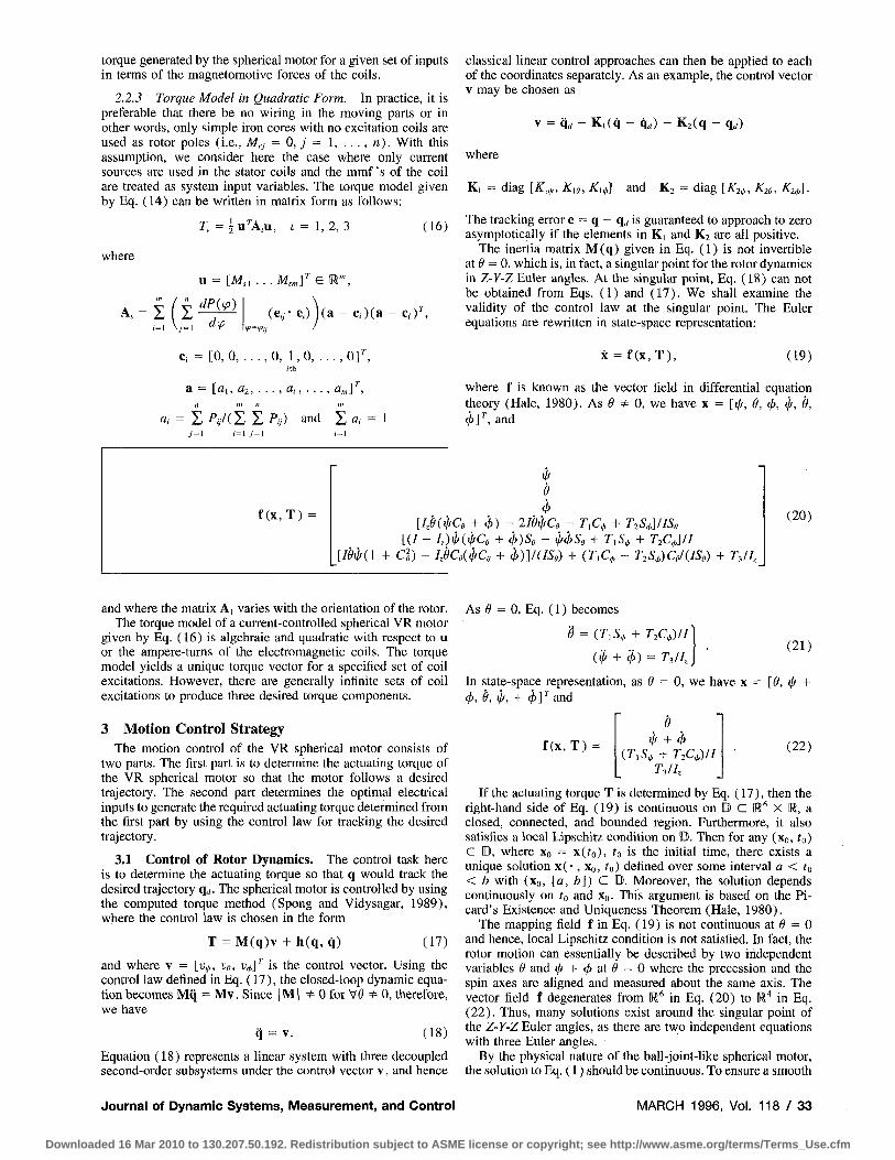
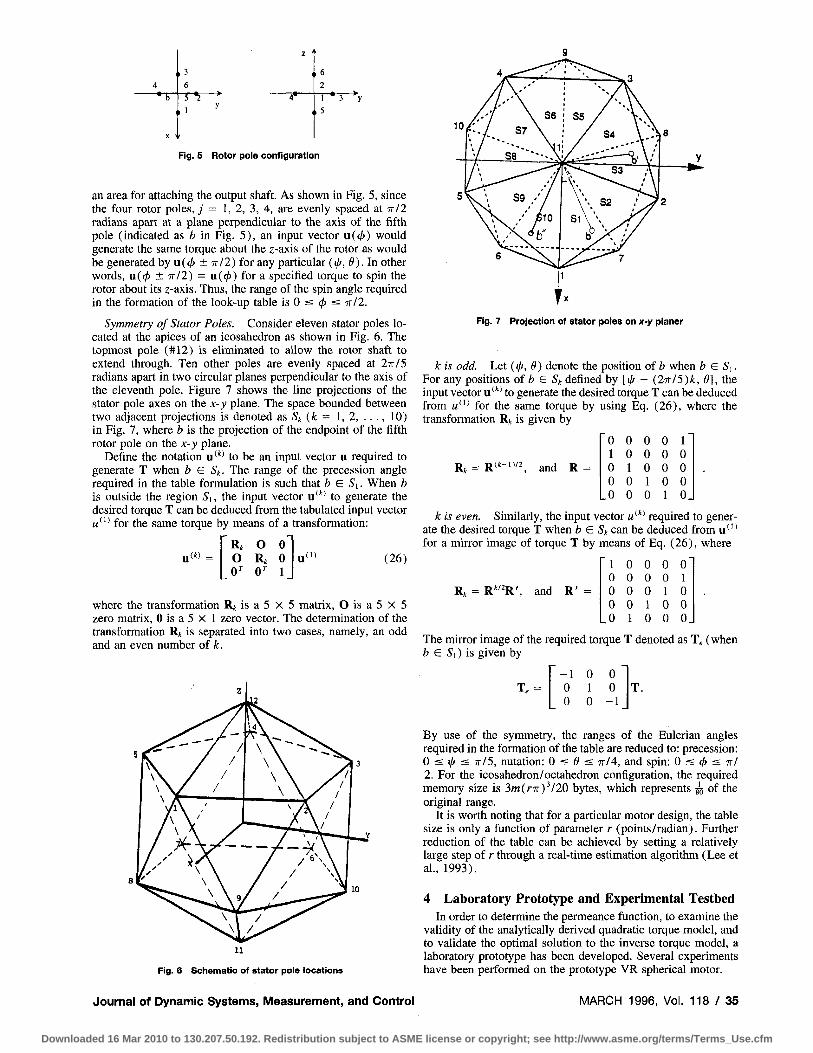
Fig. 5 Rotor pole configuration
an area for attaching the output shaft. As shown in Fig. 5, since the four rotor poles, j = 1, 2, 3, 4, are evenly spaced at n/l radians apart at a plane perpendicular to the axis of the fifth pole (indicated as b in Fig. 5) , an input vector u(</>) would generate the same torque about the z-axis of the rotor as would be generated by u((^ ± 7r/2) for any particular (ip, 9). In other words, u((/) ± 7r/2) = u(</))fora specified torque to spin the rotor about its z-axis. Thus, the range of the spin angle required in the formation of the look-up table is 0 < i s ixll.
Symmetry of Stator Poles. Consider eleven stator poles located at the apices of an icosahedron as shown in Fig. 6, The topmost pole (#12) is eliminated to allow the rotor shaft to extend through. Ten other poles are evenly spaced at 27r/5 radians apart in two circular planes perpendicular to the axis of the eleventh pole. Figure 7 shows the line projections of the stator pole axes on the x-y plane. The space bounded between two adjacent projections is denoted as 5^ (fc = 1 , 2 , . . . , 10) in Fig. 7, where b is the projection of the endpoint of the fifth rotor pole on the x-y plane.
Define the notation u"* to be an input vector u required to generate T when b G S^. The range of the precession angle required in the table formulation is such that b G Si. When b is outside the region Si, the input vector u**' to generate the desired torque T can be deduced from the tabulated input vector «*" for the same torque by means of a transformation:
,(*) _ R, O 0 O Rj 0 0^ O' 1
, ( 1 ) (26)
where the transformation Rj: is a 5 X 5 matrix, O is a 5 X 5 zero matrix, 0 is a 5 X 1 zero vector. The determination of the transformation Rj is separated into two cases, namely, an odd and an even number of k.
10
5
y S8 ""'-•-
C \ S9 -''/
S6 I S5
510
K>.,
S4 \.:Y - ' ' ' \ **
• ^ S 3 A'
S2 ! ^ 2
Fig. 7 Projection of stator poles on x-y planer
k is odd. Let (ij/, 6) denote the position of b when b E Si. For any positions of fc e 5* defined by [i/f -I- (2irl5)k, 6], the input vector u**' to generate the desired torque T can be deduced from «*" for the same torque by using Eq. (26), where the transformation R^ is given by
~o 0 0 0 r 1 0 0 0 0 0 1 0 0 0 0 0 1 0 0
, 0 0 0 1 0 .
jj^ ^ jj(t-i)/2^ and R
k is even. Similarly, the input vector M**' required to generate the desired torque T when b G St can be deduced from u''* for a mirror image of torque T by means of Eq. (26), where
R. R*''R', and R'
1 0 0 0 0 0 0 0 0 1 0 0 0 1 0 0 0 1 0 0
, 0 1 0 0 0 .
Fig. 6 Schematic of stator pole locations
The mirror image of the required torque T denoted as T^ (when b € Si) is given by
• " - 1 0 0 0 1 0 0 0 - 1
By use of the symmetry, the ranges of the Eulerian angles required in the formation of the table are reduced to: precession: 0 < !/( :s 7r/5, nutation: 0 < ^ < 7r/4, and spin: 0 < < s TT/ 2. For the icosahedron/octahedron configuration, the required memory size is 3m(r7r)'/20 bytes, which represents ^ of the original range.
It is worth noting that for a particular motor design, the table size is only a function of parameter r (points/radian). Further reduction of the table can be achieved by setting a relatively large step of r through a real-time estimation algorithm (Lee et al, 1993).
4 Laboratory Prototype and Experimental Testbed In order to determine the permeance function, to examine the
validity of the analytically derived quadratic torque model, and to validate the optimal solution to the inverse torque model, a laboratory prototype has been developed. Several experiments have been performed on the prototype VR spherical motor.
Journal of Dynamic Systems, Measurement, and Control MARCH 1996, Vol. 1 1 8 / 3 5
Downloaded 16 Mar 2010 to 130.207.50.192. Redistribution subject to ASME license or copyright; see http://www.asme.org/terms/Terms_Use.cfm

Fig. 8 Experimental setup
The prototype used here is based on a design configuration where the stator and the rotor poles are arranged at the vertices of an icosahedron and an octahedron respectively. The stator of the prototype VR spherical motor is constructed of iron. The stator poles are arranged on the inside of the stator surface following the pattern of a regular icosahedron. The topmost stator pole has been ehminated allowing the motor's output shaft to extend out. The stator poles are installed externally allowing for easy adjustment of the air gap with close-toleranced shim stock. A coil is wound on each stator pole using 26 AWG around copper wire with a heavy layer of Imideze insulation.
The rotor is a round and smooth sphere with iron poles located at the vertices of a regular octahedron. The topmost rotor pole was eliminated to provide an area for attaching the output shaft. The rotor's output shaft can spin continuously and has a maximum inclination of 45 degrees, which is Umited by the opening of the stator and the output shaft diameter. The rotor poles connect at the rotor core providing a complete magnetic flux path. The rotor diameter has been designed to fit through the stator opening allowing for a one piece stator design. Ten transfer bearings, which are threaded externally to the stator, provide redundant support of the rotor while allowing the desired three rotational degrees of freedom. A transfer bearing utilizes a nylon ball and Stainless Steel 300 outer shell both having a low magnetic permeability. Since the airgap permeance function is to be derived from torque measurements, friction would have an adverse affect on the results. In the prototype, the majority of the friction is due to loading of the transfer bearings used to support the rotor. Friction was minimized in the experimental setup by: (1) use of oversized transfer bearings thereby minimizing contact (Hertzian) stresses, (2) small preloading of transfer bearings, and (3) bearing loading due to forces generated by the attraction of adjacent rotor and stator poles minimized due to experiment's symrtietry. For clarity, the assembly process of the laboratory prototype has been documented separately in the form of a video tape (Lee, 1992b).
The locations of the five rotor poles and the eleven stator poles are given in (Roth, 1993). The characteristic dimensions of the VR spherical motor used in the experiments are summarized as follows: The mean radius of the spherical surface separating the stator and the rotor pole faces is 38.1 mm. The radii of the stator and the rotor poles are 12.7 mm and 19.05 mm respectively. The airgap separating the stator and the rotor pole faces is adjusted to 0.75 mm. Both the stator and rotor poles were made of 1018 carbon steel which has a maximum flux density of S ax = 2.1 Wb/m^
An experimental testbed was developed consisting of the VR spherical motor prototype, current amplifiers, force/torque (F/ T) sensor, and an IBM-compatible 80386 PC. This experimental setup was constructed to serve as a platform for verifying the torque prediction model and for developing and implementing feedback control algorithms. The experimental setup is photographed and is shown in Fig. 8. Two DDA-06 expansion Ijoards have been installed in the PC, each of which provides six 12-bit D/A outputs and 24 lines of digital input/output. Eleven of the D/A outputs were connected to eleven high-speed, low
36 / Vol. 118, MARCH 1996
output impedance current amplifiers. Each amplifier was connected to one stator coil. The amplifiers used are Aerotech DS8020 PWM amplifiers. Each amplifier provides a maximum current of 3.25 Amperes. The F/T sensor, manufactured by ATI Corporation, measures the forces and torques. This experimental setup allows the motor's output torque to be measured at all positions in the workspace for purposes of verifying the torque model.
5 Determination of Permeance Function As shown in Eq. (16), the torque model depends on the
permeance function and its derivative of the electromagnetic system. A method to determine the airgap permeance of the spherical motor experimentally is presented in this section. With this method, the static torque output of the spherical motor is measured at a series of positions as a function of current input. Using the analytical torque model, the data is reduced to the airgap permeance.
5.1 Experiment Setup. An F/T sensor is used to determine the motor's output torques by measuring the forces and torques about the three Cartesian axes at the F/T sensor's center. Analysis showed that the torque measurement and computation in z-direction have the minimum uncertainty (Roth, 1993). Therefore, the method for deriving the experimental permeance function used only T^ measurements. For the permeance function experimental setup, the spherical motor prototype was assembled with only two stator poles, Nos. 1 and 6. The coils were connected such that the magnetic flux flows along a closed path, from one stator pole and returns to the other through the rotor poles, as shown in Fig. 9. The rotor is tilted at angle 77 = ^ from the nominal position, At this initial position, rotor pole No. 1 is in perfect alignment with stator pole No. 1, while rotor pole No. 3 is in perfect alignment with stator pole No. 6. Rotor poles No. 2 and No. 4 are 90 degrees from stator poles Nos. 1 and 6. This experimental setup will result in motor output torque about the z-axis only with the lowest uncertainty. The resulting torque measurements are used to determine the experimental airgap permeance.
A series of measurements are made with the input variables being the rotor's rotation about the z-axis and the stator pole's mmf input. The displacement variable is measured by using the prototype's 9^ encoder. The mmf input is controlled using current amplifiers. The output variable is the motor's output torque which will only be about the z-axis due to the use of stator poles Nos. 1 and 6. The motor's output torque is measured by connecting the output shaft of the rotor to the F/T sensor. Bearing loads due to the attractive forces generated between adjacent poles will be theoretically zero due to the symmetry of this experiment at all positions for equal mmf excitation. To
F/T Sensor
Fig. 9 Schematic of the experimental setup
Transactions of the ASME
Downloaded 16 Mar 2010 to 130.207.50.192. Redistribution subject to ASME license or copyright; see http://www.asme.org/terms/Terms_Use.cfm

P.i * i J IR, pJ 3 J \
•=r Ui * 2 ) - ^
P«
- • ^ U6
Fig. 10 Equivalent magnetic circuit representation
ensure a complete magnetic circuit, the input currents to stator poles No. 1 and No. 6 were of equal but opposite polarity.
An equivalent electrical analogy is illustrated in Fig. 10. The relative displacement between the ith stator pole and they'th rotor pole is designated by ipy. To simplify the number of circuit branches, the constraint 0 < (/Jn ^ 7r/2 has been enforced and P(ip > 7r/2) = 0 assumed. By rotating the rotor about the output shaft, the system has only one degree of freedom. For a given displacement between rotor pole No. 1 and stator pole No. l,<pu, the remaining pole displacements can be determined as
Vea = V'li + <5, <Pu = ¥'11 + <5, and ( 53 = Vn- (27)
The constant, 5, is defined as the difference between the angular spacing between adjacent stator poles, p^, and the angular distance between adjacent rotor poles, Pr- For this experimental setup, Ps = TT radians andp^ = 7r/2 radians leading to a simplified torque expression.
By utilizing the equivalent electrical circuit shown in Fig. 10, three mesh equations may be written using Kirchoff 's Voltage Law,
1 1 -I- —
J_ > u
0
1
J_ J. Pu ^ P, 62
P62
0
_ J_
J_ J_ ^ 6 2 ^ 6 3
c. C2 C3
_ 0
Ml — Me
0
The three unknowns C,, (i = 1, 2, 3) are determined by solving the above matrix equation using Eq. (27). The results are obtained as follows:
C : = | / ' ( ^ - f 5 ) ,
C2 = I [/'(¥') + 'P(V + «)]- and 3 = f/'(¥') (28)
where Q = Ui - u^ and tp = (pu- The coenergy of the motor is found by summing all the energy in the four airgaps since iron losses have been neglected,
1^? ^ - 2 . . 2 Pu 2 P62
C3)' , 1 Q 2 Pa
(29)
Substituting the results from Eqs. (27) and (28) into Eq. (29), the coenergy of the system simplifies,
W, = \Q\P{^) + P{^ + 6)].
The motor output torque is found by differentiating the coenergy with respect to the displacement variable, (p. The resulting torque expression, given in Eq. (30), is in terms of the total mmf input, the first derivative of the permeance function, and the difference in pole spacing.
4 dP{^p) dPi^p + 5)
dtp dip (30)
A modified form of Eq. (30) is used to solve for the airgap permeance function.
y, 4 r ( y , ) _ dP(ip)
e ' dip
dPjip + 6)
dip (31)
The left-hand side of Eq. (31), Y,, represents the known relationship between the measured torque and input magnetomotive force at the ipi position. The right-hand side of Eq. (31) represents the unknown model of the airgap permeance derivative function. Since it is not possible to solve in close form for the airgap permeance function from Eq. (31), we instead solve for the permeance function coefficients numerically. The airgap permeance function is expressed in series form using only even basis functions satisfying part of permeance property criteria.
P(vi) = Po + "L pjfV (32) y = i
The right-hand side of Eq. (31) is expanded by substituting the derivative of Eq. (32). The result is Eq. (33) which predicts the unknown relation between independent and dependent variables as
y('P^,Pj) = I 2jpjipV-' + I 2jpjiip^ + 6) 2J'l (33) j = i j = i
A Gaussian distribution model is used to represent the errors associated with the experimental torque measurements. The maximum likelihood estimate (MLE) of the A' unknown coefficients, {pi, P2, pi, •. ., PN] As found by minimizing the quantity, x^, over the M' measured data points (N < M') with individual uncertainties, cr,,
X^ = I j= i
Yi - yWi\Pu •••,PN) (34)
The remaining unknown coefficient, po, is determined by computing the permeance between two perfectly overlapping spherical areas using Eq. (6). The overlapping area is determined by Eq. (35) which integrates the partial surface area of a sphere,
S{ip = 0 ) = 2 7 r / ? r ( l - c o s <^mi„) (35)
where i min in degrees is the minimum size of the two poles and Rr is the radius of the rotor {Rr >> g). For the prototype, ip^ = 28 degrees and tps = 16 degrees, therefore, ip^ir, = min (ip,, tps] = 16 degrees.
The unknown coefficients were determined by utiUzing the generalized reduced gradient (GRG) solver which minimizes a general nonlinear objective function with nonlinear constraints. In this example, the GRG solver minimized the objective function given in Eq. (34) with the constraints given by the restrictions on the airgap permeance function, P(ipi) a P((/7,+ |), PiiPi) > 0, and P(ipi) = P(-iPi), where ( = 1, 2, . . . , M' -1. The third restriction requiring an even permeance function was satisfied by using only even basis functions for the series expansion as used in Eq. (32).
Journal of Dynamic Systems, Measurement, and Control MARCH 1996, Vol. 1 1 8 / 3 7
Downloaded 16 Mar 2010 to 130.207.50.192. Redistribution subject to ASME license or copyright; see http://www.asme.org/terms/Terms_Use.cfm

Displacement (Radians)
- • — 0.25 amps
•°— 0.505 amps
- * — 0.76 amps
^— 1.03 amps
- * — 1,28 amps
•' f— 1.54 amps
• — 1.81 amps
•<^— 2.06 amps
-X— 2.59 amps
' experimental
* overlapping method
0.4 0.6 0.8 1
Displacement (Radians)
1.4
Fig. 11 Experimental torque measurements Fig. 13 Derived experimental airgap permeance
0.15 T
0.1
f7 0.05
i • £, -o.os
-0.1
A ^y\ -W \
0,5 1 , J ^ 2
1 ^ w .0.15 ^
—•=>— 0.505 amps
^ 0.76 amps
—^^— 1.03 amps
— • — 1.28 amps
— ° — 1.54 amps
— • — 1,81 amps
Displacement (Radians)
Fig. 12 T o r q u e c o n s t a n t c o n iparlson
5.2 Experimental Results. The experimental data taken from the prototype is shown in Fig. 11. The relative displacement between stator pole No. 1 and rotor pole No. 1, tpu, was varied from 0 to 90 degrees in approximately one degree increments. The spherical motor's output torque was measured at each position for currents varying from 0.25 amps to 3.11 amps. To distinguish airgap permeance from iron permeance, it was necessary to determine at which measurement level iron losses in the prototype become significant. For the experimental setup and assuming no iron losses, the output torque is proportional to current squared. An expression for the torque constant as a function of relative displacement, A'((^), is derived for the experimental setup as a ratio of the torque about z-axis to the square of the input current
K{^) = r(^)/M^ (36)
The computed torque constant is shown in Fig. 12 by applying Eq. (36) to the experimental torque measurements. The graphs for torque constant are approximately constant for the excitation levels of 0.505 amp and 0.76 amp. Current levels greater than 0.76 amp show a decreasing torque constant illustrating that iron losses are becoming significant. The 0.76 amp data was used to derive the airgap permeance function since it has a smaller measurement uncertainty than the 0.505 amp data.
The derived permeance coefficients are given in Table 1. The results for the experimental airgap permeance function and theoretical overlapping area permeance are given in Fig. 13. The two airgap permeance functions show good correlation for small pole separations. This result is expected as fringing flux, which is neglected in the overlapping area model, is minimal
Table 1 Airgap permeance coefficients (even bases function expansions)
Pa = Pi = P4 = P6 =
6.155327E-07 -3.729770E-06 -3.927777E-06
8.438715E-08
p, = 6.536474E-08 /)3 = 6.147109E-06 p, = 7.780053E-07 /), = 5.366798E-08
for small displacements. The experimental results diverges from the overlapping area model for larger displacements since fringing flux becomes significant. The overlapping area permeance model is shown to give a conservative estimate of the actual airgap permeance and therefore is useful for magnetic optimization.
Figure 14 illustrates the experimentally derived airgap permeance model results. The model fits the experimental torque measurements accurately for the current values of 0.505 and 0.76 amps. This result is expected, as the torque constant graph shown in Fig. 12 indicated that iron losses were minimal for these currents. The model begins to deviate from the experimental torque measurements for current values of 1.03 amps and greater. At this point, the reluctance of iron within the prototype has become significant and is now of the same order of magnitude as the airgap reluctance. The model's overprediction of the motor's output torque becomes more pronounced as the current increase in magnitude. Neglecting the iron reluctance leads to an overprediction of the motor's output torque. Iron saturation was verified by computing the flux density in the inner diameter of the stator pole which is the smallest cross-sectional area of the motor's flux path. A flux density of over 2.0 Tesla was calculated for a current level of 1.03 amps/pole and fully overlapped condition indicating magnetic saturation for the pole material.
6 Experimental Verification of tlie Torque Model The verification of the torque model is carried out on the
experimental testbed with all the eleven coils assembled. Both the forward and inverse solutions of the torque model are employed. The torque model requires that the matrices (A„ L = 1, 2, 3) be computed as a function of the permeance model. The permeance model used in this experiment is expressed in the form of Fourier series expansion, Eq. (7) , in order to fully comply with the requirements for a permeance function for a spherical motor. The coefficients of the permeance function are given in Table 2.
I
" Analytical model 0.76 amps/pole
Experlmemal 0.76 amps/pole
Analytical model 1.34amps^le
Experimental 1.54 amps/pole
Displacement (Radians)
Fig. 14 Experimental and analytical model comparison
38 / Vol. 118, MARCH 1996 Transactions of the ASME
Downloaded 16 Mar 2010 to 130.207.50.192. Redistribution subject to ASME license or copyright; see http://www.asme.org/terms/Terms_Use.cfm

Table 2 Coefflcients of permeance model (Fourier series expansion)
MtuuKd torqiM (Nm)
Po = 0.9284 p , = 0.0244 P6 = -0.0031 p , = 0.0014 Pn = -0.0008 Pi5 = 0.0005 Pa = -0.0004
PI = 0.5369 P4 = -0.0024 p^ = 0.0024 Pio = -0.0012 Pi3 = 0.0007 p,6 = -0.0005 Pi, = 0.0003
Pi = 0.0478 Pi = 0.0049 Ps = -0.0008 p„ = 0.0010 Pi4 = -0.0006 Pi7 = 0.0004 P20 = -0.0003
The optimal input mmf's for a specified torque at a given orientation are computed as follows: First, an initial input mmf's vector is estimated. Next, a local optimal solution is computed by off-the-shelf GRG optimization algorithm (Wolfe, 1968). In the following examples, the cost function represented by Eq. (23) is chosen such that the consumed electric power is minimized (p = 2) , and by choosing M = 10^, the constraint equations are satisfied with the relative accuracy of 10"' . Finally, the global optimal solution is obtained by comparing the objective values of local optimal solutions.
Forty-four sets of initial values were used in each of the input vector computations. These initial values are: (0, . . . , 0, M, = 1, 0, . . . , 0 ) , ( 1 , . . . , 1, M, = 0 , 1 , . . . , 1 ) , (0 , . . . , 0 , M, = - 1 , 0 0) , and ( - 1 , . . . , - 1 , «,- = 0, - 1 , . . . , - 1 ) where / = 1,. . . , 11. Experiments have been performed at three particular orientations; namely, (0, 0, 0) deg, (0, 18, 0) deg, and (0, 18, 18) deg. The comparison between the torque specified and the measured torque about the z-axis at the three different orientations is shown in Fig. 15. Table 3 shows the maximum input current among the eleven coils for a specified torque (in Nm) about the z-axis for the three different orientations. Figure 16 shows a comparison between the specified torques ( T ; , 0, 0) , (0, Tj,, 0) , and (0, 0, T;) and the measured torques at the orientation (0, 0, 0) deg.
The results, in general, show good agreement with the analytical model. The deviations between the analytical model and the experimentally measured torques are primarily accounted for by the following factors: (1) The coordinate frame of the F/T sensor was at a distance from that of the rotor. The uncertainty
0.1!
0.1
S . 0.08
1 3 O.0fi 1 0'*^
0.02 Q ^
0
0
o
o
0 ^ ^
Rotor orlentitiOD • (0.0,0)
X (0,18,0)
o (0,18,18)
0
X
D
•'•'%
^
0 0.01 0.02 0.03 0.04 0.09 0.06 0.07 O.OS 0.09 0.1
SpMltlcd torque (Nm)
Fig. 15 Measured and analytical torques about z-axis
Fig. 16 Measured torque about x-, y-, and z-axes
in the torque measurement in the x- and y-components is larger than that in the z-direction. The results shown in Fig. 15 are consistent with this argument. (2) Frictional forces were neglected in the torque measurement. (3) The magnetic model was assumed to be linear.
Unlike the first and second factors which were contributed by the measurement method, the third factor has been introduced by the assumption of the linearized lumped-parameter magnetic model. As discussed in Section 5.2, iron losses become significant as the current inputs exceed a certain limit. The nonlinear effect at (0, 0, 0) deg orientation can be further illustrated in Fig. 17, which states that the torque constant is independent of the excitation up to approximately 1 Ampere, and monotonically decreases beyond that. The results show a sign of magnetic saturation for input greater than 1 ampere. Table 3 tabulates the maximum input current for a specified torque about the z-axis. For each of the specified torques, the input currents were computed to minimize the cost function and the maximum current among the eleven inputs used to generate the specified torque was noted. Table 3 shows that the maximum input currents required at the orientation (0, 18, 0) deg and (0, 18, 18) deg are larger than that at (0, 0, 0) deg, consequently, resulting a larger derivation between the measured data and the analytical model. Thus, it is believed that the deviation is a result of magnetic saturation.
The range of the electrical input for a linear magnetic circuit can be estimated analytically by computing the flux density at the minimum cross-sectional area through which the magnetic fluxes flow. The range was determined analytically by considering the magnetic circuit formed by only poles No. 1 and No. 6 at the orientation (0, 0, 0) deg, which have a minimum cross-sectional area to the magnetic fluxes at the ferromagnetic core of the stator pole. The maximum flux density is computed by using a linearized magnetic circuit model; the result is shown in Fig. 18, which has been plotted as a function of input current. Note that the linearized model is valid up to the flux density of 2.1 Wb/m^ which corresponds to the maximum flux density of 1018 carbon steel. Beyond the maximum flux density of the material, it is expected that magnetic saturation would occur in
Table 3 Maximum input current (in amperes)
r, (Nm) (0°, 0°, 0°) (0°, 18", 0") (0°, 18°, 18")
0.01 0.02 0.03 0.04 0.05 0.06 0.07 0.08 0.09 0.1
0.4042 0.5691 0.6971 0.8049 0.8999 0.9858 1.0648 1.1383 1.2073 1.2726
0.4613 0.6524 0.7991 0.9227 1.0316 1.13 1.2206 1.3048 1.384 1.4589
0.4327 0.6119 0.7494 0.8653 0.9675 1.0598 1.1447 1.2238 1.298 1.3682
Input currtnt (A)
Fig. 17 Torque constants as a function of current
Journal of Dynamic Systems, Measurement, and Control MARCH 1996, Vol. 1 1 8 / 3 9
Downloaded 16 Mar 2010 to 130.207.50.192. Redistribution subject to ASME license or copyright; see http://www.asme.org/terms/Terms_Use.cfm

S s s i S § 3 l Input current (A)
Fig. 18 Flux density as a function of input current
one or more ferromagnetic cores of the stator poles. This result was computed by using the linearized magnetic circuit at the core of the stator pole; it well agrees with the experimental data.
7 Conclusions The dynamic model and the control strategy of a three DOF
VR spherical motor have been given in this paper. The dynamic model of the VR spherical motor consists of the rotor dynamics and the torque model.
The torque model has been derived as a function of the electromagnetic coil excitations and a permeance model as a function of the relative position between the rotor and the stator poles. For a current controlled spherical motor, it has been shown that the relationship between the output torque and the input currents are algebraic and quadratic. The torque model of a current controlled VR spherical motor can be separated from the dynamic equations of the system, and therefore allows the determination of the optimal electrical inputs to be separated from the motion control of the spherical rotor.
Both the forward and inverse torque models have been presented. While the forward torque model is required for the dynamic analysis, the solution to the inverse problem of the torque model is essential to real-time implementation of the VR spherical motor control. Unlike a conventional three DOF joint actuator which typically has a unique solution to both the forward and inverse dynamics, the inverse problem of the torque model for a VR spherical motor is characterized by its infinite solutions due to the nature of the distributed actuation. This unique characteristic increases the flexibility of the control strategy and allows an optimal selection of the control vectors.
A prototype VR spherical motor has been designed and constructed, which has served as a testbed for control law development and implementation. A technique to derive the permeance model experimentally has been demonstrated. A specific experi
mental permeance model for the prototype spherical motor has been obtained and the torque model has been experimentally verified. The results showed good agreement with the analytical model.
Acknowledgments
This work is supported by the National Science Foundation under grant numbers DMC 8810146 and DDM-8958383. The authors are very grateful to Mr. Xiao-an Wang and Ms. Nanhua Wang for their valuable assistance contributed to this work.
References Abadie, J., and Carpentier, J., 1969, "Generalization of the Wolfe Reduced
Gradient Method to Case of Nonlinear Constraints," Optimization, Academic Press,
Devay, K,, and Vachtsevanos, G., 1987, "The Analysis of Fields and Torques in a Spherical Induction Motor," IEEE Trans, on Magnetics, Vol. MAG-23, pp. 273-282.
Foggia, A., Oliver, E., Chappnis, F., and Sabonnadiere, J., 1988, "A New Three Degree of Freedom Electromagnetic Actuator," Conference Record-IAS Annual Meeting. Vol. 35, No. 6, Published by IEEE, New York, NY, pp. 137-141.
Hale, J. K., 1980, Ordinary Differential Equations, Krieger. HolUs, R. L., Allan, A. P., and Salcudan, S., 1987, "A Six Degree-of-Freedom
Magnetically Levitated Variable Compliance Fine Motion Wrist," The 4th International Symposium on Robotics Research, Santa Cruz, CA.
Kaneko, K., Yamada, I., and Itao, K., 1988, "A Spherical DC Servo Motor with Three Degree-of-Freedom," ASME JOURNAL OF DYNAMIC SYSTEMS, MEASUREMENT, AND CONTROL, Vol. 110, No. 3, pp. 398-402.
Lee, K-M., 1992,' 'Design, Modeling, and Control Strategies of a Three Degree-of-Freedom VR Spherical Motor, Part II: Dynamic Modeling and Control,'' Precision, Sensors, Actuators and Systems, edited by H. S. Tzou and T. Fukuda, eds., Kluwer Academic, The Netherlands, pp. 111-138.
Lee, K-M., 1992,' 'Development of a Spherical Wrist Motor," National Science Foundation Conference Video Preview, Atlanta, GA, Black #95-102.
Lee, K-M., and Pel, J., 1991, "Kinematic Analysis of a Three Degree-of-Freedom Spherical Wrist Actuator," Proceedings ofSth International Conference on Advanced Robotics, Pisa, Italy.
Lee, K-M., Vachtsevanos, G., and Kwan, C-K., 1988, "Development of a Spherical Stepper Wrist Motor," Proceedings of 1988 IEEE International Conference on Robotics and Automation, Philadelphia, PA. Also in Journal of Intelligent and Robotic Systems {119S&), pp. 225-242.
Lee, K-M., and Kwan, C-K., 1991, "Design Concept Development of a Spherical Stepper Wrist Motor," IEEE Journal of Robotics and Automation, Vol. 7, No. 1.
Lee, K-M., Zhou, Z., and Wang, N. H., 1993, "A Practical Optimal Control Strategy for a Variable Reluctance Spherical Motor,'' Symposium on Mechatron-ics, ASME Winter Annual Meeting, Nov., 1993, New Orleans, LA, pp. 39-47.
Pei, J„ 1990, "Methodology of Design and Analysis of Variable-Reluctance Spherical Motor," Ph.D. thesis. Mechanical Engineering, Georgia Institute of Technology, Atlanta, GA.
Roth, R., 1993, "An Experimental Investigation and Optimization of a VR Spherical Motor," Ph.D. thesis. Mechanical Engineering, Georgia Institute of Technology, Atlanta, GA.
Spong, M., and Vidysagar, M., 1989, Robot Dynamics and Control, Wiley. Vachtsevanos, G. J., and Davey, K., and Lee, K-M., 1987, "Development of
a Novel Intelligent Robotic Manipulator," Control Sy.stems Magazine, pp, 9-15. Wolfe, P., 1968, "Methods of Nonlinear Programming," Recent Advances in
Mathematical Programming, McGraw-Hill, New York, NY.
40 / Vol. 118, MARCH 1996 Transactions of the ASME
Downloaded 16 Mar 2010 to 130.207.50.192. Redistribution subject to ASME license or copyright; see http://www.asme.org/terms/Terms_Use.cfm