dynamic fracture toughness and its evaluation in a heavy
TRANSCRIPT

NRIM SR-94-02
1; o ~' ~ ~ o ~ ~' o c
c o ~: o = ~ o CL a) O~
,,)G)
o CL
= ~ c o li: ,D
o = 1' a)
ID c ,D
J: o ,D G)
G)
o ~'
~ G)
~ o ~ ")a,
")E
o :~
~ ,D
~ CO :~
Z H-o o ,,)=
a) J: ~
Dynamic Fracture Toughness and Its
a Heavy-Sectioned Fenitic Nodular
by
Takashi YASUNAKA
NRIM Special Report
(Research Report)
No. 94~2
Evaluation
Cast lron
1994
National Research Institute for Metals
2-3-12, Nakameguro, Meguro-ku, Tokyo, Japan
in

NRIM SR-94-02
Dynamic Fracture Tbug㎞ess and Its Evaluation in
aHeavy-Sectioned Fe㎡tic Nodular Cast Iron
by
Takashi YA.SUNAKA
NRIM Special Report
(Research Report)
No.94-02
至994
Natlonal Research Institute for Me芝als
2-3-12,Nakameguro, Meguro-ku, Tokyo,∫apan

Dynamic Fracture Tbughness and Its Evaluation in
aHeavy-Sectioned Fe㎡tic Nodular Cast Lon
by
Takashi YASUNAKA.
NRIM Special Report
(Research Report)
No.94-02
Contents
Abstract。.。.。___ ..__ ._ ._ ,__ .9...___ ..__ ..__ .__ ...._ .....___ ....__ ....._ ._ . e.._ .
1.Introduction..................9..9Q.。.◎.◎,◎.◎9...邑.....∴...6.........◎.......9.◎...............冒...『.....『......響.響.,.,.......
L1 0切ective ofτhis Study______.._._____.._._.____._____.._._..._
L2 Historical Review...._._..._,._..__._._。_._._..........。.__.._.__....._._.___
1.2.1Static Fracture Toughness and Specimen Thickness..____._.._____.._.___
1.2.2 Chemical Composition..・・・・・・・・… ............・.・..・… 一一一・・・・・・・… ●●’●●●●●●’.....◎伽.’,”.◎.◎.........’.’”
1.2.3 Pearlite....9.....................................唖..9...。............響..................,......い...9..◎..9.9......。....
1.2.4Graphite Nodularity______.____..__.____.__....______.____
1.2.51nternodule Spacing and Nodule Size of Graphite_____._.__._._._._.__..
1.2.6Dynamic Fracture Toughness.___._._____..____.___.__._.._._._._
2。Development of a Drop-weight王mpact驚sting Machine_____..___,_,_._._._._.
3.Experimental Procedure..______.__..._._,_,______._。.。_.__._._._._._.
3.1Materials._._._._._.._._,_._._._._._._._._._._._,__..__._._._。_.__
3.2Mechanical Property驚sting______._.____…………………・…・…・…………・…・…・
3.3 Frac蝕re Toughness Testing___.._._.._..___________.__.._._.._.._._.
4.Mechanical Properties_。_____.._._____.。_.__一__.___.__._.______
4.1Tensile and Chaq)y 三mpact Properties______.....______..._____..____
4.2Y6ung’s Modulus._____.__.____._.____._,____.__._____。_..9
5.Fracture Toughness..,_______.___._.__.___..___._______..______
5.l Ef£ect of茎nternodule Spacing ___.._..__._..______.___._._._._.___...
5.2Effect of Stress Intensity Rate___.__._._._._._._.__.___._.___._。_._.
5.3Fracture駄)ughness Parameter__._._._._._._....,_._..__。._._...._._._._._..
5。4Estimation of Fracture Toughness from Small Size Specimen__...._._._._.__._...
6。Evaluation of Frac亡ure Toughness__._.___..___..______......_....._.._...._._.
7.Concluding Remarks._.____._._._.__.___.._____._._._._._._._._..._.
Acknowledgements._____.______._._..______。_____._._._._..__.._.
References◎.。...。..9..◆,◆.。......................5.......『.『...噛.....◆...................『.『.........『.『...........................
1
2
2
2
2
2
3
3
4
4
5
6
6
6
6
9
9
9
9
9
11
11
12
13
14
15
15
NRIM SR-94-02
Dymmic Fracture To皿ghness and Its Ev紐1uation in
aHeavy-Sectioned:Ferritic Nodular C紐st Iron
by
Takashi YASUNAKA*
Abstract
Recently, heavy-sectioned fbrritic nodular cast iron has become to be made and the use of
this material is noticed. Ferritic nodular cast iron, however, has low toughness because it contains
alarge amount of graphite. Furthemlore, embrittlement occurs at low temperature. Therefbre, to
use this material fbr large structural components., the evaluation of upper shelf f士acture toughness
as well as ductile-brittle transition temperature is necessary.
Static食acture toughness increases with increase in internodule spacing, whereas dependence
of dynamic丘acture toughness on internodule spacing is small. The upper shelf ffacture toughness
lncreases wlth decrease in temperature and with increase in stress intensity rate. This increase in
丘acture toughness is mainly attributed to the increase in strength. Fracture toughness transition
temperature is linearly related to the logarithm of stress intensity rate.
In the upPer shelf region, plane strain ffacture toughness divided by yield stress is con.stant,
and it is proposed as a matefial constant that is independent of stress intensity rate and
temperature. Evaluation of the critical Haw size fbr unstable f㌃acture can be simplified with this
丘acture toughness parameter.
馳ツWOπ護ε’ノ診rr’∫’Cη04闘」αr cO5∫’mη,のηαη2’C〃α()薦形 ‘0那8んη(ヲ∬,10W ’6叩θrα魏泥
励翻例・ηち・舵∬∫・’・・吻・α畝8・・卿∫・∫・伽・ぬ1・脚。’η9,・枷。磁1∫η’・8吻
*Senior Researcher, Environmental Perfbrmance Division, NRIM

2 Takashi YASUNAKA
1. 1臓troduC重韮on
L]LO煽ective of This Study
Ferritic nodular cast iron has great f沁idity, little
shrinkage and good machinability in comparisoロwith
cast stee1, an(萱has been deve正oped as a material fbr a
ductile cast iron. One of the disa(ivantages of this
material is low toughness because of l我rge amount of
graphite. Furthermore, embrittlement occurs at low tem-
perature. This embrittlement was studied by impact test-
ing such as Charpy i田pact testing. Afterward, f治acture
mechanics became to be applied to the evaluation of the
toughness of this material, and the effbct of metallurgica豆
factors on fracture toughness has been studied(1).
Because the control of cooling rate is required in the
process of production, thickness of castings was Hmited
in the early stages. However, heavy-sectioned castings
have become to be made, an(i they are used as Iarge
structural components(2). In recent years, from the view-
point of economy, the nuclear spent fuel shipping cask of
艶rdtic nodular cast iro鍛 which a}so serves as an inter一 ,
mediate storage cask, has attracted particular attention
and has been developed in Germany(3)。 Such casks have
been also developed in Japan, and thickl-walled fbrritic
nodular cast iron castings have become to be
produced(ヰ‘6). The Japan Industrial S‡andard of thick:一
walled fbrritic nodular cast iron castings for iow tempera-
ture service(JIS FCD 300 H’)has been established(7). For
the application to casks, it is required to evaluate dynamic
ffacture toughness for preventing unstabl.e ffacture against
impact load at low temperatures。
王n’the case of thick-wa豆led艶πitic nodular cast iron
cast童ngs, the microstructure varies with the location of
wall thickness. The mid-thickness portion of castings at
which final solidificatio籠 occurs has正arge graphite
nodules because oHow coollng rate. The mid-thlckηess
portion is often infbrior to the other portion in strength
and elongatio簸(5), and is regarded as the weakest portio簸
of castings.1t is inconsistent, however, with the data
reported previously on the ftacture toughness of the mid-
thick:ness portion of castings. It is worthwhile to clari牽y
the effbct of graphite distribution on ffacture toughness
because the results relate to the sampling of test coupons
and the method of quality assurance. Furthermore, it is
preferable to est{mate fracture toughness using small
speclmens because of伽e di鎚erent microstructures
depending on the location in castings.
0切ectives of this study are to characterize the
behavior of ffacture toughness with respect to graphite
distribution and loading rate and to evaluate fracture
toughness of this materia正.
1.2Historic劉l Review
L2。1. St飢ic Fracture Tbugkness and Specimen
Thickness
In the e盆rly period, the measurements of plane strain
倉acture toughness were attempted on the basis of linear
elastic fracture mechanics. These attempts were not suc-
cessfUl except at low temperature where brittle ffacture
occurred.
Nanstad et a1.〔8-lD measured plane strain fracture
toughness Kl[c of fbrritic nodular cast irons using the
compact tension(CT)specimens of 21 mm in thickness,
but valid Klc value was not obtaiHed. They regarded KQ
or Kmax that waS calculated frOm the 5%seCant load or
the maximum load, respectively, as f}acωre toughness.
In the upper shelf region, it was dif丘cult to obtain
vahd Kic even if the specimen with large thickness was
used. Ostensson(i2)used CT specimen of 100 mm in
thickness and reported that Kic was not valid. Recently,
Arai e亡a玉.(】3)fbund that valid KKc was not obtained in亡he
upper self region even with CT specimens of 200 mm in
thickneSS.
玉n the uPPe「 shelf region, therefbre, elastic_plastic
倉acture toughness Jlc was measured. Here, Klc estimated
丘om∫夏。 is termed Klc(J). Bradley and Mead, JL(14)meas-
ured Jlc at room temperature using CT specimens. They
obtained Klc(J)of 41 to 54 MPami12. Another Klc(」)of 25
to 67 MPami/2 was reported by Bradley(15>.
1.2.2.Chemica塁Compos姫on
Ef艶ct of the amount of carbon on critical crack
opening dispiacement(COD)was studied by Holdsworth
and 5011ey(16>. Increase in volume ffaction of graphite led
to a decrease in critical COD value in the upper shelf
region an(i to reduction in COD transition temperature.
Bradley and Mead, JLo4)fbund that∫lc of nodular
cast iron containing 3%Si was small撒der some temper-
ature conditions. Maezono et al.(i7)showed that Jlc
increased with increasing the amount of Si in the range

Dynamic Fracture Tbughness and Its Evaluatlon in a Heavy-Sectioned Ferritic Nodular Cast Iron
目oist
Specimen(CT)
/LQad ce11
3
Weight releasedevice
Weight
Stopper
Liquld nitrogen
StOrage COntainer
8 ■
1撮;;l1
1目1
.一1 1一一
Cooling box
Load cell
Safety pln
/
Shockabsorber
F二9.1Schematic il匡ustration of tbe droP-weight testing machine
症om 1。87 to 3.12%but decreased when the amount of Si
was beyond this range。 Komatsu et al.(ヨ8>studied the
ef艶ct of the amount of Si on Jlc. They fbund that∫lc in
the upPer shelf region increased with increasing the
amount of Si up to 2.9%, and further increase in the
amount of Si led to a decrease in Jlc. On the other hand,
at 123 K in the lower shelf region Jlc decreased with
increasing the amount of Si. Ductile-brittle transition
temperature of Jlc was Iowered with increasi簸g the
amount of Si.
Komatsu et aLG9)showed that the resistance to crack
propagation decreased with increasing the amount of P
and the amount of P above O.05%resulted in rapid
increase in the ductile-brittle transition temperature.
However, in the upper shelf region a little decrease in∫lc
was observed with increase in the amount of P Moreover,
Krasowsky et al,(20)reported that Klc decreased with
increasing the amount of Mn.
1.2.3.Pearhte
Matrix is composed of驚rrite, pearlite or mix£ure of
the two phases. Kobayashi(21)showed that JIc increased
when the amount of pearlite was less than 10%. Bradley
and Mead, Jr(正4)also obtained the similar conclusion.
Transition temperature increased with increase in the
amou盛of pearlite(22). It was con倉rmed by Komatsu et
al.(23)that Jlc at room temperature decreased with increas-
ing volume ffaction of pearlite up to 92%and transition
temperature increased. Krasowsky et al.(20)also reported
that KIc decreased as pearlite percentage increased.
L2.4. Graphite Nodu蓋ar藍ty
Kuribayashi et al.(24)studied the ef陀ct of graphite
nodularity using the samples with nodularity up to 84%,
They showed that∫夏。 increased with increasing nodularity,
and the relationship between nodularity n and J{c was

4 勲kashi YASUNAKA
I l
戟@I
h l
h I
I I
h I
戟@I
戟@l
F韮g.2Stopper h紐vlng an inner ol匪damper
1.5
望 1.0
ε
99の
婁
望
Φ 0.5
0
0 1 2 3
Speed of fal擁ng weight(朗/s)
4 5
Fig.3Re且ationship between tensile speed and speed of㎏1藍ing weight
portion where負nal solidi行catlon occurred was smaller in
magni重ude than宅hat at the other portions.
represen£ed by the followi歎g equation:
」IC-62-1・・7(n-1/2一・3/2) (kJm『2)….(1)
Komatsu et aL(25)also reported that Jlc in the upper shelf
region increased with increasing難odu重arity.
L2.5. hternodu塁e Spacing and Nodule Size of
Graphite
Holdswor£h and Jol玉ey(16)showed the effbct of簸odu至e
cou熱t on COD when the amoun重of carbon was constant,
Increase in nodule cou韮t, that is,(iecrease in in£ernodule
spacing reduced COD value in the upper she璽f reg圭on and
reduced s至ightly COD transi£ion temperature. Sorenson
and Salzbrenner(26)showed uslng many data毛hat KQ
increased with increase in i煎ernodule spacing and nodule
size. Maezono et al.(27)carried out the fracture toughness
tests using 3 point bend specimens. They reported that Jlc
in the upPer shelf region increased, but Jlc in the britt至e
倉acture region decreased with increasing graphite燕odule
size. Salzbrenner(28) fbund large dependence of ∫ic on
in£ernodu至e s茎)acing or nodule size.
Regardi慧g fbrritic nodular cast iron負)r th童ck-walled
castings, Iwabuchi et aL(29>reported that倉acture tough-
ness i蕪creased with韮ncreasing noduie size. However,
Nakamura et al.(4>found that Jlc at the mid-thickness
1。2.6.Dynamic Frac加re 1&}ughness
Measurement of dynamic plane straln ffacture tough-
ness KIごby dynamic£ear test was made by Cheng and
Worzala(ll>and a shift of KI♂temperature curve to higher
temperature was shown. Kobayashi and Nishi(3。)reported
the characteristics of f士acture inciuding Kld. Luyen面k
and Nieswaag(31)measured dynamic fねcture toughness
using an instrumented Charpy testing machine. They
fbund little variation in fracture toughness at the impact
speed倉om 2.2 to 5。4 ms}1. Kobayashi et aL(32)made the
instrumented Charpy impact tes亡us重ng fゑ亡igue precracked
specimens taken ffom thick-walled fbrritic nodular cast
iron castings。 They reveaied the ef艶αof specimen size
and the behavior of Kld(J). Transitlon temperature of
KId(J)aξthe lmpact speed of 1.34 ms一;was about 90 K
歪ower亡han that of Klc(J).
Loading rate in the instrumented Charpy test has
been represented by the impact speed of the hammer.
Behavior of fねcture may depend on strain rate in the
region a(寿acent to the cra6k tip. There負)re, stress intensity
rate(dK/dt or K)is pre琵rable fbr loading rate.
Quality assurance committee on ductile cast iron
casks(正986 to i 990)was organized by Central Research
Institute of Electric Power I鍛dustry in∫apan. The thick-
wa璽led castings of f6rritic益odular cast iron were supplied
by several casting manufacturers, and characteristics of
these materials were studied. Dynamic ffacture toughness

Dy礁amlc Fracture Tbughness and hs Eval騰at量on i鶏aHeavy-Sectioned Ferrit圭。 Nodular Cast Iron 5
膠
:
幽
しoad ce畦AMP
Di$piacernent meter
(COD>
Displacemen生meter
しoad ceil AMP
Strain AMP
しlitrasonic detectOr
遍 巳
■
1
・ 9
Oscilloscope
Transient
converter
Computer
Plotter
Volt meter
↓↓
Fig.481Gck d童agram of meas腿ring system
was measured using CT specimens up to 150 mm in
thickness and the leve玉of丘acture toughness values was
con丘rmed(33).
2.Deve藍opment of a Drop-weight Impact「恥st韮ng
Machi賑e(47)
For the measurement of dynamic ffacture toughness,
many kinds of testing machines, such as hydraulic and
gas-actuated tensile machine(34), pendulum-type impact
machine(35), drop-weight testing machine(36・37), and spHt
Hopkinson-baぼ(38), have been used.
Although the drop-weight testing machine has a dis-
advantage of relatively na:rrow range of Ioading rate, it
has many advantages in economy, operation, and main-
tenance by virtue of the simple structure. Mostly, it has
been used as an impact bending machine(36・37).夏t,
however, would be available as an impact tensile testing
machine. For measuring dynamic ffacture toughness, an
impact tensile machine with a falling weight was
designed and made.
Figure l shows schematically the specially designed
testing machine. A loading rod is suspended under the CT
specimen. A stopper is mounted at the lower end of the
loading rod. In this study, the weight of 200 kg was used.
The weight is lifted to a predetermined height by a hoist
and then released.玉mpact test is made by forcing down
the loading rod by the free falling weight. The specimens
can be automatically cooled in a cooling box and held at
apredetermined temperature by且ne spray of liquid nitro-
gen. Specimens are shiel.ded ffom liquid nitrogen by
shielding Plate. Two load cells are installed above and
below the specimen.
In the case of iron block stoPPer, the tensile speed
was ascertained to be equivalent to the falhng speed of
the weight Dropping the weight from the height that
exerted enough energy to fracture the specimen led to the
occurrence of elastic waves.7rhe data obtained were not
able to be treated similarly as those in static test, Further-
more, time Iag of the output of transducers became large.
The stopper that had an inner oil damper as shown in Fig.
2was used to dampen the in亘ial shock wave and to
obta1n lower tensile speed. The relationship between cal-
culated falling speed of weight and tensile speed is shown
in Fig.3.
The block diagram of the measuring system is shown
in Fig.4. For the measurement of COD, the displacement
between two targets marked on the f塗ont face of the CT
specimen was measured by an electro-optical displace一

6
顎ble l Chemica且composition(wt%)
Takashi YASUNAKA
Material C Si Mn P S MgA 356 2.02 0.18 0,O19 0,002 0.04
.B 3.56 2.00 0.18 0,019 0,002 0.04
C 3.56 2.04 0.19 α002 σ,002 0.04
ment meter. Tensile speed was measured from the dis-
placement of a light-emitting diode located at the upper
end of the loading rod, using an optical displacement
meter. The. data were stored into a transie.nt converter and
saved on fioppy disks.and then analyzed with a computer.
3.Experimental Procedure
3.1Materi訊]s(50)
Tbst materials were taken f}om an as-cast cylindrical
casting of 500 mm in wall thic㎞ess and l350 mm in
outside diameter. The casting was cut into many 60×125
×150min3 b.lock.s. The test blocks ffom 15,30 and 45%
thick position in the direction to the inner surface are
denoted as Materials A, B and C, respectively」n those
materials, the graphite distributions diff巳r each other due
to di」自陀rent cooling rates.
The chemical compositions are listed. in Table 1.
There was little dif石erenee between the chemical compo-
sitions of Materials A, B and C. Microstruc加res are
shown in Photo.1. The graphite nodularity w.as high and
littl.e pearlite was obs.erved. Graphite nodule size
increased and nodule count decreased in the sequence of
Materials A, B and C. The grain size in Material C was a
little large in comparison with the others. Graphite nodule
diameter was measured with an.image analyzer;each area
of graphite was converted to the correspondiロg diameter
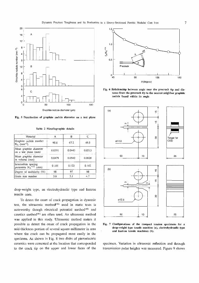
of circle. Figure 5 shows the distribution of graphite
nodule on a test plane. Metallographic details. such as
graphite nodule and grain size are listed in Table 2. The
de且nition of inteq;)article spacing depends on interaction
between a particle and the phenomenon under considera-
tion. Figure 6.shQws the relationship between the angle
just ahead of the precrack tip and the expected value of
distanceξA fナom the precrack:tip to the center of the
nearest neighbors of nodules within the angle. W6 use
NA-1〆2 as a parameter of internodule sp.acing.
3.2Mech勘nical property Ib.sting
Tbnsile specimens with a diameter of 4 mm and a
gage length of 20 mm were tested in an Instron machine
◎
.集
♂.9
のヘ へ ・’.、\
ン~1
.◎
●1・・ I,)
一\●.\・
./ 昌
’(b)L』
●.
1
●)・1
◎ゾ1
画
ジ_\./蜜’
》
曵Photo.10ptical microstr皿ctures of Materials A(a)β(b)and C(c)
and a high rate tensile testing machine. Impact tests were
carried out on the standard V-notched Charpy specimens
and on the bend specimens with machine notch of O.06
mln in root radius and of 2 mm in notch depth instead of
Vnotch.
3.3Frε巳cture Toughness Testing(48・49)
Static and dynamic elastic-plastic f止acture toughness,
Jlc and Jld, respectiv.ely, were measured by the multiple-
specimen and single-specimen techniques according to
ASTM E813-810r JSME S OO1. The specimen.s were
fatigue precracked CT specimens of 25 mm in thickness
as shown in Fig.7. The testing machines used were the
㍗ε
ε
δ
ρ慈
⊆
皇君
8
黛でユ鰻
σ
20
で6
12
8
4
o
12
8
4
0
8
4
0
Dynam{c Fracture]翫)“ghness and Its Evaluatlon in a Heavy-Sectioned Ferri£ic Nodular Cast Iron
0
t5
7
睾
1く
ζ
が
1.0
0.5
0
Precrack
θ
50 100
Graphite nodule diameter(μm)
唯50
Fig。5 Distribution of gr日ph批e nodu萱e diameter on a test plane
勲ble 2 Metallographic details
Materia1 A B C
Graphite nodule numbermA(mm}2) 9α6 67.2 49.5
Mean graph{te diameter
nn a teSt plane(mm)α0391 α0443 0.05匪3
Mean graphite dlameter
奄氏@volU鶏e(mm)0.0479 0.0542 0.0628
Internodule spacing垂≠窒≠高?ter NA-112(mm) 0,105 0,122 0,142
Degree of nodularity(%) 98 97 98
Grain slze number 5.6 5.1. 4.7
45 90
θ(degree)
435 180
Fig。6Reiationship between ang垂e near the precrack tip a脳l dis・
tance from the precrack tip重。重he nearest賑eighbor graphite
nodu且e fbund w虻hin its a賑g藍e
(a)
の”
1
一十一
1
の。 γ
一一一一一一
1
一十一 8014.0
50 13
Target for
COD
drop-weight type, an electrohydraulic type and Instron
te】ユsile ones.
脳)detect the onset of crack propagation in dynamic
test, the ultrasonic method(39)used in static tests is
noteworthy though electrical potential method(40)and
caustics method(4D are o衰en used. An ultrasonic method
was applied in this study. Ultrasonic method makes it
possible to detect the onset of crack propagation in the
mid-thickness portion of several square mil玉imete「in a「ea
where the crack can be propagated most easily in the
specimen, As shown in Fig.8two disks of piezoelectric
ceramics were cemented at the location that corresponded
to the crack tip on the upPer and lower faces of the
25
(b)
σり
1
卑
012.5
響
50 13
8
Con最gurations of重he compact tension
droP鱒weight type tensi且e machi無e(a)
a甑dl無StrOn tenSi塵e maChineS(b).
25
Fig.7
」
specime無s fbr a
,e且ectrohydra岨。 type
specimen・Variation in ultrasonic reHection and through
transmission pulse heights was measured. Figure g shows

8
PiezoelectriC Ceramic
%kashi YASUNAKA
Load
ρ 噂f 、
霧
層\
’
◎聖 、 、 、 、
@、Utrasonic餐aw
、@ 、@ ρ ・@ 爵 ρ
ノ陶7孕で、
コCジ・detector
夢 , 、 、
、ヤ 1A、 ■
、 1、 、
、 暉
’ 吻、
層uらξ,
@、@ 、@ 、
、
、 , 飼
@ヤ “ “
C“覗幽
幽馬
、
Eσ’l F 崖 、@ 、@、 、
@ 1A』’
Fig.8Schemat莫。 illustraIio鳳of measuri離g the onset of crack propa-
gatlon by aR u匡trasonic method
z潔 ユ
℃
o」
35
30
25
20
霊5
10
5
0
0.0 0.2 0.4 0.6 0.8
Load一}ine displacement(mm)
tO 1.2
≧]
口=
⊃
だ。
’盃
=Φ
勲コ
α
.9
ぢ
父
b
≧1
ト
⊃
三
〇’6
=Φ
皿コ
α⊆.9
霧
’姦
2響
各コ9二←
typica正changes in pulse height under static test. The
onset of crack propagation is shown by the arrows. The
similar change under dynamic test in the drop-weight
type testing machine is shown in Fig.10. Re丘ection
method was ef艶ctive in this case. Re員ection pulse height
began to i難crease at the moment of impacしThis was
followed by another abrupt and disco誼inuous change
with crack:propagation. The onset of crack propagation
occurred befbre reaching the maximum load.
至nthe range of tensile speed below l ms 1, the load
measured by the upper load cell was in good agreement
with that estimated by back-face strain. Therefbre, Jld can
be calculated by the fbllowing equation(42)applied in
statlc test:
」IC,∫1d;Af(・/w)/(Bb)._.___.__._(2)
where A is the area under Ioad and load-line displacement
record, a is the precrack length, b is the initial uncracked
ligament, W is the width of specimen, B is the thickness
of specimen, and
Fig.9男yp長ca翌variation i鳳裂oad and u夏trasonic pulse height showing
the onset of crack propagatio曲y the arrows under stat養。 test
in an Instron machine
40
30
Z邑。-20忌
2
10
o
P
Onset of crack
propagation
u
1.5
〉 コ1.0 葛
璽
墜
&
碧
霧
田
。,5蓄
・(・/W)・・(1・αソ(1・α2)
α一
o(・・/・)・+・(・・/・)・・}1/2一{(・・/・)・1}”(3)
0 0.4 0.8
Load-liPe disp[acement(mm)
1。2
0
Fig・豆0野pica震variation in load and岨trasonic reHection pulse
he董ght showing the onset of crack propaga重ion by tke arrow
under dynam童。重est i融adroP・weight type Iensile machine

600
Dynamic Fracture]殴)ughness and ks Evaluation ln a}leavy-Sectioned Ferritlc Nodular Cast Iron
( 飢 Σ £」= σ}
6$5窃栃働て)’?糞唇〉ト
(
に.9
罵
02田
500
400
300
200
20
鷹0
0
●
O A△ B
ロ C
臼
●● TS
O YS
○○ ○
詮○
厓A 〔] △
50 壌00 150 200 250 300
Temperature(K>
Fig・11 E旋Ct Of tempera重Ure On tenSi藍e prOper重藍eS
25
20
會ねユ9)15ゆ5
冨
毬10馨
5
0
150 200 250
Temperature(K)
300
Fig.13 Charphy V-notch i㎜pact energy curve
350
400
350
(窪芝 300ζり
250
200
1r5 104 10-3 10-2 10”1 100 灌01 102 Strain rate(S-1>
F養9.12E縦lct of strain rate on yie藍d stre卿h at room tempera加re,
Material A
4.Mech段n韮。段韮Properties(49・51)
4.笠Tensi韮e段勲d Ch紐rpy Impact Properties
The effbct of temperature on tensile properties is
shown in Fig.11. Strength was insensitive to graphite
distribution. Figure 12 shows the dependence of O.2%
proof yield strength on strain rate at room temperature.
The result of V-notch Charpy impact test is shown in Fig.
13.The absorbed energy in the upper shelf region was l 7
∫and the absorbed energy transition temperature was 253
K.The data indicate a small scatter even in the transition
「eglon・
9
4.2Ybung,s Modu1HS
Ybung’s modulus E can be calculated ffom the com-
pliance C of CT specimen by the fbllowing equation(43):
E一(1/CB){(W・・)/(W一・)}2
2.1630+正2.219(a/W)
)3+20.609(・/Wプ一〇。9925(a/W
-99314(a/W)5
一20.065(a/W)2
(4)
The results are illustrated by Fig.14. Relationship
between Ybung’s modulus E and temperature T(K)was
represented by the fbllowing equation:
E=1965-0.066T
5.Fractureτbughness(49-51)
(GPa)...___.. (5)
5・1 】Ef色ct of】[nternodu璽e Spacing
Figure l 5 shows the∫一R curves obtained by static
食acture toughness tests at room temperature.茎n these
specimens tested, stretched zone was not observed, and
crack blunting line was not able to be measured clearly.
Therefbre, the intercept between the regression Iine and
the crack blunting line given by the equation J=2σf△a
was identified as∫lc. Here,σf is the effbctive yield

10
200
190
雪
5uoE で80ρ
oコ。
>
170
160 100
Takashi YASUNAKA
灌50 200 250
Temperature(K>
300
Flg.14 Y6ung,s mod蜘s as a function of垂empera加re, Material A,
100
50
40
f∈も
邑
寄30
20
O RT
△ 233K
100
ぐEもこ「
110 120 130
NA-1尼(μm)
Fig.16 Rela重lonship between Jlc and Nパ112
and 233 K, Ma重erla監A
140 150
80
60
40
20
0
O A
△ B
ロ C
J=2σ1△a
60
at room重emperature
50
40
多
重30モ「
20
10
0
O A
△ B
〔] C
β
φ
ノ
’
.(為_3
ノ
406ノ
蟹
100 150
0 0.5 tO
△a(mm>
t5 2.0
200 250
Temperature(K)
300 350
Fig.17 E焼ct of temperatロre and g即hite distributio鷺on Jlc
Fig・15」・R curve under stat藍。 test at room temperature, in藍重ial
stress in重ensity rate of O.42 MPam豆!2s4
strength and△a is the孟ncrement of crad(歪ength. The JKc
increased in the sequence of Materials A, B and C;∫夏c
was infhenced by graphite d重stribution. The reiationship
between parameter of intemodule spacing and Jlc in the
upper shelf region is shown in Fig.豆6. Fracture toughness
Jlc increased w歪th increasing Paramαer of internodu】.e
spaClng・
The ef色ct of temperature on Jlc is shown in Fig.17.
The data plotted by the solid symbols in the丘gure
indica£e those obtained by the multiple-specimen tech-
nique. UpPer she歪f region existed until temperature
decreased to about 200 K. In the upPer shelf region, in
whlch含aαure apPearance was ductile one, Jlc increased
with decreasing temperature. Further decrease in tempera-
ture led to an increase in cleavage ffacture resulting in
decrease in Jic;∫lc decreased with increase in percentage
of brittle ffac加re appearance. At ear至y stage, cleavage
倉acture surねce o負he order of o簸e grain size was isolated
each other. In the ductile-brittle transition region, dif飴rL
ence between JIc values in Materials A, B and C was not
observed。 This may be attributed to little(iiff6rence i簸
grain size. Transition temperature was 188 Kl。 Crack
propagation in the upPer shelf region occurred

Dynamic Fracture Tbughness and Its Evaluation in a Heavy-Sectioned Ferritic Nodular Cast Iron
60
11
80
60
{
隻40ζ
20
0
MateriaI
O A
△ B
ロ C
J=2σ ∠a
50
40f鳶エv30 9つ 自
「 20
10
0
K(MPa・m112・s㎜b
O 4.2x10滞1
△ t2×103
ロ歪.0×105 0
△
△
△
t5
100 150 200 250
Temperature(K)
300
Fig.19 Variation in fracture toughness as a負mct量on of temperature
With VariOUS StreSS in重enSity raIeS
0 0.5 tO
∠a(mm)
F19。18」・R curve u麟der dynamlc重est at room temperature, in麓iaI
stress intensity rate of 6.7 MPam112s-1
predominantly by void growth around graphite nodule
and coalescence.
Figure 18 shows the∫一R curves at dK/dt of 6。7
MPam112s-1。 Dynamic elastic-plastic ffacture toughness Jld
was influenced to a less extent by graphite nodule spac-
ing. In the case of larger dK/dt, experime凪al accuracy
was reduced, so that the diff6rence betwee簸Jld values of
Materials A, B and C was not found experimenta豊ly.
5.2Effbct of Stress Inte鰍sity Rate
The eff6ct of dK:/dt on倉acture toughness is shown in
Fig.19. Upper shelf ffacture toughness was increased
with increasing dK/dt. Ductile-brittle transition tempera-
ture was naturally raised with increasing dK/dt. Depen-
dence of f士acture toughness and critical crack tip opening
displacement on dK/dt is demonstrated in Fig.20. Within
this range of dK/dt, specimens were fractured in ductile
mode at room temperature. UpPer shelf f士acture tough-
ness was Iinearly related to the logarithm of dK/dt. Crack
tip opening displacement(CTOD)can be calculated from
the following equation specified by British standard(44):
CTOD・K2 iレv2)/2σ.E _.(6)
+0.46(W-a)Vp/(0.46W+054a)
where K is the stress intensity factor,σY is the yieid
strength, v is Poissoゴs ratio, and Vp is the plastic compo-
nent of load-line displacement. The second term of the
right side of this equation is the plastic cornponent of
CTOD and is denoted by CTODp亘、、ti、 distinguishing it
倉om total CTOD(CTOD吐。t、1). Especially, the dependence
of CTODpl、、ti、 on dK/dt waS Small. Therefbre, the increase
in食acture toughness with increasing dK/dt is mainly
attributed to the increase in strength.
The effbct of dK/dt on transition temperature is
shown in Fig.21.There was a linear relation between the
transition temperature and the logarithm of dK/dt. In
addition, it should be noted that the transition temperature
of this material was equivalent to that of a low carbon
steel,
5.3Fractureτbughness Parameter
Plane strain fracture toughness divided by yield
strength as a function of temperature is shown in Fig22.
Static and dynamic plane strain fracture toughness, Klcσ)
and Kld(J)were estimated from J夏。 and Jid, respectively.
The K values were converted by the fbllowing equation:
K一{EV(1一・2)}i/2.…..……………_.……(・)
Yield strength was estimated using the equation of nomi-
nal limit load of CT specimen(43)on the assumption of
constant yield ratio. In the upPer shelf region, Klc(J)/σY
and Kld(∫)/σY were kept constant regardless of tempera一

12 肱kashi YASUNAKA
f∈誘
邑 2コ 重
つ
50
40
30
20
40
O
o CTODtotal
△ CTODplastic ○
○○
○
○
101 歪02 歪03 104 k(MPa・mI/2・s-1)
100
80
倉60 、∋
040 0
ト 020
10-1 歪oo 105 106
0
寒ε
匠
〉・
o、ど
〉::
o、ゴ
15
10
5
0
K(MPa・m112・s司)
0 4,2x10⁻¹
△ 1.2×103
ΩtOx105
○
□
歪00 150 200 250
Temperature(K)
300
罫ig。22 Fracture toughness norma叢ized to yie置d strength as a fロ賑。-
tion of重empera加re w醗h var董ous s重ress intensity raIes
Fig.20 冠挽ct of stress intensity ra重e on fracture toughness and
CTOD at room tempera加re in the upper shelf region
240
邑
Φ220当
筍お
ユε2002ぼ・9
’あ
岳歪80㍍
160
歪0-2 100 102
K(MPa mv2・S昌)
104 106
Fig・21 Ef艶cI of stress intensity rate on fracture toughness trans童幽
tio賑temperature
ture and dK/dt。 This fねcture toughness parameter may be
regarded as a material constant of this material.
5.4Estimation of Fracture lbughness from Sma韮l S量ze
Specimen
There are various dif丘culties in measuring dynamic
fracture toughness of f6rritic nodular cast irons. It is
prefbrable to estimate the behavior of倉acture toughness
at the predetermined dK/dt ffom the results of static
倉acture toughness tests and impact tests of small speci-
mens. The results of a鍛lmpact bend£est using small
specimens with machined notches are shown in Fig.23.
The dK/dt in the impact test can be estimated from the
impact speed and the dK/dt in a static bend test. When
the root radius of machined notch is in由e same order of
magniωde as internodule spacing, the sharpness of
machined notch may be equivaient to that of fatigue-
cracked notch because of the existence of graphite
nodule. In such a case, the estimation of the behavior of
倉acture toughness might be possible由rough percentage
of brittle倉acture apPearance in倉ont of the precrack tip.
In this study, increase in percentage of brittle ffacture
appearance of more than 50%led to rapid decrease in J正d.
The co簸ditions of 50%br隻ttle ffacture appearance cor-
responded to that of the lower limit of temperature in the
upper shelf region. It was fbund that the temperature at
the beginning of embrittlement in fracture toughness and
the corresponding temperature of 50%brittle ffacture
apPearance in CT or machine-notched specimens were
iinearly related to the Iogarithm of dK/dt.
Figure 24 shows a method to estimate the behavior
of ffacture toughness at the predetermined dK/dt. Point A
is obtained by static test usingσr specimens, whereas
Point B is obta玉ned by impact test usi敷g small bend
specimens w貢h machi簸ed notches. In the figure, Ti is the
lowest temperature of upper shelf region and Ts is the
50%brittle倉acture transition temperature. Point D is
determined ffom Point C that corresponds to the predeter-
mined dK/dt o簸the line AB。 Thus, the relationship
between Kld/σY and temperature ca簸be estimated,

20
Dynamic Fractuごe Tbughness a艮d Its Eva垂uat重on i江aHeavy-SectiQned Ferri毛ic Nodular Cas毛Iron
、 あ9の8
9£8ミ
15
10
5
0
oAbsorbed energy●Brittle frac室ure
surface
’ ’ ’ ! ノ ! !
! ∠ 1
_一一一一’
!!
’
!!
一一一岬一欄糟哺 ノ’ノ
歪00
75
50
25
150 200 250 300
Temperature(K)
3500
2ヨむ要
い盈甚お
芒Φ9①
巳
F韮g。231mpact energy a識d percentage of bri棚e fracture appearance
of重he mach韮ne・notched bend specimen as a fhnction of
tempera加re. The broken蓋韮籍e shows Charpy V・notch
impact energy c装rve,
2ヨ頸
①
皿
Φト
KI、ノσY
Dこ う ヨ り れ わ ゆ は む コ
鞠 鞠 贈 喝
馬鱒、馬
、、、
、
o
一.一C
l
l
od l 峯3 の 1 短トー
のO l
_一@ 一一一一一一一一一一一一トー
IA l
l :
l l
8 ..
;
ld ol。o 咀創建
贈8δ踊
1岳
l
l
コ コ ト コ
l
l
l
Ts
TI
2ヨ歪
ΦΩ.
∈…
Φ
Klc/σY log K
Fig.24 Estimation of dynamic fracture toughness be血av量or by static
fracture toughness tests and impact tests with sma監監
machine・no重che“bend specimen
13
dK/dt, the refbrence curve relating to Kld and relative
temperature may be established. In general, however, the
prediction of unstable frac加re on the basis of crack
initiation criterion seems to be reasonable. Here, the
analysis based on Iinear elastic ffacture mechanics is
employed.
Variation in K玉d(J)with temperature is shown in Fig.
25.The shaded area in the figure shows the range of
食acture toughness values reported by Arai et al.(26)In the
region shown by a lighter shade, plane strain f士acture
toughness was valid. On the other hand, in the region
shown by a darker shade, namely, in the upper shelf
region, plane strain ffacture toughness was invalid regard-
Iess of using CT specimens of 150 and 200 mm in‘
thickness. The upper shelf ffacture toughness in this study
was smaller than that reported by Arai et al. The critical
allowable f【aw size can be calculated by these data.
Analysis of unstable ffacture, however, can be simpli負ed
by the above-mentioned倉acture toughness parameteL
For example, it is assumed that a semi-elliptical
surface crack exists perpendicular to the surface of thick
plate as shown in Fig.26. A load that is superimposed by
tension and bending is applied to the plate. The stress
intensity factor becomes maximum value at Point A
under the condition described later There are many
papers that give the calcul飢ion of the stress inte駐sity
factor in such a case. According to Ishida et al.(45), the
stress intensity factor at蔓)oint A is represented by the
fbllowing equation:
K一二)1/2(σM馬・σ、恥)_.____(8)
6.Ev31uat韮on of Fracture Toughness(51・52)
In the f6n陰itic nodular cast iron, it 量s necessary to
evaluate upPer shelf 倉acture toughness fbr preventing
unstable ffacture in the upPer shelf region as well as
ductile-brittle transition temperature. An attempt has been
made to recommend the design criterion by the conven-
tional method on the basis of strength and static ffacture
toughness(45). The resistance of crack propagation in this
material is relatively small. It is difθcult to establish the
Pellini-type食acture toughness ref6rence curve because of
the difHculties in measuring nil ductility transition tem-
perature by dynamic tear test. Within the limited range of
where both FM and FB are the functions of b/a and b/t,
which are given by polynomials. The total stress on出e
surface of plate is expressed by:
σ=σM+σB._._._....._._.___,_.. (9)
WhenσB/σM=3, the stress intensity factor is given by:
K・σM(痴)1/2低,+碑、)._.______(10)
Relationship between stress on the plate sur飴ce and

14
Temperature(℃)
一120 一で00 -80 -60 -40 -20 0
笛akashi YASUNAKA
20
歪50
f琴100
窪
}
50
0
k(MPa・m112・s 1)
● Kld(J) 1.2×10³
▲ Kld(J) tO x 105
Klc㈹ASTM >300纏懇Klc(J) >300
く一一一一一
く一一一ロ冒 く一 唱 一 冒 一 ” 桶 脚
’ ’冊 腰 隔 一 幽 一 ’
’ ’ ’ ’一 ’
’ ’’
:
”崖冊刷
n 堂, ”
罐 A
螺
:
:
匡 → …
→→ ___レ じ冊ノ騨 曽 一 一 一 一 一 冒 盟 曜 彌
’ _____→
o〕
o
Σ
o
一一一「一rrr一一幽
L、 、、」
剰
150 200 250 300
Temperature(K)
Fig.25 Dynamic p匪ane stra産n fracture tough賑ess as a hmction of
tempera加re
・「
critical depth of surface Haw bc can be determined from:
σ/σY一(K・d/σ・)(1・βソ{(励・)’/2(恥鮒}(11)
Here, b/a ahd t are assumed to be 1/4 and 400 mm,
respectively. In the upper shelf region of this material,
Kld(J)/σY is regarded as a constant as mentioned bef6re。
When stress on the plate surface is constant, uni負)rm
tension(β=0)results in the minimum value of criticaI
Haw depth. Relationship between stress under uni{brm
tensionσT and critical naw depth bc(T)is shown童n Fig.
27,The solid line in the丘gure shows the relation fbr the
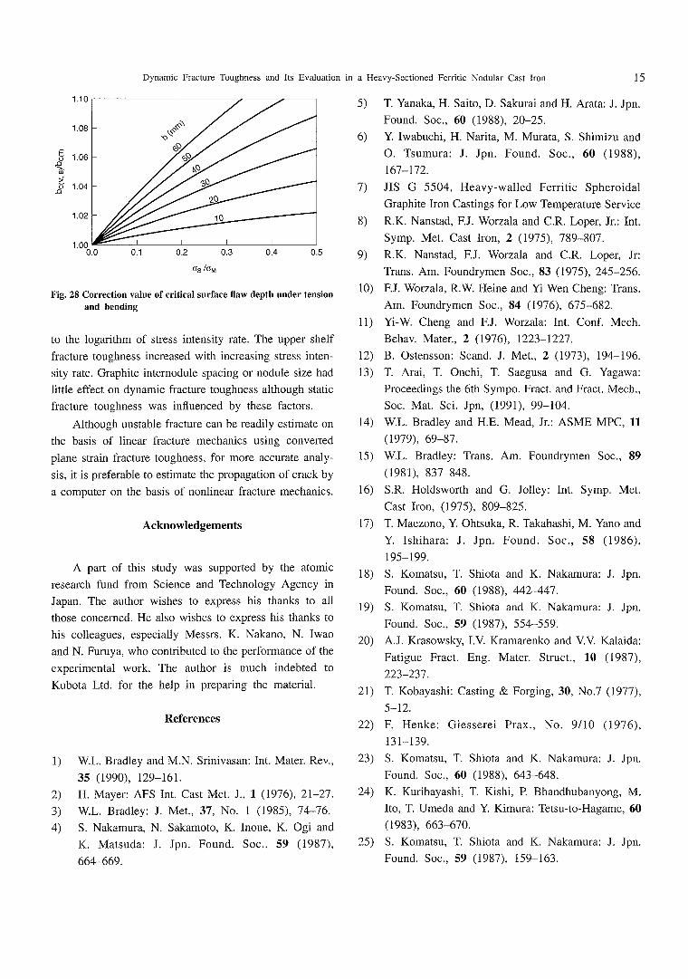
material used in this study. Ifσis constant, the critical
Haw depth bc(Mβ)increases with increasing bending stress
σB.Relationship betweenσB/σM and bc(M,B)A)c(T)is shown
in Fig.28.
7.Conduding Remarks
Heavy-sectioned castings of fbrritic nodular cast iron
have become to be produced recently, and this material
has attracted particular attention as an econornic one。
硬bughness of thls material is relatively low because of
large amount of graphi£e. Careful evaluation of tough-
ness, therefbre, is necessary in the use of this material.
However,11ttle sys£ema書ic study of dynamic fracture
toughness has been made。 In the productio簸of castings of
L,∴
Fig.26 Tension and ben(韮ing of a f童n虻e一酌ickness p蓋ate with a
semi-el騒p重ica藍s磁r鉛ce crack
60
_ 50∈
豊
ε
8 40言
9
壷30葱
馨
0 20
10
● ● ● o ●コ コ コ
曳 」 ㌔ 、 ●・・.
、瓦之瓦’㍉㍉路、、・、,、1ミ
\〉誉緊:::ト、
’●・。. ・.
B ●●。.. ’。・・。.
6、%%、%、、…...i;’
Kld…〆…mm1/2・”・・…..こ.・・・…..:=
・Oo・. ●・●●●●●
0.3 0.4 0.5 0.6 0.7 0.8 0.9 1.0
σT/σY
F孟g。27Cr託ica置sur飴ce f藍aw depth as a危mction of unifbrm£ens丘藍e
stress in the upper shelf region with normalized fracture
toughneSS
this material, relatively much know-how is required, and
this enables manufacturers to produce castings wi芒h
somewhat diffαent quality. The microstructure of f6rrite
nodular cast iron used in this study was excel玉ent one
having low volume fraction of pearlite and high nodular-
ity。 Behavior of fねcture tough賎ess in regard to tempera-
ture and 歪oading rate has been stud童ed。 In this study,
elastic-plastic丘acture toughness was adop!ed as倉acture
toughness because plane strai11倉acture tough簸ess was
probably not effbctive in t鼓e upPer shelf region even if
出ick specimens were used.
Embri亡tlemen亡occ膿red adowとemperatαre and frac-
ture toughness transition temperature was linear圭y related
ε
8\璽三〇
.Q
1.10
Dynamlc Fracture]文)ughness and Its Evaluation in a Heavy-Sectioned Ferritic Nodular Cast三ron
1.08
tO6
tO4
1,02
1,00
♂
塩O
0.0 0」 0.2 0.3 0.4 0.5
σ8ノσM
Fig.28 Correction valロe of cr辻ic3艮sur飴ce Oaw dep重h under tensio駐
and bending
to the logarithm of stress intensity rate. The upper shelf
fracture toughness increased with increasing stress inten-
sity rate. Graphite internodule spacing or nodule size had
Iittle ef陀ct on dynamic fracture toughness although static
倉acture toughness was inf玉uenced by these factors.
Although unstable fヤacture can be readily estimate on
the basis of linear fracture mechanics using conve宜ed
plane strain fracture toughness, fbr more accurate analy-
sis, it is prefbrable to estimate the propagation of crack by
acomputer on the basis of nonlinear貸acture mechanics・
5)
6)
7)
8)
Acknowledgements
Apart of this study was supported by the atomic
research fund ffom Science and馳chnology Agency in
Japan. The author wishes to express his thanks to all
those concerned.}{e also wishes to express his thanks to
his colleagues, especially Messrs. K. Nakano, N. Iwao
and N. Furuya, who contributed to the per拓㎜ance of the
experimental work, The author is much indebted to
Kubota Ltd. fbr the help in preparing the material.
1)
2)
3)
4)
Re艶rences
WL. Bradley and MN. Srinivasan:Int Mater. Rev.,
35 (1990), 129-161.
H.Mayer:AFS至nt. Cast Met J.,1(1976),21-27.
W.L. Bradley:J. Met.,37, No.1(1985),74-76.
S,Nakamura, N. Sakamoto, K. Inoue, K. Ogi and
K.Matsuda:∫. Jpn. Found. Soc.,59(1987),
664-669.
9)
10)
11)
12)
13)
14)
15)
16)
17)
18)
19)
20)
21)
22)
23)
24)
25)
15
T.Yanaka, H. Saito, D. Sakurai and}{. Arata:J. Jpn.
Found. Soc,,60 (1988),20-25.
YIwabuchi, H. Narita, M. Murata, S. Shimizu and
O.Tsumura:J. Jpn. Found. Soc。,60(1988),
167-172.
JIS G 5504, Heavy-waHed Ferritic Spheroidal
Graphite玉ron Castings fbr Low艶mperature Service
R.K. Nanstad, FJ. Worzala and C.R. Loper, Jr.:Int.
Symp. Met. Cast Iron,2(1975),789-807,
RK. Nanstad, F.J. Worzala and C.R. Loper, Jr:
Trans, Am. Foundrymen Soc.,83(1975),245-256.
F.」.Worzala, R’v. Heine and Yi W6n Cheng:Trans.
Am. Foundrymen Soc.,84(1976),675-682.
昭一W.Cheng and FJ, Worzala:茎nt. Conf, Mech.
Behav. Mater.,2(1976),1223-1227.
B.Ostensson:Scand. J. Met.,2(1973),194-196.
T.Arai, T. Onchi, T Saegusa and G Yagawa:
Proceedings the 6th Sympo. Fract。 and Fract. Mech.,
Soc. Mat. SciJpn,(1991),99-104.
W.L, Bradley and H.E. Mead, Jr.:ASME MPC,11
(1979),69-87.
W,L. Bradley:Trans. Am. Foundryme駐Soc.,89
(1981),837-848.
S.R.}loldsworth and G Jolley:Int. Symp. Meし
Cast Iron, (1975), 809-825.
T.Maezono, Y Ohtsuka, R.肱kahashi, M. Yano and
Y.王shihara:J.∫pn. Found, Soc.,58 (1986),
195-199.
S.Komatsu, T. Shiota and K. Nakamur縦:J. Jpn.
Found. Soc.,60 (1988),442-447.
S.Komatsu, T. Shiota and K Nakamura:J. Jpn.
Foun(至. Soc.,59 (1987),554-559.
AJ. Krasowsky, LV Kramarenko and VV Kalaida:
Fatigue Fract. Eng, Mater. Struct.,10(1987),
223-237。
T.Kobayashi:Casting&Forging,30, No.7(1977),
5-12.
F.Henke:Giesserei Prax。, No.9/10 (1976),
131-139.
S.Komatsu, T. Shiota and K. Nakamura:J.∫pn.
Found. Soc.,60 (1988),643-648.
K.Kuribayashi, T. Kishi, P. Bhandhubanyo駐g, M.
Ito, T. Umeda and Y Kimura:τbtsu-to-Hagame,60
(1983),663-670.
S.Komatsu, T. Shiota and K. Nakamura:JJpn.
Found. Soc.,59 (1987),159-163.

16
26)
27)
28)
29)
30)
31)
32)
33)
34)
35)
36)
37)
38)
セ
肱1(ashi
K.B. Sorenson and R. Salzbrenner=“The Mechan-
ism of Fracture,”ed. by Goel, ASM,(1986),
415_419.
T.Maezono, R. Takahashi and M. Suenaga:J。 Jpn.
Found。 Soc.,60 (1988),578-583.
R.Salzbrenner:J. Mater. ScL,22(豆987),
2135-2147.
Y Iwabuchi, H. Narita and O。Tsumura:J. Jpn.
Fou韮d. Soc.,60 (1988),215-220.
T.Kobayashi and S. Nishi:J. Jpn. Found. Soc.,52
(1980),76-87,(Communication paper fbr the 46th
Int. Foundry CongL, Madrid, Spain).
T.Luye簸d麺k and H. Nieswaag:至nt. Foundry CongL,
(1982), 至一正3.
T。Kobayashi, H. Yamamoto and K. Matsuo:Eng.
Fract. Mech.,30(1988),397-407.
‘‘
qesearch on Quality Assurance of Ductile cast
lron Casks,”Quality Assurance Committee on Duc-
tile Cast Iron Casks, CR肥PI Report,(1990).
E.F両ii, Y Sakai and Y Ando:J. Tbs. EvaL,14
(豆986), 181-190.
T.Kobayashi,1. Yamamoto and M, Niinomi:Eng.
Fract. Mech,,24(1986),773-782.
A.Kl. Shoemaker and S。T. Rolf6:Eng. Fract. Mech.,
2(1971),319-339.
WN. Shaq)e,∫L and JM Shapiro:∫.艶st. EvaL,18
(1990), 38-44.
MR Bayoumi・∫・R・Klepaczko and M耳・Bassi甲:J・
Test. Eval.,王2(1984)316-323.
YASUNAKA
39) K.Hirano, H. Kobayashi and H. Nakazawa:」.艶st.
EvaL,13(1985),356-362.
40) J.R.∫oyce and C.S. Schneider:J. Tbst. Eval.,豆6
(1988),257-270.
41) J.F. Kalthoff:至nt.∫. Fract.,27(1985),277-298,
42)ASTM Standard E813-81, Standard騰st fbr Jlc
43)ASTM Standard E813-87, Standard Tbst fbr Jlc
44)
45)
46)
47)
48)
49)
50)
51)
52)
British Standard Method 7448(1991), Fracture
Mechanics, Tbughness艶sts, Part 1.
M.W. Schwartz and L. Boyce:“Ductile and Brittle
Failure Design Criteria fbr Nodular Cast Iron Spent-
Fuel Shipping Containers,”US DOE Rep.,
UCRL-53046,(1983).
M.Ishida, H. Noguchi and T. Ybshida:IntJ. Fract.,
26 (1984), 157-188.
T.Yasunaka, K, Nakano and T. Saito:1SIJ Interna-
tional,31 (1991), 298-303.
T.Yasunaka, N。 Iwao, N. Furuya, H. Yamawaki, S.
Matsumoto and Kl. Kimura:Tbtsu-to-Hagane,71
(1985), 1398-1404.
T。Yasunaka, N. Iwao, N. Furuya, Kl. Kimura and H.
Yamawaki:J. Soc. Mater. Sci. Jpn.,33(1984),
1336-1341.
K.Nakano and T. Yasunaka:丑)tsu-to-Hagane,78
(1992),926-993.
T,Yasunaka and K. Nakano:Proc. the lOth Int.
Symp. Packaging and Transportation of Radioactive
Materials,(1992),1304-1310.
Kl. Nakano and T. Yasunaka:Tetsu-to-Hagane,80
(1994),330-335.
「
Dynamic Fracture Toughness and Its Evaluation in
aHeavy-Sectioned Fe㎡tic Nodular Cast Iron
by
Takashi YASUNAKA
NRIM Special Repo直
(Research Report)
No,94-02
Date of issue:31March,1994
.r・
ノ
Editodal Committee:
Kazuh廿。 YOSHIHARA._.Ch謡㎜an
Saburo MATSUOKA_Co-cha㎞1an Hirohisa皿ZUKA
Kazuo KADOWAKI
Hideyuki OHTSUKA
Yoshio SAKKA
Kohei YAGISAWA
,
Publisher, Contact:
Toshikazu ISHII
PIanl盛ng Section, AdministraUon Division
National Research hlstitute fbr Metals
2-3-12,Nakameguro, Meguro-ku, Tokyo l 53, Japan
Phone:+81-3-3719-2271 Fax:+81-3-3792-3337
グ ヒを:!、
Copyrigbt◎1994
’ by
National Research Institute fbr Metals
Dhector-General Dr. Kazuyoshi NH
Typeset using the SGML by Uniscope, Inc.,Tokyo

8
Dyn㎜ic Fracture Tbug㎞ess and Its Evaluation hl
aHeavy-Sectioned Fenitic Nodular Cast Iron
by
T瓠(ashi YASUNAKA
㎜Special Repo丘 (Research Report)
No.94-02
Contents
Absαact・.......・.......●...●”.”6’”9,’.’6.’●’.’●◎......’”●’6..”●”6”.’’”.’’’’”.”,.”...’....’’”..9...”.’..膠’....願..’●....
1.Introduction..9....................,...9.........噛.,....9,.,.,..........。.畢.....,.......9...............,9...........9幽3.......
f.10切ective of This Study_.._._......_._......._..........._........_,.,......._._..__.。..,..
1.2Historical Review_______..___.____..___.___.___._,_._..__._.
1.2.1Static Fracture 1㌃)ughness and Specimen Thic㎞ess.._.._....__._._...。._..__......
1.2.2Chemical Composition.._._、._......_._......。......_.......__.,._..._.._..._.___.
1.2.3 Pearlite.,.._.._...『...............,._._._.............9.9.........,...9..,....._....6,...._._...曹.......
1.2.4Graphite Nodularity______...._..._。.........,.._._........_._..__...._...._..。._
1.251ntemodule Spacing and Nodule Size of Grap1オte..____.__._....._................_
1.2.6Dynamic Fracture Tbughness.。...,...,.........._........_._.._..........__........._..._._
2.Development of a Drop-weight Impact Tbsting Machine____._.._____.._.____
3.Experimental Procedure______・.___._._.__..._...,__..._......................_.._...
3.1Materials___,_._____.__.....__.___._...._____.___._.______.
3.2Mechanical Propertyτもsdng..__.__....._.._.。_....._...._............._.............___.
3.3 Frac田re Tbughness Testing_____._____._...__.____..___,.,._....._,_.
4.Mechanical Prope質ies______....._.,,_.....。_.........._.._._,......_..._...._.....,._.._
4.l Tbnsile and Charpy Impact Properties_._.,。.._.._..._....._._.,....._._,_.._.,.._._
4.2Ybung’s Modulus_____.........._._.,_...._._.__.._,__,__._,_...__....__.
5.Fracture Tbughness_._.____._.........._.._.,._,...,.,_......,........_...._.._..._....._....
5.1Ef色ct of Intemodule Spacing_.._..______..__.____..__._.._._...._._,.∴
5.2Effbct of Stress Intensity Rate____.__.__.__..______...___....__._....
5.3Fracture Tbughness Parameter______.____.__.______._......._...._,._.
5.4Estimation of Fracture Tbughness丘om Small Size Specimen__.___..._..._...........
6.Evaluation of Frac1血re Toughness__.__._,_,____.___.__._..._...,._....._..._.
7.℃oncluding Remarks...._........._..._.._._._..,_._.___._.。_...,_,.._.._._._...._...
Ac㎞owledgements__.___..___...______.____..__.__..____。______
Refbrences...._.,............._.._.._..._...._.._......._.....。.........._.._.._._..._...................
1
2
2
2
2
2
3
3
4
4
5
6
6
6
6
9
9
9
9
9
11
11
12
13
14
15
15
・ピ..
(
ぞ
,
、
’