dynamic control- flow graph (dcfg) and dcfg-trace format
TRANSCRIPT

Copyright© 2015 Intel Corporation. All rights reserved.
Dynamic Control-Flow Graph (DCFG) and DCFG-Trace Format Specifications FOR FORMAT VERSION 1.00

Copyright® Intel Corporation
Page | 1
CONTENTS
1 Overview .............................................................................................................................................. 3
1.1 Data-interchange format ............................................................................................................. 3
1.2 Conventions ................................................................................................................................. 3
1.2.1 Hex values ............................................................................................................................ 3
1.2.2 Tables .................................................................................................................................... 3
1.2.3 ID numbers ........................................................................................................................... 4
1.2.4 JSON objects ........................................................................................................................ 4
1.2.5 Tags and table headers ........................................................................................................ 4
1.2.6 White space .......................................................................................................................... 5
2 DCFG contents...................................................................................................................................... 5
2.1 Example ........................................................................................................................................ 5
2.2 Top-level structure ....................................................................................................................... 6
2.3 Version .......................................................................................................................................... 7
2.4 File names ..................................................................................................................................... 7
2.5 Edge types .................................................................................................................................... 8
2.6 Special nodes .............................................................................................................................. 11
2.7 Processes ..................................................................................................................................... 12
2.8 Process Data ................................................................................................................................ 12
2.9 Images ......................................................................................................................................... 13
2.10 Image Data ................................................................................................................................. 14
2.11 Symbols ...................................................................................................................................... 14
2.12 Source information ..................................................................................................................... 15
2.13 Basic blocks ................................................................................................................................ 16
2.14 Routines....................................................................................................................................... 17
2.15 Loops .......................................................................................................................................... 18
2.16 Edges .......................................................................................................................................... 19
3 DCFG-trace contents .......................................................................................................................... 20
3.1 Top-level structure ..................................................................................................................... 20
3.2 Version ......................................................................................................................................... 21
3.3 Processes ..................................................................................................................................... 21
Copyright® Intel Corporation
Page | 2
3.4 String dictionary .......................................................................................................................... 21
3.5 Transition table .......................................................................................................................... 22
3.6 Thread data ................................................................................................................................ 23
3.7 Trace data ................................................................................................................................... 24
3.7.1 Converting an edge-id sequence string into a bit string .................................................. 25
3.7.2 Decoding a sequence of edges ......................................................................................... 26
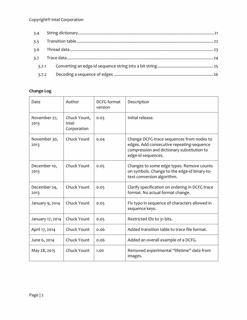
Change Log
Date Author DCFG format version
Description
November 27, 2013
Chuck Yount, Intel Corporation
0.03 Initial release.
November 30, 2013
Chuck Yount 0.04 Change DCFG-trace sequences from nodes to edges. Add consecutive repeating-sequence compression and dictionary substitution to edge-id sequences.
December 10, 2013
Chuck Yount 0.05 Changes to some edge types. Remove counts on symbols. Change to the edge-id binary-to-text conversion algorithm.
December 24, 2013
Chuck Yount 0.05 Clarify specification on ordering in DCFG trace format. No actual format change.
January 9, 2014 Chuck Yount 0.05 Fix typo in sequence of characters allowed in sequence keys.
January 17, 2014 Chuck Yount 0.05 Restricted IDs to 31 bits.
April 17, 2014 Chuck Yount 0.06 Added transition table to trace file format.
June 6, 2014 Chuck Yount 0.06 Added an overall example of a DCFG.
May 28, 2015 Chuck Yount 1.00 Removed experimental “lifetime” data from images.

Copyright® Intel Corporation
Page | 3
1 Overview This document describes the format of ASCII character streams used to describe a dynamic control-
flow graph (DCFG) and supporting data from the execution of one or more processes on a computer
processor. The adjective “dynamic” indicates that the nodes and edges reflect the actual paths
traversed during execution, not all possible paths in the processes. Also, the format contains counts
of nodes and edges from a specific execution, not just static structural data.
1.1 Data-interchange format
The character stream conforms to the JSON format described at http://www.json.org. An established
format was chosen to simplify the process of creating tools for encoding and decoding. Many JSON
parsers are available in various programming languages. JSON was also chosen because of its
simplicity and ease of storing hierarchical and array-based data, both of which are prevalent in DCFG
data. (XML was specifically not used because it does not have an efficient way to store arrays.)
The format does not specify the container for the stream. It could be stored in memory, saved in a
file (with or without text-compression), transmitted inter-process, etc.
1.2 Conventions
The following conventions are used to standardize some common idioms:
1.2.1 Hex values
JSON provides only base-10 integer and floating-point number encoding natively. Many values in the
DCFG are almost always displayed in base-16 (hex) format in other tools, such as disassemblers.
Certainly, all values could be stored in base-10 and converted by parsers, but this makes human-
reading of the values and manual correlation with other tools difficult. Thus, it is legal for numerical
values to be stored as strings in C-style encoding. Example: “0x400000” is equivalent to the decimal
value 4194304, the default load address for binaries in Linux.
Important: Certain values (like addresses) are typically stored as hex strings, and certain values (like
sizes and counts) are typically stored as integers, but this is not enforced. Parsers should recognize
both hex strings and native integers anywhere an integer is required. In the remainder of this
document, the term “integer” will be used to indicate that a number can be stored in either format.
1.2.2 Tables
JSON does not provide a native table type. Tables of data are common in the DCFG format, and the
following convention is used throughout.
Tables are stored as two levels of nested arrays. The outer array holds the columns, and the inner
arrays hold the rows. The first row contains a header for the table, consisting of an array of strings
indicating what is contained in each following data row. This is similar to data in a spreadsheet with a
header row. Example:
[ [ "EMPLOYEE_ID", "NAME" ],
[ 1234, "MARY" ],
[ 5678, "BOB" ],

Copyright® Intel Corporation
Page | 4
[ 9874, "IGOR" ]
]
Notes:
o An element in a table can be any JSON value, including objects (key-value pairs) and other
arrays and tables. This allows arbitrary construction of complex hierarchical structures
including tables.
o Some values in some tables are optional, so the data arrays do not all have to be the same
length. Any given row must consist of all provided values in a continuous sequence from the
beginning. In other words, a value cannot be omitted and then followed on the same row by
another value.
o Important: When reading, use the header to determine the column of particular data items,
not the absolute column position.
1.2.3 ID numbers
Integer ids are numbers assigned to uniquely identify different elements in a set. They range
between one (1) and 0x7fffffff, inclusive, unless otherwise noted. Negative numbers, zero (0)
and numbers greater than or equal to 0x80000000 are reserved. Parsers should always read the ids
and never assume values. In addition, there should not even be an assumption that ids
corresponding to the same element in different DCFG streams will be the same. (This does not hold
for paired DCFG and DCFG-traces, where ids are shared.)
1.2.4 JSON objects
JSON objects contain key-value pairs, where the key must be a string. To reduce ambiguity, especially
in the case where objects are loaded into map data structures with unique keys, keys will not be
repeated in a given object. Parsers should not rely on any particular order of key-value pairs shown in
examples in this document or elsewhere.
1.2.5 Tags and table headers
Pre-defined strings are used as keys in JSON objects and in table headers. These strings consist only
of upper-case letters, numbers and underscores. Example: “LOAD_ADDRESS” is used to tag the load
address for an image. An effort has been made to maintain consistency. For example, “item_COUNT”
is used to indicate a dynamic count of some type of item, and “NUM_items” is used for a static
count. An effort has also been made to use abbreviations consistently and not gratuitously. Common
abbreviations include, but are not limited to, the following:
Abbreviation Expansion
ADDR Address.
INSTR Instruction.
ID Identifier (integer).

Copyright® Intel Corporation
Page | 5
1.2.6 White space
Per JSON specifications, white space between tokens and values is optional and ignored. Specifically,
parsers should not rely on any values being on the same or different lines as any other values.
2 DCFG contents The DCFG format allows storage of information on processes, including their constituent images,
symbols, debug data, and control-flow graph defined by a specific execution of the processes.
2.1 Example
Following are excerpts from a DCFG describing a simple “Hello, World” program:
{ "MAJOR_VERSION" : 1,
"MINOR_VERSION" : 0,
"FILE_NAMES" : [
[ "FILE_NAME_ID", "FILE_NAME" ],
[ 1, "hello-world" ],
[ 2, "\/lib64\/ld-linux-x86-64.so.2" ], ...],
"EDGE_TYPES" : [
[ "EDGE_TYPE_ID", "EDGE_TYPE" ],
[ 1, "ENTRY" ],
[ 2, "EXIT" ],
[ 3, "CALL" ], ...],
"SPECIAL_NODES" : [
[ "NODE_ID", "NODE_NAME" ],
[ 1, "START" ], [ 2, "END" ] ],
"PROCESSES" : [
[ "PROCESS_ID", "PROCESS_DATA" ],
[ 13723,
{ "INSTR_COUNT_PER_THREAD" : [ 1867502 ],
"INSTR_COUNT" : 1867502,
"IMAGES" : [
[ "IMAGE_ID", "LOAD_ADDR", "SIZE", "IMAGE_DATA" ],
[ 1, "0x400000", 2112944,
{ "FILE_NAME_ID" : 1,
"SYMBOLS" : [
[ "NAME", "ADDR_OFFSET", "SIZE" ],
[ "main", "0xdd0", 128 ], ...],
"SOURCE_DATA" : [
[ "FILE_NAME_ID", "LINE_NUM",
"ADDR_OFFSET", "SIZE", "NUM_INSTRS" ],
[ 8, 25, "0xb28", 4, 1 ],
[ 8, 26, "0xb2c", 5, 1 ], ...],
"BASIC_BLOCKS" : [
[ "NODE_ID", "ADDR_OFFSET", "SIZE",
"NUM_INSTRS", "LAST_INSTR_OFFSET", "COUNT" ],
[ 4, "0xb28", 9, 2, 4, 1 ],
[ 5, "0xb31", 5, 2, 4, 1 ],
[ 6, "0xb40", 12, 2, 6, 10 ], ...],

Copyright® Intel Corporation
Page | 6
"ROUTINES" : [
[ "ENTRY_NODE_ID", "EXIT_NODE_IDS",
"NODES", "LOOPS" ],
[ 90,
[ 90, 93, 95 ],
[ [ "NODE_ID", "IDOM_NODE_ID" ],
[ 90, 90 ], [ 91, 90 ], [ 92, 91 ],
[ 93, 92 ], [ 94, 93 ], [ 95, 91 ] ],
[ [ "LOOP_HEAD_NODE_ID",
"LOOP_BACK_EDGE_SOURCE_NODE_IDS",
"LOOP_NODE_IDS",
"PARENT_LOOP_HEAD_NODE_ID" ],
[ 93, [ 94 ], [ 93, 94 ] ] ]
], ...]
} ], ...]
},
"EDGES" : [
[ "EDGE_ID", "SOURCE_NODE_ID", "TARGET_NODE_ID",
"EDGE_TYPE_ID", "COUNT_PER_THREAD" ],
[ 2887, 1741, 1742, 16, [ 1 ] ],
[ 1357, 665, 676, 13, [ 3 ] ],
[ 2888, 2424, 2069, 6, [ 1 ] ], ...]
]
]
}
Each of the different types of elements is described in one of the following sections.
2.2 Top-level structure
The top-level JSON value is an object (sequence of key-value pairs).
The major sections of the DCFG stream are tagged in the top-level object. They are listed briefly
below and are expanded in the remainder of this document:
Format version.
Lists of identifiers (ids) used to reference strings later in the stream: file names, edge types,
and special nodes.
The following data on each process:
o Process ID.
o Total and per-thread instruction counts.
o List of images (i.e., binaries and shared objects):
Load address and size.
Filename id.
List of symbols.
Source-file and line-number debug data.
List of basic block nodes.
List of routines and their constituent loops.
o List of edges, including their trip-counts per thread.

Copyright® Intel Corporation
Page | 7
Example top-level object:
{ "MAJOR_VERSION" : 0,
"MINOR_VERSION" : 6,
"FILE_NAMES" : […],
"EDGE_TYPES" : […],
"SPECIAL_NODES" : […],
"PROCESSES" : […],
}
Most of these sections and sub-sections are optional as noted below. Specifically, even though this
format is referred to as the “DCFG” format, the control-flow graph is optional; the format can be
used to store other useful information such as processes, images, symbols and debug data.
2.3 Version
The major and minor versions of the file format are listed as two separate tags in the top-level object.
Top-level tag Value
MAJOR_VERSION Integer.
MINOR_VERSION Integer.
The intention is that the DCFG format will be both backward and forward-compatible as much as
possible. Backward compatibility means that future versions should not change the pre-defined tags
or remove non-optional data. Forward compatibility means that additions should be done in a way
such that parsers for existing formats should be able to read future formats if they ignore unknown
tags.
If compatibility is broken, or if a major new feature is added, the major version number should be
incremented and the minor version number reset to zero. Otherwise, if any other format change is
made, the minor version number should be incremented.
When converted to text, the major version and minor versions are separated by a dot (“.”), and the
minor version should be displayed as two digits to allow up to 99 minor versions without confusion
due to decimal place value, e.g., 2.03 precedes 2.12.
Example:
"MAJOR_VERSION" : 3,
"MINOR_VERSION" : 4,
Indicates version 3.04.
2.4 File names
The list of file names is used to save space by allowing file names to be later referred to by their
integer identifiers rather than long strings that might otherwise need to be repeated many times.
Top-level tag Value

Copyright® Intel Corporation
Page | 8
FILE_NAMES File-name table (see below and section 1.2.2).
File-name table:
Table heading Value
FILE_NAME_ID Integer id (see section 1.2.3).
FILE_NAME String containing full path of file if known.
Example:
"FILE_NAMES" :
[ [ "FILE_NAME_ID", "FILE_NAME" ],
[ 2, “\/usr\/joe\/src\/misc\/hello-world" ],
[ 5, "\/lib64\/libgcc_s.so" ],
[ 4, “\/usr\/joe\/src\/misc\/hello-world.c" ],
]
Notes:
o As with all strings, special characters are escaped per JSON string-formatting rules.
o Parsers should not assume that ids start with one or are sequential or are in any particular
order.
o All file names used in the DCFG stream are stored in the same table, including those for
images and source files.
o This table is optional. If it is not present, no file names can be referenced in the remainder of
the data.
2.5 Edge types
The list of edge types is used to save space by allowing edge types to be later referred to by their
integer identifiers rather than strings that would otherwise need to be repeated many times.
Top-level tag Value
EDGE_TYPES Edge-type table (see below and section 1.2.2).
Edge-type table:
Table heading Value
EDGE_TYPE_ID Integer id (see section 1.2.3). Important: the ID number assigned to any given edge type is valid only within a DCFG and is not necessarily the same between any two DCFGs.
EDGE_TYPE String containing pre-defined edge type (see below).
Copyright® Intel Corporation
Page | 9
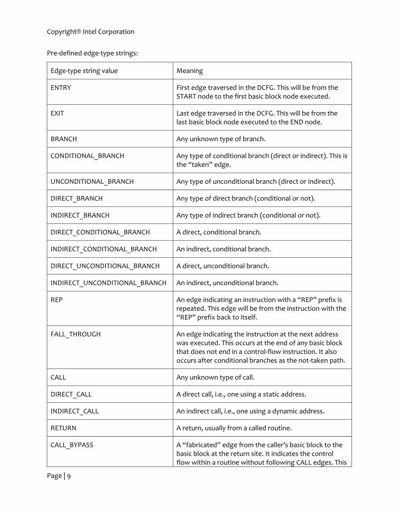
Pre-defined edge-type strings:
Edge-type string value Meaning
ENTRY First edge traversed in the DCFG. This will be from the START node to the first basic block node executed.
EXIT Last edge traversed in the DCFG. This will be from the last basic block node executed to the END node.
BRANCH Any unknown type of branch.
CONDITIONAL_BRANCH Any type of conditional branch (direct or indirect). This is the “taken” edge.
UNCONDITIONAL_BRANCH Any type of unconditional branch (direct or indirect).
DIRECT_BRANCH Any type of direct branch (conditional or not).
INDIRECT_BRANCH Any type of indirect branch (conditional or not).
DIRECT_CONDITIONAL_BRANCH A direct, conditional branch.
INDIRECT_CONDITIONAL_BRANCH An indirect, conditional branch.
DIRECT_UNCONDITIONAL_BRANCH A direct, unconditional branch.
INDIRECT_UNCONDITIONAL_BRANCH An indirect, unconditional branch.
REP An edge indicating an instruction with a “REP” prefix is repeated. This edge will be from the instruction with the “REP” prefix back to itself.
FALL_THROUGH An edge indicating the instruction at the next address was executed. This occurs at the end of any basic block that does not end in a control-flow instruction. It also occurs after conditional branches as the not-taken path.
CALL Any unknown type of call.
DIRECT_CALL A direct call, i.e., one using a static address.
INDIRECT_CALL An indirect call, i.e., one using a dynamic address.
RETURN A return, usually from a called routine.
CALL_BYPASS A “fabricated” edge from the caller’s basic block to the basic block at the return site. It indicates the control flow within a routine without following CALL edges. This

Copyright® Intel Corporation
Page | 10
is useful for implementing various control-flow and graph-traversal algorithms.
SYSTEM_CALL A special call to a system routine.
SYSTEM_RETURN A return from a system routine.
SYSTEM_CALL_BYPASS A “fabricated” edge similar to CALL_BYPASS, except for system calls.
CONTEXT_CHANGE An edge created from any non-control-flow instruction (e.g., a hardware interrupt or a faulting instruction) to a hander.
CONTEXT_CHANGE_RETURN A return from the context-change handler.
CONTEXT_CHANGE_BYPASS A “fabricated” edge similar to CALL_BYPASS, except for context-change handlers.
EXCLUDED_CODE_BYPASS A “fabricated” edge used to maintain control flow when excluding a region of code from the CFG, e.g., when skipping over spin-wait loops.
UNKNOWN Any unknown type of edge.
Example:
"EDGE_TYPES" :
[ [ "EDGE_TYPE_ID", "EDGE_TYPE" ],
[ 1, "ENTRY" ],
[ 2, "EXIT" ],
[ 3, "CALL" ],
[ 4, "DIRECT_CALL" ],
[ 5, "INDIRECT_CALL" ],
[ 6, "RETURN" ],
[ 7, "CALL_BYPASS" ],
[ 8, "BRANCH" ],
[ 9, "CONDITIONAL_BRANCH" ],
[ 10, "UNCONDITIONAL_BRANCH" ],
[ 11, "DIRECT_BRANCH" ],
[ 12, "INDIRECT_BRANCH" ],
[ 13, "DIRECT_CONDITIONAL_BRANCH" ],
[ 14, "INDIRECT_CONDITIONAL_BRANCH" ],
[ 15, "DIRECT_UNCONDITIONAL_BRANCH" ],
[ 16, "INDIRECT_UNCONDITIONAL_BRANCH" ],
[ 17, "REP" ],
[ 18, "FALL_THROUGH" ],
[ 19, "SYSTEM_CALL" ],

Copyright® Intel Corporation
Page | 11
[ 20, "SYSTEM_RETURN" ],
[ 21, "SYSTEM_CALL_BYPASS" ],
[ 22, "INTERRUPT" ],
[ 23, "INTERRUPT_RETURN" ],
[ 24, "INTERRUPT_BYPASS" ],
[ 25, "CONTEXT_CHANGE_BYPASS" ],
[ 26, "UNKNOWN_IMAGE_BYPASS" ],
[ 27, "UNKNOWN" ]
]
Notes:
o Do not assume that ids start with one (1) or are sequential or are in any particular order.
o Important: Do not assume that ids are fixed or are the same between DCFGs. For example,
an “ENTRY” node might have id=1 in one DCFG and id=3 in another.
o This table is optional. If it is not present, no edges can be defined in the process section.
2.6 Special nodes
The list of special nodes is used to save space by allowing special nodes to be later referred to by
their integer identifiers. More it allows special nodes to be referenced similarly to the more common
basic-block nodes.
Top-level tag Value
SPECIAL_NODES Special-node table (see below and section 1.2.2).
Special-node table:
Table heading Value
NODE_ID Integer id (see section 1.2.3).
NODE_NAME String containing pre-defined node (see below).
Pre-defined node strings:
Node string value Meaning
START A source node for the ENTRY edge.
END A target node for the EXIT edge.
UNKNOWN Indicates an error in DCFG construction, so this should not be seen in a well-formed DCFG.
Example:
"SPECIAL_NODES" :

Copyright® Intel Corporation
Page | 12
[ [ "NODE_ID", "NODE_NAME" ],
[ 1, "START" ],
[ 2, "END" ],
[ 3, "UNKNOWN" ]
]
Notes:
o Parsers should not assume that ids start with one or are sequential or are in any particular
order.
o Important: Parsers should not assume that ids are fixed or are the same between DCFGs. For
example, a “START” node might have id=1 in one DCFG and id=3 in another.
o This table is optional. If it is not present, no edges can be defined in the process section.
2.7 Processes
All processes are stored in this top-level tag.
Top-level tag Value
PROCESSES Process table (see below and section 1.2.2).
Process table:
Table heading Value
PROCESS_ID Integer corresponding to the actual process id (“PID”) assigned by the operating system.
PROCESS_DATA A JSON object containing more process data (see section 2.8).
Example:
"PROCESSES" :
[ [ "PROCESS_ID", "PROCESS_DATA" ],
[ 22814, {…} ],
[ 958, {…} ]
]
2.8 Process Data
All data for a process is stored in this object, which appears in the PROCESS_DATA column of the
PROCESSES table above. The keys in the object are as follows.
Process-object tag Value
INSTR_COUNT Integer: total instruction count for this process across all threads.
Copyright® Intel Corporation
Page | 13
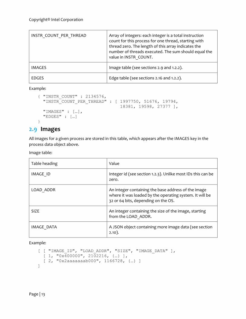
INSTR_COUNT_PER_THREAD Array of integers: each integer is a total instruction count for this process for one thread, starting with thread zero. The length of this array indicates the number of threads executed. The sum should equal the value in INSTR_COUNT.
IMAGES Image table (see sections 2.9 and 1.2.2).
EDGES Edge table (see sections 2.16 and 1.2.2).
Example:
{ "INSTR_COUNT" : 2134576,
"INSTR_COUNT_PER_THREAD" : [ 1997750, 51676, 19794,
18381, 19598, 27377 ],
"IMAGES" : […],
"EDGES" : […]
}
2.9 Images
All images for a given process are stored in this table, which appears after the IMAGES key in the
process data object above.
Image table:
Table heading Value
IMAGE_ID Integer id (see section 1.2.3). Unlike most IDs this can be zero.
LOAD_ADDR An integer containing the base address of the image where it was loaded by the operating system. It will be 32 or 64 bits, depending on the OS.
SIZE An integer containing the size of the image, starting from the LOAD_ADDR.
IMAGE_DATA A JSON object containing more image data (see section 2.10).
Example:
[ [ "IMAGE_ID", "LOAD_ADDR", "SIZE", "IMAGE_DATA" ],
[ 1, "0x400000", 2102216, {…} ],
[ 2, "0x2aaaaaaab000", 1166728, {…} ]
]

Copyright® Intel Corporation
Page | 14
2.10 Image Data
All data for a given image is stored in this object, which appears in the IMAGE_DATA column of the
IMAGES table above. The keys in the object are as follows. All are optional.
Image-object tag Value
FILE_NAME_ID Integer id from file-name table (see section 2.4).
SYMBOLS Symbol table (see sections 2.11 and 1.2.2).
SOURCE_DATA Source-data table (see sections 2.12 and 1.2.2).
BASIC_BLOCKS Basic-block table (see sections 2.13 and 1.2.2).
ROUTINES Routine table (see sections 2.14 and 1.2.2).
Example:
{ "FILE_NAME_ID" : 4,
"SYMBOLS" : […],
"SOURCE_DATA" : […],
"BASIC_BLOCKS" : […],
"ROUTINES" : […]
}
Notes:
o During the course of execution, it is possible for a dynamically-linked process to unload one
image and load another image such that the address spaces for these images overlap. In this
situation, the addresses of symbols, debug data and basic blocks are not sufficient to
uniquely identify them. Fortunately, at any given temporal point in a workload execution the
subset of active images should have non-overlapping address regions, allowing an address to
unambiguously correspond to a symbol, debug data and/or basic block. Unfortunately, if a
workload employs self-modifying-code (SMC) or any other mechanism that modifies the
code space, this might also be violated.
2.11 Symbols
All symbols for a given image are stored in this table, which appears after the SYMBOLS key in the
image data object above.
Symbol table:
Table heading Value
NAME String containing the symbol name. Special chars must be escaped per JSON specifications.

Copyright® Intel Corporation
Page | 15
ADDR_OFFSET An integer containing the base address of the symbol relative to the load address of the containing image. Thus, the actual starting address of the symbol will be the load address of the image plus this offset.
SIZE An integer containing the size of the symbol in bytes, starting from the ADDR_OFFSET.
Example:
[ [ "NAME", "ADDR_OFFSET", "SIZE " ],
[ "free", "0x127f0", 60 ],
[ "malloc", "0x12940", 13 ],
[ "calloc", "0x12a00", 9 ]
]
2.12 Source information
All debug source information for a given image is stored in this table, which appears after the
SOURCE_DATA key in the image data object above.
Source-data table:
Table heading Value
FILE_NAME_ID Integer id from file-name table (see section 2.4) representing the source-code file of this debug data.
LINE_NUM An integer representing the source-code line number from the file referenced above.
ADDR_OFFSET An integer containing the base address of the debug data relative to the load address of the containing image. Thus, the actual starting address of the data will be the load address of the image plus this offset.
SIZE An integer containing the size of the data in bytes, starting from the ADDR_OFFSET.
NUM_INSTRS An integer containing the number of instructions covered by this debug data, starting with and including the one at the starting address.
Example:
[ [ "FILE_NAME_ID", "LINE_NUM", "ADDR_OFFSET",
"SIZE", "NUM_INSTRS" ],
[ 8, 25, "0x7a8", 4, 1 ],
[ 8, 26, "0x7ac", 5, 1 ],
[ 9, 9, "0x7bb", 4, 1 ],
Copyright® Intel Corporation
Page | 16
[ 9, 10, "0x7bf", 1, 1 ],
[ 10, 11, "0x970", 43, 10 ],
[ 10, 12, "0x99b", 10, 2 ]
]
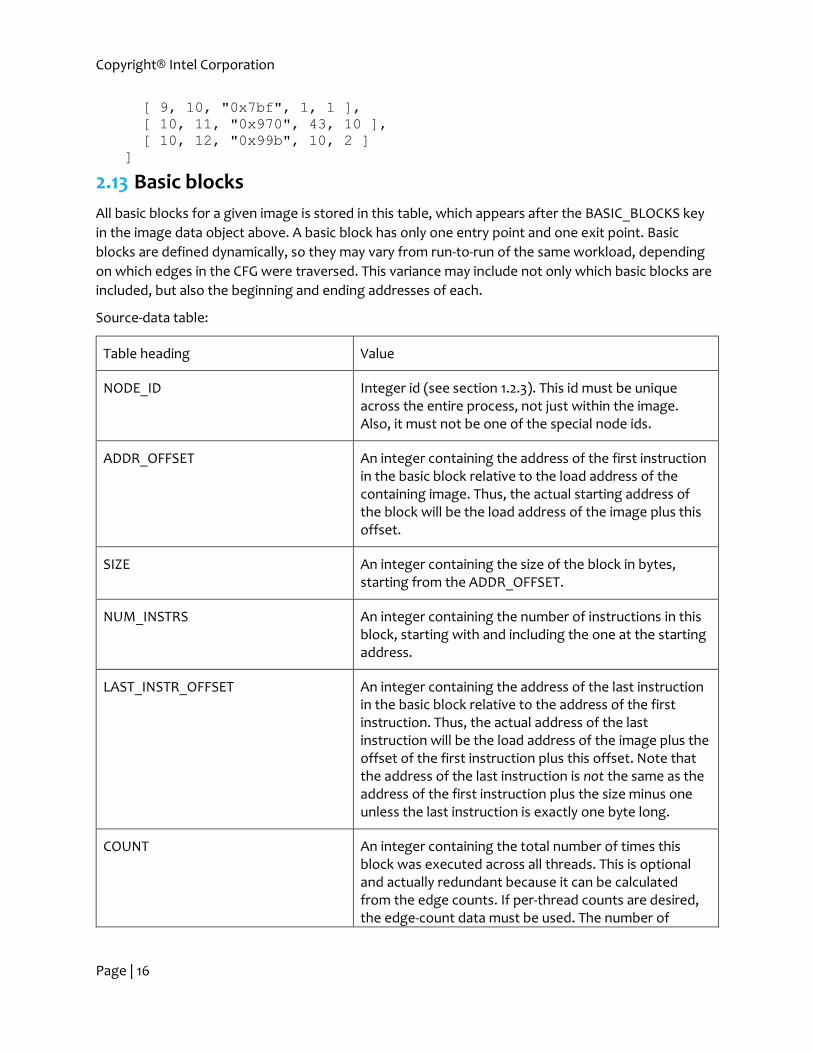
2.13 Basic blocks
All basic blocks for a given image is stored in this table, which appears after the BASIC_BLOCKS key
in the image data object above. A basic block has only one entry point and one exit point. Basic
blocks are defined dynamically, so they may vary from run-to-run of the same workload, depending
on which edges in the CFG were traversed. This variance may include not only which basic blocks are
included, but also the beginning and ending addresses of each.
Source-data table:
Table heading Value
NODE_ID Integer id (see section 1.2.3). This id must be unique across the entire process, not just within the image. Also, it must not be one of the special node ids.
ADDR_OFFSET An integer containing the address of the first instruction in the basic block relative to the load address of the containing image. Thus, the actual starting address of the block will be the load address of the image plus this offset.
SIZE An integer containing the size of the block in bytes, starting from the ADDR_OFFSET.
NUM_INSTRS An integer containing the number of instructions in this block, starting with and including the one at the starting address.
LAST_INSTR_OFFSET An integer containing the address of the last instruction in the basic block relative to the address of the first instruction. Thus, the actual address of the last instruction will be the load address of the image plus the offset of the first instruction plus this offset. Note that the address of the last instruction is not the same as the address of the first instruction plus the size minus one unless the last instruction is exactly one byte long.
COUNT An integer containing the total number of times this block was executed across all threads. This is optional and actually redundant because it can be calculated from the edge counts. If per-thread counts are desired, the edge-count data must be used. The number of

Copyright® Intel Corporation
Page | 17
instructions executed in the block is NUM_INSTRS multiplied by COUNT.
Example:
[ [ "NODE_ID", "ADDR_OFFSET", "SIZE", "NUM_INSTRS",
"LAST_INSTR_OFFSET", "COUNT" ],
[ 4, "0x7a8", 9, 2, 4, 1 ],
[ 5, "0x7b1", 5, 1, 0, 9 ],
[ 6, "0x7b6", 5, 1, 0, 8 ],
[ 7, "0x7bb", 5, 2, 4, 1 ],
[ 8, "0x7c0", 12, 2, 6, 11 ]
]
2.14 Routines
All routine information for a given image is stored in this table, which appears after the ROUTINES
key in the image data object above. Routines must follow the following rules:
o A routine can have only one entry. (A routine can have multiple exit points.)
o Each node in the routine must be reachable from the entry node. This means that each node
must be the immediate successor (target of an edge) of the entry node or another node in
the routine. Inter-routine edges (calls, returns, context changes, etc.) are not allowed in this
traversal, but bypass edges are. However, each node that is reachable from the entry node is
not required to be in the same routine; this allows for dividing routines when there are
multiple entry nodes, jumps between routines, and other non-standard control flow.
o Each node in a routine must be in the containing image.
o Every node of an image (except start and end) will appear in exactly one routine.
Thus, the addresses and sizes routines will not necessarily correspond to those in the symbol table.
Also, routines may be entered with edges other than calls and may be exited with edges other than
returns.
Routine table:
Table heading Value
ENTRY_NODE_ID Basic-block id (integer id from the basic-block table in the same image, see section 2.13) indicating the basic-block at the entry to this routine (usually a call target).
EXIT_NODE_IDS Array of basic-block ids indicating one or more basic blocks which have edges that leave this routine (these blocks usually end with return instructions).
NODES Table of all basic-block ids in this routine and their immediate dominators, including the entry and exit nodes (see below).

Copyright® Intel Corporation
Page | 18
LOOPS Loop table (see sections 2.15and 1.2.2). This can be omitted if there are no loops.
Node table:
Table heading Value
NODE_ID Basic-block id in this routine.
IDOM_NODE_ID Basic-block id of the immediate dominator of this node. This information is used in various graph algorithms.
Example:
[ [ "ENTRY_NODE_ID", "EXIT_NODE_IDS", "NODES", "LOOPS" ],
[ 4, [ 4, 5, 6, 7 ],
[ [ "NODE_ID", "IDOM_NODE_ID" ],
[ 4, 4 ],
[ 5, 4 ],
[ 6, 5 ],
[ 7, 6 ] ] ],
[ 63, [ 65, 67 ],
[ [ "NODE_ID", "IDOM_NODE_ID" ],
[ 66, 65 ],
[ 67, 63 ],
[ 63, 63 ],
[ 64, 63 ],
[ 65, 64 ] ], […]
]
2.15 Loops
All loop information for a given routine is stored in this table, which appears under the LOOPS
column in the routine table above. Loops are defined with a standard graph-traversal algorithm. The
following constraints apply:
o A loop can have only one head node.
o A loop can have multiple back-edges.
o All nodes in a loop are in the containing routine.
Loop table:
Table heading Value
LOOP_HEAD_NODE_ID Basic-block id (integer id from the basic-block table in the same image, see section 2.13) indicating the basic-block at the head of this loop.
LOOP_BACK_EDGE_SOURCE_NODE_IDS Basic-block ids of the node(s) that contain branches back to the loop head.

Copyright® Intel Corporation
Page | 19
LOOP_NODE_IDS Array of basic-block ids of all the nodes in the loop, including the head nodes, back-edge source nodes and inner loop nodes, if any.
PARENT_LOOP_HEAD_NODE_ID Basic-block id of the head node of the loop containing this loop if this is not an outer loop in this routine. This can be omitted or entered as zero (0) if it is an outer loop in this routine.
Example (loops 145 and 137 are inner loops with respect to loop 133):
[ [ "LOOP_HEAD_NODE_ID", "LOOP_BACK_EDGE_SOURCE_NODE_IDS",
"LOOP_NODE_IDS", "PARENT_LOOP_HEAD_NODE_ID" ],
[ 133, [ 139, 147 ],
[ 133, 134, 135, 136, 137, 138, 139, 145, 146, 147 ] ],
[ 145, [ 145 ], [ 145 ], 133 ],
[ 137, [ 138 ], [ 137, 138 ], 133 ]
]
2.16 Edges
All edge information for a given process is stored in this table, which appears after the EDGES tag in
the process object above. Edges are placed outside the image data because edges often go between
different images.
Loop table:
Table heading Value
EDGE_ID Integer id (see section 1.2.3).
SOURCE_NODE_ID Special node id or basic-block id of the tail of this edge (where the control flow is coming from).
TARGET_NODE_ID Special node id or basic-block id of the head of this edge (where the control flow is going to).
EDGE_TYPE_ID Edge-type integer id (see section 2.5).
COUNT_PER_THREAD Array of integers: each integer is an execution count for this edge for one thread, starting with thread zero.
Example (this process had 6 threads):
[ [ "EDGE_ID", "SOURCE_NODE_ID", "TARGET_NODE_ID",
"EDGE_TYPE_ID", "COUNT_PER_THREAD" ],
[ 4810, 1683, 3002, 16, [ 0, 0, 1, 1, 1, 0 ] ],
[ 3460, 1597, 1598, 18, [ 1, 0, 0, 0, 0, 0 ] ],
[ 953, 1597, 1599, 13, [ 7, 0, 0, 0, 0, 0 ] ]
]

Copyright® Intel Corporation
Page | 20
Notes:
Bypass-type edges may exist without their corresponding call and return edges. This will be
the case when the called code is not included in the CFG. This will always be the case for
EXCLUDED_CODE_BYPASS. In the case where there are no corresponding call and return
edges, the counts of the bypass edges should be set to indicate the number of times the call
was taken.
More typically, bypass-type edges exist with their corresponding call and return edges. This is
the normal case where the call and return are in the CFG, and the bypass edges are added to
indicate intra-routine control flow. In this case, the counts of the bypass edges should be
zero.
It is also possible to have a subset of a given call to be counted and the remainder to be
counted in its bypass, but this is uncommon.
3 DCFG-trace contents The DCFG format above contains total counts for all edges in the graph, but it does not indicate
sufficient information required to reconstruct the order in which edges, basic-blocks, routines, loops,
etc. are traversed. The purpose of the DCFG-trace format described in this section is to provide a
specification to efficiently and effectively encode the sequence of edge-ids traversed during the
execution. Given the sequence of edge-ids and the corresponding DCFG, the sequence of basic-
blocks, etc. can be reconstructed.
For the DCFG stream described in section 2, the order of entries in objects and columns and rows in
tables was not specified, and parsers should not expect or rely on any particular order. However, the
DCFG-trace is designed to be read by “streaming” parsers that make one pass from beginning to end
and do not keep all the contents in memory. For that reason, the order of contents in certain objects
and tables are specified. These will be noted in their respective sections in paragraphs labeled
“Ordering.”
3.1 Top-level structure
The top-level DCFG-trace value is an object (sequence of key-value pairs).
The major sections of the DCFG-trace stream are tagged in the top-level object. They are listed briefly
below and are expanded in the remainder of this document:
Format version.
The following data on each process:
o Process ID.
o Trace data for each thread.
Example top-level object:
{ "MAJOR_VERSION" : 1,
"MINOR_VERSION" : 0,
"PROCESSES" : […]
}

Copyright® Intel Corporation
Page | 21
Ordering: for the top-level object, all these entries must appear in this order.
3.2 Version
Identical format to that of the DCFG format (see section 2.3). A DCFG stream paired with a given
DCFG-trace stream will usually be the same version, but it is not required.
3.3 Processes
All processes are stored in this top-level tag.
Top-level tag Value
PROCESSES Process table (see below and section 1.2.2).
Process table:
Table heading Value
PROCESS_ID Integer corresponding to the actual process id (“PID”) assigned by the operating system. This should correspond to a PID in the matching DCFG, if there is one.
STRING_DICTIONARY A JSON object containing string-substitution values (see below) for this process.
TRANSITION_TABLE Edge-id transition table (see below and section 1.2.2) for this process.
THREAD_DATA A table containing more per-thread data (see section 3.4).
Example:
"PROCESSES" :
[ [ "PROCESS_ID", "STRING_DICTIONARY",
"TRANSITION_TABLE", "THREAD_DATA" ],
[ 22814, {…}, […], […] ],
[ 958, {…}, […], […] ]
]
Ordering: the columns must appear in this order. The processes (rows) can appear in any order.
3.4 String dictionary
This dictionary is used to save space by providing a look-up table for repeated edge-id sequence sub-
strings that appear in one or more following processes and threads.

Copyright® Intel Corporation
Page | 22
The dictionary is a JSON object where the keys are case-sensitive strings consisting of the characters
in the set {‘A’…’Z’, ‘a’…’z’, ‘0’…’9’, ‘+’, ‘-’}. The values are any legal edge-id
sequences (see section 3.7.1).
Example:
{ “a”: “bks2hD7kB+KDk87(6*AB)Aw3ABD9”,
“b”: “KkDk123(42*(25*a))45690D<a>7Fjdkpm”
}
3.5 Transition table
This table defines how to reconstruct a sequence of edge-ids from a bit string. It is modeled after a
standard state-transition table (see http://en.wikipedia.org/wiki/State_transition_table).
Transition table:
Table heading Value
CURRENT_EDGE_ID Integer corresponding to the ID of a given starting edge (see section 2.16) .
TRANSITION_CODE A string containing a sequence of zero or more bits, written with the characters ‘0’ and ‘1’. The maximum number of bits is 32.
NEXT_EDGE_IDS A JSON array containing one or more edge-id(s) that follow EDGE_ID.
Example:
[ [ "CURRENT_EDGE_ID", "TRANSITION_CODE", "NEXT_EDGE_IDS" ],
[ 123, "0", [ 124 ] ],
[ 123, "1", [ 125 ] ],
[ 124, "", [ 456 ] ],
[ 125, "0", [ 543 ] ],
[ 125, "10", [ 542, 549 ] ],
[ 125, "11", [ 540, 541 ] ],
…
]
Ordering: the columns must appear in this order. The data (rows) can appear in any order.
The table is used to determine the sequence of edges using a sequence of binary digits in this
manner: For any given CURRENT_EDGE_ID, the set of corresponding TRANSITION_CODEs indicate
the possible edges that can follow it. The minimum number of bits are read from the binary
sequence (described later) to unambiguously determine which NEXT_EDGE_IDS follows the
CURRENT_EDGE_ID. The last edge in NEXT_EDGE_IDS becomes the CURRENT_EDGE_ID for the
subsequent table look-up. This is repeated until the desired number of edge-ids is discovered.
This format does not prescribe the scheme used to create the encoding. It only requires that each
CURRENT _EDGE_ID + TRANSITION_CODE pair is unique. A pair is considered unique if a CURRENT

Copyright® Intel Corporation
Page | 23
_EDGE_ID and its TRANSITION_CODE expressed as a 32-bit integer padded on the right with zeros
appears only once in the table.
Not specifying the encoding scheme allows the implementation of the writing software to trade off
encoding time and complexity with encoding efficiency (compression ratio). Simple and fast but
inefficient schemes might use fixed-length bit strings and single-value edge-id sequences. More
complex and efficient schemes might use variable-length bit strings created with Huffman encoding
and similar algorithm and variable-length edge-id sequences such that common sequences are
specified with fewer bits.
Example decoding using the above example table:
Example 1: Starting at edge-id 123, with binary sequence: “110”, find the next three edge-ids. First, we
need one bit to distinguish between the two transitions from edge-id 123. The first bit is “1”, so we
consume that and find that the next edge-id is 125. There are three possible transitions from edge-id
125, but the lengths of the binary encodings are not the same: one has one bit and two have two bits.
This variable-length is typical of Huffman encoding and similar algorithms. If the next bit were “0”, it
would be a valid complete encoding. However, the next bit is “1”, which is not a valid complete
encoding, so we read the next bit, which is “0”, forming the valid encoding “10”. Therefore, the next
two edge-ids are 542 and then 549. So, the entire sequence in this example is 123, 125, 542, 549
(including the starting one).
Example 2: Starting at edge-id 123, with binary sequence: “0”, find the next two edge-ids. First, we
need one bit to distinguish between the two transitions from edge-id 123. The first (and only) bit is
“0”, so we consume that and find that the next edge-id is 124. There is only one transition from edge-
id 124, so it can be encoded with zero bits. The next edge-id must be 456. So, the entire sequence in
this example is 123, 124, 456 (including the starting one).
3.6 Thread data
Data for some or all threads of a process are stored in this table. It is not required that a DCFG-trace
contains data on all processes or all threads of a given process. For example, a trace for a 6-thread
process could contain data for threads 0 and 2 only.
Thread-data table:
Table heading Value
THREAD_ID The thread id corresponding to the following edge trace. This is not the thread-id (TID) assigned by the operating system—this is an index of threads corresponding to the entries in the INSTR_COUNT_PER_THREAD array in the process data section of the DCFG data, starting with index zero (0).
TRACE_DATA A table containing the trace data (see section 3.7).
Example:
Copyright® Intel Corporation
Page | 24
[ ["THREAD_ID", "TRACE_DATA" ],
[ 0, […] ],
[ 2, […] ],
]
Ordering: the columns must appear in this order. The threads (rows) can appear in any order.
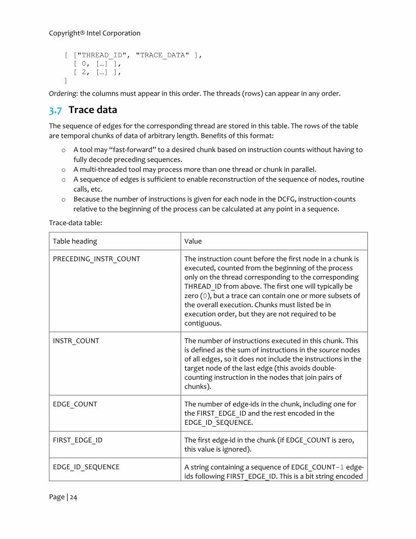
3.7 Trace data
The sequence of edges for the corresponding thread are stored in this table. The rows of the table
are temporal chunks of data of arbitrary length. Benefits of this format:
o A tool may “fast-forward” to a desired chunk based on instruction counts without having to
fully decode preceding sequences.
o A multi-threaded tool may process more than one thread or chunk in parallel.
o A sequence of edges is sufficient to enable reconstruction of the sequence of nodes, routine
calls, etc.
o Because the number of instructions is given for each node in the DCFG, instruction-counts
relative to the beginning of the process can be calculated at any point in a sequence.
Trace-data table:
Table heading Value
PRECEDING_INSTR_COUNT The instruction count before the first node in a chunk is executed, counted from the beginning of the process only on the thread corresponding to the corresponding THREAD_ID from above. The first one will typically be
zero (0), but a trace can contain one or more subsets of the overall execution. Chunks must listed be in execution order, but they are not required to be contiguous.
INSTR_COUNT The number of instructions executed in this chunk. This is defined as the sum of instructions in the source nodes of all edges, so it does not include the instructions in the target node of the last edge (this avoids double-counting instruction in the nodes that join pairs of chunks).
EDGE_COUNT The number of edge-ids in the chunk, including one for the FIRST_EDGE_ID and the rest encoded in the EDGE_ID_SEQUENCE.
FIRST_EDGE_ID The first edge-id in the chunk (if EDGE_COUNT is zero, this value is ignored).
EDGE_ID_SEQUENCE A string containing a sequence of EDGE_COUNT-1 edge-ids following FIRST_EDGE_ID. This is a bit string encoded

Copyright® Intel Corporation
Page | 25
in modified Base64 as described below (unlike the sequence in the TRANSITION_TABLE with the same name, the last edge-id encoded in this sequence is not the FIRST_EDGE_ID in the next one); see section 3.7.1.
Example:
[ ["PRECEDING_INSTR_COUNT", "INSTR_COUNT", "EDGE_COUNT",
"FIRST_EDGE_ID", "EDGE_ID_SEQUENCE" ],
[ 0, 1003408, 237298, 1,
"bks2hD7kB+KDk87(9*AB)Aw3ABD9-03n38KDFi…" ],
[ 1003408, 1483936, 386610, 842,
"Ks83bn<a>BjS920+KkDk123(2*(6*a))45690D7Fjdkpm…" ]
]
Ordering: the columns must appear in this order. The rows must appear in order of execution.
3.7.1 Converting an edge-id sequence string into a bit string
The edge-id sequence is a bit (binary digit) string. It is encoded into a sequence of ASCII characters
using modified Base64 coding. In addition, sub-sequences of characters may be further compressed
using two schemes: one for consecutive repeating sub-sequences, and one that does not require the
sub-sequences to be consecutive. Process characters from left to right. Each character determines
which of the following processing is done:
3.7.1.1 A modified Base64 character
If the character is in the set {‘A’…’Z’, ‘a’…’z’, ‘0’…’9’, ‘+’, ‘-’}, it is a modified
Base64 character as described here: http://en.wikipedia.org/wiki/Base64. We use the modified
encoding with ‘-’ instead of ‘/’ in the last position to avoid any problem with JSON libraries that
expect the slash character (solidus) to be escaped in strings. In this encoding, each character
encodes 6 bits: the values 0b000000 through 0b111111. These 64 values are mapped to the
characters in the above set in the given order; ‘A’ encodes 0b000000, ‘B’ encodes 0b000001, etc.
(Base64 encoding is 75% efficient compared to raw binary because 8 bits are used to represent 6 bits
of information.)
When the number of edge-ids indicated by EDGE_COUNT has been decoded, discard any trailing
unused bits from the last ASCII character, if any.
Example: The ASCII string “C+” encodes the twelve bits 0b000010111110. If only eleven bits were
needed, the final zero bit would be discarded.
3.7.1.2 A consecutive repeating sub-sequence
If the character is a ‘(’, there must be one or more immediately following character(s) in the set
{‘0’…’9’} followed by the character ‘*’. Read the digits and interpret them as a base-10 value, M.
Read and discard the ‘*’. Next read characters until a matching ‘)’ is reached; these characters make
up the sub-sequence. Parentheses can be nested, so a counter (or recursion, etc.) must be used to
ensure the proper characters are read. Substitute the original string, including ‘(’ and ‘)’, with M
copies of the sub-sequence. Restart processing from the beginning of the substituted value.
Examples:

Copyright® Intel Corporation
Page | 26
The ASCII string “A(4*BC)D” becomes “ABCBCBCBCD”.
The ASCII string “123(2*(6*a)b)456” becomes “123aaaaaabaaaaaab456”.
Following these substitutions, the remaining Base64 characters would be decoded into bits.
3.7.1.3 A sequence-dictionary reference
If the character is a ‘<’, read all characters following it until a ‘>’ is reached. The characters between
‘<’ and ‘>’ form a key and should appear in the STRING_DICTIONARY described in section 3.4. If the
key does not appear, this is an error. Substitute the original string, including ‘<’ and ‘>’, with the value
from the table corresponding to the key. Restart processing from the beginning of the substituted
value. Thus, values from the table can be any legal edge-id sequence string, including nested
references to other sequence-dictionary entries. Of course, circular references are not allowed. It is
also possible for consecutive repeating sub-sequences to contain sequence-dictionary references.
Examples: The STRING_DICTIONARY contains the following entries:
{ “a”: “bks2hD7kB+KDk87(6*AB)Aw3ABD9”,
“b”: “KkDk123(42*(25*a))45690D<a>7Fjdkpm”
}
The ASCII string “A<a>B” becomes “Abks2hD7kB+KDk87(6*AB)Aw3ABD9B”.
The ASCII string “(2*A<a>B)” becomes “A<a>BA<a>B” after consecutive repeating sub-sequence
substation and then
“Abks2hD7kB+KDk87(6*AB)Aw3ABD9BAbks2hD7kB+KDk87(6*AB)Aw3ABD9B” after the
two sequence-dictionary substitutions. (Equivalently, the substitution of “<a>” could be done first,
and then the remaining repeating sub-sequence could be expanded.)
The ASCII string “A<b>B” becomes “AKkDk123(42*(25*a))45690D<a>7FjdkpmB” after the
first-level substitution and then
“AKkDk123(42*(25*a))45690Dbks2hD7kB+KDk87(6*AB)Aw3ABD97FjdkpmB” after the
nested one.
Following these substitutions, the consecutive repeating sub-sequences would be expanded, and
then the remaining Base64 characters would be decoded into bits.
3.7.2 Decoding a sequence of edges
Once an edge-id sequence string is converted to a bit string as described in section 3.7.1, the entire
sequence of edge-ids for this chunk may be constructed. The first edge-id in the chunk is given in the
FIRST_EDGE_ID field. The sequence of edge-ids following this is determined by using the
TRANSITION_TABLE described in section 3.4. The data is processed from left to right until
EDGE_COUNT edge-ids have been decoded, including the FIRST_EDGE_ID.
(END OF DOCUMENT)