dynamic contact analysis and tooth modification design …
TRANSCRIPT

Int j simul model 16 (2017) 4, 742-753
ISSN 1726-4529 Original scientific paper
https://doi.org/10.2507/IJSIMM16(4)CO20 742
DYNAMIC CONTACT ANALYSIS AND TOOTH
MODIFICATION DESIGN FOR EMU TRACTION GEAR
Tang, Z. P.*; Sun, J. P.
*; Yan, L.
** & Zou, F.
***
* School of Information Engineering, East China Jiaotong University, Nanchang Jiangxi, 330013,
China ** CSR Qishuyan Locomotive & Rolling Stock Technology Research Institute Co., Ltd.,
Changzhou Jiangsu, 213011, China *** BYD Automotive Industry Co., Ltd., Shenzhen Guangdong, 230000, China
E-Mail: [email protected], [email protected], [email protected], [email protected]
Abstract
Taking traction helical gear of EMU CRH380A as an example, the meshing characteristics was
analysed. Based on Pro/E, three-dimensional helical gears were modelled. Combined with ANSYS,
the gears’ contacts were analysed under multi-condition, such as start-up, continuous and high speed.
Through transient dynamics, the distribution cloud of the equivalent stress and contact pressure in a
meshing period are solved, which at different meshing position under different condition. And the
contact state, the stress changes and distribution regularity in the meshing process were analysed. Then
on the basis of the results, gear modification parameters were designed, and the modification gears
finite element model were constructed. To compare gear contact stress distribution before and after
being modified, it shows that the modification scheme can effectively reduce the gear meshing impact
and the transmission noise. (Received, processed and accepted by the Chinese Representative Office.)
Key Words: EMU (Electric Multiple Units) Traction Helical Gear, Traction under Multi-
Condition, Finite Element Model, Dynamic Contact Analysis, Modification Design
1. INTRODUCTION
With the continuous development of China's rail transport, EMU has become an important
and modern symbol of railway science and technology. Speed is the eternal pursuit of
transport. Noise is the overriding factor in limiting the speed [1]. Researches showed that the
person’s hearing may suffer serious damage that stays in the environment above 80 dB (A)
noise for a long time. Nowadays, in the European and Japanese, noise has been important
indicators to evaluate the comfort of high speed train. According to the Prof. Zhou and others’
researches [2], if a train will travel at the speed of 350-400 km/h, noises of sightseeing area
will reach to 93-98 dB (A), and the noise will increase linearly with the increase of speed.
The noise source of EMU is mainly composed of wheel-rail noise, structure-borne noise,
the noise of traction motor, the electromagnetic noise of Electric-Current Collecting System,
aerodynamic noise and so on. According to the high-speed EMU noise tested by Zhang et al.
[3], it shows that the middle and low frequency noise is more obvious than the high frequency
noise; the frequency band is mainly around 10-1000 Hz. For the test of dynamic noise and
vibration from the locomotive traction gear transmission system, Li [4] found that the peak
noise frequency of the traction gear transmission is mainly concentrated in the low frequency
about 450-1300 Hz, and became one of the main noise sources of the vehicle. The essence of
high speed EMU traction gear transmission system is both Multi-DOF and nonlinear with
time-varying parameters and the clearance, its structure-borne noise is mainly caused by the
dynamic response from the internal and external excitation as the large and small gear
meshing. As the speed increases, the impulsive noise will increase significantly, and it will
lead some different breakdowns and damages, such as pitting, tooth root bending fatigue,
break and so on, so the study of contact stress of traction gear is very meaningful.
Tang, Sun, Yan, Zou: Dynamic Contact Analysis and Tooth Modification Design for EMU …
743
On the basis of the energy conservation law, Bajer and Demkowicz [5] established a rigid
body contact finite element model for gear system and studied dynamic contact impact
problems of galaxies gear system as meshing. Using the finite element principle combined
with the contact mechanics theory, Parker et al. [6] studied the gear pair nonlinear dynamic
response considering the time-varying stiffness and tooth clearance. Wu et al. [7] established
the finite element model of meshing gear pair and explored continuous dynamic
characteristics in elastic meshing process at the low-speed and high-speed. Taking the
domestic high-speed train at the speed above 300 km/h as the research object, Zhong et al. [8]
established the classical dynamic model and the time-varying characteristic model on gear
pair meshing stiffness, and simulated dynamically the transmission system under the driving
condition. Hu et al. [9] used finite element software and display dynamic analysis method to
explore dynamic meshing characteristics of helical gear pair with different displacement
coefficient and helix angle parameters.
Traction drive system is the power source core of running parts of high-speed EMU. It
was right under the passenger compartment. The vibration noise generated by the alternating
meshing of the gear under high-speed operation not only reduces the performance of the
gearing system but also reduce the passenger comfort. What is more, it even endangers the
safety of train operation [10]. Therefore, it is necessary to further study the stability of
traction gear drive and noise reduction technology. According to the gear noise theory, gear
modification is a common measure to improve transmission performance [11], reduce
vibration and noise. Reasonable tooth shape can effectively reduce the shock vibration and
dynamic load of gear tooth, reduce vibration and noise caused by internal excitation, achieve
uniform tooth surface load and improve transmission performance.
Park et al. [12] measured the teeth modification and meshing line tilt amount as design
variables, evaluated the dynamic meshing force fluctuation between the planetary gears,
assessed the stress distribution uniformity, and optimized the planetary gear modification
parameters for wind turbine gearbox. Huang [13] built a modification gear model for EMU
and studied the influence of three modification parts & elements on tooth contact by the finite
element dynamic simulating method. He came to a conclusion that the quadratic and sine
curve effect is good for contact as meshed into and out. Kognole [14] proposed a method to
calculate the modification parameters based on working condition. He applied contact spot or
root strain gauge method, calculated the tooth load, surface contact and root bending stress
through the finite element program as the gear with machining error and assembly error. And
then he modified the gear according to the calculation results. Zhu et al. [15] established a
dynamic contact finite element model for megawatt wind turbine gearbox. By using ANSYS /
LS-DYNA explicit dynamic method, he determined the curves and parameters by calculating
the amount of modification. Yang et al. [16] determined the best modification parameters by
analysing the relationship among the modification parameters, transmission error and contact
stress.
Gear modification methods and parameters should be based on specific structural
parameters, actual traction conditions and meshing characteristics. From the existing
literature, lots of scholars’ studies are limited in a specific condition [17, 18], and current
high-speed EMU traction gear modification parameters are based on the continuous traction
condition, which is different from the actual multi-condition, as well as ignores the impact of
other traction conditions such as start-up, high-speed, braking and so on. In the design and test
of planetary gear system in transmission differential of open-rotor engine, by finite element
analysis and tooth contact analysis, Imai et al. [19] found that the optimal modification value,
the length, and the curve of modification are different under different working conditions. In
this paper, taking G301 traction helical gear of EMU CRH380A as an example, the dynamic
contact under multiple operating conditions was analysed by the transient dynamic method,
Tang, Sun, Yan, Zou: Dynamic Contact Analysis and Tooth Modification Design for EMU …
744
the ANSYS analysis and Pro/E model. According to the results, the three parts and elements
of gear modification are calculated and designed, and the modification effect is compared.
2. TRACTION CONDITIONS AND CHARACTERISTICS OF CRH380A
CRH380A continuous operation speed is 350 km/h, the maximum operating speed is 380
km/h, and it is one of the mainstream models of China's high-speed EMU. For traction helical
gear G301, its helix angle is 26° and its normal pressure angle is 26°. According to the theory
of gear transmission, when the helix angle is more than 16°, there will be large axial force to
cause a larger temperature rise. With the pressure angle increasing, the normal pressure of the
tooth surface increases. Thereby the gear pitches line impact and mesh momentum increases.
Especially when gear works at high-speed, the non-linear shock and vibration noise will be
amplified, due to the gear transmission error, wheel and wheel body elastic deformation as
well as thermal deformation. Only through the precise modification design, it can satisfy the
requirements of high precision and high performance transmission for high-speed EMU.
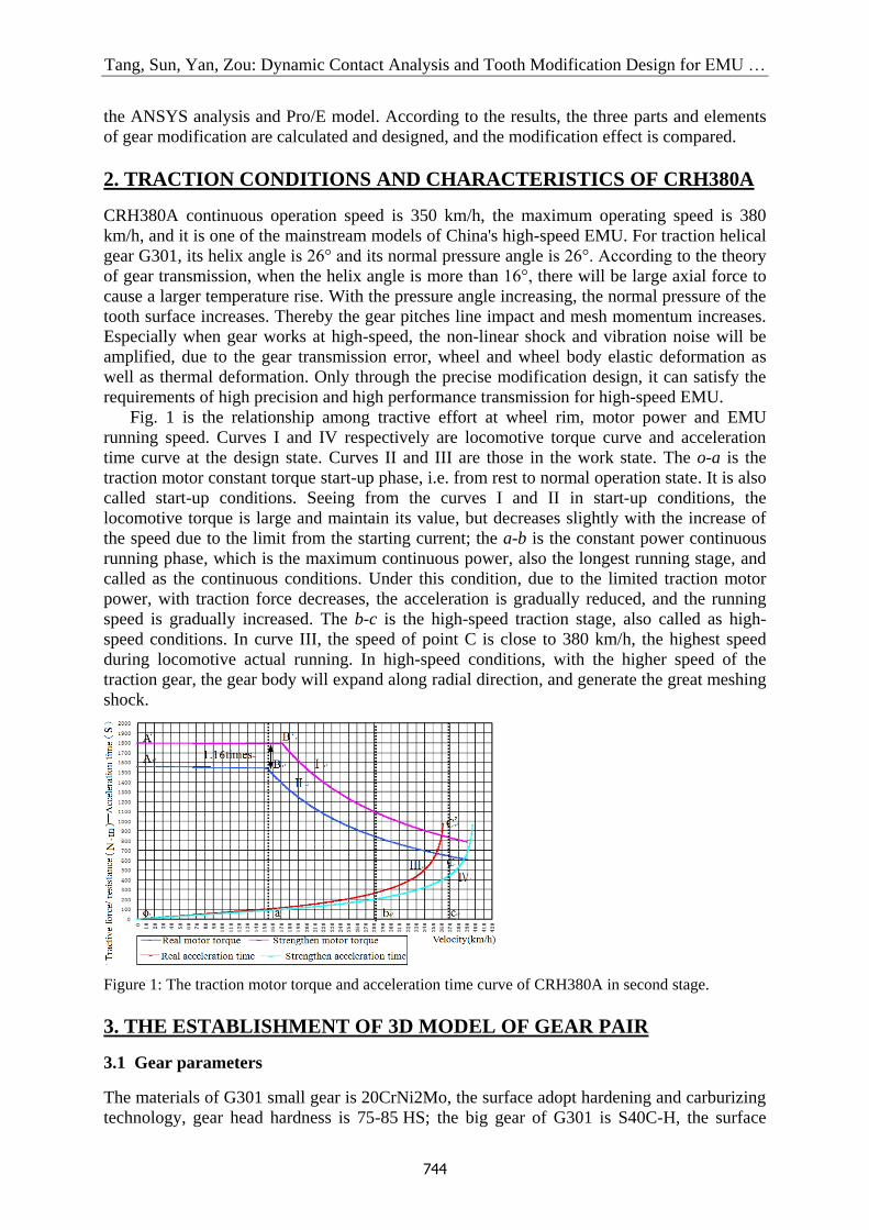
Fig. 1 is the relationship among tractive effort at wheel rim, motor power and EMU
running speed. Curves I and IV respectively are locomotive torque curve and acceleration
time curve at the design state. Curves II and III are those in the work state. The o-a is the
traction motor constant torque start-up phase, i.e. from rest to normal operation state. It is also
called start-up conditions. Seeing from the curves I and II in start-up conditions, the
locomotive torque is large and maintain its value, but decreases slightly with the increase of
the speed due to the limit from the starting current; the a-b is the constant power continuous
running phase, which is the maximum continuous power, also the longest running stage, and
called as the continuous conditions. Under this condition, due to the limited traction motor
power, with traction force decreases, the acceleration is gradually reduced, and the running
speed is gradually increased. The b-c is the high-speed traction stage, also called as high-
speed conditions. In curve III, the speed of point C is close to 380 km/h, the highest speed
during locomotive actual running. In high-speed conditions, with the higher speed of the
traction gear, the gear body will expand along radial direction, and generate the great meshing
shock.
Figure 1: The traction motor torque and acceleration time curve of CRH380A in second stage.
3. THE ESTABLISHMENT OF 3D MODEL OF GEAR PAIR
3.1 Gear parameters
The materials of G301 small gear is 20CrNi2Mo, the surface adopt hardening and carburizing
technology, gear head hardness is 75-85 HS; the big gear of G301 is S40C-H, the surface
Tang, Sun, Yan, Zou: Dynamic Contact Analysis and Tooth Modification Design for EMU …
745
adopt high frequency quenching technology, gear head hardness is 65-75 HS, the root
hardness is over 60 HS. The modulus of the gear pair is smaller than that of ordinary high
speed and heavy duty locomotive gears, and the helix angle and the normal pressure angle are
relatively big compared to that of ordinary. The main parameters are shown in Table I.
Table I: Gear parameter table.
Name Driving gear Driven gear
Teeth z 29 69
Modulus mn (mm) 7
Normal pressure angle n () 26
Helix angle () 20
Tooth face width B (mm) 70
The coefficient of addendum ha* 1
The coefficient of tip gap c* 0.25
Modification coefficient Xn 0 -0.284588
3.2 The geometric parameters of gear tooth
In Pro/E, using the default reference coordinate system draft four datum curves of gear pitch
circle, base circle, addendum circle and root circle (their diameters are respectively expressed
as d, db, da, df ). In order to realize parameterized modelling, the gear geometry parameter
constraint equations are added in the editor dialog box, as shown in Table II.
Table II: Gear reference circles relationship.
The geometry constraint equations of four reference circles
/ cosnd m Z cosb tdd
*
a a n nh h X m
2a ad hd
* *
f a n nh h c X m
2f fd d h
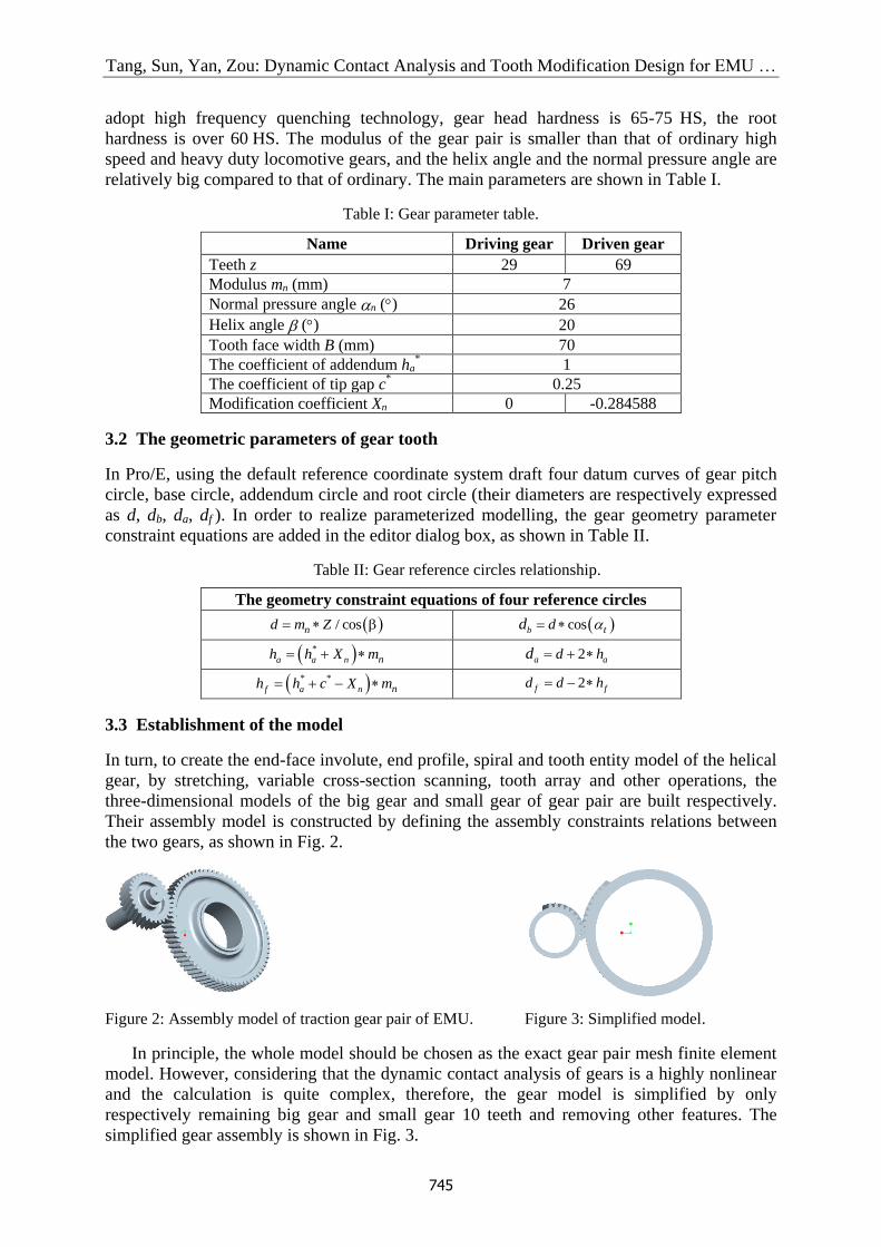
3.3 Establishment of the model
In turn, to create the end-face involute, end profile, spiral and tooth entity model of the helical
gear, by stretching, variable cross-section scanning, tooth array and other operations, the
three-dimensional models of the big gear and small gear of gear pair are built respectively.
Their assembly model is constructed by defining the assembly constraints relations between
the two gears, as shown in Fig. 2.
Figure 2: Assembly model of traction gear pair of EMU. Figure 3: Simplified model.
In principle, the whole model should be chosen as the exact gear pair mesh finite element
model. However, considering that the dynamic contact analysis of gears is a highly nonlinear
and the calculation is quite complex, therefore, the gear model is simplified by only
respectively remaining big gear and small gear 10 teeth and removing other features. The
simplified gear assembly is shown in Fig. 3.

Tang, Sun, Yan, Zou: Dynamic Contact Analysis and Tooth Modification Design for EMU …
746
4. DYNAMIC CONTACT ANALYSIS OF GEAR PAIR
There were many achievements in the study of contact stress and contact strain of gear
meshing by using finite element method. However, most of them used static contact analysis
of two-dimension or three-dimension. And though the static contact analysis can get the
contact stress of gear meshing by many times solving, yet it can’t accurately reflect the actual
gear contact state. In this paper, dynamic contact analysis of traction gear pairs is carried out
by means of transient dynamic analysis.
4.1 The transient dynamic analysis
Transient dynamics is a technology to research the structure dynamic response process under
the load with arbitrary changes over time. It is a kind of time domain analysis. The input data
is the load on the value as a function of time, and the output data is the displacement, strain
and stress, etc. The basic equation of the transient dynamic is:
( )M x C x K x F t (12)
In Eq. (1), [M] is the mass, [C] is the damping, and [K] is the stiffness matrix; {x} is the
displacement, {F(t)} is the force, {x'} is the velocity, and {x''} is the acceleration vector. For
any fixed time (t), Eq. (1) can be regarded as a static equation considering both damping force
[C]{x'} and inertial force [M]{x''}. For the equations at different time points, the time
increment t between two arbitrary adjacent time points t1 and t2 is called integral time step.
In ANSYS workbench, it can be solved by using the Newmark time integral method.
4.2 Three-dimensional meshing model of gear pair
Define the gear material properties
CRH380A EMU traction helical gear material parameters are listed in Table III.
Table III: The Parameters of gear material.
Elastic modulus E (MPa) Poisson's ratio Density (kg/m3)
The large gear 112.0 10 0.29 7800
The small gear 112.06 10 0.31 7850
In the ANSYS Workbench, to select "Analysis Systems" in the toolbox and click on
"Transient Structural", to define the finite element analysis system as the transient dynamics
system, double-click the sub-module “Engineering Data” in the transient dynamics analysis
system, then the material properties window is pop-up. To select the "Structural Steel" option
on the "Outline of Schematic A2: Engineering Date", change it to "gear1", the material
properties of "gear1" can be filled in. Similarly, the material properties of "gear2" are set.
Build a finite element model
In the ANSYS Workbench, to right-click "Transient Structural", and choose "Import Model"
→ "Browse", from the folder, select the traction helical gear assembly model file which
created by Pro/E before. To select the "Model" option in the transient dynamics analysis
system, the system can be entered.
The two sides of the large and small gears are selected and respectively named as "C2",
"C1". This step is mainly to facilitate the choice of contact surface and target surface after the
contact pair is established between the two gears. The contact surface is generally to choose
the surface being a relatively soft tooth. In this paper, it is manually modified that the target
surface of contact pair as the tooth surface of the driving gear (small gear), and the contact

Tang, Sun, Yan, Zou: Dynamic Contact Analysis and Tooth Modification Design for EMU …
747
surface as the large gear tooth surface. To select the contact type for friction, the friction
coefficient is filled in 0.1.
Finite element mesh division
Meshing has obvious influence on the calculation results; there are a few points to note. First
of all, it is the number of meshes. The number of meshes can be determined by comparing the
results of the meshing calculation. When the number of meshes does not significantly affect
the analysis results, it is not necessary to continue to increase the number of meshes. Secondly,
it is the mesh density. Depending on the influence of the calculation results, different sizes of
meshes can be divided into different positions. In this article, the gear contact stress is mainly
analyses. The meshes of the gear teeth should be denser with smaller meshes, and larger
meshes in other areas. Thirdly, it’s the quality of the mesh. In ANSYS Workbench, the
automatic mesh can make analysis model to generate a suitable meshes, considering the
number of meshes and meshes density impact on the calculation results, it is necessary to
refine the meshes in the place of teeth meshing where stress is concentrated (Fig. 4).
Figure 4: Mesh refinement results.
4.3 Finite element solution
Due to the basic consistency of the transient dynamic solution in the start-up, continuous and
high speed working conditions. In this paper, the dynamic contact analysis process is
introduced under the start-up condition as an example.
Impose constraints
As the analysis of dynamic contact stress of the helical gear pair, both the big gear and small
gear must have degree of freedom of rotation around self-axis. In order to simplify the model,
the redundant degrees of freedom can be constrained.
Set the time steps
The choice of time step should be appropriate, too long or too short will affect the simulation
time and the accuracy of the results. To click "Analysis Settings", then in the detail window
"Step End Time", "Initial Time Step", "Minimum Time Step" and "Maximum Time Step" are
respectively set as "0.004", "0.0002", "0.0002" and "0.0003", and other remain the default.
Define the load
A rotational speed is applied to the driving gear (pinion gear), and a torque is applied to the
driven gear (large gear). The rotational speed and torque applied under the three working
conditions are shown in Table IV.
Table IV: Gear speed and torque in three working conditions.
Start-up Continuous High speed
Torque (N.m) 1900 841.5 569.5
Rotate (rad/s) 31 434 641

Tang, Sun, Yan, Zou: Dynamic Contact Analysis and Tooth Modification Design for EMU …
748
Define the speed
The following operations are done: right-click on the "Transient", add "To be Load", select
the previously created revolute pair of pinion gear, namely "Revolute - Ground To Gear1",
"Type" to "rotation", set speed value in the table data. In order to guarantee the convergence,
the rotational speed is changed from 0 to 31 rad/s at a time step.
Define the resistance torque
As above, add the hinge, select the previously created pinion rotation pair, "Revolute-Ground
to Gear2", then set the "Hinge type" to "Moment" and the torque value to "1900".
Define the solution content
Equivalent stress and contact stress need to be analysed. The following operations are done:
in turn to right-click "Solution", "Solution", "Contact Tool", and "Solution", and select
"Equivalent", "Contact Tool", "Pressure" and "Solve". Then the Solution can be waiting for.
4.4 Solution results analysis
The Mises stress nephogram (Fig. 5) shows that the equivalent stress pattern of the gear pair
at one moment under the start-up condition. It can be seen that in the moment of contact gear,
the equivalent stress is the largest. The stress gradually spreads to gear wheel body, and the
stress at roots of the tooth is larger. And the conclusion is similar in the other two conditions.
Figure 5: Mises stress nephogram of gear contact in start-up condition.
Fig. 6 is also a cloud diagram, which shows the contact stress of the helical gear pair at
different meshing positions in same engagement cycle under the start-up conditions. Among
them, Figs. 6 b and e show respectively the contact pressure contours at the position of mating
teeth coming into or out of contact. Figs. 6 a, c, e and f are the contact pressure contours at the
position of normal meshing position of helical gear pair.
a) b) c)
d) e) f)
Figure 6: Contact pressure pattern of gear pair at different meshing positions under start-up conditions.

Tang, Sun, Yan, Zou: Dynamic Contact Analysis and Tooth Modification Design for EMU …
749
Similarly, contact pressure cloud diagram can be solved for other conditions, the contact
stress data of the meshing position of gear pair in the three working conditions are listed in
Table V.
Table V: The maximum contact stress at different meshing positions and working conditions.
Fig. 6 a
(MPa)
Fig. 6 b
(MPa)
Fig. 6 c
(MPa)
Fig. 6 d
(MPa)
Fig. 6 e
(MPa)
Fig. 6 f
(MPa))
Meshing positions meshing
mesh into meshing
meshing
mesh out meshing
Start-up 1111.4 2543.8 1790.2 1885.6 2322.6 1312.4
Continuous 1180.2 3616.4 1918.5 1320.9 3469.9 1620.1
High-speed 2147.9 4771.7 3561.2 2060.5 4559.4 2128.1
Through analysing the solution, we can get the following conclusions:
(1) The contact path of the helical gear pair during meshing is an approximate oblique line
along the tooth surface, and the contact stress is non-uniformly distributed along the contact
line. The number of meshing teeth is more than or equal to 2 under the three working
conditions. It shows that the meshing coincidence degree of the traction helical gear in EMU
CRH380A is more than 2, which is the same as the theory of helical gear transmission
characteristics, and verifies the reliability of the simulation results.
(2) Comparing the maximum contact stress of gear pair in the three working conditions,
with the increase of rotational speed, the maximum contact stress of the gear pair gradually
increases, and the contact stress of the gear pair under high speed condition is the highest. The
reason is that with the increase of speed, the gear pair will not only produce greater contact
pressure, gear teeth also produce greater heat friction, the gears have a certain deformation, so
as to the gear contact pressure increases.
(3) Under the three conditions, the maximum contact stress is higher in the positions of
meshing into and out than that of the other meshing position under the same condition, and
the contact stress of meshing into is the maximum in all positions. As meshing into and out,
the tooth is subjected to a large elastic deformation, and the gears can't mesh properly.
Therefore it produces too much meshing impact, makes a sharp rise in the contact stress, and
meshes into impact effect on the contact stress is larger than the effect of meshes out.
5. DESIGN OF GEAR MODIFICATION PARAMETERS
In view of the above dynamic contact analysis, considering that tooth profile modification can
reduce the impact vibration and dynamic load of tooth, and the tooth root modification is easy
to reduce the bending strength of the gear which threaten EMU traffic safety, so only large
and small gear modify their teeth top. The modification parameters was precisely designed for
them by combining with the three parts and elements of gear modification, such as the amount
of tooth profile modification, modification curve and the length of modification.
5.1 Gear profile modification
Gear meshing impact is result of the gear deformation making the actual base section is not
equal to the actual base section for the driving gear. Therefore, the theoretical modification
should be equal to the maximum deformation of the gear at the meshing moment. From the
gear contact stress analysis, in the high-speed condition, the contact stress of the gear meshing
is the largest. Therefore, the maximum deformation amount of the gear in the high-speed
working condition is used as the modification amount. The work of the driving gear is divided
into two parts: one part is the drive driven gear movement, the other part is the power
consumption in the gear clearance impact. In order to avoid inaccurate result of the clearance

Tang, Sun, Yan, Zou: Dynamic Contact Analysis and Tooth Modification Design for EMU …
750
error, when solving the pinion addendum deformation, the pinion is fully constrained and
torque is applied to the large gear. On the contrary, for large gear modification amount, the
big gear is fixed, and torque is applied to the pinion (Fig. 7). According to the meshing
principle, in the Pro/E software, the gear pair is adjusted to the pinion just in the engaged
position. The model was imported into the Workbench for calculation (Fig. 8). The maximum
deformation of the pinion gear surface was 0.02 mm. So the modification of the pinion was
0.02 mm. By the same logic, the amount of tooth top modification for big gear was 0.023 mm.
Figure 7: Set the gear load
and constraints.
Figure 8: Tooth surface
deformation of pinion.
Figure 9: Meshing line diagram.
5.2 The length of the modification
Gear modification has two types: long and short, due to the relatively large degree of overlap,
helical gears usually choose long-shaped modification. Fig. 9 is a graph of the meshing of the
two gears on the end face. When the gear is driving, contact point is for the continuous
movement in the meshing line. The gear meshing starts at point SAP and stops at the EAP
point. The single pair teeth mesh interval is from HPSTC to LPSTC, double pairs teeth mesh
intervals are from EAP to HPSTC and from LPSTC to SAP.
From the gear parameters and Fig. 9, the following equation is obtained:
2 2
1 6 2 2a bC C r r (2)
2 5 btC C P (3)
3 1 tanb wtC r (4)
4 1 btC C p (5)
2 2
5 1 1a bC r r (6)
6 1 2(r r ) tanb b wtC (7)
5 1 r btC C p (8)
The specific meanings of the parameters are as follow. Pbt: the pitch of the base circle end
face; r: the contact ratio of helical gears; wt: the meshing angle of the end surface; rb1 and
rb2: radius of base circle; C6: theoretical meshing length; C5: the exit meshing point length;
C1: the length from entering the meshing point; C5 – C1: the actual length of meshing line; ra1
and ra2: radius of addendum circle.
5.3 The modification curve design
The tooth profile modification types include straight line modification and curve
modification. When the curve is modified, the modification curve is tangent to tooth profile
involute, and the modification force of the modified tooth changes a little, and the
modification effect is good. Power function modification curve can be expressed as:
max ( )bx
l (9)

Tang, Sun, Yan, Zou: Dynamic Contact Analysis and Tooth Modification Design for EMU …
751
In the equation, l is the length of the modification, x is the tooth meshing position, Δ is
the amount of modification corresponding the mesh position, b value is usually in the range
from 1.0 to 2.0. When b equals 2, the modification curve is parabola which relatively smooth
with the profile transition, and the meshing impact is small. In this paper, parabola shape
modification is used.
6. THE ESTABLISHMENT OF MODIFIED HELICAL GEAR MODEL
6.1 Create the modification curve
Pbt = 20.771 mm. For Eqs. (2) to (8), to substitute the relevant parameters of the gear into
them, the equations for the radius of addendum modification initial circle can be obtained for
the driving gear and the driven gear, as shown in Eqs. (10) and (11).
2 2
4 b11= +rtr C (10)
2 2 2
6 2 b12= -C +rtr C( ) (11)
It is calculated that the radius of the initial circle for the driving gear is 110.77 mm and the
radius of the initial circle for the driven gear is 259.68 mm. Taking the following pinion as an
example, in the Pro/E curve fitting modification, the specific process is as follows:
Create a modification terminal point
As the maximum tooth tip modification is the distance from modification terminal point to the
profile end point on gear end face. Taking the profile end point on gear end face as a
reference, the maximum modification amount is offset to create datum point.
Create a modification starting point
The starting point of the modification is the intersection point between the initial circle of the
gear modification and the involute of the tooth profile. So the initial circle should be firstly
sketched. The datum point is established at the intersection point between the involute of the
gear tooth profile and the initial circle of the modification.
Create a modified coordinate system
In order to ensure that the modification curve and the tooth profile transition are relatively
smooth, the modification curve should be tangent to the tooth profile involute line at the
beginning of the modification. Therefore, the coordinate system created at the beginning of
the modification should also be tangent to the involute profile. The process is as follows. To
create a datum plane BTM14 which is via the starting point and perpendicular to the involute;
to create a datum plane BTM on the end face of the tooth profile, and create a datum BTM16
which is perpendicular to the datum planes BTM15 and BTM14 as well as passes the datum
point PNT5, so the coordinate system CS5 is created with BTM14, BTM15, BTM16.
Create a modification curve
To create curve by clicking on the "Curve" button and select "From equation", then select the
coordinate system CS5 and "Cartesian" type, input the following Eqs. (12) to (14) for the
pinion or Eqs. (15) to (17) for large gear. The build curves are shown in Figs. 10 and 11.
Figure 10: The pinion modification
curve.
Figure 11: Large gear
modification curve.
Figure 12: The two modified
gear model.

Tang, Sun, Yan, Zou: Dynamic Contact Analysis and Tooth Modification Design for EMU …
752
The pinion modification curve equation:
5.2*x t (12) 2
0.118*(5.2* / 3.5)y t (13)
0z (14)
Large gear modification curve equation: 5.2x t (15)
20.213 (5.2 / 3)y t (16)
0z (17)
6.2 Create a modified gear model
To take those modified curves as reference sketches, create modification surface and tooth.
By rotating and array the tooth, modify all gear teeth of helical gear, the modified helical gear
model can be gotten, shown as in Fig. 12.
7. ANALYSIS AND COMPARISON OF MODIFICATION EFFECT
The specific operation steps of the modified gear finite element analysis are the similar as
before modification, only need to replace the unmodified gear model with modified gear
model, so the details don’t display. The equivalent contact stress distribution of the gear tooth
under each working condition is shown in Table VI.
Table VI: The maximum stress in the different meshing positions and working conditions.
Fig. 6 a
(MPa)
Fig. 6 b
(MPa)
Fig. 6 c
(MPa)
Fig. 6 d
(MPa)
Fig. 6 e
(MPa)
Fig. 6 f
(MPa)
Meshing positions meshing mesh into meshing meshing mesh out meshing
Start-up 990.86 2226.2 1987.7 1693.9 2062.9 1197.4
Continuous 1722 3001.9 2135.4 1061.5 2958.8 1503.9
High-speed 1813.8 3878.3 2920.6 2352.4 3743.5 1625.7
Comparing Table V and Table VI, the following conclusions can be drawn:
The maximum contact stress of the gear mesh into and mesh out is reduced. The
maximum contact stresses as the gear mesh into are respectively decreased by 12.49 %,
16.99 % and 18.72 % under start-up, continuous and high-speed working conditions. The
maximum contact stress as the gear mesh out are respectively are decreased by 12.49 %,
16.99 % and 18.72 % under the three working conditions. By optimizing the three parts and
elements of gear modification, the maximum contact stress of the gears is reduced and the
meshing impact is decreased and the gear transmission performance is improved.
In this paper, the traction helical gear pair of high-speed EMU CRH380A is taken as the
research object, and the dynamic contact analysis of the traction helical gear pair under the
three conditions of start-up, continuous and high-speed is carried out by ANSYS Workbench.
According to the results of the solution, the gears were modified by the three parts and elements
of tooth profile design, the dynamic contact analysis of the modified gear pair was done
again, compared the maximum contact stress of the gear pair before and after modification,
the gear contact state is effectively improved, which reduces the impact of the gear in running
process and provides the theoretical basis for the practical modification design of gears.
ACKNOWLEDGEMENT
This project is supported by National Natural Science Foundation of China (Grant No. 51765015, No.
51465017) and supported by the Natural Science Foundation Project of Jiangxi Province
(20171BAB206027).

Tang, Sun, Yan, Zou: Dynamic Contact Analysis and Tooth Modification Design for EMU …
753
REFERENCES
[1] Lee, P. J.; Griffin, M. J. (2013). Combined effect of noise and vibration produced by high-speed
trains on annoyance in buildings, The Journal of the Acoustical Society of America, Vol. 133, No.
4, 2126-2135, doi:10.1121/1.4793271
[2] Zhang, J.; Xiao, X.-B.; Wang, D.; Zhou, Z.-R.; Jin, X.-S. (2012). Characteristics and evaluation
of noises in the tourist cabin of a train running at more than 350 km/h, Journal of the China
Railway Society, Vol. 34, No. 10, 23-29
[3] Zhang, J.; Xiao, X.-B.; Zhang, Y.-M.; Li, Z.-H.; Zhang, C.-Y.; Jin, X.-S. (2015). Study on
transfer path characteristic of interior noise of 100 % low-floor railway train, Journal of Vibration
Engineering, Vol. 28, No. 4, 541-549
[4] Li, S. (2011). The Noise and Vibration Characteristic Analysis of the Traction Motor Drive
System, Dalian Jiaotong University
[5] Bajer, A.; Demkowicz, L. (2002). Dynamic contact/impact problems, energy conservation, and
planetary gear trains, Computer Methods in Applied Mechanics and Engineering, Vol. 191, No.
37-38, 4159-4191, doi:10.1016/S0045-7825(02)00359-6
[6] Parker, R. G.; Vijayakar, S. M.; Imajo, T. (2000). Non-linear dynamic response of a spur gear
pair: modelling and experiential comparison, Journal of Sound and Vibration, Vol. 237, No. 3,
435-455, doi:10.1006/jsvi.2000.3067
[7] Wu, Y.-J.; Liang, Y.; Yang, Y.; Wang, J.-J. (2012). Dynamic meshing characteristics of a gear
pair using contact finite element method, Journal of Vibration and Shock, Vol. 31, No. 19, 61-67
[8] Zong, L.-X.; Li, X.-L.; Ma, W.-H.; Liu, W. (2014). Analysis of drivetrain modelling and dynamic
for EMU, Machinery Design & Manufacture, Vol. 21, No. 9, 95-98
[9] Hu, Y.-M.; Shao, Y.-M.; Chen, Z.-G.; Zuo, M. J. (2011). Transient meshing performance of
gears with different modification coefficients and helical angles using explicit dynamic FEA,
Mechanical Systems and Signal Processing, Vol. 25, No. 5, 1786-1802, doi:10.1016/
j.ymssp.2010.12.004
[10] Hwang, H.-Y.; Chen, J.-S. (2011). Noise and vibration on the bogie of a mass rapid train, Journal
of Mechanical Science and Technology, Vol. 25, No. 10, 2519-2528, doi:10.1007/s12206-011-
0732-1
[11] Eritenel, T.; Parker, R. G. (2012). Three-dimensional nonlinear vibration of gear pairs, Journal of
Sound and Vibration, Vol. 331, No. 15, 3628-3648, doi:10.1016/j.jsv.2012.03.019
[12] Park, Y.-J.; Kim, J.-G.; Lee, G.-H.; Shim, S. B. (2015). Load sharing and distributed on the gear
flank of wind turbine planetary gearbox, Journal of Mechanical Science and Technology, Vol. 29,
No. 1, 309-316, doi:10.1007/s12206-014-1237-5
[13] Huang, Q. (2012). Research on Tooth Profile Modification and the Optimization Design for Gear
Box of High-speed Train Drive System, Dalian University of Technology
[14] Kognole, S. (2014). Optimizing the geometric parameters of new gear pair using existing gear
pairs, SAE Technical Paper 2014-01-1770, doi:10.4271/2014-01-1770
[15] Zhu, C.-C.; Chen, S.; Ma, F.; Xu, X.-Y.; Xu, L.; Zhang, X. (2013). Effect of gear teeth
modification on dynamic characteristics of a megawatt level wind turbine gearbox, Journal of
Vibration and Shock, Vol. 32, No. 7, 123-128
[16] Yang, B.-Y.; Chu, C.-M; Tang, H.-C.; Miao, G. (2012). Research on gear modification
parameters affecting transmission performance, Journal of Mechanical Transmission, Vol. 36,
No. 9, 8-11
[17] Zhang, H. P. (2015). An agent-based simulation model for supply chain collaborative
technological innovation diffusion, International Journal of Simulation Modelling, Vol. 14, No. 2,
314-324, doi:10.2507/IJSIMM14(2)CO6
[18] Jiang, S. B.; Zhang, X.; Gao, K. D.; Gao, J.; Wang, Q. Y.; Hidenori, K. (2017). Multi-body
dynamics and vibration analysis of chain assembly in armoured face conveyor, International
Journal of Simulation Modelling, Vol. 16, No. 3, 458-470, doi:10.2507/IJSIMM16(3)8.391
[19] Imai, H.; Goi, T.; Kijima, K.; Nishida, T.; Arisawa, H.; Matsuoka, T.; Sato, M. (2013). Design
and test of differential planetary gear system for open rotor power gearbox, Proceedings of the
ASME 2013 Power Transmission and Gearing Conference, 10 pages, doi:10.1115/DETC2013-
12089