dynamic characteristics of a thin film pc-el...
TRANSCRIPT

Active and Passive Elec. Comp.. 1989, Vol. 13, pp. 151-160Reprints available directly from the publisherPhotocopying permitted by license only(C) 1989 Gordon and Breach Science Publishers, Inc.
Printed in Great Britain
DYNAMIC CHARACTERISTICS OF A THINFILM PC-EL SYSTEM WITH
OPTICAL FEEDBACK
Z. PORADAInstitute of Electrical Engineering and Electronics, Technical University, Warszawska
24, 31-155 Cracow, Poland
E. SCHABOWSKA-OSIOWSKADepartment ofPhysics and Electron Technology, Institute ofElectronics, Academy of
Mining and Metallurgy, Al. Mickiewicza 30, 30-059 Cracow, Poland
(Received April 21, 1988; in finalform June 10, 1988)
1. INTRODUCTION
The increased utilization of various optoelectronic systems has gener-ated interests in thin film PC-El systems- a series connection of aphotoconductive element (PC) with an electroluminescent cell (EL).They are frequently applied as logical gates, amplifiers of weak lightsignals, and because of the optical feedback in such system, they canwork as bi-stable ones.
In this study a PC-EL thin film system with optical feedback,excited with a sinusoidal voltage was investigated. A cadmium sul-phide thin film photoconductive element and a zinc sulphide thinfilm electroluminescent cell were prepared by vacuum evaporation.The input signal was in the shape of rectangular light pulses il-luminating the PC element. The output signal was in the form of thelight emitted from the electroluminescent cell; a part of this signalwas directed to the input. For various values of system excitingvoltage and for its various frequencies, the time functions of theoutput signal in dependence on the input signal were measured.
151
152 Z. PORADA AND E. SCHABOWSKA-OSIOWSKA
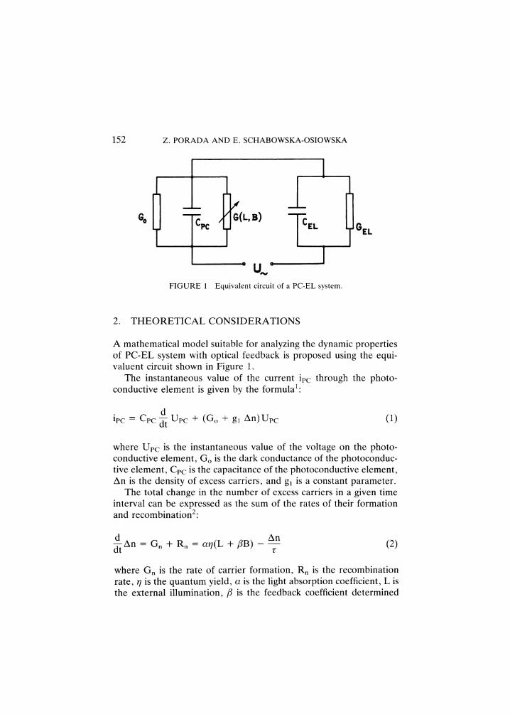
FIGURE Equivalent circuit of a PC-EL system.
GEL
2. THEORETICAL CONSIDERATIONS
A mathematical model suitable for analyzing the dynamic propertiesof PC-EL system with optical feedback is proposed using the equi-valuent circuit shown in Figure 1.
The instantaneous value of the current ipc through the photo-conductive element is given by the formula1:
dilc Cpc Upc -1- (Go + gl An)Upc (1)
where Upc is the instantaneous value of the voltage on the photo-conductive element, Go is the dark conductance of the photoconduc-tive element, Cpc is the capacitance of the photoconductive element,An is the density of excess carriers, and gl is a constant parameter.
The total change in the number of excess carriers in a given timeinterval can be expressed as the sum of the rates of their formationand recombination2:
d An(2)d--An Gn + Rn ctr/(L + fiB)
r
where Gn is the rate of carrier formation, Rn is the recombinationrate, r/is the quantum yield, a is the light absorption coefficient, L isthe external illumination, fl is the feedback coefficient determined
DYNAMIC CHARACTERISTICS OF A THIN FILM PC-EL SYSTEM 153
by geometry and by the degree of spectral overlap of the electro-luminescent cell and the photoconductive element, B is the lumin-ance of the light emitted by an electroluminescent cell, and isthe photoconductivity rise time.
The instantaneous value of the current iEL through the electro-luminescent cell is given by
diEL CEL-UEL -]- GELUEL (3)
where UEL is the instantaneous value of the voltage in the electro-luminescent cell, GEL is the leakage conductance of the electro-luminescent cell, and CEL is the capacitance of the cell.
Since ipc iEt. and Upc Ue UE, where Ue is theinstantaneous value of the exciting voltage of the PC-EL system, theequation
d(CE + C c) + UEL(GEL -k- Go + glAn)
dC,c-Ue + (Go + glAn)Ue (4)
is obtained. The instantaneous value of the luminance B of the lightemitted by an electroluminescent cell (B is the output signal of thelight amplifier) is given by the approximate formula3:
B Bo exp(-?’t) exp (-b IUFL[- 1/2)
where Bo, )’ and b are parameters which are constant for a givenelectroluminescent cell.
The dependence of the luminance B on the time can becalculated by using equations (2), (4) and (5).
For a calculation of the average value of the luminance Ba forsinusoidal excitation voltage Alfrey and Taylor’s formula3 was used:
Ba= Boexp(-f)exp(- b ) (6)
where f is the frequency of the exciting sinusoidal voltage, UEL

154 Z. PORADA AND E. SCHABOWSKA-OSIOWSKA
YPC Uo, and Uo is the amplitude of the exciting voltage,YEL + YecYE is the admittance of an electroluminescent cell:
YEL GEL -t- i2grfCEL,
Yec is the admittance of a photoconductive element4"
YPc Go + go(L + fiB)(1 + 42f2r)-1 + i2a’fCpc
(7)
(8)
and go and r are constant parameters for a given layer.For a real PC-EL system, three additional simplifying assumptions
are usually fulfilled"
Cpc ’ CEL; 2fCEL "> Go; 2JIfCEL GEL.
Then the dependence of the average value of the luminance Ba on theexternal intensity L of illumination can be expressed as follows"
=0
FIGURE 2 B vs. L theoretical characteristics of a PC-EL system.

DYNAMIC CHARACTERISTICS OF A THIN FILM PC-EL SYSTEM 155
Ba Boexp exp
1 + Go + go(L + flBa)(1 + 492f2’21)-I (9)
Equation (9) is true for GEL < goL(1 + 47g2f2z’) -1. The characteris-tics calculated from equ. (9), the dependence of the luminance Ba onthe external illumination L, are shown in Figure 2 for several valuesof ft. It can be seen that for values of fl greater than flLM the thin filmPC-EL systems with optical feedback has a negative slope and a bi-stable nature.
3. EXPERIMENTAL DETAILS AND RESULTS
The photoconductive element (Figure 3) was prepared as a sandwich-type system on a glass substrate. The first layer was .a transparentelectrode of tin-doped In203, obtained by the reactive cathodesputtering of 90%In-10%Sn alloy. The second layer was a photo-conductive CdS films doped with copper and chlorine and evaporatedunder vacuum at a pressure of 6.7 10-3 Pao The thickness of thelayer was 8.3 tm and its recrystallization was carried out for 30 minat 550C in air. The third layer, acting as an electrode, was producedby the vacuum evaporation of indium.
- iI"--"-At
FIGURE 3 The arrangement of the thin film PC-EL system with optical feedback.
156 Z. PORADA AND E. SCHABOWSKA-OSIOWSKA
The second component of PC-EL system, the electroluminescentcell (Figure 3), was a thin film capacitor with an average thickness of1.08 pm produced by the vacuum evaporation of copper-, chlorine-and manganese-doped ZnS. The lower transparent conducting elec-trode was tin-doped In203 on a glass substrate, while the upperelectrode was a vacuum-evaporated thin aluminium film.A sinusoidal voltage of fixed amplitude and frequency was applied
to the PC-EL system. The luminance B of the electroluminescent cellwas measured for various intensities L of illumination of thephotoconductive layer and for values of/3 less than/3LIM. The resultswere compared with values computed using the above theoreticalmodel. The experimental values of the parameters of the photo-conductive element and the electroluminescent cell were found to beas follows" Go 8 10-9 ,--1; ga 2.38 10-7 1x-l-’, z"
3.1 10-5 S" Cec 6.5 10-1 F" b 16.09 V1/2" 951 s-1"
Bo 104 cd.m-2; Czi 2.8 10-9 F; Gzi 7.4 10-8 f2 -’, and/3 0.78 lx.m2cd-.
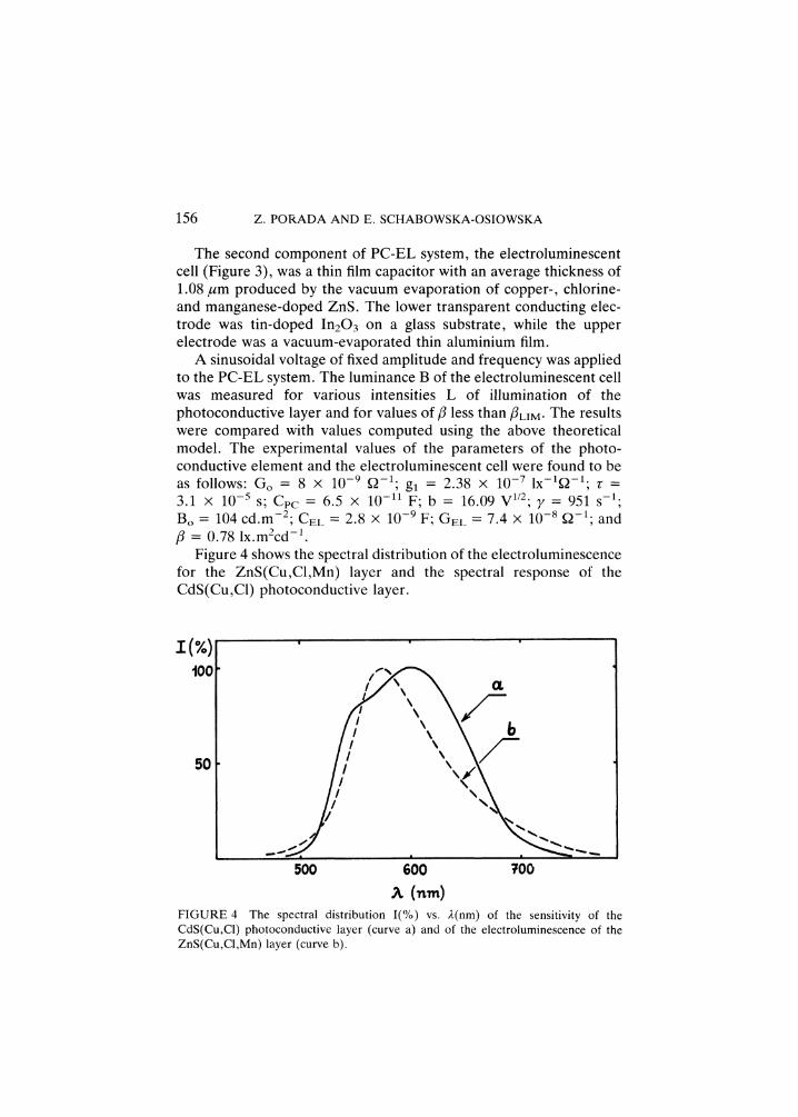
Figure 4 shows the spectral distribution of the electroluminescencefor the ZnS(Cu,C1,Mn) layer and the spectral response of theCdS(Cu,C1) photoconductive layer.
5O
500 600 00
FIGURE 4 The spectral distribution I(%) vs. 2(nm) of the sensitivity of theCdS(Cu,CI) photoconductive layer (curve a) and of the electroluminescence of theZnS(Cu,CI,Mn) layer (curve b).

DYNAMIC CHARACTERISTICS OF A THIN FILM PC-EL SYSTEM 157
Rectangular pulses of the light illuminating the photoconductiveelement were applied to the input of the PC-EL system and theoutput signal was the luminance B(t) of the light emitted from theelectroluminescent cell. The frequency of the light pulses at the inputwas 140 Hz.
Figure 5 shows the time-dependence of luminance for an appliedvoltage of amplitude 280 V at a frequency of 500 Hz, at illuminationof the photoconductive element with light pulses of 0.5 lx for a PC-EL system of feedback coefficient/3 2.0 lx.mZ.cd-1. The illumina-tion intensity was lower than the limiting illumination (LLM 0.76 lx).
Above LLM, the system acted as a bi-stable system, and thedependence of the luminance B on time is shown in Figure 6 at fixedremaining parameters. As can be seen, the investigated PC-EL sys-tem has two stable work points- for the illumination L 0.8 lx,B1 0.4 cd.m-2 and B2 23 cd.m-2.
From a theoretical analysis, the limiting value of the optical feed-back coefficient (/3i) depends on the frequency as shown in Figure7. The limiting value of illumination intensity above which the systemacts as a bi-stable one (if O < L < LLIM, the system is mono-stable,when L > LIIM bi-stable), appears to be a significant parameterfrom the point of view of applications. The dependence of this valueof input signal ELIM on the frequency is given in Figure 8.
TrineFIGURE 5 Luminance vs. time for a frequency of 500 Hz and an amplitude of 280 V( experimental results, values calculated using the theoretical model).

158 Z. PORADA AND E. SCHABOWSKA-OSIOWSKA
0 2 a’ 6 8 t0 t2Time (ms)
FIGURE 6 Dependence of the luminance B on time for illuminations 0.8 Ix and 1.5Ix ( experimental results, values calculated using the theoretical model).
,;)o oo ,,,o ,ooof(Hz)
FIGURE 7 Dependence of the coefficient flt.M on the frequency.

DYNAMIC CHARACTERISTICS OF A THIN FILM PC-EL SYSTEM 159
|
I.tiM ,.
13= 1.8
1
O.5
-2.5,O.2
0.t
I+oo , oo +ooo ,ooo
FIGURE 8 Dependence of the limiting value of illumination intensity on thefrequency.
4. CONCLUSIONS
Both the measurements and the analysis of the proposed theoreticalmodel show that the output signal, i.e. the luminance B(t) of the lightemitted by the electroluminescent cell, exhibited a periodic function.For a PC-EL system excited by a sinusoidal voltage, the frequency fBof the output signal was 2fo, where fo is the frequency of the excitingvoltage.
For low frequencies of the exciting voltage (50 Hz < fo < 200 Hz)the shape of the curves of time dependences of the luminance B(t)varied with the frequency fo, while for high frequencies (fo > 500 Hz)the shape of the curves of luminance versus time showed almost nochange.A thin film PC-EL system can be of bi-stable nature only when its
optical feedback coefficient exceeds the limiting value flX+IM. Thevalue of the coefficient LIM varied with frequency and for the in-vestigated system attained the lowest value (0.8 lx.m2.cd-1) for thefrequency of 300 Hz. The investigated PC-EL system has two stable

160 Z. PORADA AND E. SCHABOWSKA-OSIOWSKA
work points, on condition that input signal L exceeds limiting value ofluminance LtIM.
All the obtained experimental results showed a good agreementwith the characteristics derived from the proposed theoretical model.
REFERENCES
1. Z. Porada, Thin Solid Films, 125,341 (1985).2. P.S. Kireev, Semiconductor Physics, Mir, Moscow 1978 (English translation).3. G.F. Alfrey and J.B. Taylor, Br. J. Appl. Phys., 4, 44S (1955).4. Z. Porada, Thin Solid Films, 109, 213 (1983).5. Z. Porada and E. Schabowska, Thin Solid Films, 66, L55 (1980).

International Journal of
AerospaceEngineeringHindawi Publishing Corporationhttp://www.hindawi.com Volume 2010
RoboticsJournal of
Hindawi Publishing Corporationhttp://www.hindawi.com Volume 2014
Hindawi Publishing Corporationhttp://www.hindawi.com Volume 2014
Active and Passive Electronic Components
Control Scienceand Engineering
Journal of
Hindawi Publishing Corporationhttp://www.hindawi.com Volume 2014
International Journal of
RotatingMachinery
Hindawi Publishing Corporationhttp://www.hindawi.com Volume 2014
Hindawi Publishing Corporation http://www.hindawi.com
Journal ofEngineeringVolume 2014
Submit your manuscripts athttp://www.hindawi.com
VLSI Design
Hindawi Publishing Corporationhttp://www.hindawi.com Volume 2014
Hindawi Publishing Corporationhttp://www.hindawi.com Volume 2014
Shock and Vibration
Hindawi Publishing Corporationhttp://www.hindawi.com Volume 2014
Civil EngineeringAdvances in
Acoustics and VibrationAdvances in
Hindawi Publishing Corporationhttp://www.hindawi.com Volume 2014
Hindawi Publishing Corporationhttp://www.hindawi.com Volume 2014
Electrical and Computer Engineering
Journal of
Advances inOptoElectronics
Hindawi Publishing Corporation http://www.hindawi.com
Volume 2014
The Scientific World JournalHindawi Publishing Corporation http://www.hindawi.com Volume 2014
SensorsJournal of
Hindawi Publishing Corporationhttp://www.hindawi.com Volume 2014
Modelling & Simulation in EngineeringHindawi Publishing Corporation http://www.hindawi.com Volume 2014
Hindawi Publishing Corporationhttp://www.hindawi.com Volume 2014
Chemical EngineeringInternational Journal of Antennas and
Propagation
International Journal of
Hindawi Publishing Corporationhttp://www.hindawi.com Volume 2014
Hindawi Publishing Corporationhttp://www.hindawi.com Volume 2014
Navigation and Observation
International Journal of
Hindawi Publishing Corporationhttp://www.hindawi.com Volume 2014
DistributedSensor Networks
International Journal of