dynamic blocks explained -...
TRANSCRIPT
Dynamic Blocks Explained John Beltran – Autodesk, Inc.
GD501-1 Gain an understanding of AutoCAD software’s Dynamic Block feature and how to create more powerful and flexible Block libraries. Learn the basic concepts behind Dynamic Block technology and hear detailed explanations of each Dynamic Block parameter and action. Understand some of the common pitfalls and limitations of Dynamic Blocks and how to avoid them. A short presentation introduces each concept, followed by a demonstration. This lecture will benefit all CAD professionals who use Blocks in AutoCAD and want to take advantage of Dynamic Block features. Attendees should have a general comprehension of AutoCAD. Key Topics: - Use the AutoCAD Block editor to create blocks - Combine block parameters and actions to create Dynamic Blocks - Use look-up tables to create relationships between Dynamic Block properties - Avoid common Dynamic Block pitfalls - Understand how custom applications interact with Dynamic Blocks
About the Speaker: As a member of the AutoCAD Development Team at Autodesk, John has contributed to every AutoCAD release for the past 14 years. He is proud to have been one of the lead engineers for the Dynamic Blocks feature in AutoCAD 2006, and has worked on many other AutoCAD features, including 3D Solid Editing, Annotation Scaling, and the Properties palette. Prior to Autodesk, John worked for an Autodesk developer where he was introduced to AutoCAD Release 11. He has been an avid user ever since. John holds a Master of Science degree in Structural Mechanics from the University of California at Los Angeles. [email protected]


Dynamic Blocks Explained
Getting Started With Dynamic Blocks
What is a Dynamic Block? A dynamic block is a block definition that contains custom properties and grips in addition to the geometry contained in legacy block definitions. A dynamic block has flexibility and intelligence. A dynamic block reference can easily be changed in a drawing while you work. You can manipulate the geometry in a dynamic block reference through custom grips or custom properties.
A dynamic block reference may be displayed differently in the drawing than the original block definition. However, the displayed block reference remains a reference to the original block definition.
In addition to the geometry contained in all block definitions, dynamic block definitions contain parameters and actions. Parameters define custom grips and properties. Actions define how the geometry of a dynamic block reference will move or change when the block reference is manipulated in a drawing.
Examples of dynamic blocks include doors whose opening can be stretched by changing a custom “Width” property or moving a grip, callout symbols with different symbols depending on the settings of a custom property picked from a list, blocks with automatically computed part numbers, and many others.
Creating Blocks in the Block Editor (BEDIT Command) AutoCAD 2006 introduced the Block Editor (BEDIT command). The Block Editor looks and acts like model space, but all of the geometry you create becomes part of the block definition.
The Block Editor allows block authors to:
• Create new blocks or edit existing blocks • Change the block description, block units, and scale and explode settings • Edit geometry using existing AutoCAD commands • Add parameters, which create custom grips and properties for changing the geometry of
individual blocks after they have been inserted into a drawing • Add actions, which define how the block will move or change when the block reference is
manipulated in a drawing
Edit Block Definition Dialog Box The BEDIT command initially displays the Edit Block Definition dialog box. This dialog box displays a list of existing blocks to edit or allows you to enter a new block name. The dialog shows a preview of the selected block and the description of the block. Dynamic block previews have a small lightning bolt in the bottom right corner.
The <Current Drawing> block is actually the Model Space tab of the current drawing. To create custom grips and properties for drawings that are part of a block library edit them using the <Current Drawing> entry in the list.
Tip: Double-clicking on a block in model or paper space launches the BEDIT command and selects the corresponding block from the Edit Block Definition dialog box. You can disable this by setting the BLOCKEDITLOCK system variable to 1.
2
Dynamic Blocks Explained
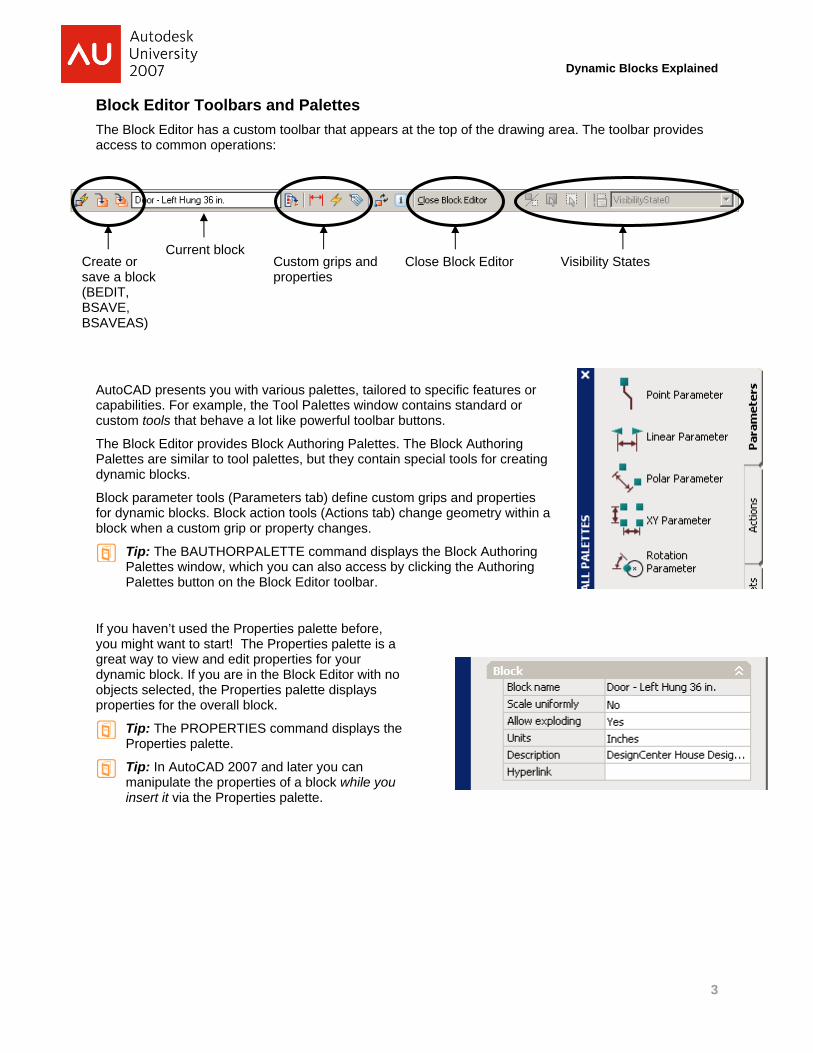
Block Editor Toolbars and Palettes The Block Editor has a custom toolbar that appears at the top of the drawing area. The toolbar provides access to common operations:
Create or save a block (BEDIT, BSAVE, BSAVEAS)
Current blockC
AutoCAD presents you with various palettes, tailored to specific features or capabilities. For example, the Tool Palettes window contains standard or custom tools that behave a lot like powerful toolbar buttons.
The Block Editor provides Block Authoring Palettes. The Block Authoring Palettes are similar to tool palettes, but they contain special tools for creating dynamic blocks.
Block parameter tools (Parameters tab) define custom grips and properties for dynamic blocks. Block action tools (Actions tab) change geometry within ablock when a custom grip or property changes.
Tip: The BAUTHORPALETTE command displays the Block Authoring Palettes window, which you can also access by clicking the Authoring Palettes button on the Block Editor toolbar.
If you haven’t used the Properties palette before, you might want to start! The Properties palette is a great way to view and edit properties for your dynamic block. If you are in the Block Editor with no objects selected, the Properties palette displays properties for the overall block.
Tip: The PROPERTIES command displays the Properties palette.
Tip: In AutoCAD 2007 and later you can manipulate the properties of a block while you insert it via the Properties palette.
ustom griproperties
s and p
Close Block Editor Visibility States
3

Dynamic Blocks Explained
Making Blocks Dynamic
Parameters and Actions Dynamic block definitions contain objects and attributes just like other block definitions and you place them in drawings using the same INSERT command. They can be nested and counted using AutoCAD’s data extraction feature.
What distinguishes a dynamic block from one that is not dynamic is the presence of parameters and actions. Parameters define custom properties and grips, and actions define how the block reference will move or change when the block reference is manipulated in a drawing. Parameters and actions allow different references to the block to be manipulated separately from the definition. Depending on how the block was authored, manipulated references may have different (sometimes significantly different) visual representations from each other and from the initial block definition.
Dynamic block parameters define the custom properties and grips that are displayed when you select a dynamic block reference in a drawing. When these custom properties or grips are changed, the underlying actions are triggered, changing the appearance of the block reference.
Dynamic block actions define how the geometry of a block reference will change when a property of the block reference changes. For example, changing a distance property of a dynamic block reference might move geometry in the block to make a door wider. You might think of dynamic block actions as stand-ins for regular AutoCAD commands like MOVE, ROTATE, SCALE, MIRROR, and STRETCH.
Parameters and actions work together but can only be used in certain combinations. Appendix A lists all of the parameters and actions, and how they can be combined.
Defining Custom Grips and Properties: Adding Parameters You add parameters to a dynamic block definition in the Block Editor. In the Block Editor, parameters have an appearance similar to dimensions. Parameters define custom properties for the block. Parameters also specify positions, distances, and angles for geometry in the block reference. When you add a parameter to a dynamic block definition, the parameter defines one or more custom properties for the block, and one or more custom grips for the block.
Key Concept: Think of Block parameters as exposing the pand grips on a block that your users interact with. They define whatproperties or grips can vary from one block reference to another.
ic block d
roperties
A dynam efinition must contain at least one parameter. When you
he Parameters tab of the
add a parameter to a dynamic block definition, grips associated with key points of the parameter are automatically added.
Use the BPARAMETER command or the tools on tBlock Authoring Palettes window to add parameters to blocks.
4
Dynamic Blocks Explained
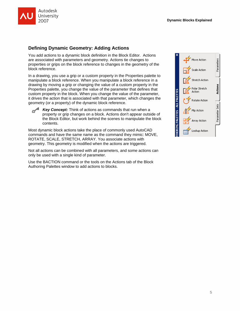
Defining Dynamic Geometry: Adding Actions You add actions to a dynamic block definition in the Block Editor. Actions are associated with parameters and geometry. Actions tie changes to properties or grips on the block reference to changes in the geometry of the block reference.
In a drawing, you use a grip or a custom property in the Properties palette to manipulate a block reference. When you manipulate a block reference in a drawing by moving a grip or changing the value of a custom property in the Properties palette, you change the value of the parameter that defines that custom property in the block. When you change the value of the parameter, it drives the action that is associated with that parameter, which changes the geometry (or a property) of the dynamic block reference.
Key Concept: Think of actions as commands that run when a property or grip changes on a block. Actions don’t appear outside of the Block Editor, but work behind the scenes to manipulate the block contents.
Most dynamic block actions take the place of commonly used AutoCAD commands and have the same name as the command they mimic: MOVE, ROTATE, SCALE, STRETCH, ARRAY. You associate actions with geometry. This geometry is modified when the actions are triggered.
Not all actions can be combined with all parameters, and some actions can only be used with a single kind of parameter.
Use the BACTION command or the tools on the Actions tab of the Block Authoring Palettes window to add actions to blocks.
5
Dynamic Blocks Explained
Using Simple Parameters and Actions
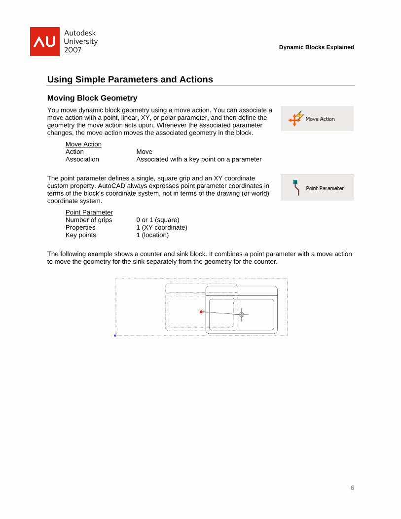
Moving Block Geometry You move dynamic block geometry using a move action. You can associate a move action with a point, linear, XY, or polar parameter, and then define the geometry the move action acts upon. Whenever the associated parameter changes, the move action moves the associated geometry in the block.
Move Action Action Move Association Associated with a key point on a parameter
The point parameter defines a single, square grip and an XY coordinate custom property. AutoCAD always expresses point parameter coordinates in terms of the block’s coordinate system, not in terms of the drawing (or world) coordinate system.
Point Parameter Number of grips 0 or 1 (square) Properties 1 (XY coordinate) Key points 1 (location)
The following example shows a counter and sink block. It combines a point parameter with a move action to move the geometry for the sink separately from the geometry for the counter.
6
Dynamic Blocks Explained
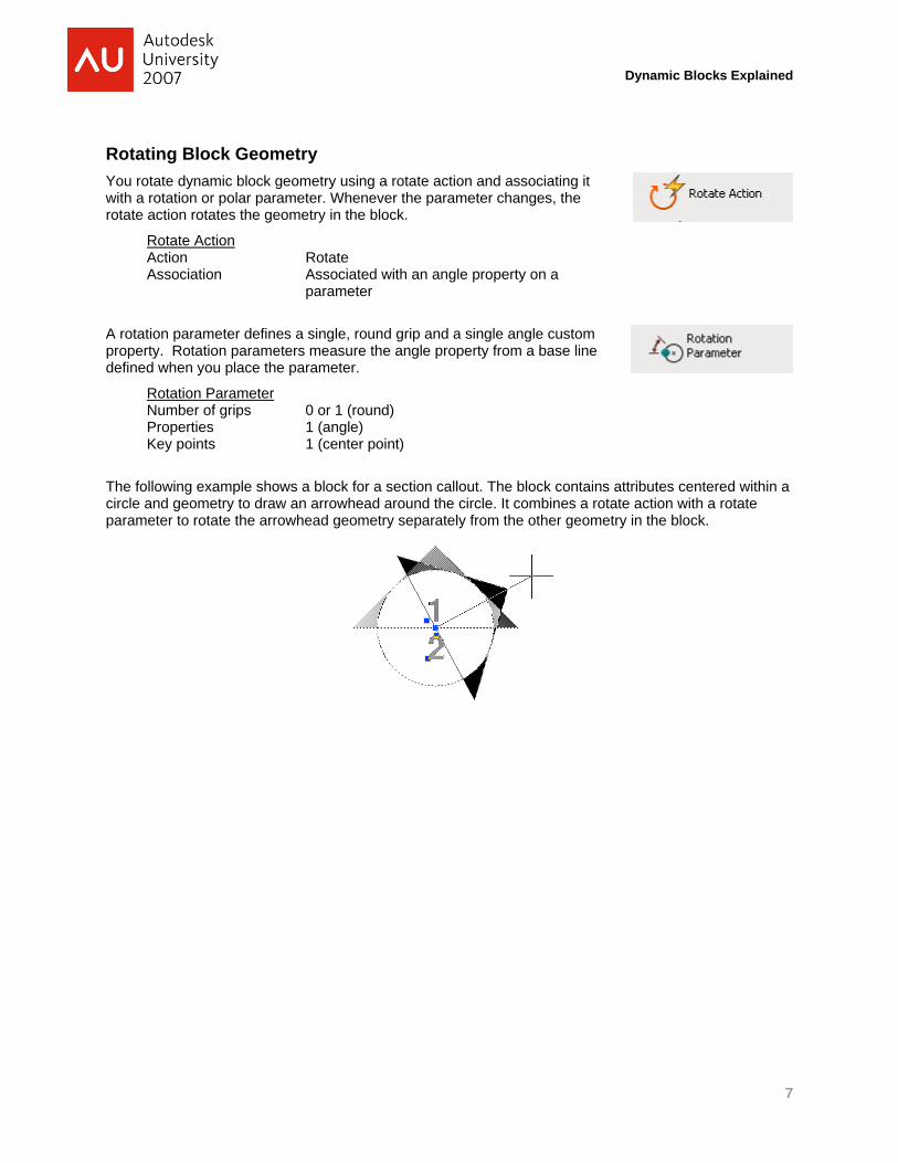
Rotating Block Geometry You rotate dynamic block geometry using a rotate action and associating it with a rotation or polar parameter. Whenever the parameter changes, the rotate action rotates the geometry in the block.
Rotate Action Action Rotate Association Associated with an angle property on a
parameter
A rotation parameter defines a single, round grip and a single angle custom property. Rotation parameters measure the angle property from a base line defined when you place the parameter.
Rotation Parameter Number of grips 0 or 1 (round) Properties 1 (angle) Key points 1 (center point)
The following example shows a block for a section callout. The block contains attributes centered within a circle and geometry to draw an arrowhead around the circle. It combines a rotate action with a rotate parameter to rotate the arrowhead geometry separately from the other geometry in the block.
7
Dynamic Blocks Explained
Tools and Techniques for Authoring Dynamic Blocks Dynamic Blocks offer a rich set of features for creating very useful and complex block libraries. This can create challenges to both block authors and block users when blocks become overly complex.
Will your blocks need to updated or maintained after you create them? How can someone in your organization understand how the parameters and actions in the block work together if they need to make change or enhancements to them later?
Will a user in your organization understand how to interact with one of your dynamic blocks? Which grips manipulate which block properties? Will your users understand what the properties mean, for example how will they identify the door opening property on a door block and the grips that manipulate the opening?
AutoCAD’s Helps to Identify Relationships Visually When you create new dynamic blocks or modify existing dynamic blocks, AutoCAD provides several tools to help you understand how the parameters and actions in the dynamic block work together.
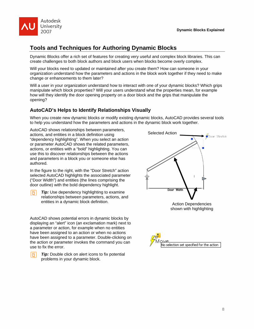
AutoCAD shows relationships between parameters, actions, and entities in a block definition using “dependency highlighting”. When you select an action or parameter AutoCAD shows the related parameters, actions, or entities with a “bold” highlighting. You can use this to discover relationships between the actions and parameters in a block you or someone else has authored.
In the figure to the right, with the “Door Stretch” action selected AutoCAD highlights the associated parameter (“Door Width”) and entities (the lines comprising the door outline) with the bold dependency highlight.
Tip: Use dependency highlighting to examine relationships between parameters, actions, and entities in a dynamic block definition.
AutoCAD shows potential errors in dynamic blocks by displaying an “alert” icon (an exclamation mark) next to a parameter or action, for example when no entities have been assigned to an action or when no actions have been assigned to a parameter. Double-clicking on the action or parameter invokes the command you can use to fix the error.
Tip: Double click on alert icons to fix potential problems in your dynamic block.
Action Dependencies shown with highlighting
Selected Action
8
Dynamic Blocks Explained
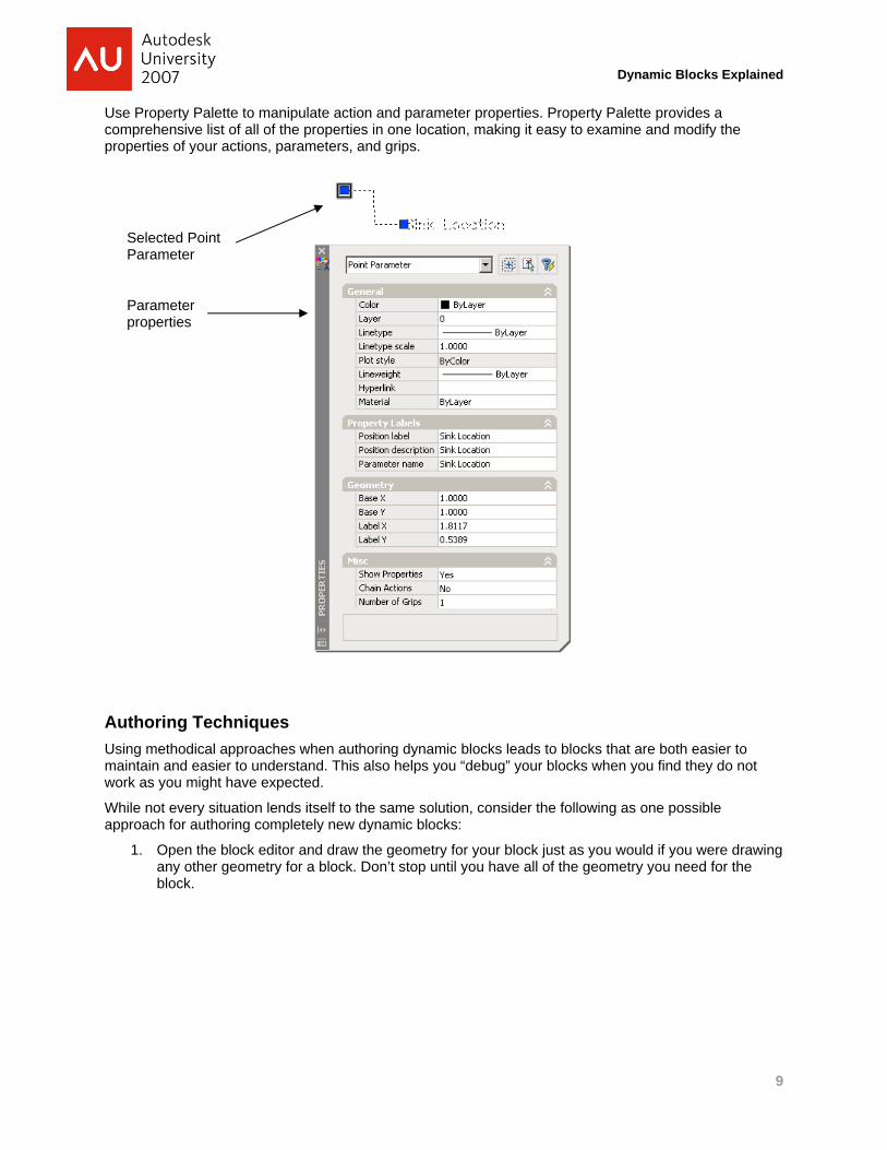
Use Property Palette to manipulate action and parameter properties. Property Palette provides a comprehensive list of all of the properties in one location, making it easy to examine and modify the properties of your actions, parameters, and grips.
Selected Point Parameter
Parameter properties
Authoring Techniques Using methodical approaches when authoring dynamic blocks leads to blocks that are both easier to maintain and easier to understand. This also helps you “debug” your blocks when you find they do not work as you might have expected.
While not every situation lends itself to the same solution, consider the following as one possible approach for authoring completely new dynamic blocks:
1. Open the block editor and draw the geometry for your block just as you would if you were drawing any other geometry for a block. Don’t stop until you have all of the geometry you need for the block.
9
Dynamic Blocks Explained
2. Add parameters and actions in pairs to manipulate the block content. Thinking about all of the manipulations you want to add, start with the simpler combinations and finish with the more complex combinations. Add actions like lookup tables last after you have added all of the other parameters and actions.
Tip: When deciding what kind of parameter and action to add, ask yourself “What do I want the user to do?” You’ll find the name of the action and parameter in your answer. For example “I want the user to MOVE the door jamb of the block using a grip that moves along a LINE”. In this case you probably want a LINEAR parameter combined with a MOVE action.
Tip: There are many ways to accomplish the same effect with dynamic blocks. Try to choose the simplest solution and avoid authoring blocks that are difficult to understand, use, and maintain.
3. Give meaningful names and descriptions to the parameters and actions as you add them to your block. For example, “Move Pump” is more descriptive and useful than the default label “Move” assigned by AutoCAD to move actions.
Tip: AutoCAD assigns generic names and labels to new parameters and actions. Assigning names to parameters and actions which reflect their purpose makes the block easier to maintain and helps users of your block understand how to manipulate it.
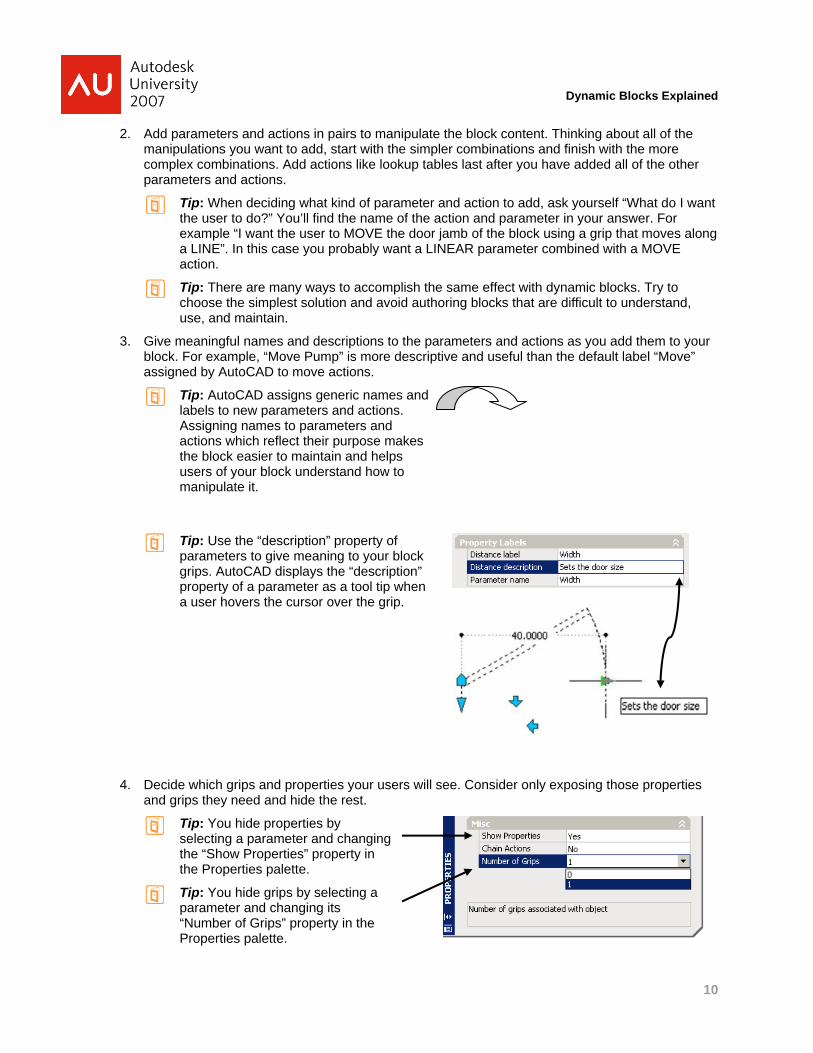
Tip: Use the “description” property of parameters to give meaning to your block grips. AutoCAD displays the “description” property of a parameter as a tool tip when a user hovers the cursor over the grip.
4. Decide which grips and properties your users will see. Consider only exposing those properties and grips they need and hide the rest.
Tip: You hide properties by selecting a parameter and changing the “Show Properties” property in the Properties palette.
Tip: You hide grips by selecting a parameter and changing its “Number of Grips” property in the Properties palette.
10
Dynamic Blocks Explained
5. Test your parameters and actions as you add them. Insert the block into model space, select the block and move its grips. Does the block change as you expect? Examine the properties listed in the Properties palette and change the property values. Do different values affect the appearance of the block as you expect? If anything doesn’t behave the way you expect go back into the block editor and correct the problem. Don’t add anything else to the block until the block behaves as you expect.
Tip: Use the Properties dialog to modify the behavior of your parameters and actions after you place them. In some cases there may be commands (e.g. BACTIONSET, BLOOKUPTABLE, and BVSTATES) that you should use to modify the block behavior.
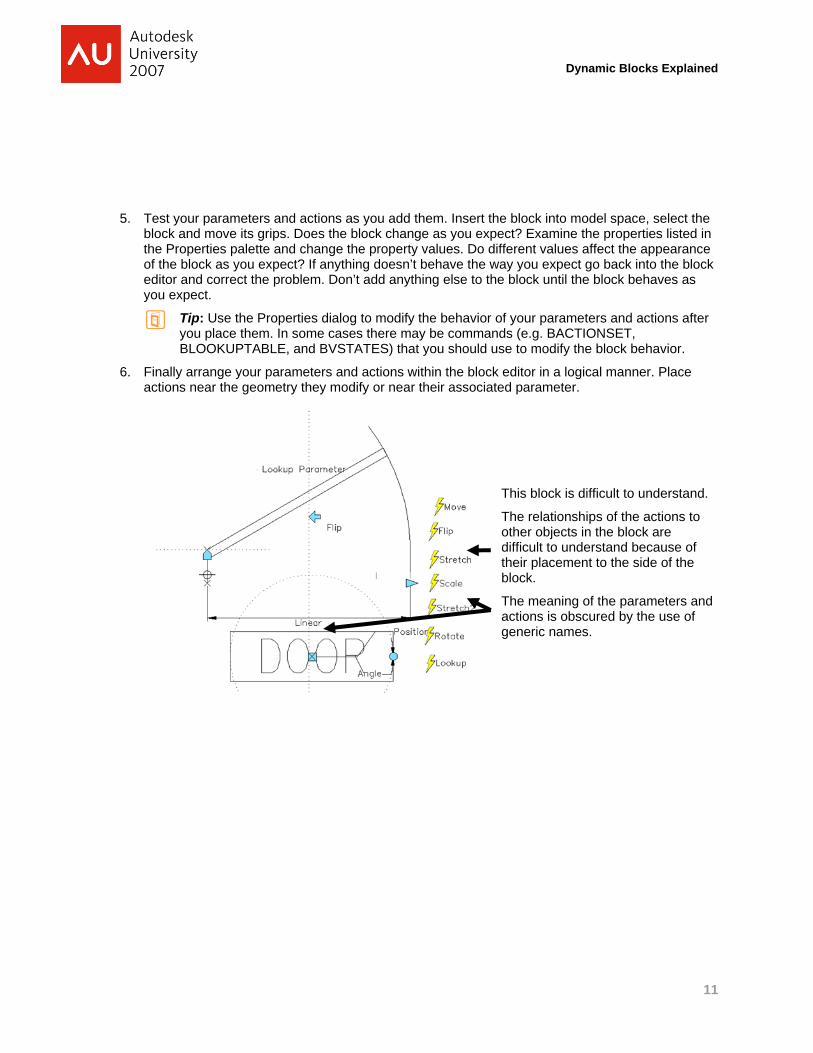
6. Finally arrange your parameters and actions within the block editor in a logical manner. Place actions near the geometry they modify or near their associated parameter.
This block is difficult to understand.
The relationships of the actions to other objects in the block are difficult to understand because of their placement to the side of the block.
The meaning of the parameters and actions is obscured by the use of generic names.
11

Dynamic Blocks Explained
This block is easier to understand.
Note the use of meaningful parameter and action names, and the placement of actions near the geometry.
12
Dynamic Blocks Explained
Using Intermediate Parameters and Actions
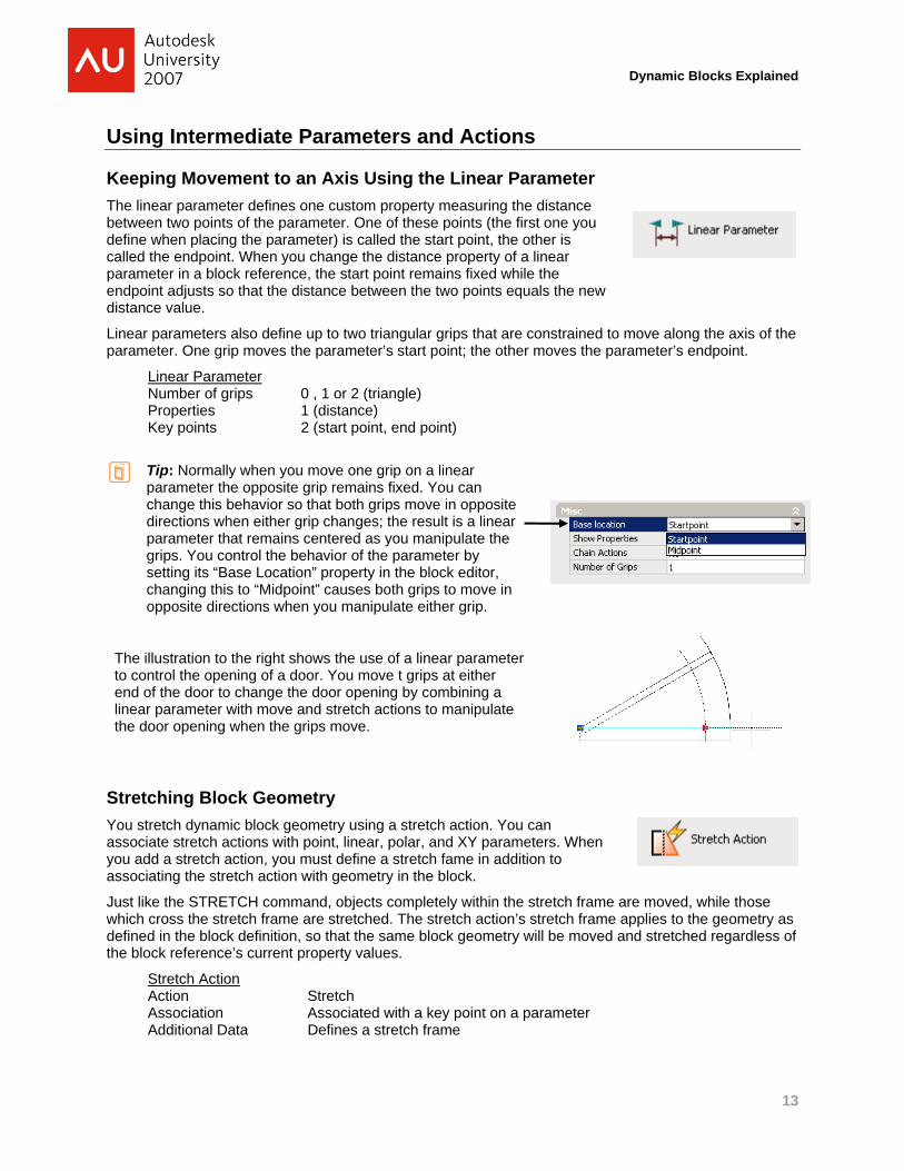
Keeping Movement to an Axis Using the Linear Parameter The linear parameter defines one custom property measuring the distance between two points of the parameter. One of these points (the first one you define when placing the parameter) is called the start point, the other is called the endpoint. When you change the distance property of a linear parameter in a block reference, the start point remains fixed while the endpoint adjusts so that the distance between the two points equals the new distance value.
Linear parameters also define up to two triangular grips that are constrained to move along the axis of the parameter. One grip moves the parameter’s start point; the other moves the parameter’s endpoint.
Linear Parameter
arameter
g a
Number of grips 0 , 1 or 2 (triangle) Properties 1 (distance) Key points 2 (start point, end point)
Tip: Normally when you move one grip on a linear parameter the opposite grip remains fixed. You can change this behavior so that both grips move in opposite directions when either grip changes; the result is a linear parameter that remains centered as you manipulate the grips. You control the behavior of the parameter by setting its “Base Location” property in the block editor, changing this to “Midpoint” causes both grips to move in opposite directions when you manipulate either grip.
The illustration to the right shows the use of a linear pto control the opening of a door. You move t grips at either end of the door to change the door opening by combininlinear parameter with move and stretch actions to manipulate the door opening when the grips move.
Stretching Block Geometry You stretch dynamic block geometry using a stretch action. You can associate stretch actions with point, linear, polar, and XY parameters. When you add a stretch action, you must define a stretch fame in addition to associating the stretch action with geometry in the block.
Just like the STRETCH command, objects completely within the stretch frame are moved, while those which cross the stretch frame are stretched. The stretch action’s stretch frame applies to the geometry as defined in the block definition, so that the same block geometry will be moved and stretched regardless of the block reference’s current property values.
Stretch Action Action Stretch Association Associated with a key point on a parameter Additional Data Defines a stretch frame
13
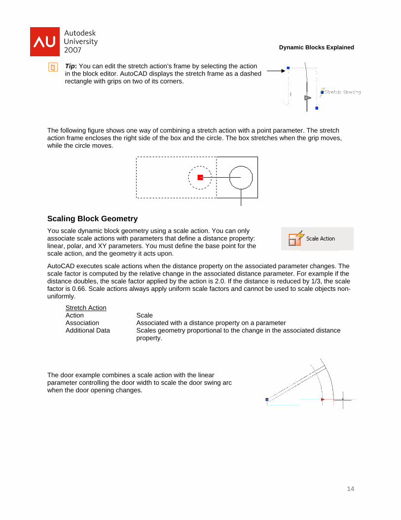
Tipin threct
Dynamic Blocks Expll
The followaction framwhile the
ScalingYou scaleassociate linear, polscale actio
AutoCAD scale factdistance dfactor is 0uniformly.
StreActAssAdd
The door parametewhen the
: You can edihe block editotangle with gr
wing figure shme encloses circle moves.
Block Geoe dynamic blo scale actionslar, and XY paon, and the g
executes scaor is computedoubles, the s0.66. Scale ac.
etch Action
tion sociation ditional Data
example comr controlling tdoor opening
it the stretch aor. AutoCAD drips on two of
ows one waythe right side.
ometry ock geometry s with paramearameters. Yoeometry it ac
ale actions whed by the relascale factor actions always
ScaleAssoScaleprope
mbines a scalehe door width
g changes.
action’s framedisplays the sf its corners.
y of combininge of the box an
using a scaleeters that defiou must defin
cts upon.
hen the distanative change ipplied by the apply uniform
e ociated with a es geometry perty.
e action with th to scale the
e by selectingstretch frame
g a stretch acnd the circle.
e action. You ine a distancene the base p
nce property on the associaaction is 2.0.
m scale factor
distance proproportional t
the linear door swing a
g the action as a dashed
ction with a poThe box stret
can only e property: oint for the
on the associated distance . If the distancrs and cannot
perty on a pato the change
arc
oint parametetches when th
iated parameparameter. Fce is reducedt be used to s
arameter e in the assoc
er. The stretchhe grip moves
ter changes. For example ifd by 1/3, the sscale objects
iated distance
ained
14
h s,
The f the scale non-
e

Dynamic Blocks Explained
Specifying Value Sets AutoCAD allows you to restrict the values that can be assigned to most custom properties on dynamic blocks. In AutoCAD, these are called value sets, and you define them for the parameter exposing the custom properties. There are three kinds of value sets you can define:
1. “None” value sets allow you to define a range of allowed values by specifying a minimum and maximum value for the property. Minimum values must be between zero and the default value of the property. Maximum values can be either blank (indicating no maximum) or must be equal to or larger than the default property value.
2. “Increment” value sets allow you to define a set of equally spaced allowed values, with optionally defined minimum and/or maximum values that behave identically to the minimum and maximum values of the “None” value set.
3. “List” value sets restrict the allowed values for a property to a fixed list of values. You define the list of allowed values by selecting the parameter in the Block Editor and clicking on the button next to the Value List property in the Properties palette. AutoCAD automatically adds the default value of the property to the list and does not allow it to be removed.
Properties with list value sets show a drop-down list box of the values when editing the value on a block reference.
In a drawing, when you manipulate grips on parameters that have a specified value set, AutoCAD constrains the grip movement between any minimum and maximum value and snaps the grip to the closest increment or list value if any are defined.
AutoCAD displays marks in both the Block Editor and in the drawing window to indicate that a value set is specified. AutoCAD displays minimum and maximum values in the Block Editor by tick marks at the minimum and maximum values connected by a line. In a drawing, there is no visual indication of minimum and maximum values.
AutoCAD displays increment or list values are as tick marks in both the Block Editor, and in a drawing when manipulating a grip on the associated parameter.
The block at the right shows the use of value sets to control the opening of a door block. A linear parameter controls the door penning which must conform to standard door sizes of 24, 30, and 36 inches. The tick marks indicate the allowed door sizes.
15
Dynamic Blocks Explained
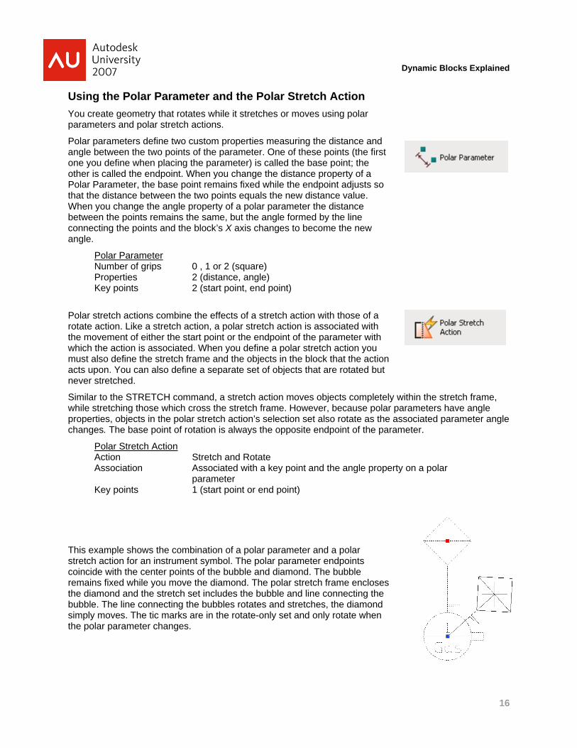
Using the Polar Parameter and the Polar Stretch Action You create geometry that rotates while it stretches or moves using polar parameters and polar stretch actions.
Polar parameters define two custom properties measuring the distance and angle between the two points of the parameter. One of these points (the first one you define when placing the parameter) is called the base point; the other is called the endpoint. When you change the distance property of a Polar Parameter, the base point remains fixed while the endpoint adjusts so that the distance between the two points equals the new distance value. When you change the angle property of a polar parameter the distance between the points remains the same, but the angle formed by the line connecting the points and the block’s X axis changes to become the new angle.
Polar Parameter Number of grips 0 , 1 or 2 (square) Properties 2 (distance, angle) Key points 2 (start point, end point)
Polar stretch actions combine the effects of a stretch action with those of a rotate action. Like a stretch action, a polar stretch action is associated with the movement of either the start point or the endpoint of the parameter with which the action is associated. When you define a polar stretch action you must also define the stretch frame and the objects in the block that the action acts upon. You can also define a separate set of objects that are rotated but never stretched.
Similar to the STRETCH command, a stretch action moves objects completely within the stretch frame, while stretching those which cross the stretch frame. However, because polar parameters have angle properties, objects in the polar stretch action’s selection set also rotate as the associated parameter angle changes. The base point of rotation is always the opposite endpoint of the parameter.
Polar Stretch Action Action Stretch and Rotate Association Associated with a key point and the angle property on a polar
parameter Key points 1 (start point or end point)
This example shows the combination of a polar parameter and a polar stretch action for an instrument symbol. The polar parameter endpoints coincide with the center points of the bubble and diamond. The bubble remains fixed while you move the diamond. The polar stretch frame encloses the diamond and the stretch set includes the bubble and line connecting the bubble. The line connecting the bubbles rotates and stretches, the diamond simply moves. The tic marks are in the rotate-only set and only rotate when the polar parameter changes.
16
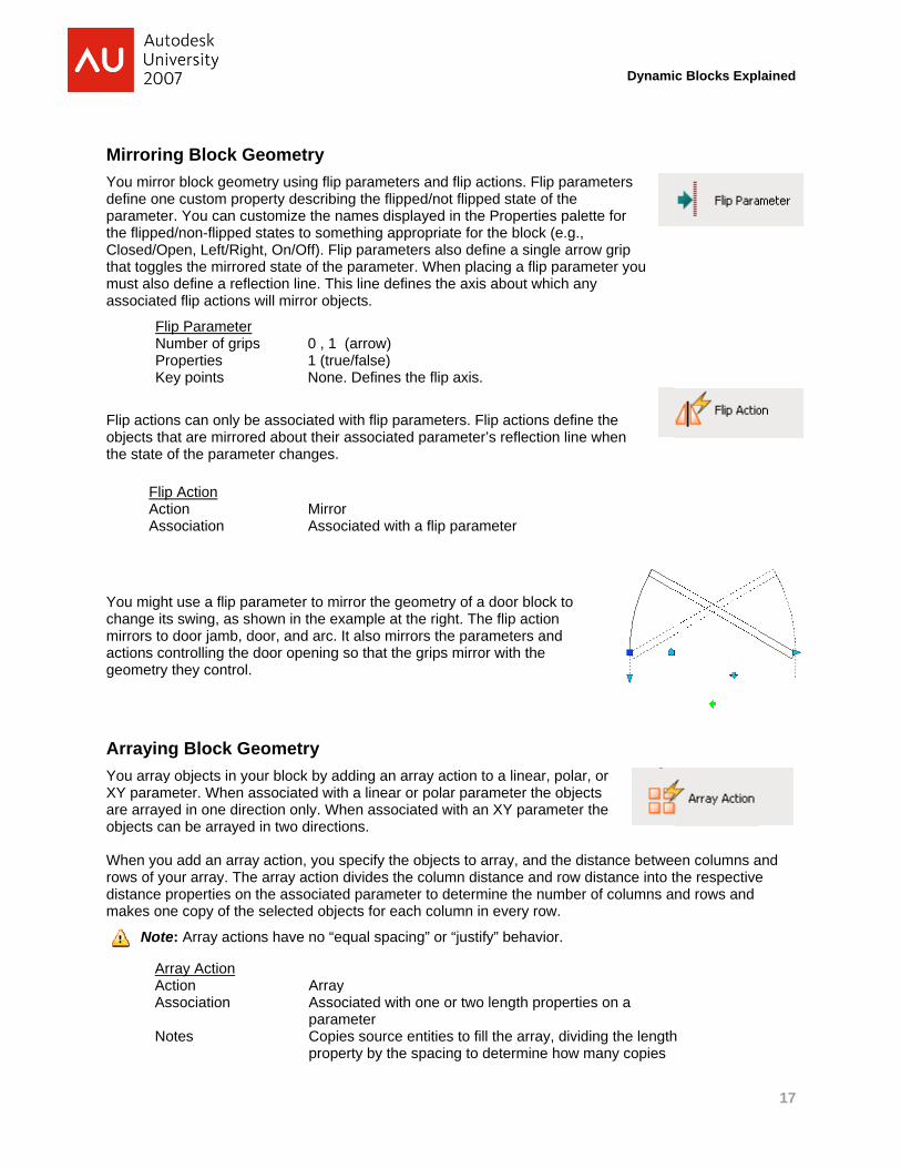
MirrorinYou mirrodefine oneparametethe flippedClosed/Othat togglemust alsoassociate
FlNuPrKe
Flip actionobjects ththe state o
FlipActAss
You mighchange itsmirrors to actions cogeometry
ArrayinYou arrayXY paramare arrayeobjects ca
When yourows of yodistance pmakes on
Note
Dynamic Blocks Expll
ArAcAs
No
ng Block Gor block geome custom pror. You can cud/non-flipped pen, Left/Righes the mirrore
o define a refled flip actions
ip Parameter
umber of griproperties ey points
ns can only beat are mirroreof the parame
p Action
tion sociation
t use a flip pas swing, as shdoor jamb, d
ontrolling the they control.
g Block Gey objects in yometer. When aed in one direan be arrayed
u add an arrayour array. Theproperties on ne copy of the
e: Array actio
rray Action
ction ssociation
otes
Geometry metry using flip
perty describustomize the n
states to somht, On/Off). Fed state of theection line. Thwill mirror ob
s 0 , 1
1 (truNone
e associated ed about theireter changes.
MirroAsso
arameter to mhown in the e
door, and arc.door opening
eometry our block by aassociated witection only. Wd in two direct
y action, you e array actionthe associate
e selected obj
ns have no “e
ArrayAssoparaCopiprop
p parameters ing the flippednames displamething approlip parametere parameter. his line definebjects.
(arrow) ue/false) e. Defines the
with flip parar associated p.
or ociated with a
mirror the geomexample at the It also mirror
g so that the g
adding an arrath a linear or
When associattions.
specify the on divides the ced parameterects for each
equal spacing
y ociated with oameter ies source en
perty by the sp
and flip actiod/not flipped syed in the Pro
opriate for thers also defineWhen placing
es the axis ab
e flip axis.
meters. Flip aparameter’s r
a flip paramete
metry of a dooe right. The flirs the paramegrips mirror w
ay action to apolar parame
ted with an XY
bjects to arracolumn distanr to determine column in ev
g” or “justify” b
one or two len
ntities to fill thepacing to dete
ons. Flip paramstate of the operties palet
e block (e.g., a single arrog a flip param
bout which any
actions defineeflection line
er
or block to ip action eters and ith the
linear, polar,eter the objecY parameter t
ay, and the disnce and row de the number very row.
behavior.
ngth propertie
e array, dividiermine how m
meters
tte for
ow grip meter you
y
e the when
or cts the
stance betwedistance into tof columns a
s on a
ing the lengthmany copies
en columns athe respectivend rows and
ained
17
and e
h

The followinterior wastretches inches of
KeepingUsing an relationshmeasuringparameteparameteendpoint. corner is c
When youwhile the the new dtheir relat
XY paramhas zero, endpoint. present th
NoteparaX disaxis.
XY NumProKey
This examone columcorners ofthe block move any
Dynamic Blocks Expll
wing examplealls. It combinthe drywall awall length.
g Things SXY paramete
hip in your blog the horizontr. One of thesr) is called the(The bottom called the YC
u change eithendpoint adju
distance valueive relationsh
meters also deone, two, or fWhen two gr
hey are placed
e: XY paramemeters to inc
stance always
Parameter
mber of grips operties y points
mple uses an mn moves twof the rectangland associate
y one grip thre
shows a blocnes a linear pas the grip mo
Square wither you can defock. An XY patal and verticase corners (the base point, right corner is
Corner).
er of the distausts so that ee (depending hip at all times
efine up to foufour grips at arips are presed at each cor
eters must alwcline their X ans lies parallel
, 1, 0 2
2 distaFour,
XY parameteo other colume. The block es a move acee columns m
to cr
ck used to disarameter with
oves, while the
h the XY Pafine grips that
arameter definal distance behe first one yothe opposite s called the X
ance propertieither the horizon which one
s, so changing
ur rectangularany time. Wheent they are prner.
ways be alignend Y distancethe block X a
2,or 4 (squareance (horizonone at each c
er to keep foumns move to k
places an XYction with eacmove with it.
reate.
splay the crosh a stretch ace array action
arameter t maintain a rnes two custoetween two coou define whe
corner is callXcorner, and t
es of an XY pzontal or vertie changed). Ag one distanc
r grips that caen an XY parlaced at the b
ed with the ble properties reaxis, the Y dis
e) ntal, vertical)corner.
r columns aligkeep the four cY parameter ah XY parame
ss-section of wction and an an causes a ne
ectangular om properties orners of the en placing theled the the top left
parameter, theical distance b
All four cornerce moves both
an move in anrameter has obase and end
lock X and Y elative to the stance always
gned; whenevcolumns at th
at the corners eter grip. Whe
wood frame carray action. Tew stud to app
e
e base point rbetween the trs of the paramh of the affect
ny direction. Aonly one grip ipoints. When
axes. You cablock’s coord
s lies parallel
ver he
of en you
construction The stretch acpear every 16
remains fixedtwo points eqmeter maintated corners.
An XY parameit is placed at n four grips ar
annot rotate Xdinate systemto the block Y
ained
18
ction 6
d quin
als
eter the
re
XY m. The Y
Dynamic Blocks Explained
Managing Block Rotation and Insertion Points
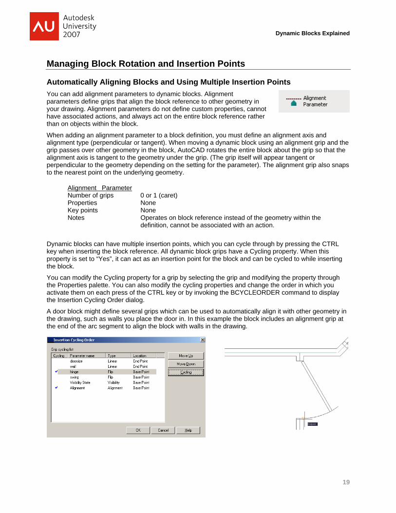
Automatically Aligning Blocks and Using Multiple Insertion Points You can add alignment parameters to dynamic blocks. Alignment parameters define grips that align the block reference to other geometry in your drawing. Alignment parameters do not define custom properties, cannot have associated actions, and always act on the entire block reference rather than on objects within the block.
When adding an alignment parameter to a block definition, you must define an alignment axis and alignment type (perpendicular or tangent). When moving a dynamic block using an alignment grip and the grip passes over other geometry in the block, AutoCAD rotates the entire block about the grip so that the alignment axis is tangent to the geometry under the grip. (The grip itself will appear tangent or perpendicular to the geometry depending on the setting for the parameter). The alignment grip also snaps to the nearest point on the underlying geometry.
Alignment Parameter
Dynamic blocks can have multiple insertion points, which you can cycle through by pressing the CTRL key when inserting the block reference. All dynamic block grips have a Cycling property. When this property is set to “Yes”, it can act as an insertion point for the block and can be cycled to while inserting the block.
You can modify the Cycling property for a grip by selecting the grip and modifying the property through the Properties palette. You can also modify the cycling properties and change the order in which you activate them on each press of the CTRL key or by invoking the BCYCLEORDER command to display the Insertion Cycling Order dialog.
A door block might define several grips which can be used to automatically align it with other geometry in the drawing, such as walls you place the door in. In this example the block includes an alignment grip at the end of the arc segment to align the block with walls in the drawing.
Number of grips 0 or 1 (caret) Properties None Key points None Notes Operates on block reference instead of the geometry within the
definition, cannot be associated with an action.
19
Dynamic Blocks Explained
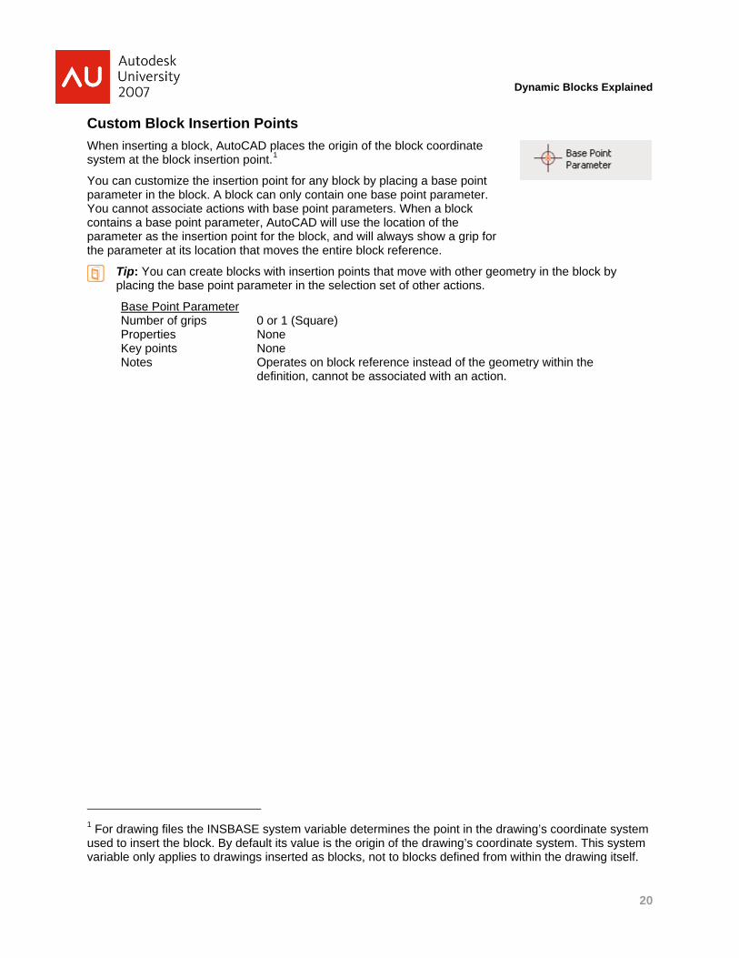
Custom Block Insertion Points When inserting a block, AutoCAD places the origin of the block coordinate system at the block insertion point.1
You can customize the insertion point for any block by placing a base point parameter in the block. A block can only contain one base point parameter. You cannot associate actions with base point parameters. When a block contains a base point parameter, AutoCAD will use the location of the parameter as the insertion point for the block, and will always show a grip for the parameter at its location that moves the entire block reference.
Tip: You can create blocks with insertion points that move with other geometry in the block by placing the base point parameter in the selection set of other actions.
Base Point Parameter
Number of grips 0 or 1 (Square) Properties None Key points None Notes Operates on block reference instead of the geometry within the
definition, cannot be associated with an action.
1 For drawing files the INSBASE system variable determines the point in the drawing’s coordinate system used to insert the block. By default its value is the origin of the drawing’s coordinate system. This system variable only applies to drawings inserted as blocks, not to blocks defined from within the drawing itself.
20

Using
CreatingYou can dspecial prvisibility pparametethe block.down mendisplayed
Notonly
When youvisibility senabled. Tchange thallow you visibility sthe Visibil
VisNumProKeyNot
Dynamic Blocks Expll
You mana
• Bdr
• B• B• B
an
Advance
g Blocks wdefine sets of roperty of the property and isr to the block When you clnu of the allow.
te: A block cay one visibility
u add a visibiltate controls These toolbahe current visi
to add or remtate. You canity States dia
ibility Parammber of grips
operties y points tes
age visibility s
VMODE toggraws entities VSHOW addVHIDE removVSTATE invond change th
ed Param
with Multipobjects in a bblock changes added to the. The visibilitylick this grip owed visibility
an only contaiy property or g
ity parameteron the Block r buttons andibility state in move objects n also managealog box (BVS
meter 0 or1 (VNonCanactio
states using th
gles on and ofnot in the curs entities to vves entities frokes the Bloceir order.
eters and
ple Views block that beces. This spece block wheny parameter aon a block refeproperty valu
in one visibilitgrip.
r to a block thEditor toolba controls allowthe Block Edfrom the curre visibility sta
STATE comm
r 1 (Inverted TVisibility state,ne nnot be assocon and a set
he following A
ff the visibilityrrent visibility visibility statesrom visibility sck Visibility Sta
d Actions
come invisibleial property is
n you add a vialso adds a trerence in a des (called vis
ty parameter,
he r are w you to itor and
rent ates using and).
Triangle) , text)
ciated with anof visibility sta
AutoCAD com
y of entities thstate with a d
s. states ates dialog, w
s
e when a s called a sibility iangular grip rawing, a dro
sibility states)
and hence,
action but deates.
mmands:
hat are not in tdimmed color
where you can
BVMODE
BVSHOW
BVHI
to op-
is
efines an imp
the current vir.
n add or remo
W
DE
BVSTATE
licit “visibility”
sibility. AutoC
ove visibility s
ained
21
Current visibility state
”
CAD
states
Dynamic Blocks Explained
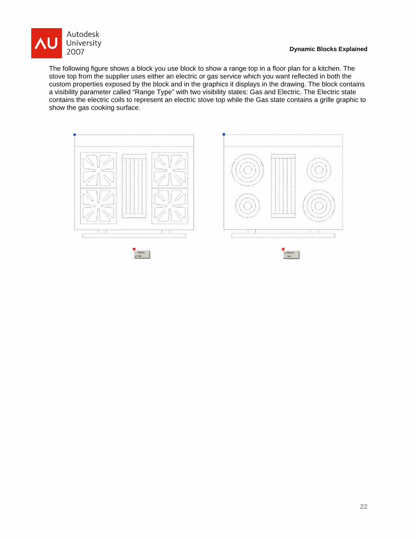
The following figure shows a block you use block to show a range top in a floor plan for a kitchen. The stove top from the supplier uses either an electric or gas service which you want reflected in both the custom properties exposed by the block and in the graphics it displays in the drawing. The block contains a visibility parameter called “Range Type” with two visibility states: Gas and Electric. The Electric state contains the electric coils to represent an electric stove top while the Gas state contains a grille graphic to show the gas cooking surface.
22
Dynamic Blocks Explained
Computing Custom Properties Using Lookup Tables You can add read-only properties to blocks that are computed from other block properties by adding lookup parameters and lookup tables to your dynamic block. For example you might add a “PartNumber” property whose value is determined by “looking up” the current “DoorWidth” and “DoorHeight” properties of your block in a table:
Door Width Door Height Part Number
30” 84” WD3084 36” 84” WD3684 30” 90” WD3690
Each lookup parameter adds a single read-only custom property and a triangular grip to the block definition. The Lookup property is a text string whose value is computed from the values of other properties in the block using a lookup table. The single, triangular grip added to the block definition does not display in a block reference when the underlying custom property is read-only. (Read-write lookup parameters are covered in the next section).
Lookup Parameter Number of grips 0 or 1 (Inverted Triangle) Properties 1 (Text) Key points None
Lookup actions define the spreadsheet-like tables that AutoCAD uses to compute the values of one or more lookup parameter properties from other parameter properties in the block. Lookup tables consist of input properties and lookup properties. When the value of an input property in the block changes AutoCAD “looks up” the new value in the table and finds the first row that matches the new property value. A row is only considered a match if all of the current values of the input properties match. When AutoCAD finds a match, it changes the Lookup property value to the corresponding value in the table. There is always a default row at the bottom of the table that AutoCAD uses if no match can be made.
Tip: Use lookup tables to compute one or more lookup properties when on one or more non-lookup properties change, or to set one or more non-lookup properties when a lookup property changes. AutoCAD uses the term “reverse lookup” when a change to a lookup parameter updates one or more non-lookup parameters.
Lookup Action Action Lookup property values in tables Association Associated with properties on one or more parameters Additional Data Updates properties in the block based on information from the table.
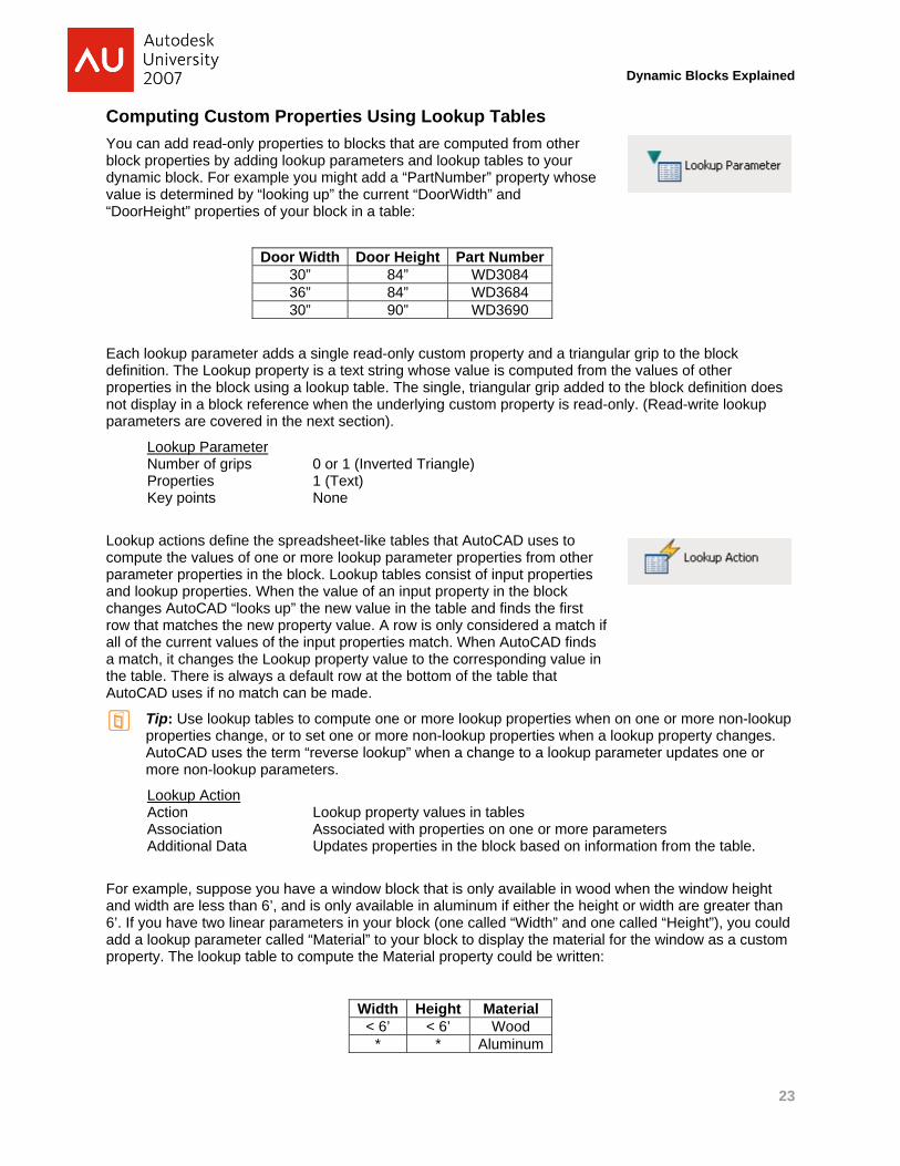
For example, suppose you have a window block that is only available in wood when the window height and width are less than 6’, and is only available in aluminum if either the height or width are greater than 6’. If you have two linear parameters in your block (one called “Width” and one called “Height”), you could add a lookup parameter called “Material” to your block to display the material for the window as a custom property. The lookup table to compute the Material property could be written:
Width Height Material < 6’ < 6’ Wood
* * Aluminum
23

Dynamic Blocks Explained
The row with the “*” values for Width and Height are used when no other matching row exists. Lookup tables in AutoCAD can match ranges of values for a particular property to one row, much like the “less than 6” mathematical notation above. The following rules apply when you specify lookup values in lookup tables:
• A lookup cell can contain a single value or multiple values
• Use a comma as the delimiter between values.
• You can specify any number of unique values separated by commas. For example: 5,6,7 5.5,6.25
• To specify a range, use brackets [ ] to specify that the range includes the values separated by a comma, or use parentheses ( ) to specify that the range does not include the values separated by a comma.
• For a continuous range, use a pair of values separated by a comma, enclosed in brackets or parentheses. For example: [3,10] specifies any value between 3 and 10, including 3 and 10 (3,10) specifies any value between 3 and 10, not including 3 and 10.
• For an open-ended range, use one value with a comma, enclosed in brackets or parentheses. For example: [,5] specifies less than or equal to 5; (5,) specifies greater than 5.
Using these rules the table above could also be written:
Width Height Material [,6) [,6) Wood [6,] [6,] Aluminum
24
Dynamic Blocks Explained
Setting Multiple Properties Using Reverse (Read-Write) Lookup Parameters Normally, lookup parameters are read-only block properties whose values are computed from other custom properties in the block, called input properties, by looking up the current values of the input properties and finding the matching row in the table.
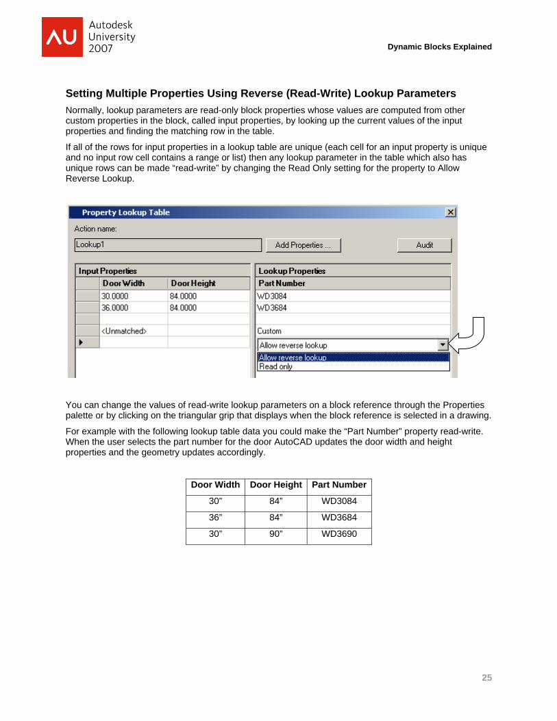
If all of the rows for input properties in a lookup table are unique (each cell for an input property is unique and no input row cell contains a range or list) then any lookup parameter in the table which also has unique rows can be made “read-write” by changing the Read Only setting for the property to Allow Reverse Lookup.
You can change the values of read-write lookup parameters on a block reference through the Properties palette or by clicking on the triangular grip that displays when the block reference is selected in a drawing.
For example with the following lookup table data you could make the “Part Number” property read-write. When the user selects the part number for the door AutoCAD updates the door width and height properties and the geometry updates accordingly.
Door Width Door Height Part Number
30” 84” WD3084
36” 84” WD3684
30” 90” WD3690
25
Dynamic Blocks Explained
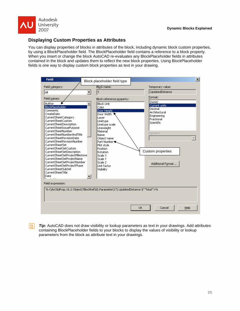
Displaying Custom Properties as Attributes You can display properties of blocks in attributes of the block, including dynamic block custom properties, by using a BlockPlaceholder field. The BlockPlaceholder field contains a reference to a block property. When you insert or change the block AutoCAD re-evaluates any BlockPlaceholder fields in attributes contained in the block and updates them to reflect the new block properties. Using BlockPlaceholder fields is one way to display custom block properties as text in your drawing.
Block placeholder field type
Tip: AutoCAD does not draw visibility or lookup parameters as text in your drawings. Add attributes containing BlockPlaceholder fields to your blocks to display the values of visibility or lookup parameters from the block as attribute text in your drawings.
Custom properties
26
Dynamic Blocks Explained
Avoiding Pitfalls: Understanding How Parameters and Actions Work
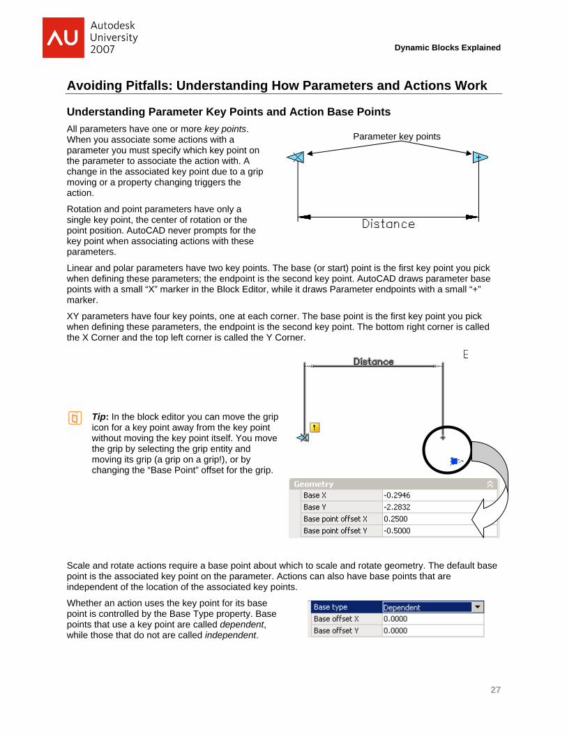
Understanding Parameter Key Points and Action Base Points All parameters have one or more key points. When you associate some actions with a parameter you must specify which key point on the parameter to associate the action with. A change in the associated key point due to a grip moving or a property changing triggers the action.
Rotation and point parameters have only a single key point, the center of rotation or the point position. AutoCAD never prompts for the key point when associating actions with these parameters.
Linear and polar parameters have two key points. The base (or start) point is the first key point you pick when defining these parameters; the endpoint is the second key point. AutoCAD draws parameter base points with a small “X” marker in the Block Editor, while it draws Parameter endpoints with a small “+” marker.
XY parameters have four key points, one at each corner. The base point is the first key point you pick when defining these parameters, the endpoint is the second key point. The bottom right corner is called the X Corner and the top left corner is called the Y Corner.
Tip: In the block editor you can move the grip icon for a key point away from the key point without moving the key point itself. You move the grip by selecting the grip entity and moving its grip (a grip on a grip!), or by changing the “Base Point” offset for the grip.
Parameter key points
Scale and rotate actions require a base point about which to scale and rotate geometry. The default base point is the associated key point on the parameter. Actions can also have base points that are independent of the location of the associated key points.
Whether an action uses the key point for its base point is controlled by the Base Type property. Base points that use a key point are called dependent, while those that do not are called independent.
27
Dynamic Blocks Explained
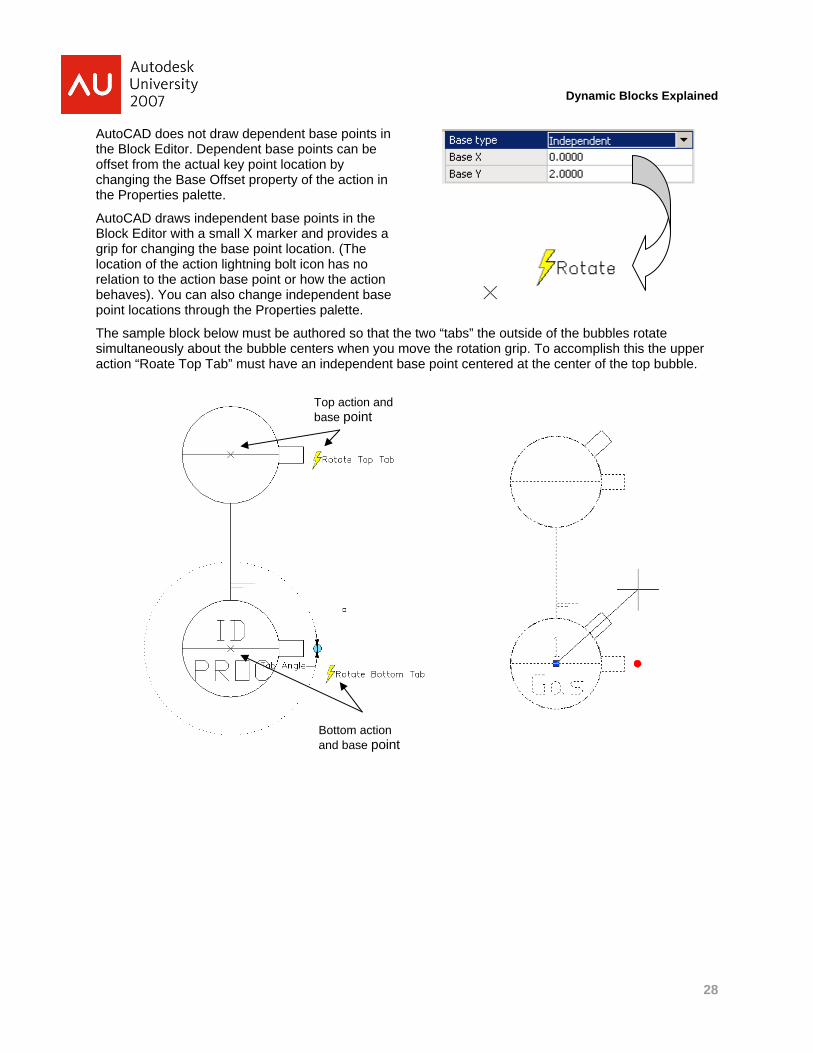
AutoCAD does not draw dependent base points in the Block Editor. Dependent base points can be offset from the actual key point location by changing the Base Offset property of the action in the Properties palette.
AutoCAD draws independent base points in the Block Editor with a small X marker and provides a grip for changing the base point location. (The location of the action lightning bolt icon has no relation to the action base point or how the action behaves). You can also change independent base point locations through the Properties palette.
The sample block below must be authored so that the two “tabs” the outside of the bubbles rotate simultaneously about the bubble centers when you move the rotation grip. To accomplish this the upper action “Roate Top Tab” must have an independent base point centered at the center of the top bubble.
Top action and base point
Bottom action and base point
28
Dynamic Blocks Explained
Understanding Order Dependencies: Moving Parameters or Actions with Actions You can move parameters and other actions in a dynamic block just like other geometry by including them in the selection set of objects when you define an action. Parameters can move, rotate, stretch, scale and flip when they are in an action’s selection set. Independent base points on actions can move, rotate, stretch, scale and flip when the actions are in a selection set. Angle offsets on actions can rotate and flip when the actions are in a selection set.
For example, suppose you have a linear parameter that stretches some geometry in your block. Suppose you have a rotation parameter and a rotate action that rotates the geometry about some fixed point. By including the linear parameter and its stretch action in the rotate action’s selection set, you can rotate the linear parameter and its grips right along with the rest of the geometry.
Associated actions are not triggered when a parameter’s key point or other properties (e.g., distance properties) change as a result of being in an action’s selection set.
You may not get the expected behavior when an action operates on other actions or parameters, depending on the objects in an action’s selection set. Unexpected behavior typically occurs when two or more actions operate on the same geometry, but you did not include the other actions and parameters in the selection set.
In many cases, this leads to blocks whose appearance depends on the order in which they are modified. We call blocks that have the same properties but different appearances order dependent blocks.
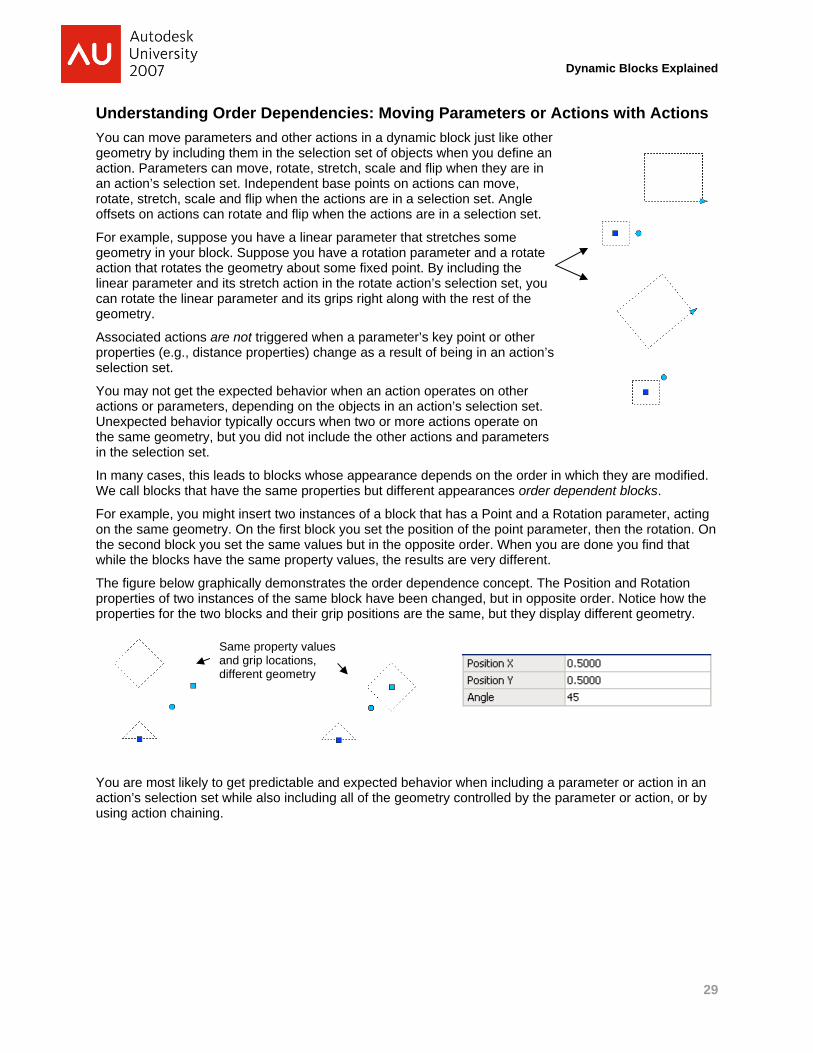
For example, you might insert two instances of a block that has a Point and a Rotation parameter, acting on the same geometry. On the first block you set the position of the point parameter, then the rotation. On the second block you set the same values but in the opposite order. When you are done you find that while the blocks have the same property values, the results are very different.
The figure below graphically demonstrates the order dependence concept. The Position and Rotation properties of two instances of the same block have been changed, but in opposite order. Notice how the properties for the two blocks and their grip positions are the same, but they display different geometry.
Same property values and grip locations, different geometry
You are most likely to get predictable and expected behavior when including a parameter or action in an action’s selection set while also including all of the geometry controlled by the parameter or action, or by using action chaining.
29
Dynamic Blocks Explained
Using Action Chaining to Trigger Actions on Other Parameters Normally, actions are only triggered when a user directly manipulates a grip or property on the block. They are normally not triggered when an action moves, rotates, scales, or stretches the parameters and key points on which other actions depend. There are times when it is desirable to trigger actions dependent on a parameter when the parameter moves, stretches, or rotates as the result of another action.
AutoCAD uses the term chaining to describe whether AutoCAD triggers actions on a parameter when the parameter changes as the result of another action. AutoCAD disables chaining by default, but you can set the Chain Actions property by selecting a Parameter in the Block Editor and changing the property in the Properties palette. The chaining setting applies to all actions associated with the parameter.
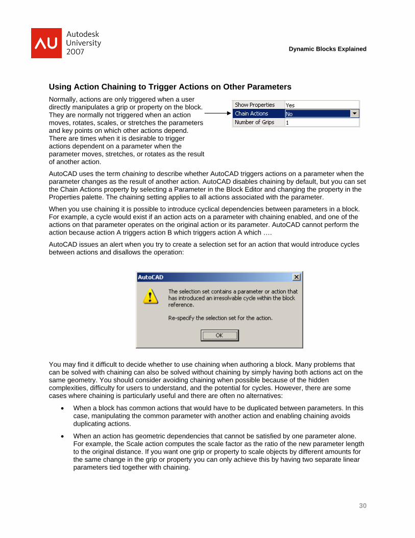
When you use chaining it is possible to introduce cyclical dependencies between parameters in a block. For example, a cycle would exist if an action acts on a parameter with chaining enabled, and one of the actions on that parameter operates on the original action or its parameter. AutoCAD cannot perform the action because action A triggers action B which triggers action A which ….
AutoCAD issues an alert when you try to create a selection set for an action that would introduce cycles between actions and disallows the operation:
You may find it difficult to decide whether to use chaining when authoring a block. Many problems that can be solved with chaining can also be solved without chaining by simply having both actions act on the same geometry. You should consider avoiding chaining when possible because of the hidden complexities, difficulty for users to understand, and the potential for cycles. However, there are some cases where chaining is particularly useful and there are often no alternatives:
• When a block has common actions that would have to be duplicated between parameters. In this case, manipulating the common parameter with another action and enabling chaining avoids duplicating actions.
• When an action has geometric dependencies that cannot be satisfied by one parameter alone. For example, the Scale action computes the scale factor as the ratio of the new parameter length to the original distance. If you want one grip or property to scale objects by different amounts for the same change in the grip or property you can only achieve this by having two separate linear parameters tied together with chaining.
30
Dynamic Blocks Explained
Working with Dynamic Blocks in Custom Applications
Understanding Anonymous Blocks and how Dynamic Blocks Affect Drawing Size Dynamic blocks generally require slightly more drawing space than non-dynamic blocks for the same number of distinct blocks required for the drawing. This overhead comes from the space required to store the actions and parameters that constitute the dynamic block, and to store the custom property values on each copy of a dynamic block reference inserted into the drawing. Generally speaking, this overhead will be minimal compared to the typical overall drawing size, or even to the space required for the geometry in the block itself.
When you modify a dynamic block reference’s grips or properties so that its geometry differs from the original block definition, AutoCAD creates an anonymous block containing the correct geometry and adds it to the drawing. Anonymous block names start with “*U” followed by a unique number. Anonymous blocks are not visible in the user interface and you cannot normally insert or edit them2. AutoCAD optimizes the use of anonymous blocks: if two block references in your drawing need the same geometry, AutoCAD creates one anonymous block and shares it between the references. AutoCAD purges unused anonymous blocks automatically when you save and re-open a drawing, or you can purge them yourself using the PURGE command.
The way you author dynamic blocks can also affect the size of your drawing. In many cases the same behavior can be achieved many different ways. Some approaches have a reduced impact on drawing size while others can lead to bloat. In some cases you may need to compromise of ease of maintenance or slightly different behavior in a block to reduce the impact on drawing size. Which tradeoffs you value will determine what kind of blocks you author.
If you are concerned about drawing size keep the following in mind when authoring blocks:
• Blocks with chaining or order-dependencies require AutoCAD to maintain a history of each operation performed on each block reference. AutoCAD retains the history for the life of the block reference until either the reference is reset or you modify the block so that a history is no longer required. For most blocks the space required for the history is small compared to the overall drawing size, but blocks with different history will never “share” an anonymous block. This can lead to drawing bloat as the number of anonymous blocks increases, assuming two blocks rarely have matching histories.
• Blocks containing many objects can lead to unnecessary drawing bloat when only a few of the objects change from instance to instance. Consider the example of a block containing a complex schematic of a part, where the block exposes only a single to reposition a single entity within the block. When AutoCAD creates an anonymous block it copies all of the block’s objects into the anonymous block even if some of the objects are unchanged by any actions from the original block definition. This often occurs when a block contains a single visibility parameter to manage some highly detailed block geometry, or when you apply single actions to large numbers of objects in a block. If drawing space is important consider using nested blocks to reduce drawing bloat: replace the “common” entities in your dynamic block with references to blocks containing the entities. This approach gains efficiency in drawing size at the expense of block library complexity since your library and drawings require multiple (nested) block definitions to support a single dynamic block definition.
2 AutoCAD exposes anonymous blocks through various programming interfaces to applications. Custom applications may expose anonymous blocks directly to the user.
31
Dynamic Blocks Explained
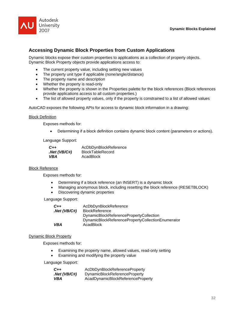
Accessing Dynamic Block Properties from Custom Applications Dynamic blocks expose their custom properties to applications as a collection of property objects. Dynamic Block Property objects provide applications access to:
• The current property value, including setting new values • The property unit type if applicable (none/angle/distance) • The property name and description • Whether the property is read-only • Whether the property is shown in the Properties palette for the block references (Block references
provide applications access to all custom properties.) • The list of allowed property values, only if the property is constrained to a list of allowed values
AutoCAD exposes the following APIs for access to dynamic block information in a drawing: Block Definition
Exposes methods for:
• Determining if a block definition contains dynamic block content (parameters or actions).
Language Support:
C++ AcDbDynBlockReference .Net (VB/C#) BlockTableRecord VBA AcadBlock
Block Reference
Exposes methods for:
• Determining if a block reference (an INSERT) is a dynamic block • Managing anonymous block, including resetting the block reference (RESETBLOCK) • Discovering dynamic properties
Language Support:
C++ AcDbDynBlockReference .Net (VB/C#) BlockReference
DynamicBlockReferencePropertyCollection DynamicBlockReferencePropertyCollectionEnumerator
VBA AcadBlock
Dynamic Block Property
Exposes methods for:
• Examining the property name, allowed values, read-only setting • Examining and modifying the property value
Language Support:
C++ AcDbDynBlockReferenceProperty .Net (VB/C#) DynamicBlockReferenceProperty VBA AcadDynamicBlockReferenceProperty
32
Dynamic Blocks Explained
Legacy Application Compatibility and Dynamic Blocks Many custom applications extract information from block references in drawings, for example to count blocks or to extract detailed information stored in block attributes. Many of these applications use the name of the referenced block to limit the search or to filter and organize the results. For example an application might count the number of reference to a block with a particular name.
When you modify a dynamic block reference’s grips or properties so that its geometry differs from the original block definition, AutoCAD creates an anonymous block containing the correct geometry and adds it to the drawing. Anonymous block names start with “*U” followed by a unique number.
You may need to update your legacy applications to work with dynamic blocks because of the way AutoCAD manages the anonymous blocks used to draw dynamic blocks. To existing applications, a modified dynamic block which references an anonymous block looks like an anonymous block, not like the block you inserted to create the reference.
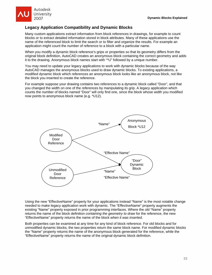
For example suppose your drawing contains two references to a dynamic block called “Door”, and that you changed the width on one of the references by manipulating its grip. A legacy application which counts the number of blocks named “Door” will only find one, since the block whose width you modified now points to anonymous block name (e.g. *U12).
Unmodified Door
Reference
“Door” Dynamic
Block
Anonymous
Block *U12 “Name”
“Effective Name”
“Name”
“Effective Name”
Modified Door
Reference
Using the new “EffectiveName” property for your applications instead “Name” is the most notable change needed to make legacy application work with dynamic. The “EffectiveName” property augments the existing “Name” property exposed in prior programming interfaces. Where the old “Name” property returns the name of the block definition containing the geometry to draw for the reference, the new “EffectiveName” property returns the name of the block when it was inserted.
Both properties can be examined at any time for any kind of block reference. For old blocks and for unmodified dynamic blocks, the two properties return the same block name. For modified dynamic blocks the “Name” property returns the name of the anonymous block generated for the reference, while the “EffectiveName” property returns the name of the original dynamic block definition.
33
Dynamic Blocks Explained
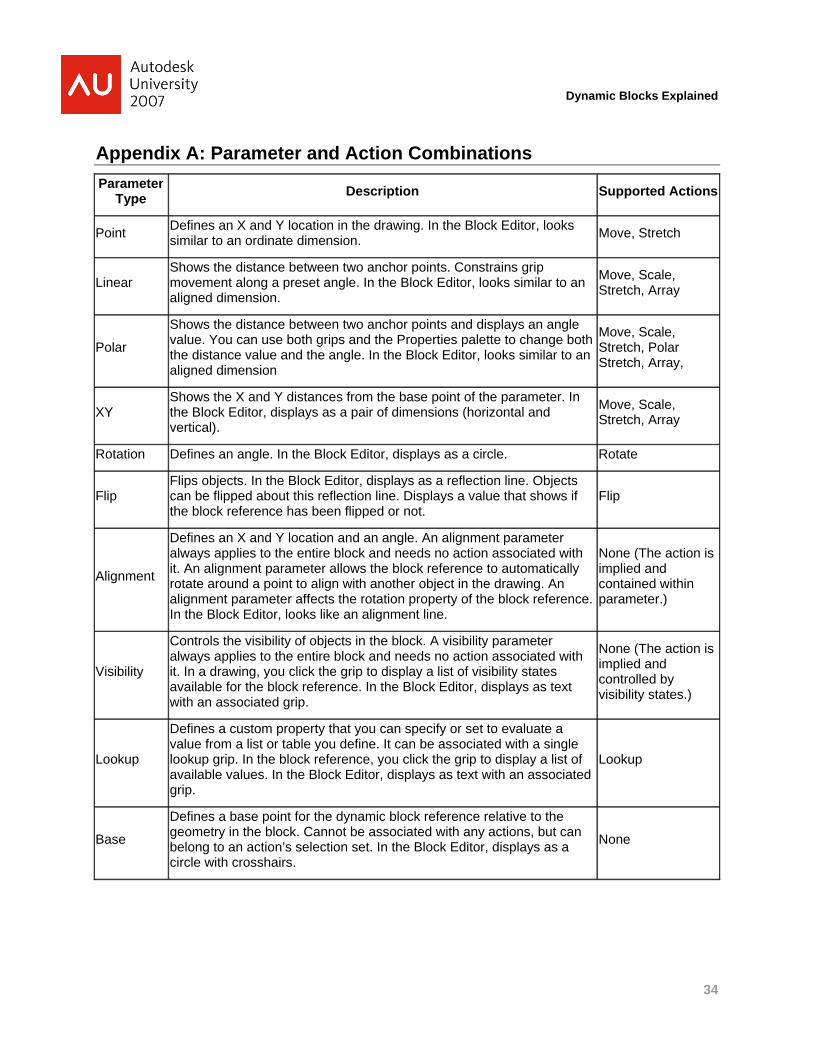
Appendix A: Parameter and Action Combinations Parameter
Type Description Supported Actions
Point Defines an X and Y location in the drawing. In the Block Editor, looks similar to an ordinate dimension. Move, Stretch
Linear Shows the distance between two anchor points. Constrains grip movement along a preset angle. In the Block Editor, looks similar to an aligned dimension.
Move, Scale, Stretch, Array
Polar
Shows the distance between two anchor points and displays an angle value. You can use both grips and the Properties palette to change both the distance value and the angle. In the Block Editor, looks similar to an aligned dimension
Move, Scale, Stretch, Polar Stretch, Array,
XY Shows the X and Y distances from the base point of the parameter. In the Block Editor, displays as a pair of dimensions (horizontal and vertical).
Move, Scale, Stretch, Array
Rotation Defines an angle. In the Block Editor, displays as a circle. Rotate
Flip Flips objects. In the Block Editor, displays as a reflection line. Objects can be flipped about this reflection line. Displays a value that shows if the block reference has been flipped or not.
Flip
Alignment
Defines an X and Y location and an angle. An alignment parameter always applies to the entire block and needs no action associated with it. An alignment parameter allows the block reference to automatically rotate around a point to align with another object in the drawing. An alignment parameter affects the rotation property of the block reference. In the Block Editor, looks like an alignment line.
None (The action is implied and contained within parameter.)
Visibility
Controls the visibility of objects in the block. A visibility parameter always applies to the entire block and needs no action associated with it. In a drawing, you click the grip to display a list of visibility states available for the block reference. In the Block Editor, displays as text with an associated grip.
None (The action is implied and controlled by visibility states.)
Lookup
Defines a custom property that you can specify or set to evaluate a value from a list or table you define. It can be associated with a single lookup grip. In the block reference, you click the grip to display a list of available values. In the Block Editor, displays as text with an associated grip.
Lookup
Base
Defines a base point for the dynamic block reference relative to the geometry in the block. Cannot be associated with any actions, but can belong to an action’s selection set. In the Block Editor, displays as a circle with crosshairs.
None
34
Dynamic Blocks Explained
35
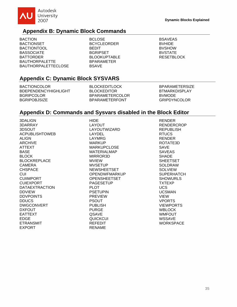
Appendix B: Dynamic Block Commands BACTION BACTIONSET BACTIONTOOL BASSOCIATE BATTORDER BAUTHORPALETTE BAUTHORPALETTECLOSE
BCLOSE BCYCLEORDER BEDIT BGRIPSET BLOOKUPTABLE BPARAMETER BSAVE
BSAVEAS BVHIDE BVSHOW BVSTATE RESETBLOCK
Appendix C: Dynamic Block SYSVARS BACTIONCOLOR BDEPENDENCYHIGHLIGHT BGRIPCOLOR BGRIPOBJSIZE
BLOCKEDITLOCK BLOCKEDITOR BPARAMETERCOLOR BPARAMETERFONT
BPARAMETERSIZE BTMARKDISPLAY BVMODE GRIPDYNCOLOR
Appendix D: Commands and Sysvars disabled in the Block Editor 3DALIGN 3DARRAY 3DSOUT ACPUBLISHTOWEB ALIGN ARCHIVE ATTEXT BASE BLOCK BLOCKREPLACE CAMERA CHSPACE CUI CUIIMPORT CUIEXPORT DATAEXTRACTION DDVIEW DDVPOINTS DDUCS DWGCONVERT DXFOUT EATTEXT EDGE ETRANSMIT EXPORT
HIDE LAYOUT LAYOUTWIZARD LAYDEL LAYMRG MARKUP MARKUPCLOSE MATERIALMAP MIRROR3D MVIEW MVSETUP NEWSHEETSET OPENDWFMARKUP OPENSHEETSET PAGESETUP PLOT PSETUPIN PREVIEW PSOUT PUBLISH PURGE QSAVE QUICKCUI REFEDIT RENAME
RENDER RENDERCROP REPUBLISH RTUCS RENDER ROTATE3D SAVE SAVEAS SHADE SHEETSET SOLDRAW SOLVIEW SUPERHATCH SHOWURLS TXTEXP UCS UCSMAN VIEW VPORTS VIEWPORTS WBLOCK WMFOUT WSSAVE WORKSPACE