dynamic analysis of a rotor-journal bearing system of
TRANSCRIPT
Purdue UniversityPurdue e-Pubs
International Compressor Engineering Conference School of Mechanical Engineering
2006
Dynamic Analysis of a Rotor-Journal BearingSystem of Rotary CompressorFei XieXi’an Jiaotong University
Haifeng ZhangXi’an Jiaotong University
Jianhua WuXi’an Jiaotong University
Wenjing MaXi’an Jiaotong University
Chunhui LiuShanghai Hitachi Electrical Appliances Co.
See next page for additional authors
Follow this and additional works at: https://docs.lib.purdue.edu/icec
This document has been made available through Purdue e-Pubs, a service of the Purdue University Libraries. Please contact [email protected] foradditional information.Complete proceedings may be acquired in print and on CD-ROM directly from the Ray W. Herrick Laboratories at https://engineering.purdue.edu/Herrick/Events/orderlit.html
Xie, Fei; Zhang, Haifeng; Wu, Jianhua; Ma, Wenjing; Liu, Chunhui; and Gae, Xiaojun, "Dynamic Analysis of a Rotor-Journal BearingSystem of Rotary Compressor" (2006). International Compressor Engineering Conference. Paper 1820.https://docs.lib.purdue.edu/icec/1820

AuthorsFei Xie, Haifeng Zhang, Jianhua Wu, Wenjing Ma, Chunhui Liu, and Xiaojun Gae
This article is available at Purdue e-Pubs: https://docs.lib.purdue.edu/icec/1820

C036, Page 1
International Compressor Engineering Conference at Purdue, July 17-20, 2006
Dynamic Analysis of a Rotor-Journal Bearing System
of Rotary Compressor
Fei Xie1, Haifeng Zhang1, Jianhua Wu1, Wenjing Ma1 Chunhui Liu2, Xiaojun Gao2
1Xi’an Jiaotong University, Xi’an, P.R.China
E-mail: [email protected]
2 Shanghai Hitachi Electrical Appliances Co., Ltd., Shanghai, P.R.China
ABSTRACT With the development of the rotary compressor which is arming at inverter control, large capacity and new
refrigerants, the flexibility of rotor and bearing housings more seriously influences reliability of the rotor-journal bearing system. In order to avoid the slanting abrasion of bearings and restrict the center locus of the motor rotor top, the system is numerically solved as a dynamic nonlinear fluid-structure interaction problem in this paper. The finite element models of the rotor and bearing housings are built up by using the Timoshenko beam model. The Reynolds equation is solved by variational principle, and the finite element method is used to discretize the oil film. An iterative method based on the complimentary principle is used to solve the oil film force and the Reynolds boundary simultaneously. The governing equations are solved by Newton-Raphson method. Because the flexibility of the system and its influence on the oil film are considered, we can accurately estimate the reliability and optimize the structure of the system. The analyzed results for different rotational speeds are described.
1. INTRODUCTION The rotor-journal bearing system for a rotary compressor is a flexible nonlinear system. As shown in Figure 1,
the rotor, which includes the shaft(labeled ③), motor rotor and balance weights, composes the rotor-journal bearing
system with bearing housings(main bearing housing labeled ① and sub bearing housing labeled ②). The flexibility of the rotor and the bearing housings influence seriously the reliability of the rotor-journal bearing system.
The diameter of the shaft is limited by the structure, the eccentric part of shaft bears the action of large gas force that changes over a wide range, and the part of motor rotor is cantilevered. These characteristics make bearing load relatively large and the deformation of the shaft is also large. If the rotor-journal bearing system is designed improperly, seriously slanting abrasion will occur at the bearings (shown as b in Figure 1), and contact between motor rotor and motor stator will occur at the rotor top (shown as a in Figure 1). These will reduce the reliability of the compressor greatly. For the new designed compressor with inverter control, large capacity and new refrigerant which meets the present demand of the market, the loads of the rotor-journal bearing system are becoming larger and larger, so the reliability problem is becoming more serious.
The oil film force is the mainly nonlinear factor in this system. In the early study, the oil film force had once been solved by the short bearing theory, Holland method and etc. The width-diameter ratio of the bearings is between 0.25 and 4, so it is improper to apply short bearing or long bearing theory; The oil film thickness is influenced by the deformation of the bearing and shaft, so it is also improper to apply Holland or Hahn method for finite bearing.
C036, Page 2
International Compressor Engineering Conference at Purdue, July 17-20, 2006
In this study, in order to estimate the reliability of the rotor-journal system and ensure its reliability by optimum design of the rotor and bearings, the method has been built up to take consideration of the flexibility of the system and its influence on the oil film thickness.
2. THE GOVERNING EQUATIONS
2.1 the Finite Element Model of the Rotor and Bearings The rotor-journal system of the rotary compressor bears the action of larger transverse external force, has a
little mass and little bearing clearance, and hasn’t enough high speed as the turbine machine. Therefore, inertia force is so smaller than gas force ( )gF θ . Ignoring inertia force (not including inertia force of balance weight and eccentric mass) and damping force, we build up the following equations.
[ ]{ } { } { } { }( ){ }( ) ,g oK q F F q qθ= + (1)
where { }q is vector of displacement, { }q is vector of velocity, { } { }, , ,T
y zq y z θ θ= , ( )gF θ is gas force and
{ } { }( ),oF q q is oil film force, θ is the rotational angle of the rotor.
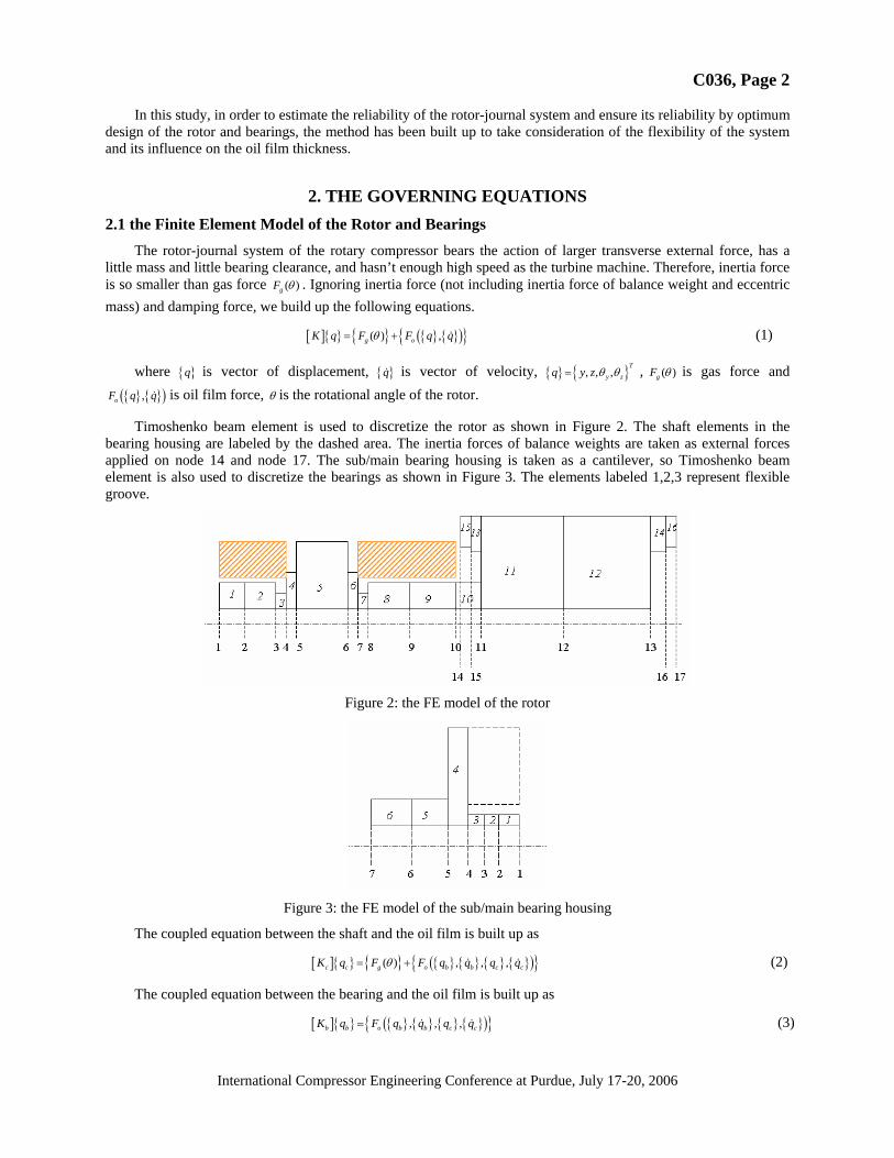
Timoshenko beam element is used to discretize the rotor as shown in Figure 2. The shaft elements in the bearing housing are labeled by the dashed area. The inertia forces of balance weights are taken as external forces applied on node 14 and node 17. The sub/main bearing housing is taken as a cantilever, so Timoshenko beam element is also used to discretize the bearings as shown in Figure 3. The elements labeled 1,2,3 represent flexible groove.
Figure 2: the FE model of the rotor
Figure 3: the FE model of the sub/main bearing housing
The coupled equation between the shaft and the oil film is built up as
[ ]{ } { } { } { } { } { }( ){ }( ) , , ,c c g o b b c cK q F F q q q qθ= + (2)
The coupled equation between the bearing and the oil film is built up as
[ ]{ } { } { } { } { }( ){ }, , ,b b o b b c cK q F q q q q= (3)

C036, Page 3
International Compressor Engineering Conference at Purdue, July 17-20, 2006
The subscript c represents rotor, and the subscript b represents bearing housing. 2.2 the Finite Element Model of Oil Film
The sectional view of the journal bearing is shown in Figure 4, which depicts the position of the journal in the bearing at any moment. The thickness of the oil film at this moment can be expressed as follows,
( , ) [ ( )sin ( )cos ]j b b jh z C x x y yθ θ θ= + − + − (4)
where C is clearance, ( , )j jx y the coordinate of the shaft journal’s center jO , ( , )b bx y the coordinate of the bearing housing’s center bO . The Reynolds equation is expressed as follows.
3 32
1 6 12P P hh h hz zθ θ λ θ
∂ ⎛ ∂ ⎞ ∂ ⎛ ∂ ⎞ ∂+ = +⎜ ⎟ ⎜ ⎟∂ ∂ ∂ ∂ ∂⎝ ⎠ ⎝ ⎠
(5)
As shown in Figure 5, the bilinear four-node rectangle element is used to discretize the oil film, and Reynolds Boundary Condition is written as Eq. (6), where cΓ is undetermined boundary between the domain H + ( 0)P > and
0H ( 0)P = .
1
2
: 1 0: 1 0
: undetermined 0, 0c
z Pz P
P Pn
⎧⎪ Γ = + =⎪⎪ Γ = − =⎨⎪ ∂⎪Γ = =⎪ ∂⎩
(6)
Based on the variational principle, Solution of this problem can be equivalent to solution of the variational problem which is expressed as Eq. (7). That is, the weak solution of the Reynolds equation is the value of P which make ( )J P reach the minimum in the domain H + . The domain H + is subset of the whole domain H .
2 23*
21( ) min ( ) min
2P H P H
h P PJ P J P PF dzθ λ+ + Ω∈ ∈
⎧ ⎫⎡ ⎤⎛ ∂ ⎞ ⎛ ∂ ⎞⎪ ⎪= = + − Ω⎢ ⎥⎨ ⎬⎜ ⎟ ⎜ ⎟∂ ∂⎝ ⎠ ⎝ ⎠⎢ ⎥⎪ ⎪⎣ ⎦⎩ ⎭∫∫ (7)
Appling the finite element method to approximate the solution of Eq. (7), we can obtain Eq. (8).
[ ]{ } { } 0,K P F P H +− = ∈ (8)
In order to convert the solution domain from H + to H , we apply complementary principle to construct Eq. (9) by introducing complementary parameter e .
[ ]{ } { } { }
{ } { } 0T
K P F e
P e
⎧ − =⎪⎨
=⎪⎩ (9)
Then solve P which satisfies 0, 0P e≥ ≥ in the whole domain H . Using special iterative algorithm, we make convergence speed much faster.
To analyze the periodic motions of rotor dynamic system, the Jacobian matrix with respect to the location and velocity of journal will be needed. Therefore, the pressure distribution in point “1”, which is the function of location and velocity of journal at any moment, is expanded in a Taylor series in the neighbor point “0”, and only the linear term is retained, namely
0 100 200 300-1
-0.5
0
0.5
1
0P = cΓ
2Γ θ
z cΓ
1Γ
0P >
Figure 4: Sectional view of the journal bearing Figure 5: Expanded schematic diagram of oil film

C036, Page 4
International Compressor Engineering Conference at Purdue, July 17-20, 2006
1 0 0 0 0 0| |j j j jx y x yP P P x P y P x P y= + Δ + Δ + Δ + Δ (10)
So we can derive the jacobian matrix as Eq. (11), and solve it with the Reynolds equation simultaneously in the same way. In Eq. (11), the slant of shaft and the deformation of the bearing housings can be considered.
3 3 3 32 2
3 3 32
1 3sin sin sin 3 sin6 cos 3 36
1 3cos cos6 sin 3
j j
j j
x x
y y
P P h P Ph h h h hz z h h h z z h
P P h Ph h hz z h
θ θ θ θθθ θ λ θ θ θ λ
θθθ θ λ θ θ θ
⎛ ∂ ⎞ ⎛ ∂ ⎞ ⎛ ⎞∂ ∂ ∂ ∂ ∂ ∂ ∂⎛ ⎞ ⎛ ⎞+ = − − − −⎜ ⎟ ⎜ ⎟ ⎜ ⎟ ⎜ ⎟ ⎜ ⎟⎜ ⎟ ⎜ ⎟∂ ∂ ∂ ∂ ∂ ∂ ∂ ∂ ∂⎝ ⎠ ⎝ ⎠⎝ ⎠⎝ ⎠ ⎝ ⎠⎛ ∂ ⎞ ⎛ ∂ ⎞ ⎛ ⎞∂ ∂ ∂ ∂ ∂
+ = + +⎜ ⎟ ⎜ ⎟ ⎜ ⎟⎜ ⎟ ⎜ ⎟∂ ∂ ∂ ∂ ∂ ∂ ∂⎝ ⎠⎝ ⎠ ⎝ ⎠
32
3 32
3 32
cos 3 cos36
1 12sin
1 12cos
j j
j j
x x
y y
Ph hh h z z h
P Ph h
z z
P Ph h
z z
θ θ θλ
θθ θ λ
θθ θ λ
⎧⎪⎪⎪⎪ ∂ ∂⎛ ⎞ ⎛ ⎞+ +⎪ ⎜ ⎟ ⎜ ⎟∂ ∂⎝ ⎠ ⎝ ⎠⎪⎨
⎛ ∂ ⎞ ⎛ ∂ ⎞⎪ ∂ ∂+ =⎜ ⎟ ⎜ ⎟⎪ ⎜ ⎟ ⎜ ⎟∂ ∂ ∂ ∂⎪ ⎝ ⎠ ⎝ ⎠
⎪ ⎛ ∂ ⎞ ⎛ ∂ ⎞∂ ∂⎪ + = −⎜ ⎟ ⎜ ⎟⎪ ⎜ ⎟ ⎜ ⎟∂ ∂ ∂ ∂⎝ ⎠ ⎝ ⎠⎩
(11)
3. COUPLED METHOD 3.1 the Coupled Method between Rotor and Oil Film
The oil film force is mainly nonlinear factor. The node, which is acted by oil film force, is called nonlinear node, another node is called linear node. For this system with local non-linearity, its governing equation Eq. (2) can be written as follows
111 12 1
221 22 2
0g
g o
FK K qF FK K q
⎧ ⎫ ⎧ ⎫⎡ ⎤ ⎧ ⎫ ⎪ ⎪= +⎨ ⎬ ⎨ ⎬ ⎨ ⎬⎢ ⎥⎪ ⎪⎣ ⎦ ⎩ ⎭ ⎩ ⎭⎩ ⎭
(12)
where { }1q are the degrees of freedom on the linear nodes, { }2q are the degrees of freedom on the nonlinear nodes. gF is the gas force. oF is the oil film force. We can obtain
{ }11 11 1 12 2gq K F K q−= − (13)
2 2ˆˆ
g oKq F F f= + + (14)
where 1
22 21 11 12
121 11 1
ˆ
ˆg
K K K K K
f K K F
−
−
= −
= −
Eq. (14) is a set of nonlinear algebraic equations, matrix K̂ is constant at a certain rotational speed for the system studied in this paper, 2gF and f̂ are the functions of time, whereas oF is the function of { }q and { }q . { }q is assumed to be known, then { }q can be solved by Newton-Raphson method. Through the value of { }q , we can get { }q in the next time. In this way we can get the value of { }q and { }q at every moment.
The Newton-Raphson method is presented as follows.
[ ] { }y
z
yz
D Fθθ
Δ⎧ ⎫⎪ ⎪Δ⎪ ⎪ =⎨ ⎬Δ⎪ ⎪⎪ ⎪Δ⎩ ⎭
(15)
where
[ ] { }{ }
{ }{ }
[ ] { }2 2
2 2ˆˆ
o
X
ig o
F FD
q
F K q F F f
θ⎡ ⎤∂ ∂
= −⎢ ⎥∂ ∂⎢ ⎥⎣ ⎦
= − + + +

C036, Page 5
International Compressor Engineering Conference at Purdue, July 17-20, 2006
{ }
{ }2 2 2
2 2 2
TX
T
y z
q y z
θ θ θ
=
=
and 12 2 21
2 2 2
i i iX X Xi i i
q q qθ θ θ
+
+
⎧ ⎫ ⎧ ⎫ ⎧ ⎫Δ⎪ ⎪ ⎪ ⎪ ⎪ ⎪= +⎨ ⎬ ⎨ ⎬ ⎨ ⎬Δ⎪ ⎪ ⎪ ⎪ ⎪ ⎪⎩ ⎭ ⎩ ⎭ ⎩ ⎭
in fact, { }{ }2
o
X
Fq
⎡ ⎤∂⎢ ⎥∂⎢ ⎥⎣ ⎦
is the Jacobian matrix of the oil film force with respect to the translational velocity of journal.
3.2 the Coupled Method between Bearing housing and Oil Film Firstly, we assume that the deformation of the bearing housing is known in a certain moment. Secondly, the oil
film force and the deformation of shaft are obtained by solving the Eq. (2). Then substituting the oil film force into Eq. (3), the deformation of bearing housing can be updated. The center’s velocity of the bearing housing can be obtained as
1t tb b
bq qq
t
−−=
Δ. (16)
4. SIMULATION RESULTS AND DISCUSSIONS According to the method mentioned above, the rotor-journal system of the single rotary compressor has been
investigated in detail. Figure 6 to Figure 12 show the analyzed results for the rotational speed of 3450 rpm and 7200 rpm.
Figure 6 shows the gas force, sub bearing oil film force and main bearing oil film force on shaft. The flexibility of shaft and the difference of widths between main bearing and sub bearing produce the difference of oil film forces of main bearing and sub bearing on shaft. However the difference at speed of 3450 is no big for the single cylinder rotary compressor analyzed, and the difference at speed of 7200 become larger.
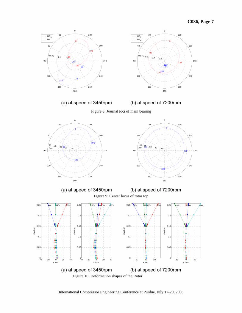
The journal loci of the sub and main bearing at two ends (the situation at the bottom end close to the cylinder represented by subscript b and that at the top of the bearing housing represented by subscript t) are shown in Figure 7 and Figure 8. Based on the loci, we can find that the oil film thickness at bottom of sub bearing housing is thinnest at speed of 3450rpm, while the oil film thickness at top of main bearing housing is thinnest at speed of 7200rpm
The center locus of the rotor top is shown in Figure 9. The range of locus at speed of 7200rpm is much lager than it at speed of 3200rpm. In terms of the locus we can estimate whether the motor rotor would contact the motor stator.
The deformation shapes of the rotor at various angles are shown in Figure 10. It is shown that the rotor whirls with bending deformation. The large deformation is mainly caused by the centrifugal of balance weights on the top of the motor rotor and gas force on the eccentric part of shaft. The figure also shows that the local deformation between two bearings at 270ϕ = is most serious compared with those at other three rotational angles, and the deflection of the motor rotor at 360ϕ = is most serious. The deflection of the motor rotor at speed of 7200rpm is more serious than it at speed of 3450rpm.
The distributions of the oil film pressure of the sub and main bearing at 90 ,180 , 270 ,360ϕ = are shown in Figure 11 and Figure 12, respectively. In Figure 11, the top of the sub bearing is at the origin of coordinate. in Figure 12, the bottom of the main bearing is at the origin of coordinate. The maximum of the local pressure in sub bearing at speed of 3450rpm is larger than in the main bearing, and just the contrary at speed of 7200rpm. We can find the area where average pressure of oil film is relatively small to design the spiral groove on the inner surface of the bearing housing for oil supply.

C036, Page 6
International Compressor Engineering Conference at Purdue, July 17-20, 2006
0 60 120 180 240 300 360-1500
-1000
-500
0
500
1000
Angle /deg
F /N
FsbxFmbxFgasx
0 60 120 180 240 300 360-1000
-800
-600
-400
-200
0
200
400
600
Angle /deg
F /N
FsbyFmbyFgasy
(a) in the X direction at speed of 3450rpm (b) in the Y direction at speed of 3450rpm
0 60 120 180 240 300 360-1400
-1200
-1000
-800
-600
-400
-200
0
200
400
600
Angle /deg
F /N
FsbxFmbxFgasx
0 60 120 180 240 300 360-1000
-800
-600
-400
-200
0
200
400
600
800
Angle /deg
F /N
FsbyFmbyFgasy
(c) in the X direction at speed of 7200rpm (d) in the Y direction at speed of 7200rpm
Figure 6: The gas force and oil film force
0.2 0.4 0.6
30
210
60
240
90 270
120
300
150
330
180
0
0°90°
180°
270°
0°
90°
180°
270°
SBBSBT
/C 0.1 0.2 0.3 0.4 0.5
30
210
60
240
90 270
120
300
150
330
180
0
0°
90°
180°270°
0°90°
180°
270°
SBBSBT
/C
(a) at speed of 3450rpm (b) at speed of 7200rpm Figure 7: Journal loci of sub bearing
C036, Page 7
International Compressor Engineering Conference at Purdue, July 17-20, 2006
0.2 0.4 0.6
30
210
60
240
90 270
120
300
150
330
180
0
0°
90°
180°
270°
0°
90°
180°
270°
MBBMBT
/C 0.2 0.4 0.6 0.8
30
210
60
240
90 270
120
300
150
330
180
0
0°90°180°
270°
0°
90°
180°
270°
MBTMBB
/C
(a) at speed of 3450rpm (b) at speed of 7200rpm
Figure 8: Journal loci of main bearing
10 20 30 40 50
30
210
60
240
90 270
120
300
150
330
180
0
0°
90°
180°
270°
/um 20 40 60 80 100
30
210
60
240
90 270
120
300
150
330
180
0
0°
90°
180°
270°/um
(a) at speed of 3450rpm (b) at speed of 7200rpm
Figure 9: Center locus of rotor top
-40 -20 0 20 400
0.05
0.1
0.15
0.2
0.25
X /um
shaf
t /m
90° 180° 270°360°
-40 -20 0 20 400
0.05
0.1
0.15
0.2
0.25
Y /um
shaf
t /m
90°180° 270° 360°
-50 0 500
0.05
0.1
0.15
0.2
0.25
X /um
shaf
t /m
90° 180° 270°360°
-50 0 500
0.05
0.1
0.15
0.2
0.25
Y /um
shaf
t /m
90°180° 270° 360°
(a) at speed of 3450rpm (b) at speed of 7200rpm
Figure 10: Deformation shapes of the Rotor

C036, Page 8
International Compressor Engineering Conference at Purdue, July 17-20, 2006
0 90 180 270 360
020
0
1
Cir. θ/ deg.Axial/ mm
90°O
il P
ress
ure/
Mpa
0 90 180 270 360
020
0
1
Cir. θ/ deg.Axial/ mm
180°
Oil
Pre
ssur
e/ M
pa
0 90 180 270 360
020
0
1
Cir. θ/ deg.Axial/ mm
270°
Oil
Pre
ssur
e/ M
pa
0 90 180 270 360
020
0
1
Cir. θ/ deg.Axial/ mm
360°
Oil
Pre
ssur
e/ M
pa
(a) at speed of 3450rpm
0 90 180 270 360
020
0
0.5
1
Cir. θ/ deg.Axial/ mm
90°
Oil
Pre
ssur
e/ M
pa
0 90 180 270 360
020
0
0.5
1
Cir. θ/ deg.Axial/ mm
180°
Oil
Pre
ssur
e/ M
pa
0 90 180 270 360
020
0
0.5
1
Cir. θ/ deg.Axial/ mm
270°
Oil
Pre
ssur
e/ M
pa
0 90 180 270 360
020
0
0.5
1
Cir. θ/ deg.Axial/ mm
360°
Oil
Pre
ssur
e/ M
pa

C036, Page 9
International Compressor Engineering Conference at Purdue, July 17-20, 2006
(b) at speed of 7200rpm Figure 11: Distribution of oil pressure in sub bearing
0 90 180 270 360
0
500
1
Cir. θ/ deg.Axial/ mm
90°P
ress
ure/
Mpa
0 90 180 270 360
0
500
1
Cir. θ/ deg.Axial/ mm
180°
Pre
ssur
e/ M
pa
0 90 180 270 360
0
500
1
Cir. θ/ deg.Axial/ mm
270°
Pre
ssur
e/ M
pa
0 90 180 270 360
0
500
1
Cir. θ/ deg.Axial/ mm
360°
Pre
ssur
e/ M
pa
(a)at speed of 3450rpm

C036, Page 10
International Compressor Engineering Conference at Purdue, July 17-20, 2006
0 90 180 270 360
0
500
1
2
Cir. θ/ deg.Axial/ mm
90°
Pre
ssur
e/ M
pa
0 90 180 270 360
0
500
1
2
Cir. θ/ deg.Axial/ mm
180°
Pre
ssur
e/ M
pa
0 90 180 270 360
0
500
1
2
Cir. θ/ deg.Axial/ mm
270°
Pre
ssur
e/ M
pa
0 90 180 270 360
0
500
1
2
Cir. θ/ deg.Axial/ mm
360°
Pre
ssur
e/ M
pa
(b)at speed of 7200rpm
Figure 12: Distribution of oil pressure in main bearing
6. CONCLUSIONS In this paper, a numerical method for the rotor-journal system of the rotary compressor is developed. The
dynamic characteristics, including the deformation shape of the rotor, the journal locus of the bearings, the distribution of the oil film thickness and pressure, the deformation of the bearing housings and so on, can be investigated based on the method.
Through the cases analyzed, we can find the difference between main bearing oil film force and sub bearing oil film force becomes lager with increase of rotational speed. The bottom of sub bearing housing at low rotational speed is in relatively severe work condition, and the top of main bearing housing at high rotational speed is in relatively severe work condition. The range of the center locus of motor rotor is increasing with increase of rotational speed. Through these results, we can optimize the structure of rotor and bearings,and optimize the design of the balance weights to ensure the reliability of the bearing system and avoid the contact between the motor rotor and the motor stator.
REFERENCES [1] Hitoshi Hattori, Noritsugu Kawashima, Dynamic Analysis of a Rotor-Journal Bearing System for Twin Rotary
Compressors, Proceedings of International Compressor Engineering Conference at Purdue, 1990:750-760. [2] Michael Charreyron, Dynamics Prediction of Refrigerant rotary compressor crankshaft, Proceedings of
International Compressor Engineering Conference at Purdue, 1998. [3] Jiazhong Zhang, Calculation and Bifurcation of Fluid Film with Cavitation Based on Variational Inequality,
International Journal of Bifurcation and Chaos, Vol.11, No.1 (2001) 43-55. [4] Jianhua Wu, Study on Performance and Dynamics of Inverter Controlled Rotary Compressor, Doctor’s Thesis,
1998.