dvgw g 469 english
TRANSCRIPT

Unauthorised Translation
This translation is not authorised by the issuing organisation and is for internal use only.
Druckprüfverfahren
für Leitungen und Anlagen
der Gasversorgung
Technische Regeln - Arbeitsblatt G 469, Juli 1987
Pressure Testing Methods
for Gas Supply
Piping and Facilities
DVGW Code of Practice G 469, July 1987
issued by the German Association of Gas and Water Engineers (DVGW)
Page 1 of 27 DVGW G 469.doc

Preface to the first issue
The DVGW code of practice on gas contains a number of technical regulations for the
installation of gas supply piping and facilities, referring to certain pressure testing methods.
In this particular code of practice, the pressure testing methods applied for gas supply
piping and facilities are systematically compiled and described. The DVGW's technical
regulations for the installation and operation of gas supply piping and facilities specify
provisions for the pressure testing methods to be applied with reference to this code of
practice.
Eschborn, October 1977 DVGW Deutscher Verein des
Gas- und Wasserfaches e.V.
Preface to the second issue
Now that the newly developed and practice-tested pressure measurement method using air
by means of precision pressure gauges, e.g. piston pressure gauge, has indicated positive
results, the DVGW's "Gas Transmission Pipelines" Subcommittee has felt obliged to revise
the first issue of DVGW Code of Practice G 469 (issued in October 1977) under its manage-
ment and in consultation with the DVGW "Components in Gas Facilities", "Bulk Gas
Metering", "Local Gas Distribution", "Regulating Stations" and "Compressor Stations"
Subcommittees.
In addition to the new pressure measurement method by means of precision pressure
gauges, resulting in simplification and improvement of the measurement method using air,
further amendments and additions for adjustment in line with the state of the art for pressure
testing methods have been included in the new issue of this code of practice.
Eschborn, July 1987 DVGW Deutscher Verein des
Gas- und Wasserfaches e.V.
Page 2 of 27 DVGW G 469.doc

Table of Contents
1 Scope..........................................................................................................................
2 General.......................................................................................................................
2.1 Purpose of Testing......................................................................................................
2.2 Classification of Pressure Testing Methods................................................................
2.3 Testing Media..............................................................................................................
2.3.1 General.......................................................................................................................
2.3.2 Pressure Testing Using Water (Hydrostatic Testing)..................................................
2.3.3 Pressure Testing Using Air..........................................................................................
2.3.4 Pressure Testing Using Process Gas.........................................................................
2.4 Overview of Methods..................................................................................................
2.5 Testing Sequence.......................................................................................................
2.6 Measurement Devices................................................................................................
3 Description of Pressure Testing Methods...................................................................
3.1 Visual Methods (A)......................................................................................................
3.1.1 Visual Method Using Water (Pressure Applied Once) (A 1)........................................
3.1.2 Visual Method Using Water (Pressure Applied Twice) (A 2).......................................
3.1.3 Visual Method Using Air (A 3).....................................................................................
3.1.4 Visual Method Using Process Gas (A 4).....................................................................
3.2 Pressure Measurement Methods (B)..........................................................................
3.2.1 Pressure Measurement Method Using Water (Pressure Applied Once) (B 1)............
3.2.2 Pressure Measurement Method Using Water (Pressure Applied Twice) (B 2)...........
3.2.3 Pressure Measurement Method Using Air (B 3)..........................................................
3.2.3.1 General.......................................................................................................................
3.2.3.2 Simplified Pressure Measurement Method (B 3.1)......................................................
3.2.3.3 Pressure Measurement Method Using Precision Pressure Gauges
(e.g. Piston Pressure Gauges) (B 3.2)........................................................................
3.3 Differential-Pressure Measurement Method Using Air (C 3).......................................
3.3.1 General.......................................................................................................................
3.3.2 Differential-Pressure Measurement Method Using Test Cylinders (C 3.1)..................
3.3.3 Differential-Pressure Measurement using Pressurisers (C 3.2)..................................
3.4 Pressure/Volume Measurement Methods (D).............................................................
Page 3 of 27 DVGW G 469.doc

4 Specifications, Regulations and Technical Rules.......................................................
4.1 Accident Prevention Regulations (UVV).....................................................................
4.2 DVGW Codes of Practice............................................................................................
4.3 DIN Standards.............................................................................................................
4.4 VdTÜV Codes of Practice...........................................................................................
Page 4 of 27 DVGW G 469.doc

1 Scope
This code of practice applies to pressure testing on public gas supply piping or
facilities, e.g. gas transmission and distribution pipelines as well as compressor
stations, pressure-regulating stations and metering stations. It does not apply,
however, to pressure testing on piping covered by DVGW-TRGI (DVGW Code of
Practice G 600).
For the purpose of pressure testing on other piping and facilities outside the public
gas supply sector, this code of practice may be applied taking into consideration
the specific properties of gases and, where applicable, other existing provisions.
2 General
When applying the pressure testing methods described in Section 3, the details
specified by the relevant DVGW codes of practice shall be observed (see
Section 4).
The relevant testing method to be applied shall be governed by the materials used,
the type of joints between the piping or facility components and the envisaged
scope of application.
All pressure parameters or values specified in this code of practice are gauge
pressures above the prevailing atmospheric pressure.
2.1 Purpose of Testing
The pressure testing methods described here may be applied either individually or
in combination. They serve to assess the strength and/or tightness of the system
tested and thus contribute to evidencing the safety of piping or facilities.
2.2 Classification of Pressure Testing Methods
The pressure testing methods are classified as follows:
- Whether the piping or facility under test pressure is to be externally inspected
during the test period (visual testing method)
Page 5 of 27 DVGW G 469.doc
- Whether the test pressure in the piping or facility is to be measured during the
test period (pressure measurement method)
- Whether the test pressure in the piping is to be compared with the pressure
of a comparative device (e.g. test cylinder, piston pressure gauge) during the
test period (differential-pressure measurement method)
- Whether, in addition to the test pressure in the piping, the volume of water
required for increasing the pressure is to be measured (pressure/volume
measurement method).
2.3 Testing Media
2.3.1 General
Irrespective of Section 2.2, pressure testing methods are distinguished by the fact
that a liquid medium (water) or a gaseous medium (air, process gas) is used for
pressure testing.
Water may also be replaced by other suitable liquid media; below, reference is only
made to water.
Air may also be replaced by other suitable gaseous media; below, reference is only
made to air.
Process gas may also be replaced by mixtures of process gas and inert gases;
below, reference is only made to process gas.
A number of testing methods specifically entail only certain testing media for
measurement or safety reasons; hence, the differential-pressure measurement
method and the pressure/volume measurement method require the use of air and
water respectively.
2.3.2 Pressure Testing Using Water (Hydrostatic Testing)
With respect to hydrostatic testing methods, a distinction is made between
methods applying test pressure once and methods applying test pressure twice. In
particular, the following aspects should be taken into consideration:
Page 6 of 27 DVGW G 469.doc

- Hydrostatic testing should only be performed at water and ambient
temperatures of greater than +4°C. In the case of lower temperatures, special
measures shall be taken. A sufficient stand time shall be included to allow the
temperature of the added water to adjust to the ambient temperature.
- The water used for testing purposes must not have an aggressive effect on
the materials involved; both the piping and the water must be free from any
impurities, since these may impair the quality of testing and subsequent
operation.
- The piping or facility components must be filled with water in such a way as to
sufficiently ensure any absence of air. When test pressure is applied, the ratio
between the added volume of water and the increase in pressure can
indicate inadequate de-airing or major leaks. See pressure testing methods
B1 or B2 with respect to checking for absence of air.
- With regard to hydrostatic testing, if the pipe stress rating is more than 95%
of the minimum yield strength (see yield point value K, e.g. DIN 2470, Parts 1
and 2, and DIN 30 690, Part 1), the volume shall generally be measured
while pressure is being applied.
2.3.3 Pressure Testing Using Air
With respect to pressure testing using air, the following details have to be observed
in particular:
If a test pressure of considerably more than 6 bar is applied and all or all parts of
the piping or facility under test have not been tested beforehand at the same test
pressure or at a higher test pressure, special safety precautions shall be taken
(e.g. non-destructive testing of all circumferential welds, intensified construction
supervision, intensified testing supervision).
2.3.4 Pressure Testing Using Process Gas
If process gas is used for testing purposes, the test pressure shall correspond to
the operating pressure in the piping or facility supplying the process gas. If process
gas is used for testing purposes and by adding nitrogen subject to higher pressure,
for example, the piping or facility involves can be subjected to a test pressure
which is above the operating pressure in the piping facility or supplying the process
Page 7 of 27 DVGW G 469.doc

gas. Otherwise, Section 2.3.3 shall apply as appropriate as regards the observance
of specific safety precautions.
Page 8 of 27 DVGW G 469.doc
2.4 Overview of Methods
The pressure testing methods listed in Table 1 may be classified as follows:
A = Visual methods
B = Pressure measurement methods
C = Differential-pressure measurement methods
D = Pressure/volume measurement methods
with the following numbers indicating the testing medium in question and
application of test pressure:
1 = Water/pressure applied once
2 = Water/pressure applied twice
3 = Air
4 = Process gas
2.5 Testing Sequence
The sequence of a pressure test may be divided into different intervals. The
sequence in method B2 is depicted schematically in Fig. 1 with the following
intervals:
1 = Test pressure applied for the first time
2 = First hold time (test pressure)
3 = First reduction in pressure
4 = Second hold time (min. 2 bar at the absolute highest point along the
pipeline)
5 = Test pressure applied for the second time
6 = Third hold time (test pressure)
7 = Depressurisation
2.6 Measurement Devices
The measurement devices used for testing purposes must operate correctly.
Master pressure gauges (category min. 0.6) shall be used for setting and
measuring the test pressure. The relevant sections about testing methods B1, B2,
B3 and C3 refer to other necessary measurement devices and their respective
requirements.
Page 9 of 27 DVGW G 469.doc

Testing medium Water Air Process gasPressure
applied oncePressure
applied twice
Testing method 1 2 3 4Visual methods A A 1 A 2 A 3 A4Pressure measurement methods
B B 1 B 2 B 3B 3.1B 3.2
-
Differential-pressure measurement methods
C - - C 3C 3.1C 3.2
Pressure/volume measurement method
D - D 2 - -
Table 1: Overview of pressure testing methods
Fig. 1: Time sequence of a pressure test on piping using method B 2
3 Description of Pressure Testing Methods
3.1 Visual Methods (A)
When visual methods are applied to a pipeline or facility, its tightness and - if the
test pressure considerably exceeds the maximum permitted operating pressure -
also its strength is visually assessed under test pressure.
With respect to all visual methods, the pipeline or facility under test shall be
exposed; in particular, joints on piping, fittings, valves, vessels, etc., shall be
accessible during testing for inspection purposes.
Page 10 of 27 DVGW G 469.doc
Time
Pressure Test pressure
Min. 2 bar
at absolute
highest point
along pipeline

3.1.1 Visual Method Using Water (Pressure Applied Once) (A 1)
The actual test pressure value shall be determined prior to testing and should not
exceed 95% of the yield point value (K) of the piping or facility components, e.g. in
line with DIN 2470, Parts 1 and 2, and DIN 30 690, Part 1. However, the test
pressure must be at least 1.3 times the maximum permitted operating pressure at
the absolute highest point along the pipeline.
After filling and de-airing (see Section 2.3), the test pressure shall be applied and
increased at a rate of max. 3 bar/minute and normally held for a period of three
hours. The hold time may be reduced in line with DIN 30 690, Part 1, and DVGW
Code of Practice G 496 for facility component groups and piping respectively.
During this period, the piping or facility component group shall be particularly
checked for leaks at its joints and components (flanges, couplings, valves, etc.).
3.1.2 Visual Method Using Water (Pressure Applied Twice) (A 2)
The actual test pressure value shall be determined prior to testing and should not
exceed 95% of the yield point value (K) of piping, e.g. in line with DIN 2470, Parts 1
and 2, and DIN 30 690, Part 1. However, the test pressure must be at least 1.3
times the maximum permitted operating pressure at the absolute highest point
along the pipeline.
After filling and de-airing (see Section 2.3), the test pressure shall be applied and
increased at a rate of max. 3 bar/minute and held for a period of approx.
90 minutes. After reducing the pressure to a value as low as possible (hold time 30
minutes), which should be at least 2 bar at the absolute highest point along the
pipeline, and after increasing the pressure to the test pressure, the pressure shall
again be held for at least 90 minutes. During this period, the piping shall be
particularly checked for leaks at its joints and components (flanges, couplings,
valves, etc.).
3.1.3 Visual Method Using Air (A 3)
The actual test pressure value shall be determined by the DVGW codes of practice
applicable for piping or facilities. If these codes of practice prescribe minimum
values, the exact test pressure value shall be specified prior to testing.
Page 11 of 27 DVGW G 469.doc
After applying and increasing the test pressure at a specific rate (max. 3 bar/
minute), the piping or facility shall be kept under test pressure until all piping joints,
valves, flanges, etc., have been checked for leaks by means of a foamant.
The pipeline joints to be tested must be free from grease and paintwork. It is
recommended to repeat the test procedure at a reduced pressure and using
foamants, after reducing the test pressure to approx. 2 bar.
3.1.4 Visual Method Using Process Gas (A 4)
The test pressure shall correspond to the operating pressure and, even when
injecting nitrogen (see Section 2.3), may not exceed 1.0 times the maximum
permitted operating pressure.
After proper injection of process gas, the test pressure shall be applied and
increased at a specified rate (max. 3 bar/minute). While test pressure is being
applied and after an appropriate hold time, all piping joints, valves, flanges, etc.,
shall be checked for leaks by means of a foamant. The joints to be tested must be
free from grease and paintwork.
3.2 Pressure Measurement Methods (B)
In these pressure measurement methods, piping shall be assessed with respect to
its strength and tightness on the basis of the pressure profile during pressure
testing as determined by precision measurement. These methods may therefore be
particularly applied on buried piping which is not accessible for inspection
purposes. When assessing the pressure profile, the fluctuations in temperature of
the testing medium, the pipe wall, the surrounding soil and/or the ambient
atmosphere have to be taken into consideration. The actual pressure test shall only
be started when the temperature of the testing medium has been allowed to adjust
to the temperature of the surrounding soil or ambient atmosphere.
3.2.1 Pressure Measurement Method Using Water (Pressure Applied Once) (B 1)
The test pressure shall be at least 1.3 times the maximum permitted operating
pressure at the absolute highest point along the pipeline. The yield point value (K)
Page 12 of 27 DVGW G 469.doc

of the piping, e.g. in line with DIN 2470, Parts 1 and 2, may not be exceeded. The
exact test pressure value shall be specified prior to testing.
In the event of testing during periods in which the risk of frost may be encountered,
exposed piping sections shall be protected against freezing.
In order to minimise fluctuations in temperature during the test period, the pipe
trench shall be backfilled as far as possible. The length of the non-backfilled
section shall be less than 3 % of the entire length. Any valves and detachable
connections shall be freely accessible as far as possible.
Wherever possible, the test sections should not exceed a length of 15 km or a
volume of 3,000 m³. Measurement accuracy shall be increased for volumes of
more than 3,000 m³.
A special test rig (e.g. site caravan) with the following instrumentation is required
for testing purposes:
- To establish the pressure:
-- Master pressure gauge (category 0.6)
-- Pressure gauge with a measurement accuracy of min. 0.1 % (e.g.
piston pressure gauge or differential-pressure gauge)
-- Pressure recorder
-- Filling pressure gauge (range: 1.5 times the test pressure)
The entire pressure profile during the test shall be recorded by the pressure
recorder.
- To measure the temperature:
-- Thermometer for measuring the outside air temperature (with scale
divisions of 0.5 °C)
-- Thermometer for the pipe wall of the buried piping section with a
sufficient insert depth, at least as far as the pipe crown (with scale
divisions of 0.05 °C; recommended range: -5 °C to +30 °C; scale
length: 12 mm/°C)
Page 13 of 27 DVGW G 469.doc

-- Thermometer for the pipe wall of exposed piping sections (with scale
divisions of 0.1 °C; recommended scale length: 12 mm/°C)
-- Thermometer for the filling water.
To measure the temperature on the pipe wall, thermometers located at
intervals of 2.5 km along the test section are generally sufficient; irrespective
of the length of the test section, however, at least three thermometers must
be used.
- To check for the absence of air (drain tests):
-- Suitable measuring instrument to establish the volume of water
draining out of the pipeline (e.g. decimal balance and vessel;
measurement vessel with a sufficiently large volume).
After filling and de-airing (see Section 2.3), the test pressure shall be applied and
increased at a rate of max. 3 bar/minute, etc.. Pressure shall generally be held for
a period of 24 hours once the temperature has stabilised. During this period, all
measured values shall be recorded. Prior to testing, it is recommended to check for
the absence of any air inside the piping. With respect to the pipe wall temperatures
along the buried part of the test section, it is generally sufficient to take
thermometer readings at intervals of six hours. All other values shall be measured
at hourly intervals.
The hold time/measurement time can be reduced if the relevant measurement
requirements are fulfilled, if the pressure profile follows the changes in temperature
and if the changes in volume indicate an appropriate profile.
At the end of the hold time, the piping shall be checked for absence of air by
means of a drain test. For this purpose, the pressure shall be reduced at least
twice.
Only the volume of water which is drained off last and the associated reduction in
pressure shall be taken into consideration for purposes of evaluation.
Page 14 of 27 DVGW G 469.doc
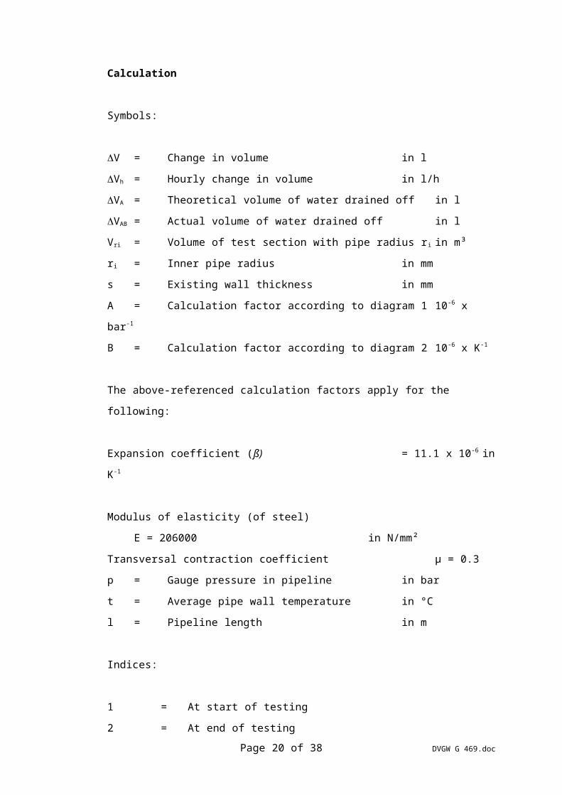
Calculation
Symbols:
V = Change in volume in l
Vh = Hourly change in volume in l/h
VA = Theoretical volume of water drained off in l
VAB = Actual volume of water drained off in l
Vri = Volume of test section with pipe radius ri in m³
ri = Inner pipe radius in mm
s = Existing wall thickness in mm
A = Calculation factor according to diagram 1 10-6 x bar-1
B = Calculation factor according to diagram 2 10-6 x K-1
The above-referenced calculation factors apply for the following:
Expansion coefficient (ß) = 11.1 x 10⁻⁶ in K-1
Modulus of elasticity (of steel)
E = 206000 in N/mm²
Transversal contraction coefficient µ = 0.3
p = Gauge pressure in pipeline in bar
t = Average pipe wall temperature in °C
l = Pipeline length in m
Indices:
1 = At start of testing
2 = At end of testing
x, y, total = Sections or wall thicknesses
0.89 = Constant calculation factor of changes in pressure in 10-6 x bar -1
Page 15 of 27 DVGW G 469.doc

Calculation Formulae
The actual volume of water drained off shall then be compared with the theoretical
volume of water drained off using the following formula:
Vr
sA
Vp pA
i ri ( . ) ( )0891000 1 2 (1)
In the case of different wall thicknesses and pipe radii, the relevant proportional
value of the volumes and wall thicknesses for the quotient r
si shall be determined
as follows:
r
s
r
s
V
V
r
s
V
Vi ix
x
x
total
iy
y
y
total
... (2)
There may be deviations between the theoretical and actual volume of water
drained off. These deviations may be due to negligible volumes of air trapped
inside the pipeline, pipe ovality as well as wall thickness and diameter tolerances.
With regard to sufficient accuracy in evaluation, these deviations should not be
greater than 6 %. The deviations should be taken into consideration with respect to
V
VAB
A
in formula (3).
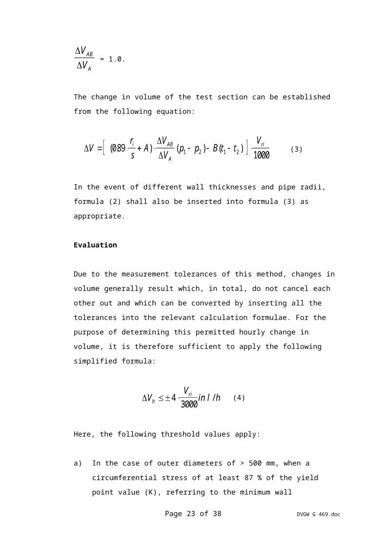
If there is no deviation, the following equation applies:
V
VAB
A
= 1.0.
The change in volume of the test section can be established from the following
equation:
Vr
sA
V
Vp p B t t
Vi AB
A
ri ( . ) ( ) ( )08910001 2 1 2 (3)
Page 16 of 27 DVGW G 469.doc

In the event of different wall thicknesses and pipe radii, formula (2) shall also be
inserted into formula (3) as appropriate.
Evaluation
Due to the measurement tolerances of this method, changes in volume generally
result which, in total, do not cancel each other out and which can be converted by
inserting all the tolerances into the relevant calculation formulae. For the purpose
of determining this permitted hourly change in volume, it is therefore sufficient to
apply the following simplified formula:
VV
in l hhri 4
3000/ (4)
Here, the following threshold values apply:
a) In the case of outer diameters of > 500 mm, when a circumferential stress of
at least 87 % of the yield point value (K), referring to the minimum wall
thickness, has been applied in all piping during pressure testing:
0.3 l/h Vh 4.0 l/h
b) In the case of outer diameters of 500 mm, when a circumferential stress of
at least 87 % of the yield point value (K), referring to the minimum wall
thickness, has not been applied in all piping during pressure testing, and in
the case of outer diameters of < 500 mm:
0.05 l/h Vh 0.8 l/h
c) In the case of piping with single-pass welded circumferential welds:
Vh 0.05 l/h
3.2.2 Pressure Measurement Method Using Water (Pressure Applied Twice) (B 2)
After applying the test pressure as described in method B1 and after a hold time of
approx. 60 minutes, the test pressure shall be reduced as far as possible so that
there is a pressure of min. 2 bar at the absolute highest point along the pipeline.
The test pressure shall then be applied again and generally held for a period of
24 hours. This period can be reduced if the relevant measurement conditions and
Page 17 of 27 DVGW G 469.doc

the pressure profile correspond to the changes in temperature, i.e. if the changes
in volume are constant.
All measurement values shall be recorded during this period. For the purpose of
establishing the pipe wall temperatures along the buried part of the test section, it
is generally sufficient to take thermometer readings at intervals of six hours. All
other measurement values shall be taken at hourly intervals.
After the end of the first hold period, the piping shall be checked for absence of any
air trapped inside.
For this purpose, pressure shall be reduced at least twice. The details described in
Section 3.2.1 (method B 1) shall apply for measurement instrumentation,
evaluation of testing and checking of the pipeline for absence of any air.
3.2.3 Pressure Measurement Method Using Air (B 3)
3.2.3.1General
The test pressure shall be 1.1 times the maximum permitted operating pressure
and must exceed the maximum permitted operating pressure by at least 2 bar.
This method shall be applied on piping which should be entirely buried wherever
possible. Valves and detachable connections should be accessible wherever
possible.
During measurement, the pressure in the pipeline shall be recorded by a pressure
recorder during testing. A pressure recorder (category 1) and a pressure gauge
(category 0.6) with a measurement range of approx. 1.5 times the test pressure are
required for measurement purposes.
Measurement shall commence after application of the test pressure (to be
increased at a rate of max. 3 bar/minute) and after reaching the hold condition. As
a basis for stabilisation of the temperature after injection, a period of one hour may
be assumed for each 1 bar of test pressure, unless this adjustment period can be
reduced by suitable means (e.g. compressor with recooling function).
Page 18 of 27 DVGW G 469.doc

The impact of the instrument line on the results involved must be minimised.
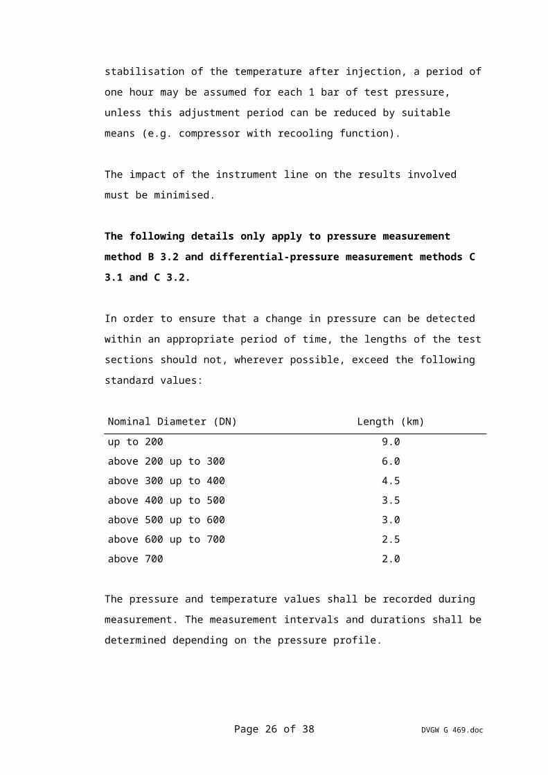
The following details only apply to pressure measurement method B 3.2 and
differential-pressure measurement methods C 3.1 and C 3.2.
In order to ensure that a change in pressure can be detected within an appropriate
period of time, the lengths of the test sections should not, wherever possible,
exceed the following standard values:
Nominal Diameter (DN) Length (km)
up to 200 9.0
above 200 up to 300 6.0
above 300 up to 400 4.5
above 400 up to 500 3.5
above 500 up to 600 3.0
above 600 up to 700 2.5
above 700 2.0
The pressure and temperature values shall be recorded during measurement. The
measurement intervals and durations shall be determined depending on the
pressure profile.
If part of the test section cannot be fully buried for imperative reasons, the
temperatures shall be measured separately and included in the calculation.
In order to establish the air temperature inside the pipeline, the soil temperatures
along the pipeline shall be measured at two locations at least, taking into
consideration local conditions.
The soil temperatures along the pipeline and on the test cylinder shall be measured
by thermometers with scale divisions of 0.05 °C, whereas the air temperature and
pipe wall temperature on exposed pipeline sections shall be measured by
thermometers with scale divisions of 0.1 °C. The soil thermometers should have a
scale length of min. 12 mm/0 °C. The use of other temperature metering devices,
e.g. resistance thermometers, assumes adherence to the above-referenced
accuracy of measurement.
Page 19 of 27 DVGW G 469.doc
The change in pressure (p) established after taking into consideration the impact of
temperature may not exceed the following absolute value:
pDN
h in mbarperm 400
(5)
where
pperm = Permitted change in pressure
DN = Nominal diameter
h = Measurement duration (in hours)
It is recommended to perform check calculations during the measurement period in
order to obtain early indications of any leaks along the pipeline.
The pipeline shall be considered leak-proof, i.e. tight, if, at the end of the testing
period applied for evaluation purposes, p < p perm.
The following details only apply to pressure measurement method B 3.2 and
differential-pressure measurement method C 3.2.
A test certificate from the calibration authority or the German National Metrological
Institute (PTB) must be available for pressurisers (e.g. piston pressure gauges).
Temperature must be compensated with an accuracy of 0.1 °C.
The pressuriser must clearly indicate a change in pressure of min. 1 mbar.
A barometer with a measurement accuracy of 1 mbar shall be used for metering
the atmospheric pressure.
3.2.3.2Simplified Pressure Measurement Method (B 3.1)
In the case of buried piping, the hold time shall be governed by the relevant
regulations specified in the DVGW code of practice; the hold time for exposed
piping shall be at least two hours. During the hold time and in observance of the
temperature conditions, a drop in pressure at the pressure recorder is permitted in
line with the relevant regulations specified in the DVGW code of practice.
Page 20 of 27 DVGW G 469.doc

3.2.3.3Pressure Measurement Method Using Precision Pressure Gauges (e.g. Piston
Pressure Gauges) (B 3.2)
The piping shall be checked for leaks by assessing the pressure along the piping
during the testing period.
The link between the pressure oil in the pressure gauge and the air shall be visibly
indicated in a suitable manner (e.g. by a liquid level indicator).
Evaluation:
The actual drop in pressure may be calculated using the following formula:
p p p p p
p p
Tt t in baramb amb
amb
LL L
( ' ) ( ' )
' )( )1 1 2 2
1 1
11 2
(6)
Symbols:
p = Change in pressure
t = Temperature on the piping or test cylinder, average value of all
simultaneously measured temperatures (°C), taking into consideration
the relevant piping sections
p = Absolute pressure (in mbar)
pamb = Atmospheric pressure (in mbar)
p' = Test pressure (in mbar)
T = Absolute temperature (in °K)
T' = 273.15 + t °K
Index 1 = Beginning
Index 2 = End of test period applied for evaluation purposes
Index 3 = on the piping
Page 21 of 27 DVGW G 469.doc

3.3 Differential-Pressure Measurement Method Using Air (C 3)
3.3.1 General
The piping shall be checked for leaks taking into consideration the changes in
temperature between the piping pressure and the pressure of a comparative device
(e.g. test cylinder or piston pressure gauge). Otherwise, the details specified in
Section 3.2.3.1 apply.
3.3.2 Differential-Pressure Measurement Method Using Test Cylinders (C 3.1)
Measurements should be evaluated within a temperature range in which the
temperature of the outside air has the same tendency at both the beginning and
the end; i.e. the starting and end points of evaluation should be on an either rising
or falling temperature curve.
If the temperatures of the outside air at the beginning and end of pressure testing
are not identical, the impact of this difference in temperature on the exposed piping
sections shall be taken into consideration in the calculation.
Equipment which clearly indicates a change in pressure of min. 1 mbar shall be
used for the purpose of measuring differential pressure.
The change in pressure may be calculated in line with the isochoric state equation
using the following formula:
p U U pt t
Tp
t t
Tin mbar
L L
L
F F
F
1 2
1 2
1
1 2
1
( ) ( )(7)
Symbols (see also the explanation of symbols under formula (6)):
U = Difference between piping pressure and cylinder pressure, measured
at the differential-pressure meter (in mbar)
p = (p' + pamb) (in mbar)
Index F = at the test cylinder
Page 22 of 27 DVGW G 469.doc
3.3.3 Differential-Pressure Measurement using Pressurisers (C 3.2)
Equipment capable of being subjected to unilateral pressure, e.g. Barton cell or
electrical transducer, shall be used for the purpose of measuring the differential
pressure.
The counterpressure at the pressuriser shall be set to the piping pressure before
measurement and shall not be modified during the measurement period. The
dependence of temperature on pressure may have to be taken into consideration.
The drop in pressure may be calculated using the following formula:
p U p U pp p
Tt t in mbaramb amb
amb
LL L
( ' ) ( ' )
( ' )( )1 1 2 2
1 1
11 2 (8)
Symbols: see the explanation of symbols under formulae (6) and (7).
3.4 Pressure/Volume Measurement Methods (D)
Pressure/Volume Measurement Method (Pressure Applied Twice) (D 2)
Pressure/volume measurement methods are hydrostatic tests subjecting piping and
pipe bends up to the yield strength of piping, taking into consideration the
maximum permitted integral plastic deformation of the pipeline.
This method shall be applied in line with VdTÜV Code of Practice (Pipelines) 1060.
4 Specifications, Regulations and Technical Rules
4.1 Accident Prevention Regulations (UVV)
VBG 1 General regulations
VBG 50 Work on gas pipelines
Source of supply: Carl Heymanns Verlag KG
Luxemburger Straße 449
50939 Köln
Page 23 of 27 DVGW G 469.doc

4.2 DVGW Codes of Practice
G 260/I Gas composition
G 458 Subsequent boosting of gas pipeline pressure
G 459 House service connections for an operational pressure of up to
4 bar - Installation
G 461/I Installation of gas pipelines with an operational pressure of up
to 4 bar, comprising ductile cast-iron pressure piping and
fittings
G 461/II Installation of gas pipelines with an operational pressure of
more than 4 bar up to 16 bar, comprising ductile cast-iron
pressure piping and fittings
G 462/I Installation of steel gas pipelines with an operational pressure
of up to 4 bar
G 462/II Steel gas pipelines with an operational pressure of more than 4
bar up to 16 bar - Installation
G 463 Installation of steel gas pipelines with an operational pressure
of more than 16 bar
G 465/II Work on gas piping networks with an operational pressure of
up to 4 bar
G 466/I Steel gas piping networks with an operational pressure of more
than 4 bar - Maintenance
G 466/II Ductile cast-iron gas piping networks with an operational
pressure of more than 4 bar up to 16 bar - Maintenance
Page 24 of 27 DVGW G 469.doc

G 472 Laying of hard-PVC piping with an operational pressure of up
to 1 bar and hard-PE piping with an operational pressure of up
to 4 bar for gas pipelines
G 490 Technical regulations for the construction and equipment of
gas pressure regulators with inlet pressures of more than 100
mbar up to 4 bar inclusive
G 491 Technical regulations for the construction and equipment of
gas
(in revision) pressure regulators with inlet pressures of more than 4 bar up
to 100 bar inclusive
G 492/II Construction and equipment of facilities for metering gas
(in revision) volumes with a throughflow of min. 3000 m³/h at normal
conditions and a pressure of more than 4 bar - Bulk gas
metering
G 496 Piping in gas installations
G 497 Compressor stations on gas transmission pipelines
G 498 Continuous-flow pressure tanks in gas pipelines and facilities in
public gas distribution networks - Manufacture, installation,
commissioning and operation
G 600 Technical regulations for gas facilities
(DVGW - TRGI '86)
Source of supply: ZfGW-Verlag GmbH
Postfach 90 10 80
Voltastraße 79
60486 Frankfurt/Main
Page 25 of 27 DVGW G 469.doc
4.3 DIN Standards
DIN 1304, Part 1 Symbols; general symbols
E 01.84
DIN 2401, Part 1 Pressure-containing piping components; details on
05.77 pressures and temperatures, definitions, nominal pressure
ratings
DIN 2402 Nominal sizes; terms; identification numbers
02.76
DIN 2470, Part 1 Steel gas pipelines for permissible service pressures
02.77 up to 16 bar; requirements on pipeline components
(in revision)
DIN 2470, Part 2 Steel gas pipelines for admissible service pressures
05.83 exceeding 16 bar, requirements of pipeline components
DIN 3230, Part 5 Technical conditions of delivery of valves; valves for gas
08.84 installations and gas pipelines; requirements and tests
DIN 30 690, Part 1 Component parts in the gas transmission and distribution;
07.83 requirements for component parts in the gas stations
DIN 50 104 Internal pressure test for hollow bodies of various shapes
11.83 up to a specified internal pressure (water pressure test)
Source of supply: Beuth Verlag GmbH
Burggrafenstr. 4 - 7
10787 Berlin
or
ZfGW-Verlag GmbH
Voltastraße 79
60486 Frankfurt/Main
Page 26 of 27 DVGW G 469.doc

4.4 VdTÜV Codes of Practice
VdTÜV (Pipelines) 1060
08.77 Directives for performance of stress tests
Source of supply: Verlag TÜV Rheinland
Am Grauen Stein
51105 Köln
Page 27 of 27 DVGW G 469.doc