dutton associates - nasa langley gis team home page · controls- naw-824: general electric co. 4....
TRANSCRIPT

REPORT >
Historic Structures Report 20-Foot Spin Tunnel (Building 645) NASA Langley Research Center DATE> JULY, 2013 LOCATION > Hampton, Virginia PREPARED FOR >
Straughan Environmental, Inc
PREPARED BY > Dutton + Associates, LLC
Dutton + Associates CULTURAL RESOURCE SURVEY, PLANNING, AND MANAGEMENT
NASA LANGLEY RESEARCH CENTER, VDHR # 114-5313-0406 20-FOOT SPIN TUNNEL (Building 645) 645 Andrews Street NASA Langley Research Center Hampton Virginia
PHOTOGRAPHS WRITTEN HISTORICAL AND DESCRIPTIVE DATA
Historic Structure Report Virginia Department of Historic Resources
Richmond, Virginia

HISTORIC STRUCTURES REPORT
NASA LANGLEY RESEARCH CENTER 20-FOOT SPIN TUNNEL
(Building 645)
VDHR ID# 114-5313-0406 Location: The 20-Foot Spin Tunnel (NASA Building 645) is located in the NASA
Langley Research Center (LaRC) East Area at 645 Andrews Street. NASA LaRC is located within the City of Hampton, Virginia.
The 20-Foot Spin Tunnel is located at latitude: 37.083492, longitude:
-76.340571. This coordinate represents the approximate center of the facility. This coordinate was obtained on June 3, 2013, using Google Earth. The datum used for this point is North American Datum 1983. The tunnel’s location is restricted to the public.
Date of Construction: 1941 Present Owner: United States National Aeronautics and Space Administration (NASA) Present Use: Research and Development Significance: The NASA LaRC 20-Foot Spin Tunnel (Building 645) is a significant
historic resource at the national level for its association with advances in aerodynamics research and testing conducted by the National Advisory Committee for Aeronautics (NACA) and NASA LaRC. The 20-Foot Spin Tunnel was constructed in 1941 to assist researchers studying the dreaded tailspin. It replaced the earlier 15-Foot Spin Tunnel and allowed additional research into spin recovery behavior, tumbling resistance, and recovery from other out-of-control situations.
The 20-Foot Spin Tunnel continues to be used and is the operational spin tunnel in the Western Hemisphere. It is also the largest and most productive of such tunnels in the world. As a result of its unique capabilities, the Spin Tunnel supports the development of all United States military fighter and attack airplanes, primary trainers, and bombers. It is also the only available resource for the general aviation aircraft manufacturers to conduct proprietary research on their products. SpinTunnel data is vital because it develops life-saving aircraft spin recovery methods. As such, is on the list of Critical National Facilities. Nearly every U.S. fighter, light bomber, attack plane and trainer has been tested in Langley’s 20-Foot Spin Tunnel.

NASA LANGLEY RESEARCH CENTER, 20-FOOT SPIN TUNNEL
VDHR ID# 114-5313-0406 (Page 2)
In addition to supporting airplane development, the VST has provided key subsonic, dynamic-stability data for many non-crewed and human-rated atmospheric entry vehicles. Examples include Pioneer Venus, Stardust, and Mars Sample Return prototypes; and the Mercury, Gemini and Apollo space capsules. Most recently, the VST is contributing to development of NASA's Orion crew exploration vehicle with free-fall, dynamic-stability assessments of the Orion launch-abort vehicle, as well as rotary-balance studies of the ARES Mars Airplane configuration.
Historian(s): Robert J. Taylor, Jr., Dutton + Associates, LLC, Richmond, Virginia.
Report completed June 2013. Project Information: This Historic Structures Report was prepared by Dutton + Associates,
LLC for NASA Langley Research Center under contract with Straughan Environmental, Inc in compliance with the National Historic Preservation Act (NHPA) of 1966 as amended, and to satisfy the standard documentation requirements of the Programmatic Agreement (PA) among NASA, the Virginia State Historic Preservation Office and the Advisory Council on Historic Preservation for Management of Facilities, Infrastructure and Sites at NASA LaRC (dated January 15, 2010). Stipulation V.G of the PA provides for implementing Standard Documentation Measures when LaRC plans to demolish an historic building or structure. Architectural fieldwork, preparation of descriptions and historical context, and photography were completed by D+A Architectural Historian, Robert J. Taylor, Jr. Historical information and assistance was provided by NASA LaRC and Straughan. This package was prepared under consultation with the Virginia Department of Historical Resources (VDHR).

NASA LANGLEY RESEARCH CENTER, 20-FOOT SPIN TUNNEL
VDHR ID# 114-5313-0406 (Page 3)
PART I. HISTORICAL INFORMATION
A. Physical History:
1. Date of Construction: 1940-41
2. Designers: Charles H. Zimmerman
3. Contractors: NAW-785: W. P. Thurston Co. Richmond, Va. Motor and Controls- NAW-824: General Electric Co. 4. Original Plans: The current plan and configuration of the 20-Foot Spin Tunnel nearly matches the original plan for the facility as constructed. Beginning in the fall of 1940, the foundation for the building was poured and the structure was assembled over the following year. The tunnel consisted of 12-sided polygon structure measuring 63-feet across the widest part of the base and 75-feet, or roughly 5-stories tall. When constructed, the primary access was by an elevated and enclosed walkway from the third floor of the nearby 15-Foot Free-Spinning Tunnel (Building 646) that led to the integral control and observation room located at would approximately be the 4th floor of the 20-Foot Spin Tunnel Structure. This room was at the same level as the test section in the middle of the structure where models would be flown. 5. Alterations and Additions: Building 645 has undergone relatively few alterations and continues in operation much as it did when constructed. The most significant addition to the facility was the construction of an associated office and laboratory building in the late 1970s (Building 645A). That 5-story brick building was constructed just to the north of the wind tunnel and provided additional access to the facility by an elevated walkway. In 1979, the control and observation room were also outfitted with new computers and systems. In 1993, the facility underwent a major $1.9 million improvement and overhaul. This renovation included the replacement or refurbishment of all the tunnel’s primary components. The original 1941 motor was refurbished with new technology boosting its power output from 400 to 700 horsepower. The original wooden 3-blade fixed-pitch fan was replaced with a 5-blade variable-pitch composite fan and all associated material. This modification allowed a change in the speed of airflow in the tunnel to be conducted more easily and reliably. The rotary balance system was also replaced with a newer model, and lastly the original manual video-tracking system was replaced with an automated system. Other small changes included the replacement and relocation of the model catching net closer to the bottom of the tunnel and moving the honeycomb up
NASA LANGLEY RESEARCH CENTER, 20-FOOT SPIN TUNNEL
VDHR ID# 114-5313-0406 (Page 4)
from bottom of the tunnel, both to allow more consistent airflow. Lastly, padding was added to the interior walls of the test section to protect models from damage.
B. Historical Context: The National Advisory Committee for Aeronautics (NACA) was established on March 3, 1915, with the mission of supervising and directing the scientific study of the problems of flight, with a view to their practical solution. European aviation advances and the potential for U.S. involvement in the First World War had largely been responsible for the creation of the NACA, which was officially approved as a rider on the naval appropriations bill for 1916. The NACA was appropriated $53,580 for lab construction on August 29, 1916, but no funds were provided for purchasing or developing a laboratory site. Committee members were well aware of the Army's $300,000 appropriation for a flying field, and apparently saw it as their best opportunity for a laboratory location.1 The NACA initiated specific actions to establish a joint civil-military experimental field with the Army, and efforts to advance civil and military aviation coincided at a site eventually known as Langley Field, lying four miles north of Hampton, Virginia, on the flat lands facing the two branches of Back River, which opens out into the Chesapeake Bay.2 Work began slowly at Langley to plat streets, construct buildings, and grade two aircraft runways; however the U.S. entry into World War I in 1917 brought about accelerated construction and increases in money as well as personnel. NACA requested a small plot be assigned to them for the construction of their experimental laboratory at Langley, "near the water front and preferably near the western end of the field".3 The space was provided to them unofficially, but the army did not want to make an official sanction until further into the planning and development process of Langley Field. When the war ended in 1918, Army airfield construction immediately came to a halt. Many bases across the country had been leased and were simply abandoned; however Langley had been created before the war with the intention of providing an experimental flying field and proving ground for aircraft, and therefore was retained after the war to carry out its original intent.4 The NACA once again repeated their request to officially have their plot at Langley sanctioned to them, stating that the laboratory building had already been completed and that construction of a wind tunnel for research was underway. It was therefore necessary to officially recognize their claim so as to avoid potential disputes with the Army.
1 Brown, Jerold E., Where Eagles Land: Planning and Development of U.S. Army Airfields, 1910-1941. Washington,
D.C.: Office of Air Force History, 1985: 60. 2 NASA History Program Office. Langley Research Center. 3 Hansen, James R. Engineer in Charge. The NASA History Series Scientific and Technical Information Office
National Aeronautics and Space Administration Washington, D.C., 1987: 11 4 Maurer Maurer, Aviation in the U.S. Army, 1919-1939. Washington, D.C.: Office of Air Force History, 1987: 109.

NASA LANGLEY RESEARCH CENTER, 20-FOOT SPIN TUNNEL
VDHR ID# 114-5313-0406 (Page 5)
By this time however, the Army Air Service had been reorganized and the NACA issue became entangled in the larger question of how post-war Army aviation would be structured. The Army believed there was no need at all for a separate organization to conduct experiments in aviation and aeronautics and claimed that such a division of control at Langley would become burdensome. The issue was resolved however when acting Secretary of War Benedict Crowell approved a memorandum stating that the “portion of Langley Field known as Plot No. 16 be definitely set aside for use by the National-Advisory Committee for Aeronautics for their purposes in constructing laboratories or other utilities necessary in scientific research and experiments in the problems of flight." The issue of dual control was resolved by authorizing NACA to conduct its work independent of the Air Service, with the exception that NACA personnel would come under the control of the Post Commander in matters pertaining to discipline, fire, guard, police and sanitation. Despite the Army’s continued reservations, the NACA's laboratory was officially dedicated in conjunction with completion of its first wind tunnel on June 11, 1920. NACA's laboratory was officially named the Langley Memorial Aeronautical Laboratory (LMAL) in honor of Samuel Pierpont Langley, the "father of aviation." On January 15, 1921, legislation authorizing occupancy of quarters by LMAL personnel passed the Senate and was favorably reported to the House. Later that year, a new and more sympathetic Commanding Officer arrived at Langley Field, which greatly improved military-civilian relations. From this point on, the NACA’s researchers were finally able to conduct their work in earnest.5 When LMAL was officially dedicated in June 1920, the laboratory complex included three buildings. The “Research Laboratory” (Building 587), completed in 1918, which included administrative offices, drafting, machine/woodworking shops, and photography and instrument labs, as well as a lunchroom on the second floor. The wind tunnel building (Building 580), completed in 1920, which housed Tunnel No. 1, and the third building, which was a temporary structure for the engine dynamometer lab equipment. LMAL was in full operation by April 1921 and the NACA hired Dr. Max Munk to direct its growing aeronautical research program. A German theoretical aerodynamicist from the Zeppelin Company, Munk had abilities as a theoretician and generalist which the Committee expected would enable him to draw conclusions from LMAL’s research.6 Munk soon set about designing the LMAL’s second wind tunnel to address the problem
5 Victory, John, “The Langley Laboratory,” TMs (Rough Draft) [photocopy] citing Memorandum Griffith to
Victory, January 5, 1922 Langley Historical Archive, NASA Langley Research Center, Hampton, Virginia. 6 Roland, Alex, Model Research: The National Advisory Committee for Aeronautics, 1915-1958. Washington, D.C.:
National Aeronautics and Space Administration, 1985: 92.

NASA LANGLEY RESEARCH CENTER, 20-FOOT SPIN TUNNEL
VDHR ID# 114-5313-0406 (Page 6)
of “scale effect.” This phenomenon had posed a serious problem for wind tunnel research, as it skewed research results and required correction to accurately simulate conditions encountered by an actual airplane in flight. In response, Munk designed and built the Variable Density Tunnel (VDT), which could vary air density “so that almost any model of reasonable size could be tested under conditions comparable to those encountered by a full-scale aircraft in flight”.7 Another problem that faced researchers as the evolution of flight continued was the dreaded tailspin. The international aeronautical engineering community knew very little about the primary factors that influenced the spin or the relative effectiveness of piloting methods to recover from spins. In the 1920s Langley’s staff conceived a testing technique that used catapult and/or hand-launched aircraft models dropped from the interior ceiling of an Army airship hangar at Langley which was about 105 feet high. After using the method to study spins, the Langley staff concluded that the catapult technique was excessively time consuming and resulted in frequent damage to the fragile models. Langley then constructed a 5-ft diameter vertical wind tunnel in Building 580 (previously the site of the first NACA wind tunnel) to provide for measurements of the aerodynamic loads on aircraft models during simulated spinning motions. The models were not in free-flight during the tests, but were mounted to a balance that was driven in simulated spinning motions by an electric motor. Airflow in this early tunnel was vertically downward, and tests were directed at the aerodynamics encountered in the spin. Using the aerodynamic data in equations of motion, the staff attempted to predict spin behavior. Meanwhile, the British researchers at the Royal Aeronautical Establishment (RAE) in England had observed the disappointing NACA efforts with catapult-launched models and subsequently conceived the idea of a vertical wind tunnel to permit free-spinning tests of aircraft models. Such a technique was much more productive than either catapult launches or wind-tunnel aerodynamic measurements. Following initial trials with a small model of the free-spinning tunnel, the RAE constructed a 15-ft full-scale version of the tunnel and proceeded to conduct fundamental research on spinning and spin recovery. Learning of the success of free-spinning tunnel in England, researchers and management at NACA-Langley proceeded to design and construct a similar 15-ft free-spinning tunnel in 1934 under the direction of Charles H. Zimmerman, the Chief of the Stability and Control Section. The construction site for the new tunnel was in its own facility (present-day Building 646) located next to the Langley Full Scale Tunnel. Research operations in the NACA 15-Foot Free-Spinning Tunnel began in 1935. The airflow in the 15-ft tunnel was vertically upward to simulate the downward descent velocity of an aircraft during spins. At the beginning of a typical test, the model was mounted with pro-spin controls
7 Ibid

NASA LANGLEY RESEARCH CENTER, 20-FOOT SPIN TUNNEL
VDHR ID# 114-5313-0406 (Page 7)
on a launching spindle at the end of a long wooden rod held by a tunnel technician. A tunnel operator increased the vertical air speed until the air forces on the model equaled its weight. At this point, the model automatically disengaged from the spindle and continued to rotate in a spin as the airspeed was continuously adjusted to maintain the model’s position at eye level in the test section. The model’s control surfaces were moved from pro-spin settings to pre-determined anti-spin settings by a clockwork mechanism, and the rapidity of recovery from the spin was noted. After the test was completed, the tunnel airspeed was decreased and the model was allowed to settle into a large net at the bottom of the test section. The model was then recovered with a long- handled clamp and prepared for the next test. Testing in the 15-Foot Free-Spinning tunnel was successful and led to a number of advances in tailspin science. However, as aircraft designs evolved in the late 1930s, the increasing weight of full-scale aircraft required heavier models which in turn required higher tunnel air speed capability. The free-spinning tunnel had been designed with a maximum speed of only about 40 mph. Although the 15-ft tunnel remained operational until the mid-1940s, it was replaced by the more capable 20-Foot Spin Tunnel in its own facility (Building 645) in 1941. During World War II, the two tunnels combined to test over 300 different military aircraft designs, resulting in modifications to over half the configurations to improve their spin recovery characteristics. Following World War II, the smaller and less capable 15-ft Spin Tunnel was deactivated, and the tunnel was demolished and removed from Building 646.
Meanwhile, the 20-Foot Spin Tunnel continued to be active and has remained in service to the present-day. Today, this versatile testing facility is used to determine the size and effectiveness of emergency spin-recovery parachute systems for flight-test aircraft by deploying various parachute configurations from the spinning model. In addition, unconventional maneuvers such as uncontrollable nose-over-tail gyrations known as “tumbling” can be investigated. In its recent history the tunnel has also been used to evaluate the stability of vertically descending configurations including munitions and parachute/capsule systems. The spin tunnel has supported the development of nearly all U. S. military fighter and attack aircraft, trainers and bombers during its 68-year history, with over 600 projects to date.

NASA LANGLEY RESEARCH CENTER, 20-FOOT SPIN TUNNEL
VDHR ID# 114-5313-0406 (Page 8)
Chronology 1940 Construction Initiated 1941 20-Foot Spin Tunnel Becomes Operational 1978 Associated Office and Laboratory Building Constructed 1979 Control and Observation Room Upgraded with New Systems 1993 Major Upgrade and Renovation of Tunnel’s Primary Components 2013 Still Operational, but Slated for Potential Future Demolition
NASA LANGLEY RESEARCH CENTER, 20-FOOT SPIN TUNNEL
VDHR ID# 114-5313-0406 (Page 9)
PART II. STRUCTURAL/DESIGN INFORMATION
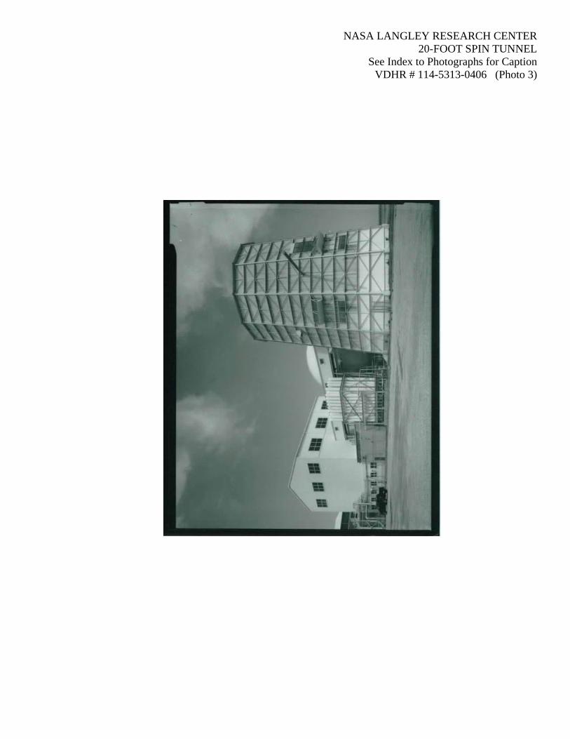
A. General Description: Site The 20-Foot Spin Tunnel (Building 645) is located on the south side of Andrews Street near its eastern terminus at 645 Andrews Street. It is part of compound of buildings and facilities that include it, its associated office and laboratory building (Building 645A), as well as Building 644 (the 12-Foot Low-Speed Tunnel and formerly the 12-Foot Free-Flight Tunnel) and Building 646 (the former 15-Foot Free-Spinning Tunnel and currently the East Area Compressor Building). The 20-Foot Spin Tunnel is located at the east end of this compound. This compound is set back from Andrews Street with a row of parking along the north side of the buildings. This is roughly the eastern terminus of Andrews Street, and the road is essentially a parking lot at this point, rather than a formal delineated street, which ends at Hunting Avenue, just to the west. To the east of the compound of facilities is a gravel extension of Andrews Street that doglegs around the side of the 20-Foot Spin Tunnel. Beyond Andrews Street to the east is a narrow grassy area and the Back River. To the west side of the compound is Hunting Avenue, which divides it from Building 647, the East Shop Building and former wind tunnel facility, on the adjacent block. To the rear of the compound is a large open gravel covered area that until 2010 was the site of the Full-Scale Tunnel (now demolished). The 20-Foot Spin Tunnel sits immediately adjacent to Andrews Street on the east. Just to the north is the associated office and laboratory building and just to the south is the large open gravel area formerly occupied by the Full Scale Tunnel. Immediately to the west of the building is chainlink fence enclosed area that contains the spherical 12-Foot Low-Speed Tunnel and a variety of vacuum tubes, pipework, and other equipment that it and the 12-Foot Low-Speed Tunnel share. Structure Exterior The 20-Foot Spin Tunnel is a five-story, 12-sided structure which measures 63-feet wide at the base and occupies roughly 3,160 square-feet of ground area. The structure is 75-feet tall, or approximately five-stories, although the interior is mostly open with only one-formal floor at approximately the 4th floor height which contains the control and observation room. It has a steel frame exoskeleton structural system enclosing corrugated metal sheathing. Steel I-beams are located at the breaks of the corners, secondary steel angles span horizontally between the I-beams dividing each vertical plane into thirteen sections. Every other side of the structure has vent panels in the 4th and 6th section up. The west-north-west and west-south-west sides also contain large industrial-style fixed

NASA LANGLEY RESEARCH CENTER, 20-FOOT SPIN TUNNEL
VDHR ID# 114-5313-0406 (Page 10)
windows spanning the 7th and 8th sections up. Diagonal steel channels reinforce the structure unifying three of the horizontal steel angles. The diagonals are welded to steel plates at the junctures with the horizontal steel angles. The structure is set on a poured-concrete base and is topped by a shallow-pitched conical roof covered with sheet metal. The building does not have a true “front” although there is a ground-level entrance on the northeast side. This entrance consists of a single leaf steel door with a single light that is approached by a concrete stoop with four steps and a pipe rail. The stoop is protected by a metal canopy supported by four square metal posts. At roughly the third floor level of the north side, a short enclosed spanning walkway connects the structure to its associated office and laboratory building. At roughly the fourth floor level on the west side, a longer enclosed walkway connects the structure to Building 646. It is supported by a series of truss-type legs set on concrete footings within the chainlink fence enclosed area between these two buildings. The walkway is clad with raised-seam metal sheathing and topped with flat metal roof. Four small fixed pane windows pierce the walls on each side of the walkway. Structure Interior The interior of the 20-Foot Spin Tunnel is mostly integral to the operation of the wind tunnel and therefore its appearance is reflective of this. Inside the ground-level entrance is the outer shaft or down-draft portion of the tunnel. This narrow area has exposed concrete floors and stretches up the full-height of the structure. Narrow steel fins and braces span the area periodically. In the center of the structure is the 12-sided throat and updraft area. Wind screens form this area at ground level; however it is enclosed with sheet metal the rest of the way up. The control and observation room at roughly the 4th floor is accessible by the exterior walkways from the office and laboratory building as well as Building 646. Both of these walkways lead into the tunnel structure where short metal catwalks bridge the down-draft area. These catwalks lead into the control and observation room which encircles the test area in the center of the structure. This room contains all the equipment and computers for the operation of the wind tunnel. It has been renovated and finished with carpeted floors, drywall walls, and acoustic tile drop ceilings. Several of the interior walls of this room hold large steel frame window units that open to allow access into the testing chamber.
1. Character: The 20-Foot Spin Tunnel has a unique character that is reflective of its wind tunnel design. The 12-sided exterior of the building is one-of-a-kind at NASA LaRC and stands out amongst other wind tunnel structures. Very little change has occurred to the exterior of the building other than replacement windows, so it retains its 1940s character with narrow-ribbed corrugated metal and a patina finish. The interior of the structure is also unique in that the ground level entrance takes you directly into the wind tunnel circuit. Its structure and

NASA LANGLEY RESEARCH CENTER, 20-FOOT SPIN TUNNEL
VDHR ID# 114-5313-0406 (Page 11)
framing are all completely exposed and the turn vanes and fans can all be seen. The control and observation room has a unique configuration with a highly visible test chamber created by the large hinging metal windows. 2. Condition of Fabric: Overall, the 20-Foot Spin Tunnel remains in a good condition, and continues to be used in testing applications. The structure has been consistently maintained and repairs made where needed. The exterior has been painted and exhibits only minor rust and surface impairments. Some sections of corrugated metal near the bottom of the structure have been replaced. New Windows have also been added on the exterior to allow more natural light into the interior. The control and observation room has been renovated with new finishes and all new equipment.
B. Construction: The construction methods used at the 20-Foot Spin Tunnel are reflective of the specialized research carried out at the facility. Although the design of the structure is innovative and complex, the construction is relatively simple. The structure is formed by a steel frame with corrugated metal sheathing, although the frame is placed on the exterior so that the interior surface is smooth. Overall, the structure consists of an open central core surrounded by an open concentric ring. The two spaces are connected at ground level by wind screens and at the top with the fan and turning vanes. The framing is reinforced and the sheathing is rigid enough to contain the high wind speeds and air pressure created during tests.

NASA LANGLEY RESEARCH CENTER, 20-FOOT SPIN TUNNEL
VDHR ID# 114-5313-0406 (Page 12)
C. Mechanicals/Operation: Summary The 20-Foot Spin Tunnel is used to conduct research in free-spin and tumbling using dynamic models. During tests, air is driven by a motor-driven fan upwards through the centrally located test section. Air is returned through turn-vanes at the ceiling that drive it back down the return passage between the test section and the exterior of the structure. It is then guided through a screen mesh at the base of the structure where the large fan drives it back up the test section again. Scaled models are then introduced into the test section manually where they are suspended by the airflow. The models can be introduced in a spinning motion for research in various free-spin and tumbling scenarios or stationary for decent-related studies. The test section is bordered by the control and observation room in which the operators may monitor the test in process through large windows and analyze it with various computer and video tracking systems. Design The tunnel is designed with a closed throat and annular return passage. The test section is vertical with 12 sides, 20-feet across the flats and 25-feet high. Air speed is variable from 0 to 90 feet per second with accelerations up 15 ft/sec² and decelerations up to 25 ft/sec². Stagnation pressure is atmospheric and the turbulence factor is 2. The Reynolds number per foot is 0 to 0.62 x 10^6. The test medium is air. Originally powered by a 400 hp maindrive with short-term 1300 hp capability, it is now powered by a 700 hp motor. Operation The 20-Foot Spin Tunnel is used to conduct dynamic model free-spin and tumbling research, anti-spin parachute research, and aerodynamic measurements using a rotary balance technique. Free-spin research defines the spin and spin recovery characteristics of a given configuration and tumble research determines its susceptibility to out-of-control pitch autorotation. The rotary balance technique provides force, moment, and pressure measurements under rotating conditions and thus allows detailed analysis of the spin aerodynamics of a given configuration. As a result of its unique capabilities, the Spin Tunnel supports the development of all United States military fighter and attack airplanes, primary trainers, and bombers. It is also the only available resource for the general aviation aircraft manufacturers to conduct proprietary research on their products.

NASA LANGLEY RESEARCH CENTER, 20-FOOT SPIN TUNNEL
VDHR ID# 114-5313-0406 (Page 13)
During testing, models are launched with spinning rotation into the airstream by hand. Spin recovery characteristics are studied by remotely actuating the aerodynamic controls of models to predetermined positions. Force and moment testing is performed using a gooseneck rotary arm model support which permits angles of attack and sideslip from 0° to 360°. Video and motion picture records are used to record the tumbling, spinning, and recovery characteristics in the spin tunnel tests. Photographs are taken of the spinning motion by a side camera or by synchronized cameras on the side and at the bottom of the tunnel. As the side camera photographs the motion, it also photographs readings of a timing device and of a pitot-static tube; thus, records of time and velocity are registered on film. A six-component rotary balance is available in the tunnel to obtain force and moment data at spinning attitudes and to provide aerodynamic data for analytical studies. For recovery, the tunnel operator sets up a magnetic field in the tunnel where the model is spinning by allowing a current to pass through copper coils placed around the periphery of the tunnel. A magnet in the model moves to align with the magnetic field and, in so doing, trips a catch which allows controls to move, a parachute to open, a rocket to fire, or an item to be jettisoned. The model is allowed to lower into the catch-net at the bottom of the test section where it may be retrieved for further studies.
Tunnel Specifications
Speed: Mach 0.08
Reynolds Number: 0.55 x10⁶ per foot Pressure: Atmospheric
Temperature: Ambient Test Section Size: 20 feet across
Test Section Length: 25 feet high
Drive Power: 700 horsepower continuous 1,300 short burst

NASA LANGLEY RESEARCH CENTER, 20-FOOT SPIN TUNNEL
VDHR ID# 114-5313-0406 (Page 14)
PART III. SOURCES OF INFORMATION A. Primary Sources
Campbell, John. “Free and Semi-Free Model Flight-Testing Techniques Used in Low-Speed
Studies of Dynamic Stability and Control”. AGARDograph Journal Of The North Atlantic Treaty Organization Advisory Group For Aeronautical Research And Development. October 1963.
NACA Tunnel Details and Costs Record. Free-Spinning Wind Tunnel, Free-Flight Tunnel, and
Connecting Buildings. June 30, 1942. NASA LaRC Archives. Available online at: http://crgis.ndc.nasa.gov/crgis/images/d/d9/1942-06-30_Low_Speed_Tunnel_Cost_and_Details.pdf
NASA. Cultural Resources, History, Archaeology, and GIS Website. Langley Research Center.
Available online at: http://crgis.ndc.nasa.gov/historic/645 NASA. “Langley Research Center.” NASA History Program Office. Available online at:
http://history.nasa.gov/centerhistories/langley.htm NASA LaRC. “Facility Detail for the 20-Foot Vertical Spin Tunnel and Offices.” March 20,
1996. NASA LaRC Archives. Victory, John, “The Langley Laboratory,” TMs (Rough Draft) [photocopy] citing Memorandum
Griffith to Victory, January 5, 1922 Langley Historical Archive, NASA Langley Research Center, Hampton, Virginia.
Shortal, Joseph A and Clayton J. Osterhout. Preliminary Stability and Control Tests in the NACA
Free-Flight Wind Tunnel and Correlation with Full-Scale Flight Tests. NACA Technical Note No. 810. NASA: Washington, D.C., June 1941.
B. Secondary Sources
Baals, Donald D. and William R. Corliss, Wind Tunnels of NASA. NASA: Washington, D.C.,
1981. Brown, Jerold E., Where Eagles Land: Planning and Development of U.S. Army Airfields, 1910-
1941. Washington, D.C.: Office of Air Force History, 1985, 60. Gray, George W., Frontiers of Flight: The Story of NACA Research. New York: Alfred A.
Knopf, 1948

NASA LANGLEY RESEARCH CENTER, 20-FOOT SPIN TUNNEL
VDHR ID# 114-5313-0406 (Page 15)
Hansen, James R. Engineer in Charge: A History of the Langley Aeronautical Laboratory, 1917-
1958. The NASA History Series Scientific and Technical Information Office National Aeronautics and Space Administration Washington, D.C., 1987
Maurer Maurer, Aviation in the U.S. Army, 1919-1939. Washington, D.C.: Office of Air Force
History, 1987, 109. Roland, Alex, Model Research: The National Advisory Committee for Aeronautics, 1915-1958.
Washington, D.C.: National Aeronautics and Space Administration, 1985.

NASA LANGLEY RESEARCH CENTER, 20-FOOT SPIN TUNNEL
VDHR ID# 114-5313-0406 (Page 16)
LOCATION MAP
Date Drawn: June 18, 2013 Drawn By: Robert J. Taylor, Jr.
NASA LANGLEY RESEARCH CENTER 20-FOOT SPIN TUNNEL (Building 645) 645 Andrews Street NASA Langley Research Center, Hampton, Virginia
NASA LANGLEY RESEARCH CENTER 20-FOOT SPIN TUNNEL

NASA LANGLEY RESEARCH CENTER, 20-FOOT SPIN TUNNEL
VDHR ID# 114-5313-0406 (Page 17)
FLOOR PLAN SKETCH
Reduced Copy of NASA LaRC Real Property Floor Plans
NASA LANGLEY RESEARCH CENTER 20-FOOT SPIN TUNNEL (Building 645) 645 Andrews Street NASA Langley Research Center, Hampton, Virginia
SCALE 10 0 5 10 15 20 25

HISTORIC STRUCTURES REPORT
INDEX TO PHOTOGRAPHS NASA LANGLEY RESEARCH CENTER, VDHR ID# 114-5313-0406 20-FOOT SPIN TUNNEL (Building 645) 645 Andrews Street NASA Langley Research Center Hampton Virginia Robert J. Taylor, Jr., Photographer April 2013 PHOTO 1 VIEW OF SOUTH AND EAST SIDES OF WIND TUNNEL
STRUCTURE, FACING NORTHWEST PHOTO 2 VIEW OF WIND TUNNEL STRUCTURE WITH OFFICE BUILDING
(645A), FACING SOUTHWEST PHOTO 3 VIEW OF FACILITY WITHIN COMPLEX, FACING NORTHWEST PHOTO 4 DETAIL OF FRAMING WITHIN AIR RETURN PASSAGE, FACING
UPWARDS PHOTO 5 VIEW FROM CONTROL AND OBSERVATION ROOM INTO TEST
SECTION, FACING NORTH PHOTO 6 Photocopy of Photograph (Original in Langley Research Center Archives,
Hampton, VA [LaRC] (NACA 22138) Photographer Unknown, Date October 19, 1940. FRAME UNDER CONSTRUCTION FOR 20-FOOT SPIN TUNNEL
PHOTO 7 Photocopy of Photograph (Original in Langley Research Center Archives,
Hampton, VA [LaRC] (EL-2000-00409) Photographer Unknown, Date September 11, 1959. MERCURY CAPSULE TESTING IN THE 20-FOOT SPIN TUNNEL
PHOTO 8 Photocopy of Drawing (Original in Langley Research Center Archives,
Hampton, VA [LaRC] Drawn By Unknown, Date 1965. CROSS SECTION OF SPIN TUNNEL

NASA LANGLEY RESEARCH CENTER 20-FOOT SPIN TUNNEL
See Index to Photographs for Caption VDHR # 114-5313-0406 (Photo 1)

NASA LANGLEY RESEARCH CENTER 20-FOOT SPIN TUNNEL
See Index to Photographs for Caption VDHR # 114-5313-0406 (Photo 2)
NASA LANGLEY RESEARCH CENTER 20-FOOT SPIN TUNNEL
See Index to Photographs for Caption VDHR # 114-5313-0406 (Photo 3)

NASA LANGLEY RESEARCH CENTER 20-FOOT SPIN TUNNEL
See Index to Photographs for Caption VDHR # 114-5313-0406 (Photo 4)

NASA LANGLEY RESEARCH CENTER 20-FOOT SPIN TUNNEL
See Index to Photographs for Caption VDHR # 114-5313-0406 (Photo 5)

NASA LANGLEY RESEARCH CENTER 20-FOOT SPIN TUNNEL
See Index to Photographs for Caption VDHR # 114-5313-0406 (Photo 6)

NASA LANGLEY RESEARCH CENTER 20-FOOT SPIN TUNNEL
See Index to Photographs for Caption VDHR # 114-5313-0406 (Photo 7)

NASA LANGLEY RESEARCH CENTER 20-FOOT SPIN TUNNEL
See Index to Photographs for Caption VDHR # 114-5313-0406 (Photo 8)