duramac water pressure booster system installation ... · the duramac™ water pressure booster...
TRANSCRIPT

3210-444 9/12 1800.292.2737 | FAX 800.832.9296 | [email protected] | ayboosters.com
The DuraMAC™ Water Pressure Booster System is the first booster pump of its kind to be designed for virtually all residential and small commercial boosting applications.
In Pressure Mode, the pump starts with pressure drop and stops on low flow. In Flow Mode, the pump starts and stops by sensing flow. In Conservation Mode, the pump only operates at peak demand, such as multiple showers, bathtubs, or irrigation systems running.
A single-speed, totally enclosed fan-cooled motor drives the DuraMAC™ booster pump with single phase power. It is controlled with one dial, and tells you it is working properly by illuminating a single status light.
ATTENTION!Important information for installers of this equipment!
This equipment is intended for installation by technically qualified personnel. Failure to install it in compliance with national and local electrical codes and with motor suppliers recommendations, may result in electrical shock or fire hazard, unsatisfactory performance, and equipment failure.
WARNING!Serious or fatal electrical shock may result from failure to connect the motor, control enclosures, metal plumbing, and all other metal near the motor or cable, to the power supply ground terminal using wire no smaller than motor cable wires. To reduce risk of electrical shock, disconnect power before working on or around the water system.
WARNING: It is unlawful in CALIFORNIA & VERMONT (effective 1/1/2010); MARYLAND (effective 1/1/2012); LOUISIANA (effective 1/1/2013) and the UNITED STATES OF AMERICA (effective 1/4/2014) to use any product in the installation or repair of any public water system or any
plumbing in a facility or system that provides water for human consumption if the wetted surface area of the product has a weighted average lead content greater than 0.25%. This prohibition does not extend to service saddles used in California, Louisiana or under USA Public Law 111-380.
DuraMACTM Water Pressure Booster System Installation Instructions

9/12 3210-4442 800.292.2737 | FAX 800.832.9296 | [email protected] | ayboosters.com
The pump and control is supplied with a 3-conductor grounding cord. Connect the control only to a properly grounded, dedicated GFCI protected circuit. Do not lift the pump by the electrical cord.
Follow local and national plumbing, building and electrical codes when installing the pump. Maintain this pump in compliance with the National Electrical Code (NEC) or the Canadian Electrical Code (CEC) and with all local codes and ordinances that apply. Consult your local building inspector for local code information.
Use copper conductors only, and be certain wire and fuses of the correct size are installed.DO NOT GROUND TO GAS OR FUEL LINES
The pump should be installed in a dry, accessible area protected from freezing temperatures. Proper ventila-tion must be provided for proper cooling of the electrical equipment.
Follow local plumbing codes. In some cases a dual check valve, reduced pressure zone device, or other equipment may be required.
If your new boosted pressure is greater than 80 psi*, you must install a pressure reducing valve before your pump. Consult local plumbing codes and pressure ratings on your water appliances.
*See table on Page 3 for maximum incoming pressure.
SECTION 1 ELECTRICAL INSTALLATION ................................................ 2
SECTION 2 INSTALLATION & LOCATION .............................................2-3
SECTION 3 PUMP ASSEMBLY ................................................................ 4
SECTION 4 PIPING ................................................................................5-6
SECTION 5 PUMP CONTROL .................................................................. 7
SECTION 6 ALTERNATE CONTROL METHODS ...................................... 8
SECTION 7 TROUBLESHOOTING ........................................................... 9
Before installation, read the following instructions carefully. Each DuraMAC™ pump is individually factory tested to insure proper performance. Closely following these instructions will eliminate potential operating problems, assuring years of trouble-free service.
TABLE OF CONTENTS
1. GROUNDING & ELECTRICAL INSTALLATION
2. INSTALLATION & LOCATION
3210-444 9/12 3800.292.2737 | FAX 800.832.9296 | [email protected] | ayboosters.com
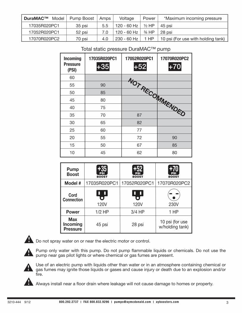
Do not spray water on or near the electric motor or control.
Pump only water with this pump. Do not pump flammable liquids or chemicals. Do not use the pump near gas pilot lights or where chemical or gas fumes are present.
Use of an electric pump with liquids other than water or in an atmosphere containing chemical or gas fumes may ignite those liquids or gases and cause injury or death due to an explosion and/or fire.
Always install near a floor drain where leakage will not cause damage to homes or property.
Incoming 17035R020PC1 17052R020PC1 17070R020PC2 Pressure (PSI)
60
55 90
50 85
45 80
40 75
35 70 87
30 65 82
25 60 77
20 55 72 90
15 50 67 85
10 45 62 80
+35 +52 +70
Total static pressure DuraMAC™ pump
NOT RECOMMENDED
PumpBoost
Model # 17035R020PC1 17052R020PC1 17070R020PC2
BOOSTPSI+35
BOOSTPSI+70
CordConnection
Power
MaxIncomingPressure
1/2 HP
120V 120V 230V
45 psi
1 HP
10 psi (for usew/holding tank)
3/4 HP
28 psi
BOOST
+52PSI
DuraMAC™ Model Pump Boost Amps Voltage Power *Maximum incoming pressure
17035R020PC1 35 psi 5.5 120 - 60 Hz ½ HP 45 psi
17052R020PC1 52 psi 7.0 120 - 60 Hz ¾ HP 28 psi
17070R020PC2 70 psi 4.0 230 - 60 Hz 1 HP 10 psi (For use with holding tank)

9/12 3210-4444 800.292.2737 | FAX 800.832.9296 | [email protected] | ayboosters.com
1. Apply pipe sealant on male threads of check valve. Thread into inlet of pump. DO NOT apply any pipe sealant on pump threads. Excessive pipe sealant or Teflon tape may foul check valves.
2. Make sure arrow on check valve is in the direction of flow. Push inside the check valve to make sure poppet can move. If the check valve is installed in the wrong direction water will not get into the pump.
3. Apply pipe sealant on the male threads of tailpiece. Install into outlet of pump. DO NOT apply any pipe sealant on pump threads.
4. Make sure the union nut is over the tailpiece before threading into pump.
5. O-ring should be installed in groove on top of tailpiece. Then tighten union nut to control tee.
6. Apply pipe sealant on male threads of tank bushing. Install into top of control.
7. Apply pipe sealant on tank threads and install into top of tank bushing. Only tighten with a wrench on the flats of the tank. The 2.1 Gallon tank included is required for this product to work properly. The air pressure of the tank must be set 2 psi less than the start pressure of the pump.
8. Plug the pump cable into the control cord. Do not plug the control into wall yet.Plugging in the control prior to making plumbing connections and priming the pump will cause the pump to run dry and void warranty.
9. Rotate control, so front panel and gauge are visible when installed.
10. Mount the pump base firmly, and follow piping instructions on next page.
CHECKVALVE
MUST CONNECT TO A GFCI PROTECTED CIRCUIT
CONTROLCORD
PUMPCORD UNION NUT
TAILPIECE
O-RING
TANK BUSHING15000 PC1 CONTROL
OR
INLET
OUTLET
TANK
FLOW
15000 PC2 CONTROL
MAGNETIC PISTONCONTROL TEE
3. PUMP ASSEMBLY
3210-444 9/12 5800.292.2737 | FAX 800.832.9296 | [email protected] | ayboosters.com
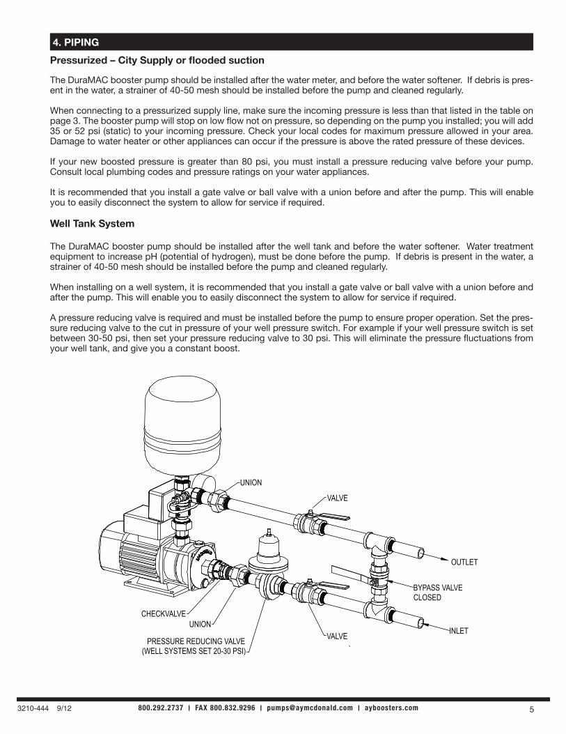
Pressurized – City Supply or flooded suction
The DuraMAC booster pump should be installed after the water meter, and before the water softener. If debris is pres-ent in the water, a strainer of 40-50 mesh should be installed before the pump and cleaned regularly.
When connecting to a pressurized supply line, make sure the incoming pressure is less than that listed in the table on page 3. The booster pump will stop on low flow not on pressure, so depending on the pump you installed; you will add 35 or 52 psi (static) to your incoming pressure. Check your local codes for maximum pressure allowed in your area. Damage to water heater or other appliances can occur if the pressure is above the rated pressure of these devices.
If your new boosted pressure is greater than 80 psi, you must install a pressure reducing valve before your pump. Consult local plumbing codes and pressure ratings on your water appliances.
It is recommended that you install a gate valve or ball valve with a union before and after the pump. This will enable you to easily disconnect the system to allow for service if required.
Well Tank System
The DuraMAC booster pump should be installed after the well tank and before the water softener. Water treatment equipment to increase pH (potential of hydrogen), must be done before the pump. If debris is present in the water, a strainer of 40-50 mesh should be installed before the pump and cleaned regularly.
When installing on a well system, it is recommended that you install a gate valve or ball valve with a union before and after the pump. This will enable you to easily disconnect the system to allow for service if required.
A pressure reducing valve is required and must be installed before the pump to ensure proper operation. Set the pres-sure reducing valve to the cut in pressure of your well pressure switch. For example if your well pressure switch is set between 30-50 psi, then set your pressure reducing valve to 30 psi. This will eliminate the pressure fluctuations from your well tank, and give you a constant boost.
4. PIPING
OUTLET
INLET
UNION
VALVE
CHECKVALVEUNION
PRESSURE REDUCING VALVE(WELL SYSTEMS SET 20-30 PSI)
(CITY SUPPLY - SEE INSTRUCTIONS)
VALVE
BYPASS VALVECLOSED

9/12 3210-4446 800.292.2737 | FAX 800.832.9296 | [email protected] | ayboosters.com
In holding tank applications, there are two methods for installing the pump. There is Flooded Suction and Suction lift. Both methods require correct sizing of the suction pipe. For the DuraMACTM Residential 20 GPM booster, the suction supply pipe must be 1” or larger. Using pipe diameters less then recommended, will cause cavitation and the pump to lose prime.
Flooded Suction is the preferred method because the pump will be fed with water under some pressure. The higher the water level is above the pump, the more incoming pressure will come from the tank. Every 28” of water height is equivalent to 1 psi. If the pump is more than 3 feet away from the tank, a stand pipe with a prime plug will help to prime the system.
HOLDING TANKS
HOLDING TANKS - FLOODED SUCTION
VALVECHECK VALVE
PUMP FILL PLUG
STAND PIPE
PRIME PLUG
UNION
FLOODED SUCTION PRIMING1. Remove pump fill plug and prime plug.2. Open tank valve.3. Fill water into pump until completly full.4. Install pump fill plug.5. Fill stand pipe with water until completly full.6. Install prime plug in stand pipe.7. Plug in pump and run water. The pressure gauge should read "PUMP BOOST" from table page 3, with discharge valves closed.8. Repeat priming if pressure is less.
STAND PIPE REQUIRED WHEN OVER 3 FEET
10
2030
40 50 6070
80
90100PSI

3210-444 9/12 7800.292.2737 | FAX 800.832.9296 | [email protected] | ayboosters.com
Suction Lift has the pump is located higher than the level of the water. The DuraMACTM booster can work in this application up to 20 feet, as long as the pump is fully primed. Air pockets and suction pipe leaks will cause the pump to accumulate air, and will eventually cause a Red light fault. However, if the pump inlet is the highest point, it is fully primed, a good check or foot valve is installed, a standard pipe is installed, and there are no suctions leaks, the pump will perform well.
The pump inlet must also be the highest point. There can be no humps in the line as shown here:
The DuraMACTM has the advantage over a Jet pump of being more efficient and quieter, however a Jet pump has the advantage of always priming itself. When installed and primed properly, the DuraMACTM booster will work well in holding tank applications.
HOLDING TANKS - SUCTION LIFT
SUCTION LIFT
UNION
PRIME PLUG
STAND PIPE
PUMP FILL PLUG
CHECK VALVE VALVE
PRIMINGInstall the check or foot valve by the tank, not in the pump.1. Remove the pump fill plug and prime plug.2. Fill water into standpipe until water spills out of pump.3. Install pump fill plug.4. Fill standpipe with additional water until full.5. Install prime plug in standpipe.6. Plug in pump and run water. The pressure gauge should read "PUMP BOOST" from table page 3, with discharge valve closed.7. Repeat priming if pressure is less.
Pump inlet must be the highest point.
SUCTION PIPE
OUTLET
FOOT VALVE
PRIME PLUG
STAND PIPE
PUMP FILL PLUG
PSI 10090
8070
60504030
20
10
VALVECHECK VALVE
PUMP FILL PLUG
STAND PIPE
PRIME PLUG
UNION
WILL NOT WORK -AIR POCKET IN HOSE
Pump inlet must be the highest point. Humps in suction hoses will never work.Raise pump if needed.
10
2030
40 50 6070
80
90100PSI

9/12 3210-4448 800.292.2737 | FAX 800.832.9296 | [email protected] | ayboosters.com
This control accurately measures pressure with a pressure transducer and starts the pump at an adjustable start pressure point. The pump will stop when the flow is less than ½ a gallon per minute.
This smart system will only run the pump when water is in use. There is a preset 7 second delay after water is not flowing past the internal flow sensor to fully pressurize your sys-tem and eliminate water hammer.
If the pump fails to build pressure, there is an automatic feature that will try to restart the pump every 15 minutes after a failure. This will occur automatically 4 times, flashing one time for every failed restart, then a flashing RED fault light will be on. This will protect your pump from running dry if the water supply is in-adequate.
Boosting- Start Up
Do not plug in the control power cord into the wall outlet until Step 2 below is complete.
After all the pipe connections are made as shown in Section 4: 1. Open water main shutoff valve slowly and check for leaks. 2. Open a nearby faucet and let water flow through for about 1 minute or until all the air is purged from the pipes. This is necessary to prime the pump. 3. With the faucet open, plug in the control power cord. The pump should run, if not press the RESET button, the blue light should be on and the pressure gauge should increase. 4. Close faucet. The pump will run for 7 seconds after the flow has stopped. The green stand by light should be on. 5. Remove the round dial cover and adjust dial on the control 10 – 15 psi less than the pressure shown on gauge. Push the Reset button. 6. The air pressure in the tank should be 2 psi less than the start pressure on the control dial. If the tank is not mounted on the brass control tee, it should be no further than 10 feet away. 7. In order to check the air pressure in the tank, shut off the water supply main valve, open a faucet. The pressure gauge on the control should be reading zero. With a tire pressure gauge check the pressure in the top of the tank. Pressurize the tank as required with a tire pump or air compressor. See diagram on the next page. 8. Open main shut off valve then close faucet. Check for leaks.
10
20
3040
50
60
700
SET 10-15 PSI BELOWBOOSTED PRESSURE
PUSH RESET
START PRESSURE
STAND BY FAULTRUNRESET
FLOW
PUMP STARTS ON PRESSUREPUMP STOPS ON LOW FLOWSTART PRESSURE INSTRUCTIONSUNDER ROUND COVERTO CLEAR A FAULT, CHECK FOR FLOW, THEN DECREASE START PRESSURE AND PUSH RESETAIR PRESSURE IN TANK SHOULD BE2 PSI LESS THAN START PRESSUREFOR INDOOR USE ONLY
15000 PC1 DuraMAC PUMP CONTROL120VAC 60HZ 10 FLA 60 LRA
WWW.AYBOOSTERS.COM
TM
PRESSURE MODESTART METHOD: Pressure DropSTOP METHOD: Low Flow
5. PUMP CONTROL - STANDARD MODE

3210-444 9/12 9800.292.2737 | FAX 800.832.9296 | [email protected] | ayboosters.com
Your pump controller can also be setup to start and stop on flow only. This is not intended to work in suction lift applications. This method can be used for situations such as minor leaking or when incoming pressure is varying or higher incoming pressures. The starting flow rate exceeds approximately 1 Gallon per Minute. The stopping flow rate is about ½ a Gallon per Minute. There must be at least 25 psi incoming pressure at the highest fixture for this to work properly. Once the pressure in the tank has dropped to the incoming pressure there is a 3 second delay until the pump starts. The green light will be flashing. This is to prevent a false start caused by fluctuating pressure in the supply line.
1. Turn the Start Pressure dial to “0” and push RESET. Now the pump will start and stop with flow. 2. Adjust air pressure in tank. The tank pressure should be 2 psi lower than the start pressure. You will need to watch your pressure gauge when water is flowing to see the pressure where the pump starts.
Your pump controller can be set to save electricity by running only during peak demands. The pump will operate only when system pressure is below city supplied pressure and operates continuously while there is demand for water. 1. Turn the Start Pressure dial 5 to 10 psi below incoming city pressure and push RESET. Now the pump will start when the pressure drops below the incoming pressure. 2. Adjust air pressure in tank (see #6-7 on page 7)
25
3.5
11.2
8ADD AND MEASURE AIR PRESSURE HERE NOTE: WATER PRESSURE MUST BE 0 PSI
16.5
4 5.5 4.25
1"Male NPT
1"Female NPT
6. ALTERNATIvE PUMP CONTROL MODES
FLOW MODESTART METHOD: Water FlowSTOP METHOD: Low Flow
CONSERvATION MODESTART METHOD: Pressure dropSTOP METHOD: Low Flow
NOTE: Not all modes are ideal for every application.

9/12 3210-44410 800.292.2737 | FAX 800.832.9296 | [email protected] | ayboosters.com
RED light on (or flashing) and pump will not start:
1. Start pressure set to high. Remove round cover on control and adjust start pressure dial 10 – 15 psi less than maximum boosted pressure as shown on pressure gauge, and push RESET. This unit is factory set at 50 psi. If red light faults still occur, turn down start pressure dial an additional 5-10 psi. Then adjust air pressure in tank (see #6 on page 7).
2. Water cannot flow through pump to build pressure. Make sure all valves are open and the check valve is in the correct orientation.
3. If installed in a suction lift application, prime could be lost. Re-prime and check for leaks on suction side. Push the RESET button, the pump will run for 5 seconds, watch pressure gauge to make sure that the pressure is increasing.
4. Make sure all filters are installed after the pump, change the filter cartridges regularly.
5. This can occur if the water supply has been interrupted. The pump will automatically try a restart 15 minutes after a failure. This will occur automatically 4 times, flashing one time for every failed restart, and then a solid RED light will be on.
BLUE light on and pump will not stop:
1. Pump stops on a flow rate less than ½ GPM. This is normal if flow is higher.
2. Possible leaks in systems such as; running toilets, humidifiers, water softeners, ice makers…
3. If the pump has a bypass valve installed, make sure it is closed for normal operation (see diagram page 5).
4. Plastic magnetic piston (inside brass control) could be jammed by excessive thread sealant or debris. Loosen union nut and inspect piston. It should move freely and spring outwards (see diagram page 4).
5. To check for water leakage in the house, close the valve after pump. If pump stops, then water is leaking somewhere after this valve. Fix leaks and open valves again.
Pump starts and stops without obvious use:
1. Small leaks in the system can cause this. Reduce Start Pressure by turning dial to a lower pressure. Then adjust air pressure in tank (see #6 on page 7).
2. Try alternate Flow Mode page 8.
GREEN light on and pump will not start:
1. Start pressure dial set lower than incoming pressure. Adjust start pressure dial 10 – 15 psi less than maximum boosted pressure as shown on pressure gauge, and push reset. Then adjust air pressure in tank see #6 on page 7.
Pump stops at a pressure higher than 80 psi.
1. This can happen if your incoming pressure is higher than the value in the table on page 3. A Pressure reducing valve should be installed before the pump.
7. TROUBLESHOOTING

3210-444 9/12 11800.292.2737 | FAX 800.832.9296 | [email protected] | ayboosters.com
Pump will not start and no lights are on.
1. Make sure pump is plugged into control, and control is plugged into a GFCI circuit. Test wall power receptacle with a light or multi-meter.
2. Unplug gray transducer cable, turn start pressure dial to “0” and push reset (Flow Mode). If a light comes on, contact customer service.
If Pump Is Noisy:
1. Be sure the pump is mounted on a substantial foundation. Pipe should be rigid and all connections tight. 2. Total suction lift or flow is beyond the pump capability and the pump is starved for water.
Pump will not stay primed (Suction lift).
1. Check foot valve. Make sure it is clean and sufficiently submerged; but is not in sand or mud. 2. Be sure pump is sufficiently primed. 3. Check for possible leaks in suction piping. 4. Total suction lift may be beyond the pump capability of 20 feet.
7. TROUBLESHOOTING - CONT’D
