durable and sustainable overlay with ecc
TRANSCRIPT

Durable and sustainable overlay with ECC Shunzhi Qian1,2, Victor C. Li1, Han Zhang3 and Gregory A. Keoleian3
Abstract While Portland cement concrete (PCC) overlay has been increasingly used as a rehabilitation technique for deteriorated PCC pavements in the last decade, reflective cracking places a major limit on its durability performance. The use of ultra ductile concrete named Engineered Cementitious Composite (ECC) should arrest such failure mode and greatly enhance the long term performance of the overlaid pavements. In this paper, we introduce and demonstrate this novel concept via experimental study on the reflective cracking resistance of small-scale ECC overlaid concrete beam. The ECC specimens totally eliminate the reflective cracking mode by developing extensive micro-cracks under flexural fatigue loading, in addition to a much enhanced MOR compared to controlled concrete specimen. Based on FEM analysis of the overlay system and fatigue performance of the ECC beam, a simplified design chart for ECC overlay is presented for use in practice and LCA-LCC analysis. The proposed ductile overlay approach should greatly enhance the durability and sustainability of the future pavement overlay. Introduction Unbonded concrete overlay and HMA overlay are two major rehabilitation methods used for deteriorated rigid pavements (MDOT 2005). In both cases, reflective cracking acts as a major limitation on the service life of overlays (Tayabji and Okamoto 1985; Huang 2004). Under repeated traffic loading, the preexisting joints/cracks in the substrate concrete tend to reflect through the overlay, ultimately leading to the termination of service life of the overlaid concrete pavement. The overlay material responds brittlely under high stress concentration induced by the preexisting joint/crack in the substrate concrete. A number of techniques addressing the reflective cracking problem have been attempted with varying degrees of success. Current Techniques to Addressing Reflective Cracking and Limitations. Current techniques may be grouped into at least three broad categories in relation to their different approaches to address reflective cracking: concrete slab fracturing, stress-relieving (crack relief) interlayer, and modified overlay. Concrete slab fracturing techniques include rubblization, crack and seat (for plain concrete pavement), and break and seat (for reinforced concrete pavement). By creating small pieces of concrete, fracturing technique minimizes one of the main mechanisms of reflective cracking, i.e., the horizontal movement of concrete substrate due to temperature and moisture changes (Huang 2004). The second broad category involves paving fabric, geogrid, and specially modified HMA interlayer. These interlayers are used in between the concrete substrate and the HMA overlay and/or concrete overlay to 1 ACE-MRL, Dept. of Civil and Environ. Engineering, University of Michigan, MI 48109, USA 2 Now at Microlab, Dept. of Civil Eng. and Geoscience, T U Delft, 2600 GA, Delft, The Netherlands 3 CSS, School of Natural Resources and Environ., University of Michigan, MI 48109, USA
9th International Conference on Concrete Pavements, San Francisco, California, August 17-21, 2008 918

relieve the stress/strain concentration. The third category – the modified overlay technique, involves addition of fiber reinforcement in the overlay, introduction of saw and seal joints (in a HMA overlay), and increasing the overlay thickness.
If used appropriately, most of the current techniques can delay, although not totally eliminate the initiation of reflective cracking. However, a number of drawbacks are associated with different techniques. These are briefly summarized below. Among the three slab fracturing techniques, rubblization is generally considered to be a more favorable approach to reduce reflective cracking through its smaller concrete pieces (DelDOT 2002). Yet, greater overlay thickness is required to compensate for the reduction in structural capacity caused by fracturing the concrete (FHWA 1987; Freeman 2002)). The experience with stress-relieving interlayers is somewhat controversial; depending on the site condition, thickness of overlay, and installation workmanship, the results may vary greatly (Blankenship et al 2004; Amini 2005). Additionally, the cost of some of the proprietary interlayers is prohibitive (Chen 2006). In the third category, fiber reinforced overlay shows limited success (Jiang and McDaniel 1993; MoDOT 2000). Significant reflective cracking and/or spalling may occur when relatively thin overlay is used (Marks 1989; Smith 2001). As for the saw and seal joints method, the state DOTs that documented their experience with this method reported marginal to good results (Kilareski and Bionda 1990; Hall et al 2003). The presence of joints may necessitate additional maintenance. Thickening an overlay is not necessarily cost-effective and sometimes cannot effectively reduce the reflective crack intensities (Jiang and McDaniel 1993). Despite their effect of delaying the initiation of reflective cracking, none of the current techniques can totally eliminate reflective cracking and greatly extend service life, which is critical to reduce the life cycle cost especially when user delay costs are considered (Morian and Gibson 1998). For example, according to the Illinois DOT (Lippert 2003), on average HMA overlay with rubblized concrete pavement can extend service life for 1-2 years with better performance compared to control sections without rubblization. This amount of extension in service life is beneficial, yet not significant considering continuously aging US highway infrastructure and shrinking funding for repair and rehabilitation of the highway infrastructure. A more reliable and robust approach is needed to fully address the reflective cracking problem in order to greatly extend the service life and simultaneously minimize maintenance requirements, therefore resulting in a durable and sustainable overlay system.
. 0
1
2
3
4
5
6
7
0 1 2 3 4 5Tensile strain (%)
Tens
ile st
ress
(MPa
) .
Figure 1 Typical tensile stress-strain curve of ECC (1MPa=145psi)
9th International Conference on Concrete Pavements, San Francisco, California, August 17-21, 2008 919

Ductile Concrete Overlay Approach. To resolve the reflective cracking problem, a material-based solution is investigated to eliminate overlay fracture localization reflecting upward from a concrete substrate. Specifically, in this study, a polyvinyl alcohol (PVA) fiber reinforced ECC designed for ultra high ductility and damage tolerance is proposed to replace the HMA/concrete in the rigid pavement overlay. With tensile strain capacity approaching 300 times that of normal concrete (Figure 1), this approach directly builds-in a mechanically auto-adaptive behavior in which the ECC steps down in material stiffness by undergoing an elastic-inelastic transition when overstressed in tension/bending, but without giving up the load-carrying capacity. This proposed solution exploits the ultra ductility and high damage tolerance of ECC, without relying on slab fracturing, stress relieving interlayers, or other measures. It is expected that this material ductility approach is able to totally suppress reflective cracking in pavement overlays. As a result, ECC overlay can be potentially more cost-effective compared with current approaches due to expected reduced thickness, minimized maintenance and greatly extended service life.
Given the above consideration, this investigation will first verify and/or demonstrate the reflective cracking resistance of ECC overlaid concrete beam under fatigue loading. Furthermore, focus will then be put on the examination of the flexural performance of ECC materials under fatigue loading (σ-N curve), along with FEM analysis of ECC overlaid rigid pavement to reveal the influence of overlay thickness on the structural response (σ-h curve). From these investigations, a fatigue stress – fatigue life (σ-N) relation and a maximum tensile stress – overlay thickness (σ-h) relation is obtained (Figure 2). Combining these relations results in an overlay thickness – fatigue life (h-N) relation. This relation provides design guideline for future ECC overlay field application and also facilitates the life cycle analysis of the rigid pavement overlay incorporating ECC materials.
σ
hh1
σ1
σ2
Concrete
ECC
h1
N1
h
NN2
Concrete
ECC
h2 Design Chart
σ
N
N1 N2
Concrete
ECC
h σ
FEM Analysis
Beam Fatigue
Test
Figure 2 Integration of FEM analysis and material fatigue test result
9th International Conference on Concrete Pavements, San Francisco, California, August 17-21, 2008 920

Table 1 Mix proportion of concrete, ECC M45 and HVFA ECC
fc’
(MPa) εu
(%) C S A FA W SP PVA Fiber
Concrete 60.6 0.01 1.0 2.0 2.0 0 0.45 0 0 ECC M45 54.6 2.5 1.0 0.8 0 1.2 0.59 0.013 0.02
HVFA-ECC 37.5 3.7 1.0 1.41 0 2.8 0.99 0.015 0.02
(Note: fc’ is compressive strength; εu is the tensile strain capacity; C is cement; S is
sand; A is coarse aggregate for concrete and silica sand for ECC; FA is fly ash; W is water; SP is superplasticizer; 1MPa=145psi) Reflective cracking resistance of ECC overlay Experimental preparation. ECC M45 and high volume fly ash (HVFA) ECC were investigated in this study as overlay materials, as revealed in Table 1. In addition to ECCs, concrete was also used as overlay for comparison purpose. As can be seen from the table, the two ECCs have average strain capacity of 2.5 and 3.7%, about 250 and 370 times that of concrete. The compressive strength of Concrete is comparable to that of ECC 1 while significantly higher than that of ECC 2.
The geometry for 1/4 scaled concrete overlay specimen (in thickness) is adopted from Zhang and Li (2002) except the newly introduced HMA interlayer (13mm thick) in the overlay specimen, simulating the current common practice in concrete overlay construction. The concrete substrate has a dimension of 356mm long, 51 mm thick and 76 mm deep, with a span between two supports of 305mm. The concrete overlay has a thickness of 38 mm. Four point bending test was conducted at a constant moment span length of 152mm.
The thickness of ECC is 25 mm, significantly lower compared with that of concrete. Additionally, it is expected that the ECC can suppress the reflective cracking completely by its ductile response, without relying on an HMA interlayer. The initial horizontal debonding zone used in Zhang and Li (2002) is also removed in order to create an even more severe stress concentration for the ECC overlay.
The concrete substrate was cast and the surface tined by a rake before the concrete is hardened to simulate the surface texture for pavement. After wet curing for 28 days, the substrate was then cut into two halves to represent the preexisting crack in the concrete substrate. The concrete substrate was again put into a mold and covered by a compacted layer of HMA (13 mm thick). Finally the concrete overlay was poured on top of the HMA interlayer. In the case of ECC, no HMA interlayer was applied and ECC was directly poured on top of the concrete substrate. In both cases, the finished specimens were cured in sealed container for 28 days.
The composite MOR (flexural strength) was determined using the maximum load measured and elastic beam theory. The monotonic test was conducted under displacement control at a rate of 0.1mm/minute according to ASTM C 1018. Once the flexural strength was obtained from monotonic test, the fatigue test started using load control with sinusoidal waveform at a frequency of 8 Hz. The corresponding flexural stress and fatigue life was recorded to obtain σ-N relation for overlay systems.
9th International Conference on Concrete Pavements, San Francisco, California, August 17-21, 2008 921
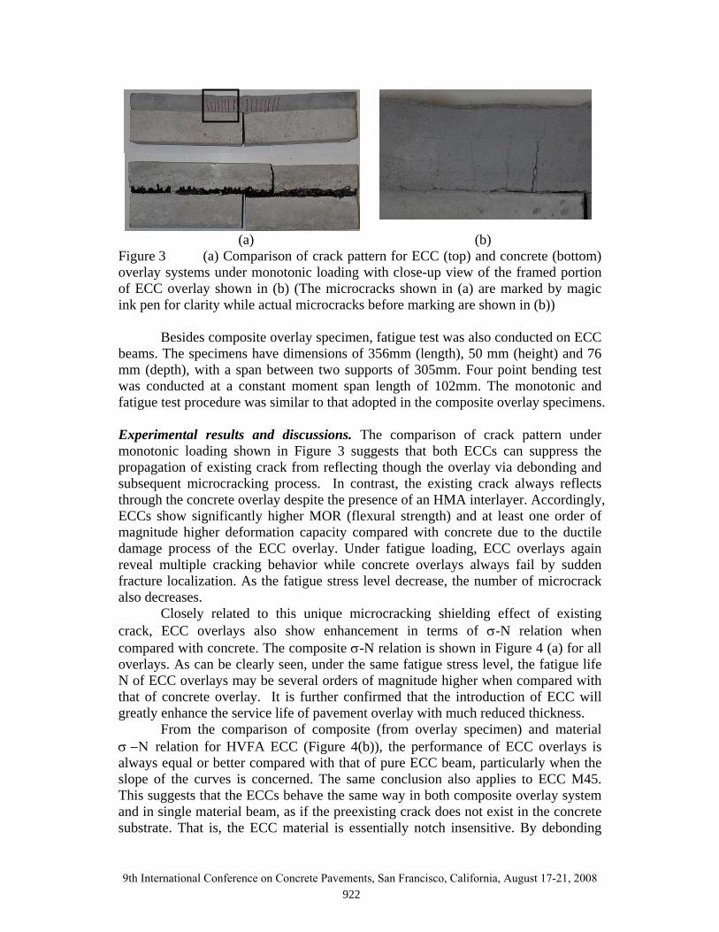
(a) (b) Figure 3 (a) Comparison of crack pattern for ECC (top) and concrete (bottom) overlay systems under monotonic loading with close-up view of the framed portion of ECC overlay shown in (b) (The microcracks shown in (a) are marked by magic ink pen for clarity while actual microcracks before marking are shown in (b))
Besides composite overlay specimen, fatigue test was also conducted on ECC beams. The specimens have dimensions of 356mm (length), 50 mm (height) and 76 mm (depth), with a span between two supports of 305mm. Four point bending test was conducted at a constant moment span length of 102mm. The monotonic and fatigue test procedure was similar to that adopted in the composite overlay specimens. Experimental results and discussions. The comparison of crack pattern under monotonic loading shown in Figure 3 suggests that both ECCs can suppress the propagation of existing crack from reflecting though the overlay via debonding and subsequent microcracking process. In contrast, the existing crack always reflects through the concrete overlay despite the presence of an HMA interlayer. Accordingly, ECCs show significantly higher MOR (flexural strength) and at least one order of magnitude higher deformation capacity compared with concrete due to the ductile damage process of the ECC overlay. Under fatigue loading, ECC overlays again reveal multiple cracking behavior while concrete overlays always fail by sudden fracture localization. As the fatigue stress level decrease, the number of microcrack also decreases.
Closely related to this unique microcracking shielding effect of existing crack, ECC overlays also show enhancement in terms of σ-N relation when compared with concrete. The composite σ-N relation is shown in Figure 4 (a) for all overlays. As can be clearly seen, under the same fatigue stress level, the fatigue life N of ECC overlays may be several orders of magnitude higher when compared with that of concrete overlay. It is further confirmed that the introduction of ECC will greatly enhance the service life of pavement overlay with much reduced thickness.
From the comparison of composite (from overlay specimen) and material σ −Ν relation for HVFA ECC (Figure 4(b)), the performance of ECC overlays is always equal or better compared with that of pure ECC beam, particularly when the slope of the curves is concerned. The same conclusion also applies to ECC M45. This suggests that the ECCs behave the same way in both composite overlay system and in single material beam, as if the preexisting crack does not exist in the concrete substrate. That is, the ECC material is essentially notch insensitive. By debonding
9th International Conference on Concrete Pavements, San Francisco, California, August 17-21, 2008 922

and subsequent microcracking process, the stress concentration induced by the existing crack is diffused in the ECC overlay. This observation demonstrated the excellent reflective crack resistance behavior for ECC and the material σ −Ν relation can be conservatively utilized in ECC overlay design. Figure 4 Comparison of flexural stress – number to fatigue failure (σ −Ν) relation for (a) different overlay systems and (b) ECC overlay and ECC beam (1MPa=145psi)
In case of concrete overlay, Figure 5 indicates the positive effect of HMA
interlayer for concrete overlay, even though its final failure is still governed by reflective cracking along with lower performing σ −Ν relation compared with that of ECC overlays. Besides concrete overlay investigated in this investigation, concrete overlay from Li et al (2006) are also plotted for comparison. It should be noted that concrete overlay in their study did not include the HMA interlayer, therefore the slope of their σ −Ν curve is significantly steeper compared with concrete overlay in this study. In addition, concrete beam fatigue test results from Yao (1997) and Oh (1991) are also plotted as reference. It can be seen that the slope of concrete overlay with HMA overlay in this study have about same slope with that of concrete beam σ −Ν curves.
0
24
68
1012
1416
18
1 10 100 1000 10000 100000 1E+06Number to failure
Flex
ural
stre
ss (M
Pa)
ECC OL (HVFA)ECC beam (HVFA)
02
468
101214
1618
1 10 100 1000 10000 100000 1000000Number to failure
Flex
ural
stre
ss (M
Pa)
ECC (M45)ECC (HVFA)Concrete
(a)
(b)
9th International Conference on Concrete Pavements, San Francisco, California, August 17-21, 2008 923
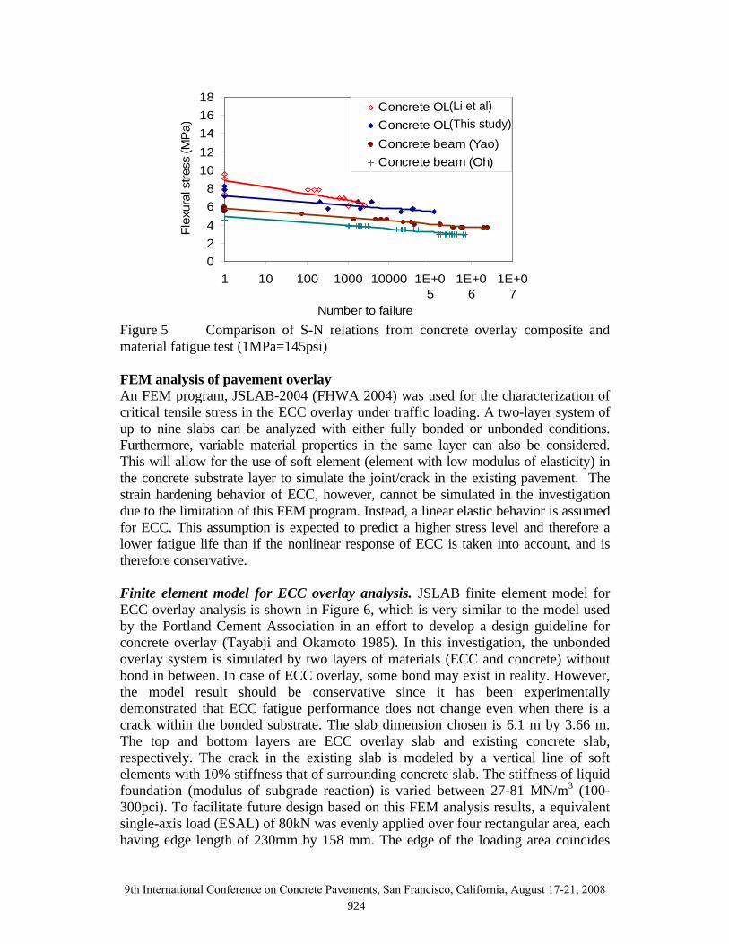
Figure 5 Comparison of S-N relations from concrete overlay composite and material fatigue test (1MPa=145psi) FEM analysis of pavement overlay An FEM program, JSLAB-2004 (FHWA 2004) was used for the characterization of critical tensile stress in the ECC overlay under traffic loading. A two-layer system of up to nine slabs can be analyzed with either fully bonded or unbonded conditions. Furthermore, variable material properties in the same layer can also be considered. This will allow for the use of soft element (element with low modulus of elasticity) in the concrete substrate layer to simulate the joint/crack in the existing pavement. The strain hardening behavior of ECC, however, cannot be simulated in the investigation due to the limitation of this FEM program. Instead, a linear elastic behavior is assumed for ECC. This assumption is expected to predict a higher stress level and therefore a lower fatigue life than if the nonlinear response of ECC is taken into account, and is therefore conservative. Finite element model for ECC overlay analysis. JSLAB finite element model for ECC overlay analysis is shown in Figure 6, which is very similar to the model used by the Portland Cement Association in an effort to develop a design guideline for concrete overlay (Tayabji and Okamoto 1985). In this investigation, the unbonded overlay system is simulated by two layers of materials (ECC and concrete) without bond in between. In case of ECC overlay, some bond may exist in reality. However, the model result should be conservative since it has been experimentally demonstrated that ECC fatigue performance does not change even when there is a crack within the bonded substrate. The slab dimension chosen is 6.1 m by 3.66 m. The top and bottom layers are ECC overlay slab and existing concrete slab, respectively. The crack in the existing slab is modeled by a vertical line of soft elements with 10% stiffness that of surrounding concrete slab. The stiffness of liquid foundation (modulus of subgrade reaction) is varied between 27-81 MN/m3 (100-300pci). To facilitate future design based on this FEM analysis results, a equivalent single-axis load (ESAL) of 80kN was evenly applied over four rectangular area, each having edge length of 230mm by 158 mm. The edge of the loading area coincides
02468
1012141618
1 10 100 1000 10000 1E+05
1E+06
1E+07
Number to failure
Flex
ural
stre
ss (M
Pa)
Concrete OL (Mo Li)Concrete OLConcrete beam (Yao)Concrete beam (Oh)
(Li et al) (This study)
9th International Conference on Concrete Pavements, San Francisco, California, August 17-21, 2008 924

with the long edge of the overlay slab. The maximum tensile stresses at the bottom of the overlay slab directly underneath the loaded edge thus determined are summarized below. Figure 6 FEM Model of overlay system with existing cracked concrete substrate
02468
1012141618
0 50 100 150 200 250 300Overlay thickness (mm)
Ove
rlay
max
stre
ss (M
Pa)
Concrete
ECC
Figure 7 Overlay slab maximum tensile stress with overlay thickness relation for concrete and ECC (concrete substrate modulus = 20.7 GPa and k = 27.1 MN/m3, Cracked substrate of 250 mm assumed; 1MPa=145psi, 1mm=0.04inch) Analysis results and discussions. The influence of overlay material property (modulus of elasticity) on the overlay maximum tensile stress with overlay thickness relation was investigated first. The concrete and ECC overlay have modulus of elasticity of 34.5 GPa and 20.7 GPa, respectively. As shown in Figure 7, the maximum tensile stress induced in the ECC overlay is smaller compared with that of concrete overlay due to reduced modulus of elasticity.
Additionally, the effect of the subgrade quality (modulus of subgrade reaction: k) on the ECC overlay maximum tensile stress with overlay thickness relation was also investigated. The results reveal that the maximum tensile stress with overlay thickness relation shifted downward when k increases. This suggests
9th International Conference on Concrete Pavements, San Francisco, California, August 17-21, 2008 925
that high quality subgrade is important in the case of ECC overlay application, particularly in the case of thin ECC overlays.
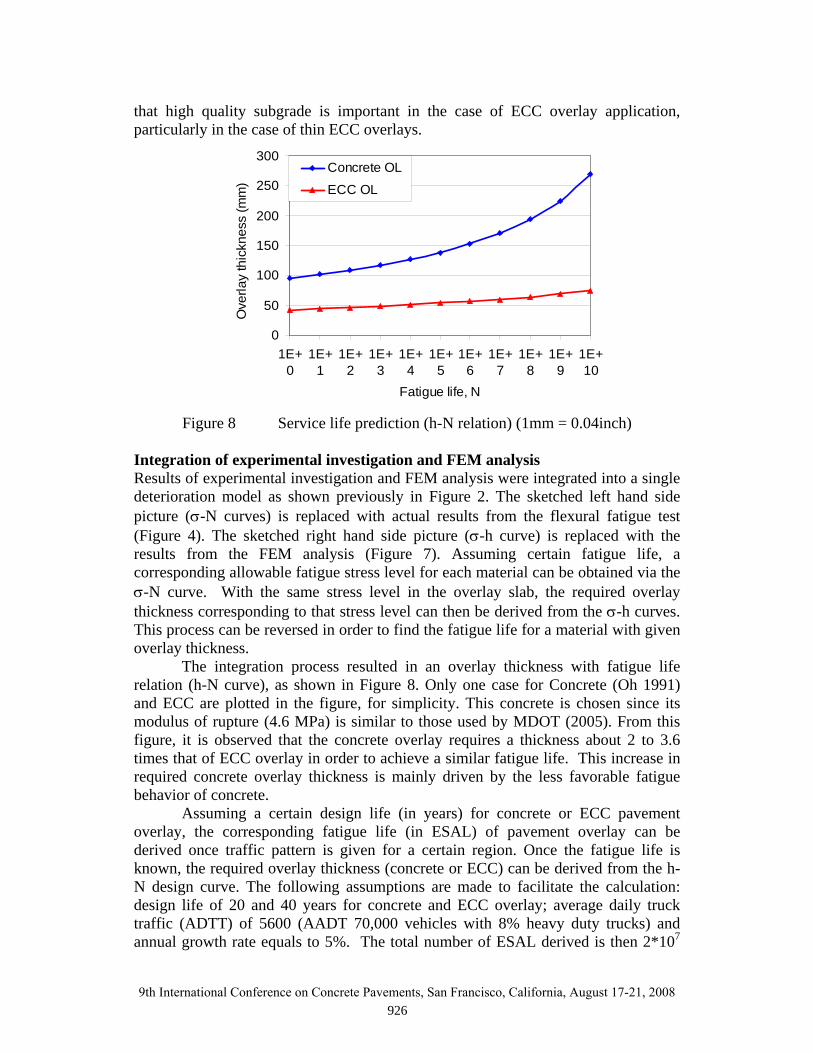
Figure 8 Service life prediction (h-N relation) (1mm = 0.04inch) Integration of experimental investigation and FEM analysis Results of experimental investigation and FEM analysis were integrated into a single deterioration model as shown previously in Figure 2. The sketched left hand side picture (σ-N curves) is replaced with actual results from the flexural fatigue test (Figure 4). The sketched right hand side picture (σ-h curve) is replaced with the results from the FEM analysis (Figure 7). Assuming certain fatigue life, a corresponding allowable fatigue stress level for each material can be obtained via the σ-N curve. With the same stress level in the overlay slab, the required overlay thickness corresponding to that stress level can then be derived from the σ-h curves. This process can be reversed in order to find the fatigue life for a material with given overlay thickness.
The integration process resulted in an overlay thickness with fatigue life relation (h-N curve), as shown in Figure 8. Only one case for Concrete (Oh 1991) and ECC are plotted in the figure, for simplicity. This concrete is chosen since its modulus of rupture (4.6 MPa) is similar to those used by MDOT (2005). From this figure, it is observed that the concrete overlay requires a thickness about 2 to 3.6 times that of ECC overlay in order to achieve a similar fatigue life. This increase in required concrete overlay thickness is mainly driven by the less favorable fatigue behavior of concrete.
Assuming a certain design life (in years) for concrete or ECC pavement overlay, the corresponding fatigue life (in ESAL) of pavement overlay can be derived once traffic pattern is given for a certain region. Once the fatigue life is known, the required overlay thickness (concrete or ECC) can be derived from the h-N design curve. The following assumptions are made to facilitate the calculation: design life of 20 and 40 years for concrete and ECC overlay; average daily truck traffic (ADTT) of 5600 (AADT 70,000 vehicles with 8% heavy duty trucks) and annual growth rate equals to 5%. The total number of ESAL derived is then 2*107
0
50
100
150
200
250
300
1E+0
1E+1
1E+2
1E+3
1E+4
1E+5
1E+6
1E+7
1E+8
1E+9
1E+10
Fatigue life, N
Ove
rlay
thic
knes
s (m
m) .
Concrete OL
ECC OL
9th International Conference on Concrete Pavements, San Francisco, California, August 17-21, 2008 926
and 8*107 based on above traffic pattern and design life for concrete and ECC OL, respectively. It should be noted that the total number of ESAL increases exponentially with the service life due to the effect of annual growth rate. From the h-N design curves, the required overlay thickness for concrete and ECC is about 175 mm and 65 mm, respectively. The typical range of overlay thickness used in Michigan is about 150 to 200 mm with a design life of about 20 years according to MDOT (2005). Hence the model prediction for concrete overlay agrees reasonably well with current practice in Michigan. While assumed 40 years service life for ECC overlay is mainly based on its greatly improved reflective cracking resistance, the longer service life should also be assured by the durability enhancement of ECC in freeze thaw and salt scaling test (Sahmaran and Li 2007).
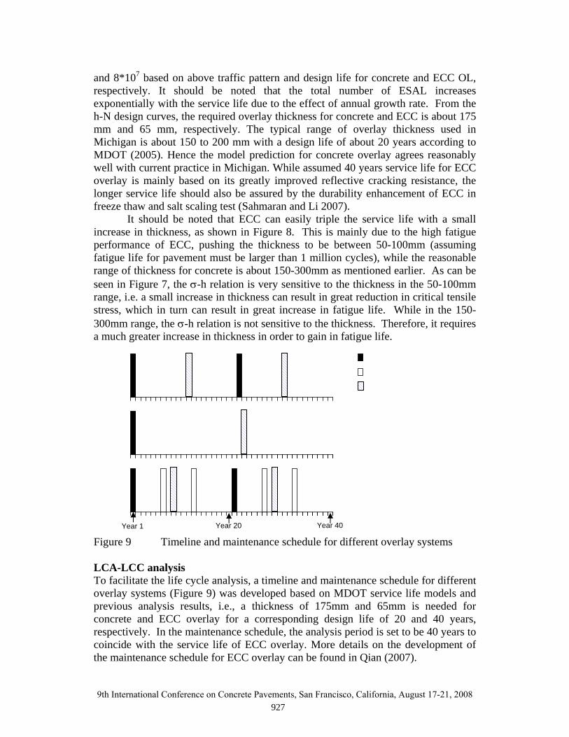
It should be noted that ECC can easily triple the service life with a small increase in thickness, as shown in Figure 8. This is mainly due to the high fatigue performance of ECC, pushing the thickness to be between 50-100mm (assuming fatigue life for pavement must be larger than 1 million cycles), while the reasonable range of thickness for concrete is about 150-300mm as mentioned earlier. As can be seen in Figure 7, the σ-h relation is very sensitive to the thickness in the 50-100mm range, i.e. a small increase in thickness can result in great reduction in critical tensile stress, which in turn can result in great increase in fatigue life. While in the 150-300mm range, the σ-h relation is not sensitive to the thickness. Therefore, it requires a much greater increase in thickness in order to gain in fatigue life. Figure 9 Timeline and maintenance schedule for different overlay systems LCA-LCC analysis To facilitate the life cycle analysis, a timeline and maintenance schedule for different overlay systems (Figure 9) was developed based on MDOT service life models and previous analysis results, i.e., a thickness of 175mm and 65mm is needed for concrete and ECC overlay for a corresponding design life of 20 and 40 years, respectively. In the maintenance schedule, the analysis period is set to be 40 years to coincide with the service life of ECC overlay. More details on the development of the maintenance schedule for ECC overlay can be found in Qian (2007).
Year 40Year 20Year 1
9th International Conference on Concrete Pavements, San Francisco, California, August 17-21, 2008 927

In the case of ECC OL, the maintenance schedule assumes there is only one major repair event in the middle of its service life. This assumption is warranted since the reflective cracking resistance of ECC was already demonstrated and much extended joint spacing is expected the ECC OL, considering major repair for UBOL includes joint resealing, crack sealing, joint/crack associated concrete patch repairs, and dowel bar retrofit. Due to its extremely high tensile strain capacity (typically 3% or more) capable of accommodating temperature and shrinkage effects (0.1% (Lepech 2006)), it is very likely that ECC can greatly extend the joint spacing and/or even totally eliminate the expansion joint. A similar idea has been demonstrated in a bridge deck link slab in Michigan (2006) and a completely jointless ECC/steel composite bridge deck in Japan (Li 2005). From the above discussions, it seems logical to assume that less frequent repair (once in service life) is needed for ECC OL. The minor and major repair for HMA overlay mainly involves pothole repair and thin layer overlay, respectively.
As aforementioned, a complete life-cycle model was used to evaluate overall sustainability performance for different overlay systems (Zhang et al 2007). This analysis incorporated all components of service life. Life cycle analysis and modeling work has been undertaken by Keoleian and co-workers (Keoleian et al 2005; Lepech et al 2005). The life cycle assessment includes the following sub-models: material production model, construction model, distribution model, traffic model and fuel economy model. Only the results from their analysis will be presented in following section. The readers are referred to Zhang et al (2007) for more details regarding LCA-LCC analysis.
Analysis of material production energy impacts reveals that due to the higher cement content and petroleum energy embodied within the PVA fibers, ECC requires 220% more energy to produce per cubic meter of material than plain concrete. Similar results are obtained for global warming potential, and other environmental indicators. While this very high environmental burden is alarming, only by examining the full life cycle of ECC material in a specific infrastructure application, such as an ECC overlay, can a complete assessment be made.
Total Primary Energy Consumption
0
0.5
1
1.5
2
2.5
Concrete ECC HMA
106 G
J
End-of-LifeDistribution
MaterialsConstruction
UsageCongestion
Figure 10 Total primary energy consumption for different overlay systems (1 Joule = 8.85 inch pound)
9th International Conference on Concrete Pavements, San Francisco, California, August 17-21, 2008 928

Building from ECC overlay service life model along with construction data, user data, and national agency and social discount rates, a full assessment of ECC material within the overlay system shows significant benefits for using ECC (Zhang et al 2007) (Figures 10 and 11). Due to the greatly reduced thickness, much extended service life and less frequent repair events, ECC overlay were found to reduce total primary energy consumption by 75% compared with HMA overlay and slightly less than concrete overlay even though its material energy intensity (MJ/m3) is more than three times that of concrete. Similarly, the global warming index is reduced by 32 to 37% compared with concrete and HMA overlay. The results from Zhang et al (2007) suggest that ECC overlay system performs significantly better compared with the other two overlay systems in most of the categories, such as PM10, SOx, Ammonia, etc. These results suggest that the comparison of sustainability of different materials can only be meaningful from the system viewpoint.
Figure 11 Global warming index of different overlay systems (1 kg=2.2 lb.)
Table 2 Comparison of life cycle cost for different overlay systems
Concrete overlay
ECC overlay
HMA overlay
ECC OL cost advantage over Concrete OL
ECC OL cost advantage
over HMA OLAgency cost $10.1 $6.22 $14.8 38.4% 58.0%
User cost $61.9 $37.4 $84.2 39.6% 55.6% Environment cost $0.9 $0.7 $1.11 22.2% 36.9%
Total cost $72.9 $44.3 $100 39.2% 55.7% (Note all units of cost are in millions)
The results from life cycle cost analysis (Zhang et al 2007) also suggest that the ECC overlay reduces total life cycle cost significantly compared with that of concrete overlay and HMA overlay, as shown in Table 2. The ECC overlay reduces agency cost, user cost and environmental cost by 38.4%, 39.6% and 22.2% when compared with concrete overlay, and 58.0%, 55.6% and 36.9% when compared with HMA overlay. Overall, this results in a decrease in life cycle cost from $72.9 and $100 million for the concrete and HMA overlays to $44.3 million for the ECC
Greenhouse effect
0
20000000
40000000
60000000
80000000
Concrete ECC HMA
kg C
O2
equi
vale
n End-of-LifeDistribution
MaterialsConstruction
UsageCongestion
Global Warming Index
kg C
O2 E
quiv
alen
t
9th International Conference on Concrete Pavements, San Francisco, California, August 17-21, 2008 929
overlay, a 39.2% or 55.7% reduction in total costs. While only a small portion of these, approximately 14%, are borne directly by the transportation agency, the reduction in overall costs borne by society as a whole are substantial when using the ECC overlay.
In the analysis, user cost includes user delay cost, vehicle operating costs, and risk of traffic accidents. User delay costs normally dominate user costs. The user delay cost is determined by multiplying the value of driver time with the additional number of hours spent in work zone congestion or on detours as compared to the number of hours spent traveling the equivalent distance in normal traffic flow conditions. Each maintenance activity will cause traffic congestion and user delay. For a 40-year analysis period, the total time of user delay is so significant that the user cost is much higher compared with agency cost at the given traffic flow. Conclusions This research successfully demonstrated the high reflective cracking resistance of ECC overlay. Furthermore, a simplified design chart is successfully developed, which can then be used by practice engineers and LCA-LCC analysts. The following conclusions can be drawn from this investigation:
1. Reflective cracking resistance mechanism is verified for the ECC overlay system in a simulated small scaled experiment. Despite the stress concentration induced by preexisting crack, ECCs behave the same way in both composite overlay test and in single material beam as if the stress concentration does not exist. Through debonding and microcracking process, the stress concentration is diffused in the ECC overlay. This observation demonstrated the excellent reflective crack resistance behavior for ECCs and material σ −Ν relation can be conservatively used in design.
2. ECC is a very promising alternative material for a rigid pavement overlay application due to its high fatigue performance under flexural loading associated with tensile ductility. Through the integration of experiment and FEM analysis, it was found that ECC can double the service life while using only about 40% thickness compared with that of concrete overlay.
3. The service life model is successfully developed based on the integration of experimental work and FEM analysis results. The model proves to be critical in the full life cycle modeling of the ECC overlay system. It can also be very useful for guiding the design of ECC overlays in future.
4. Results from life cycle analysis suggest that ECC overlay has significant advantage over concrete and HMA overlay systems due to greatly reduced thickness, much extended service life and less frequent repair events. A 39.2% or 55.7% reduction in total costs can be achieved when using ECC overlay compared with concrete or HMA overlay. ECC overlay is found to reduce total primary energy consumption by 75% compared with HMA overlay and greenhouse effect is reduced by 32 to 37% compared with concrete and HMA overlay. Despite the much higher material energy intensity and material cost per unit volume (3.2 times and 2.5 times compared with concrete), ECC overlay performs much better both economically and environmentally. This suggests that a more meaningful comparison between different
9th International Conference on Concrete Pavements, San Francisco, California, August 17-21, 2008 930
materials can be achieved through a life cycle modeling of the overlay system that accounts for material performance, thickness and costs.
Acknowledgments The authors would like to acknowledge the financial support from NSF MUSES programs (CMS-0223971, CMS-0329416), Dr. Mike Lepech for helpful discussions and Dr. Weijun Wang at Federal Highway Administration for help regarding the use of the J-SLAB software. References Amini, F., (2005), Potential Applications of Paving Fabrics to Reduce Reflective Cracking, Final Report Submitted to Mississippi Department of Transportation, 45 p. Blankenship, P., Iker, N., Drbohlav, J., (2004), “Interlayer and Design Considerations to Retard Reflective Cracking”, Transportation Research Record, n1896, pp177-186. Chen, D. H., Scullion, T., and Bilyeu, J., (2006), “Lessons Learned on Jointed Concrete Pavement Rehabilitation Strategies in Texas”, J. of Transportation Engineering, ASCE, pp257-265. DelDOT, (2002), Design Guidance Memorandum on Concrete Pavement Rubblization, Delaware Department of Transportation. FHWA, (1987), Crack and Seat Performance, Review Report, Demonstration Projects Division and Pavement Division, Federal Highway Adminstration. FHWA, (2004), JSLAB-2004 User’s Manual (Upgrade Supplement), Prepared by Galaxy Scientific Co. for Federal Highway Administration, 49 p. Freeman, T., (2002), Final Report Evaluation of Concrete Slab Fracturing Techniques in Mitigating Reflective Cracking Through Asphalt Overlays, Submitted to Virginia Transportation Research Council, Charlottesville, Virginia, VTRC 03-R3, 2002, 18 p. Hall, K. T., Correa, C. E., & Simpson, A. L., (2003), “Performance of Rigid Pavement Rehabilitation Treatments in the SPS-6 Experiment”, TRB, 1823, 2003, pp64-72. Huang, Y. H., (2004), Pavement Analysis and Design, 2nd edition, Pearson Education Inc, 2004, Upper Saddle River, NJ 07458. Jiang, Y., and McDaniel, R. S., (1993),“Application of Cracking and Seating and Use of Fibers to Control Reflective Cracking”, Transportation Research Record, n 1388, 1993, pp150-159.
9th International Conference on Concrete Pavements, San Francisco, California, August 17-21, 2008 931

Keoleian, G.A., A. Kendall, J.E. Dettling, V.M. Smith, R.F. Chandler, M.D. Lepech, and V.C. Li, (2005), Life Cycle Modeling of Concrete Bridge Design: Comparison of ECC Link Slabs and Conventional Steel Expansion Joints, J. Infrastructure Systems, ASCE, March, pp51-60, 2005. Kilareski, W. P. & Bionda, R. A., (1990), Structural Overlay Strategies for Joints Concrete Pavements, Vol. 1, Report No.FHWA- RD-89-142, FHWA, Washington, D.C. 1990. Lepech, M. D., (2006), A Paradigm For Integrated Structures And Materials Design For Sustainable Transportation Infrastructure, Ph.D. Thesis, Univ of Michigan, Ann Arbor, 2006. Lepech, M. D., Li, V. C. , and Keoleian, G. A., (2005), Sustainable Infrastructure Material Design, Proceedings of The 4th International Workshop on Life-Cycle Cost Analysis and Design of Civil Infrastructures Systems, Cocoa Beach, Florida, May 8-11, pp83-90, 2005. Li, V. C., (2005), Engineered Cementitious Composites, Proceedings of ConMat'05, Vancouver, Canada, August 22-24, 2005, CD-documents/1-05/SS-GF-01_FP.pdf. Li, V. C., Li, M. and Lepech, M. D., (2006), High performance material for rapid durable repair of bridges and structures, Final report submitted to Michigan Department of Transportation, 122p. Lippert, D. L., (2003), Rubblizing in Illinois (Presentation), Illinois DOT, 65 p. Marks, V. J., (1989), A Fifteen Year Performance Summary of Fibrous PC Concrete Overlay Research in Greene County, Iowa, Highway Division, Iowa DOT, 20 p. MDOT (2005), Pavement Design and Selection Manual, Michigan Department of Transportation, Lansing, Michigan, 65 p. MoDOT, (2000), Test Sections- unbonded concrete overlay, Technical Summary, Missouri Department of Transportation, Jefferson City, MO. Morian, D. A., & Gibson, S., (1998), Maintenance, Rehabilitation, & Reconstruction of High-volume Rigid Pavements, Report for NCHRP Project 10-50, TRB, NRC, Washington, D.C. Oh, B. H., (1991), Fatigue life distributions of concrete for various stress levels, ACI material Journal, v88, no.2, pp 122-128. Qian, S., (2007), Influence of Concrete Material Tensile Ductility on the Behavior of High Stress Concentration Zones, PhD dissertation, University of Michigan, Ann Arbor.
9th International Conference on Concrete Pavements, San Francisco, California, August 17-21, 2008 932

Sahmaran, M., and V.C. Li, "De-icing Salt Scaling Resistance of Mechanically Loaded Engineered Cementitious Composites," J. Cement and Concrete Research, 37, 1035-1046, 2007. Smith, K. D., (2001), Status of High Performance Concrete Pavements, FHWA-IF-01-025, Federal Highway Administration, Washington, D.C.. Tayabji, S. D. and Okamoto, P. A., (1985), Thickness Design of Concrete Resurfacing, Proc., 3rd Int’l Conf. on Concrete Pavement Design and Rehabilitation, 367-379, Purdue Univeristy. Yao, Z., (1997), Fatigue characteristics of concrete pavement, Research synthesis on cement concrete pavement, Ministry of communications, P. R. China, 243p. Zhang J. and Li, V.C., (2002), Monotonic & Fatigue Performance in Bending of Fiber Reinforced ECC in Overlay System, J. of Cement and Concrete Research, 32(3), pp415-423. Zhang, H., M. D. Lepech, G. A. Keoleian, S. Qian, and V. C. Li, (2007), Dynamic Life Cycle Modeling of Pavement Overlay System: Capturing the Impacts of Users, Construction, and Roadway Deterioration, submitted to Journal of Transportation Engineering.
9th International Conference on Concrete Pavements, San Francisco, California, August 17-21, 2008 933