durability of autoclaved cellulose fiber cement composites
TRANSCRIPT

Durability of Autoclaved Cellulose Fiber Cement Composites
A M Cooke
SummaryThis paper examines the determinants of durability of autoclaved Hatschek-made cellulose fiber reinforced cements (CFRC’s) in the various US environments and reviews their performance.The composition and structure of CFRC is examined and related to its durability. Case studies of actual exposures are presented and compared to accelerated durability studies. Rules of thumb for the production of durable fiber cement and its installation in long-lasting structures are also suggested. The limited published studies of CFRC durability are reviewed and summarized.The paper concludes that 50 years durability for CFRC is a reasonable expectation providing that it is selected, installed and maintained in a manner appropriate for its anticipated exposure.
Author A.M.CookeManaging Director
Building Materials and Technology Pty Ltd.Sydney, NSW, Australia

Durability of Autoclaved Fiber Cement Composites
Durability of Autoclaved Cellulose Fiber Cement Composites
IntroductionThe introduction of cellulose fiber cement composite (CFRC’s) flat sheet in the early 1980’s in Australia and Europe was accompanied by much speculation about their durability compared to their precursors – asbestos cement and asbestos cellulose cement. Both autoclaved and air cured CFRC’s are now well established in these markets and have proved to be durable to a variety of external exposures. However, their introduction was not without some early durability problems. Manufacture of flat sheet CFRC’s was never widespread in the USA probably because their precursors were not competitive with natural and manufactured wood products. Thus with one or two exceptions the early North American flat sheet asbestos cement manufacturers did not survive to make the transition to asbestos free formulations. However, by the late 1980’s the reduction in the amount of available wood and the worldwide environmental movement changed the economics and flat sheet CFRC’s were reintroduced to the USA with imports from Australia and Europe. Local manufacture of flat sheet CFRC’s recommenced here in the early 1990’s and the industry has grown from zero capacity to the present installed capacity of around 1.3 billion manufactured square feet per year.Despite the confidence of the manufacturers in the durability of their product, as evidenced by their investments, there is still speculation that the product may not last as expected. The purpose of this paper is to examine the determinants of durability of autoclaved CFRC’s in the various US environments and to review their performance to date.
Defining DurabilityThe durability of a product may be defined as its ability to continue to perform its function for an extended time when repeatedly exposed to stresses less than those that will cause its instantaneous failure. The nature of the stresses to which a product may be exposed are varied and the product must be designed to accommodate the anticipated exposure conditions as well as short excursions into more severe short acting stresses.The response of most materials will depend on the magnitude of the stresses and generally, a more obvious response will be obtained from a larger stress. The incidence of stresses of a particular magnitude is never simple to predict and dependent on the nature of the stress under consideration. Consumer’s also have an expectation of durability based on their experience and needs. Thus the design of a particular product is a complex matter and a manufacturer will endeavor to take into
Page 2 of 37 7th Inorganic-Bonded Wood and Fiber Conference, 2000
Durability of Autoclaved Fiber Cement Composites
account the particular stresses and their predicted exposure to ensure that his products meet the expectations of his customers.
Durability of Buildings and Building ComponentsBuildings may remain in service for centuries and the average age of housing in the USA has been estimated by the US Census at 27 years.i Reasonably therefore, consumers should have an expectation that the structural components and materials of buildings will have service lives at least twice this.According to the US Census,ii there are approximately 110 million dwellings in the USA with a combined value of $9300 billion while Americans spend approximately $120 billion annually on renovations and repairs. About two thirds of these expenditures are on additions and alterations while the remainder is spent on maintenance. This implies that on average domestic buildings will be not be significantly renovated until more than 50 years after their original construction. Although there may be an expectation that building structures will not need repair or replacement for maybe 50 years, there is no expectation that 50 years will be achieved for claddings and non-structural components without maintenance. Even with maintenance, it is common to find that certain components particularly the cladding and roofing may be replaced more frequently to maintain the integrity of the building structure and to protect the structural elements. Nevertheless, most Fiber Cement manufacturers offer 50 year limited warranties on their products.
Uses and Exposure of CFRC’s
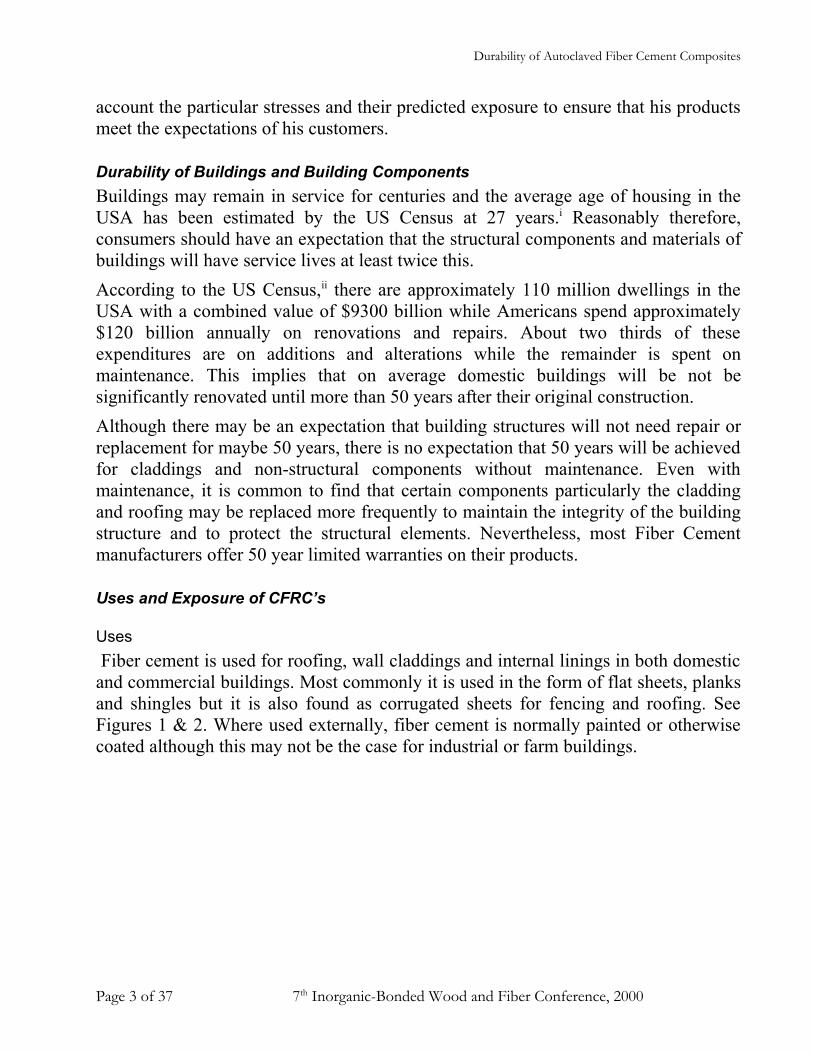
Uses Fiber cement is used for roofing, wall claddings and internal linings in both domestic and commercial buildings. Most commonly it is used in the form of flat sheets, planks and shingles but it is also found as corrugated sheets for fencing and roofing. See Figures 1 & 2. Where used externally, fiber cement is normally painted or otherwise coated although this may not be the case for industrial or farm buildings.
Page 3 of 37 7th Inorganic-Bonded Wood and Fiber Conference, 2000

Durability of Autoclaved Fiber Cement Composites
Figure 1: Fiber Cement Wall sidings
Fiber cement is immune to damage by water (unlike gypsum based lining boards) and this makes it particularly suitable for use behind tiling in wet areas. Fiber cement therefore, finds considerable use as backer boards for counter tops or wet area internal lining boards and these are usually covered and protected.
Figure 2: Fiber cement backer board for tiling
Corrugated fiber cement for roofing and fencing is usually not painted and is fully exposed to the normal environment. To the author’s knowledge, there has been relatively little usage of corrugated CFRC for roofing and none has been used for fencing in the USA although it is common in other parts of the world. This paper will be confined to the evaluation of the durability of CFRC’s in the most common uses in the USA - external wall claddings and internal lining boards. Some comment will also be made concerning the durability of Hatschek made fiber cement roofing. It will be seen that the performance of fiber cement in these environments can be extrapolated to its use in other situations.
Page 4 of 37 7th Inorganic-Bonded Wood and Fiber Conference, 2000

Durability of Autoclaved Fiber Cement Composites
ExposureThe exposure of CFRC’s therefore depends on the application. CFRC’s used as wall claddings will be subject to considerable changes in humidity and temperature as the surrounding air changes. In summer time CFRC may be exposed to direct sunlight and temperatures exceeding 120°F while in winter it may experience temperatures below freezing. There will be corresponding changes in the humidity.The result of both temperature and humidity changes is to cause the CFRC to change dimension. It will expand with increase in temperature or humidity and shrink with their decrease. Cyclic movements induced by these changes, result in cyclic stressing of the CFRC in normal service. It may also be subjected to mechanical stresses due to movement of the building structure from the influence of temperature, wind or earthquake.Externally exposed CFRC is also exposed to aggressive chemicals in the environment such as acid pollutants from power station emissions, naturally occurring CO2 etc. Generally, it will be most affected by acidic agents.Internally exposed CFRC is usually more protected from changes in temperature and humidity but may be subject to continuous wetting and attacks from aggressive cleaning agents such as soaps, wetting agents and detergents. It may also be subject to mechanical stresses induced by movement of the building structure.
Structure and Properties of Fiber Cement
Introduction The response of fiber cement to environmental stresses is dependent on its structure and properties. In this section, we will briefly consider the structure and the properties of fiber cement as it relates to its durability.
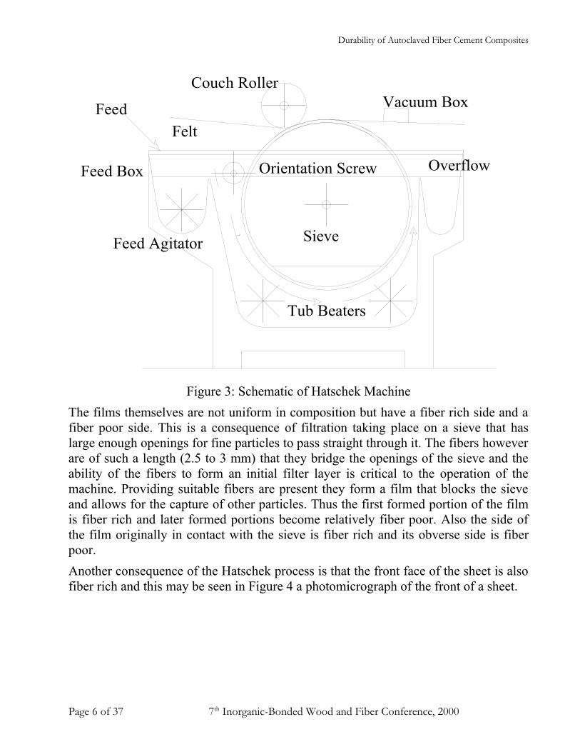
Structure of Fiber CementCFRC does not have an homogenous structure and this is a result of the manner of its formation on the Hatschek machine (Figure 3) by filtration of a dilute slurry of fibers and equidimensional sand and cement particles. This filtration process produces a film that is typically around 0.25 to 0.40 mm thick and each fiber cement sheet comprises a stack of these films. Thus, an 8 mm (5/16”) thick sheet will consist of between 20 to 30 or more thin films.
Page 5 of 37 7th Inorganic-Bonded Wood and Fiber Conference, 2000
Durability of Autoclaved Fiber Cement Composites
Couch Roller
Overflow
Sieve
Vacuum Box
Felt
Tub Beaters
Feed Agitator
Orientation ScrewFeed Box
Feed
Figure 3: Schematic of Hatschek MachineThe films themselves are not uniform in composition but have a fiber rich side and a fiber poor side. This is a consequence of filtration taking place on a sieve that has large enough openings for fine particles to pass straight through it. The fibers however are of such a length (2.5 to 3 mm) that they bridge the openings of the sieve and the ability of the fibers to form an initial filter layer is critical to the operation of the machine. Providing suitable fibers are present they form a film that blocks the sieve and allows for the capture of other particles. Thus the first formed portion of the film is fiber rich and later formed portions become relatively fiber poor. Also the side of the film originally in contact with the sieve is fiber rich and its obverse side is fiber poor. Another consequence of the Hatschek process is that the front face of the sheet is also fiber rich and this may be seen in Figure 4 a photomicrograph of the front of a sheet.
Page 6 of 37 7th Inorganic-Bonded Wood and Fiber Conference, 2000

Durability of Autoclaved Fiber Cement Composites
Figure 4 Surface of Hatschek Made Fiber CementIt will be seen that the fiber rich portion of each film is brought into contact with the fiber poor portion of the adjacent film and because of this, the bond between films is relatively weak. The film-on-film structure of the sheet also means that Hatschek made fiber cement is much more permeable parallel to the plane of the sheet than perpendicular to the plane. One consequence of this structure is that fiber cement is susceptible to penetration by aggressive agents along its exposed edges.Ideally, we would like a sheet material to have uniform properties in its planar dimensions. However, because of hydrodynamic action during the deposition of the films, the Hatschek machine tends to align the fibers in the machine direction. Consequently, the sheet is naturally stronger in the machine direction than in the cross direction. Most Hatschek machines have fiber orientation devices to help compensate for this deficiency. However, these are rarely fully effective in creating a uniformly planar distribution of properties and most real life CFRC will have noticeably different machine and cross direction strengths. This also has consequences for the performance and the durability of the fiber cement. Stacking or wrapping of 20 to 30 films to form one sheet as single films would be very slow and most Hatschek machines have more than one vat so that a stack of 3 to 6 films is wrapped simultaneously. In these circumstances, the fiber orientation devices are set to orient the fibers to the opposite direction in each successive vat that ensures that the finished sheet is plied and its properties are symmetrical if not uniform in all directions. An idealized structure for successive plies or layers in the finished product is illustrated below in Figure 6. Figure 5 shows a typical Hatschek Machine.
Page 7 of 37 7th Inorganic-Bonded Wood and Fiber Conference, 2000

Durability of Autoclaved Fiber Cement Composites
Figure 5: 4 Vat Hatschek Machine
MachineDirection
Ply 1 Fiber Direction
Ply 2 Fiber Direction
Figure 6: Fiber Orientation in Adjoining Layers of Fiber Cement.
Page 8 of 37 7th Inorganic-Bonded Wood and Fiber Conference, 2000

Durability of Autoclaved Fiber Cement Composites
Composition of Fiber CementMost fiber cement sold in North America is autoclaved as this composition is economical and performs well in North American climates. Autoclaving has the further advantage that the product may be cured and ready for shipping within 48 hours of manufacture as opposed to an air-cured product that may need the traditional 28 days of curing before use. Autoclaving however, results in a crystal structure in the hydrated cement products that is different from that produced at low temperatures. This structure is more susceptible to chemical attack by atmospheric CO2 and it responds differently to this attack than the air-cured product.
Mechanical Properties of Fiber CementThe mechanical properties of fiber cement depend on its composition and the orientation of the fibers in the sheet. Fiber orientation depends on the operating conditions within the sheet machine during sheet formation. Thus, the relative strengths and strains to failure in the machine and cross machine directions are determined by multiple factors. Strengths - Before cracking of the matrix the stress carried by the sheet in each direction is carried by both the matrix and the fibers. The relative amount of stress that is carried by each depends on the relative elastic moduli of the matrix and the fibers, the orientation of the fibers and the proportion of eachiii. Because practical CFRC’s contain more than the critical volume ivfraction of fiber, we may assume that after cracking the matrix does not carry any load and that the entire tensile or flexural load is carried by the fiber. We can also assume that fibers in alternate films are parallel to each other and lying at the same but numerically opposite angles to the machine direction. Under these assumptions, the ultimate directional flexural or tensile strengths may be predicted by expressions of the following type.
Page 9 of 37 7th Inorganic-Bonded Wood and Fiber Conference, 2000

Durability of Autoclaved Fiber Cement Composites
directionmachineandfibrebetweenangleaveragedirectioncrossXD
directionmachineMDlengthfibercritical
diameterfiberdlengthfiber
matrixtofibersofstrengthbondfibreoffractionvolumev
fibertheofstrengthcompositetheofstrength
whered
v
v
dv
v
c
f
FU
CU
ccf
cfufCUXD
ccf
cfufCUMD
===
==
==
===
⋅−⋅⋅⋅⋅=
⋅−⋅⋅=
⋅−⋅⋅⋅⋅=
⋅−⋅⋅=
θ
τ
σσ
θτ
θσσ
θτ
θσσ
sin)2(
sin)1(
cos)2(
cos)1(
We can use these expressions to estimate the average angle between the fibers and the machine direction from the ratio of the measured strengths in the orthogonal directions. If we define the cross-ratio as the ratio of the strength in the cross direction to the strength in the machine direction, then the average angle of the fibers (2) is given by
)1(tan 1XR
−=θ
The orientation of the fibers does not change once the sheet has been formed on the Hatschek Machine and it is reasonable to assume that the length of the fibers does not change (although their properties may change with time). Therefore, any changes in the measured strengths, reflect changes in the bond between the fibers and the matrix or changes in the fiber properties. We can therefore use the changes in mechanical strengths to evaluate the effects of weathering. Strains - The strain at various parts of the stress/strain curve is also observed to change with time. If the bond strength of the fibers to the matrix is insufficient to break the fibers, then the fibers will pull out during fracture. The proportion of fibers that pull out or break will vary with their location and orientation relative to a crack in the matrix. The stress in the fiber at pullout is given by the following general expression.
Page 10 of 37 7th Inorganic-Bonded Wood and Fiber Conference, 2000
Durability of Autoclaved Fiber Cement Composites
.
..
fibertheofdiameterdandfibertheoflengthl
matrixtofiberofstrengthbondfibertheofnorientatiotorelatedfactorefficiency
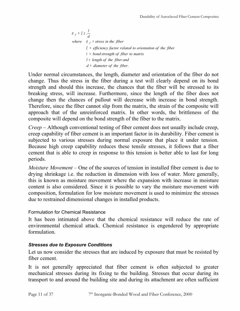
fibertheinstresswheredl
f
f
====
=
=
τξ
σ
τξσ
Under normal circumstances, the length, diameter and orientation of the fiber do not change. Thus the stress in the fiber during a test will clearly depend on its bond strength and should this increase, the chances that the fiber will be stressed to its breaking stress, will increase. Furthermore, since the length of the fiber does not change then the chances of pullout will decrease with increase in bond strength. Therefore, since the fiber cannot slip from the matrix, the strain of the composite will approach that of the unreinforced matrix. In other words, the brittleness of the composite will depend on the bond strength of the fiber to the matrix.Creep – Although conventional testing of fiber cement does not usually include creep, creep capability of fiber cement is an important factor in its durability. Fiber cement is subjected to various stresses during normal exposure that place it under tension. Because high creep capability reduces these tensile stresses, it follows that a fiber cement that is able to creep in response to this tension is better able to last for long periods. Moisture Movement – One of the sources of tension in installed fiber cement is due to drying shrinkage i.e. the reduction in dimension with loss of water. More generally, this is known as moisture movement where the expansion with increase in moisture content is also considered. Since it is possible to vary the moisture movement with composition, formulation for low moisture movement is used to minimize the stresses due to restrained dimensional changes in installed products.
Formulation for Chemical ResistanceIt has been intimated above that the chemical resistance will reduce the rate of environmental chemical attack. Chemical resistance is engendered by appropriate formulation.
Stresses due to Exposure ConditionsLet us now consider the stresses that are induced by exposure that must be resisted by fiber cement. It is not generally appreciated that fiber cement is often subjected to greater mechanical stresses during its fixing to the building. Stresses that occur during its transport to and around the building site and during its attachment are often sufficient
Page 11 of 37 7th Inorganic-Bonded Wood and Fiber Conference, 2000

Durability of Autoclaved Fiber Cement Composites
to cause its immediate failure. For example, attempting to pick up a fiber cement plank perpendicular to the sheet in the center of its length, may cause it to fracture if it is picked up too rapidly or if it has become saturated. Either circumstance may cause breakage of the plank because its self-weight or its self-weight combined with inertial forces exceed it current strength. However, assuming the fiber cement survives intact and is fixed to the building, it then becomes subject to other stresses. Examples of the stresses are
a) Repetitive Mechanical Stresses – such as i) Direct stresses due attachment to the building structure from forces such as
wind, earthquake, building vibration. ii) Restrained expansion and contraction due to thermal cycling. iii)Restrained expansion and contraction due to wet/dry cycling.
Repetitive mechanical stresses may have directly observable effects such as loosening of the fixings or cracking of the sheet. They may have more subtle effects such as delamination.
b) Assisted Mechanical In this case, another agent such as freezing and thawing water induces mechanical stresses that may damage the fiber cement.
c) Chemical Exposure - such asi) carbonation of matrixii) oxidation of the fibersiii)depolymerization of the celluloseiv) biological attack of the cellulose
The stresses induced by chemical exposure may range from the chemical dissolution of the matrix to the enhancement of the mechanical stresses of fixed product due to increased moisture movement.
Case Studies of Weathering Processes in Fiber CementWeathering in fiber cement follows the pattern of other fiber reinforced materials. The rate of change in the product is dependent on the particular exposure conditions and is faster for unprotected materials than for materials that are painted or otherwise finished.
Case I: Unprotected Fiber Cement in a harsh Tropical Environment Let us first consider fiber cement that has been exposed unprotected to direct weather in a harsh tropical environment. It is convenient to divide the observations into stages
Page 12 of 37 7th Inorganic-Bonded Wood and Fiber Conference, 2000

Durability of Autoclaved Fiber Cement Composites
although the weathering process is one of continuous change. The changes are as follows.Stage 1)Loss of ductility usually with improvement of strength and resulting from
i) Improved matrix/fiber bond due to carbonation of the matrix.ii) Improved matrix/fiber bonds due drying and shrinkage.iii) Increased interlaminar bond due to carbonation.
This loss of ductility in most cases will be accompanied by a small increase (approximately 10% or less) in the flexural or tensile strength. The loss of ductility is observed after exposures of only a few months and is due mainly to improved matrix/fiber bond following carbonation. Loss of ductility will continue at reducing rate for the life of the product but the strength of the product does not continue to rise and has reached its peak sometime before 12 months. After some further exposure usually about 2 years it will be found that the fiber cement has lost the early gains in strength even to the point where it is below its strength at manufacture.
Stage 2)Loss of Mechanical properties resulting from i) Reduced interlaminar bond and partial delamination of the fiber cement.ii) Disruption of the matrix.iii)Debonding of the fibers and the matrix.
The loss of mechanical properties observed at 2 years exposure is most likely due to delamination of the structure. This is the result of two competing forces. Carbonation of the matrix tends to increase the interlaminar bond and the flexural strength of the sheet because the sheet acts more as an integrated sheet than a “stack of cards”. Conversely, thermal and hygral stresses tend to disrupt the interlaminar bond and reduce the flexural strength. Less effect is observed on the tensile strength because stress is carried directly in the fibers and is not so dependent on the transfer of load from lamination to lamination. Continued exposure to the thermal and hygral cycling has the effect of disrupting the matrix as well as the bonds between laminates. The fibers will also debond as a high proportion of the fiber is at the interface between laminates. Thus the strength will continue to deteriorate and after 3 or so years in this exposure may be as low as 60% of the strength at manufacture. Carbonation also increases the moisture movement of the matrix and this increases the magnitude of the thermal and hygral stresses resulting in accelerated deterioration of mechanical properties.It is also observed that the cellulose has reduced degree of polymerization (DP). This indicates that it has been attacked by oxygen from the air or by
Page 13 of 37 7th Inorganic-Bonded Wood and Fiber Conference, 2000

Durability of Autoclaved Fiber Cement Composites
microorganisms such as molds or bacteria. It should be noted however, that cellulose which has an initial DP after autoclaving of about 1200 to 1500 has to be degraded to DP below 900 or so before the strength of the composite is reduced. This is because the determining factor in the composite strength is the balance between pullout load and fiber strength. It the pullout load does not exceed the fiber strength the fibers are not stressed to breaking thus the composite strength is not affected until a significant loss of fiber strength has occurred. This is found practically at DP’s less than 900.
Stage 3)Serious loss of Mechanical Properties caused byi) Depolymerization of the cellulose.ii) Oxidation of the celluloseiii)Debonding of the fibers from the matrix – usually due to deterioration of the
matrix by attack from weathering products from the fibers.iv) Further carbonation of the matrix with its increased moisture movement.
After some 5 years in this exposure, the sheet usually shows extreme deterioration to the point where there may be loss of strength to less than 30% of the manufactured strength. This is accompanied by further deterioration of the cellulose whose DP may be as low as 600 and it can be concluded that the deterioration of the fiber has now become significant. Depolymerization of the fibers may be the result of oxidation or biological attack. In either case there is a possibility of the formation of acidic products and these materials will dissolve the matrix. This clearly leads to a reduction in the fiber matrix bond that coupled with a loss in fiber strength exhibits itself in the loss of strength of the CFRC. The breakdown of the matrix is most pronounced on the surface and it may be possible to manually rub away the surface with finger pressure. Surface deterioration is often accompanied by visible mold growth and obvious softness of the surface.Carbonation of the matrix will be almost complete by this stage and the moisture movement of the sheet will have significantly increased. Thus, the movement cycles that the sheet exhibits with changes in moisture content are greatly increased resulting in more stress due to moisture content differences between the interior and the exterior of the sheet. Thus, the sheet tends to break down more quickly.With further exposure the sheet will eventually completely fail and it seems likely that unprotected exposure to this severe tropical environment will result in the complete failure of the sheets in about 10 years or so.
Page 14 of 37 7th Inorganic-Bonded Wood and Fiber Conference, 2000

Durability of Autoclaved Fiber Cement Composites
Case II: Fiber Cement installed on Frame and PaintedLet us now consider a more normal situation where the fiber cement is installed on a timber or metal frame and is painted to protect it. In this situation the sheet is still exposed to externally imposed stresses but they are much less severe. As mentioned earlier the sheet is likely to be exposed to greater mechanical stresses during its transport and installation on the building than the stresses to which it will be subjected during service. We can also divide the weathering into three stages although as before the stages are merely a convenient way of dividing the process into more manageable bites.Stage 1)Loss of ductility usually with improvement of strength and resulting from
i) Improved matrix/fiber bond due to carbonation of the matrix.ii) Improved matrix/fiber bonds due drying and shrinkage.iii) Increased interlaminar bond due to carbonation.
Weathering at this level of exposure is almost indistinguishable from the severe case because of carbonation of the matrix. The rate of carbonation is determined more by the amount of CO2 in the atmosphere than other factors and proceeds at approximately the same rate as in more severe exposure. As before, this loss of ductility will be accompanied by a small increase (approximately 10% or less) in the flexural or tensile strength. The loss of ductility is observed after exposures of only a few months and is due mainly to improved matrix/fiber bond following carbonation. Loss of ductility will continue at a decreasing rate for the life of the product but the strength of the product does not continue to rise and has reached its peak sometime before 12 months. More prolonged exposure is required in this case (usually about 3-5 years or more) before it will be found that the fiber cement has lost the early gains in strength. Loss of strength to below its strength at manufacture may take up to 5 years.
Stage 2)Loss of Mechanical properties resulting from i) Reduced interlaminar bond and partial delamination of the fiber cement.ii) Disruption of the matrix.iii)Debonding of the fibers and the matrix.
The loss of mechanical properties observed at 3 to 5 years exposure is most likely due to partial delamination of the structure. Again, this is the result of two competing forces. Carbonation of the matrix tends to increase the interlaminar bond and the flexural strength of the sheet because the sheet acts more as an integrated sheet than a “stack of cards”. Conversely, thermal and hygral stresses tend to disrupt the interlaminar bond and reduce the flexural strength. Less effect is
Page 15 of 37 7th Inorganic-Bonded Wood and Fiber Conference, 2000

Durability of Autoclaved Fiber Cement Composites
observed on the tensile strength because stress is carried directly in the fibers and is not so dependent on the transfer of load from lamination to lamination. As in the previous case, continued exposure to the thermal and hygral cycling has the effect of disrupting the matrix as well as the bonds between laminates. However, the magnitude of the stresses is much less because of the protection offered by the surface coatings. These reduce the rate at which stresses can develop by reducing the rate of transfer of moisture to the environment and in some cases reducing the rate at which thermal changes can take place. Coatings also inhibit the ingress of CO2 and reduce the rate of carbonation. The effects of carbonation can thus be ameliorated as the rate at which stresses develop is lower and the sheet has time to creep and reduce them to tolerable levels. Nevertheless, it is observed that there will be a reduction in strength over the period of some 5 years. It seems likely that this is due to deterioration of the cellulose as cellulose removed from exposed sheet exhibits some reduction in DP. Since the cellulose has been largely protected from attack by microorganisms other means of deterioration must have occurred. Two mechanisms are possible.
1. Cellulose is susceptible to attack by alkalis and will depolymerize if exposed to wet alkalis. CRFC is normally alkaline when first produced and this could provide a source of alkali at least in the early stages of exposure. However, the alkalinity of the interior of the sheet rapidly diminishes with carbonation and this would seem to be self-limiting in about 3 to 5 years.
2. Cellulose is also subject to oxidation that may also be promoted by humidity and by alkalinity of the matrix.
In either case, the reduction in strength seems to be due to the deterioration of the cellulose.
Stage 3)Serious loss of Mechanical Properties caused byi) Depolymerization of the cellulose.ii) Oxidation of the celluloseiii)Debonding of the fibers from the matrix – usually due to deterioration of the
matrix by attack from weathering products from the fibers.iv) Further carbonation of the matrix with its increased moisture movement.
Practical CFRC has not reached this stage in climates similar to the Southern USA. At the time of writing painted autoclaved CFRC of the initial formulations has had almost 20 years satisfactory exposure in Australia with few signs of long-term deterioration. Naturally, there is a decrease in ductility of this material and this will continue to some limit state while the product is in use. The more modern
Page 16 of 37 7th Inorganic-Bonded Wood and Fiber Conference, 2000
Durability of Autoclaved Fiber Cement Composites
formulations with reduced moisture movement have had approximately 16 years exposure with no initial durability problems and continuing good performance.It should be noted however that even in these circumstances, carbonation of the matrix will be almost complete by about 5 years and the moisture movement of the sheet will have significantly increased. Therefore, although the movement cycles that the sheet exhibits with changes in moisture content are greatly increased, the sheet has still been able to withstand these stresses.
Case III: Installation internally as Backer board or LiningLet us now consider internal exposure where the fiber cement is installed as an internal lining or as a backer to coatings such as tile on a timber or metal frame. In this situation the externally imposed stresses are much less severe and the sheet is much more likely to be exposed to greater mechanical stresses during its transport and installation in the building than the stresses to which it will be subjected during service. During service, the sheet is protected from thermal and hygral stresses because it is inside the building structure and is also protected from extremes of temperature and humidity. Furthermore, if the sheet is tiled over or painted, the process of carbonation is inhibited due to reduced access of CO2 and moisture to the sheet. Access of oxygen to the cellulose is also limited reducing the possibility of its deterioration from this cause. All in all the processes of deterioration described above are inhibited and internal CFRC linings do not degrade rapidly. Indeed CFRC that was made in Norway during WWI (around 1917) was reported to be in good serviceable condition as late as 1963v. No details were given of the specific formulation of the CFRC, but it would seem that the modern formulations should be capable of at least this performance and will last at least as long.To the author’s knowledge, the only problems that have been associated with CFRC internal linings were due to incorrect fixing of the sheet under ceramic tiling. Ceramic tiling imposes bending stresses on CFRC due to the tendency of typical wall tiles to expand (they try to revert to the hydrated state of clay) while the sheet beneath tries to shrink. If the tile substrate is not properly fixed then the tiled surface may bow to the point that the structure will fracture. However, this is hardly a durability problem with CFRC and can be ignored in this discussion.
Case IV: Lap Siding Exposed to Freezing and ThawingMost of the CFRC that has been used in the USA has been exposed in the warmer parts of the country that are not subject to significant amounts of freezing and thawing. Recently there has been a penetration of parts of the country that are subject
Page 17 of 37 7th Inorganic-Bonded Wood and Fiber Conference, 2000

Durability of Autoclaved Fiber Cement Composites
to this weathering and it is appropriate to consider the effects of this exposure. Let us consider the case of a painted wall siding installed on a timber or metal frame. We will ignore the other weathering effects that have already been described above because they are essentially the same as Case II. Freeze thaw damage occurs because permeable materials absorb liquid water that expands when it freezes. On subsequent thawing, the material remains expanded due to expanded porosity and its permeability is increased. If it has access to more liquid water the pores become filled to a greater extent with water that expands the pores further on the next freezing. Repeated cycles of wet freezing and thawing will eventually cause the material to completely break down. Early signs of the problem in most materials are surface fretting but in fiber cement, a common sign will be visible delamination or cracking. We have deliberately emphasized the fact that freeze thaw damage requires access of liquid water to the material. The presence of water vapor alone will not cause freeze thaw damage because the pores of a hygroscopic material such as fiber cement cannot be filled with water absorbed from vapor in the air. At normal atmospheric humidity and temperature the equilibrium water content as a proportion of the oven dry weight is about 7% compared to about 35% required to fully saturate the same sheet. Thus, there is ample room in the pores of the sheet for the water to expand without damaging it.Let us now consider the mechanics of freeze thaw damage of fiber cement wall siding. The most susceptible part of the fiber cement is its edge that may be ten times more permeable than its face or back. Even so, fiber cement is extremely permeable from any direction and water will readily penetrate it. However, when it is painted, its permeability to liquid water is much reduced and while the coating remains intact, very little water will penetrate it. If the coating is not maintained however, the fiber cement will become susceptible to freeze thaw damage. It should be noted however, that most coatings will penetrate the surface to an extent and even when they are removed in bulk from the surface, sufficient will remain under the surface to block many of the pores and provide some protection.It seems to the author however, that the most vulnerable portion of a siding component is the edge of the sheet that has been installed close to the ground where there is a possibility of snow lying against it. See Figure 7
Page 18 of 37 7th Inorganic-Bonded Wood and Fiber Conference, 2000

Durability of Autoclaved Fiber Cement Composites
Point of VulnerabilityFooting
Soil
Snow againstSiding
Figure 7: Snow drifted against a lap siding.At this position, the edge of the sheet is exposed to liquid water whenever the snow melts and penetration of water into the sheet is a real possibility. Furthermore although the sheet may be painted, full cover of the edge with paint cannot be guaranteed and the coating is likely to be thin at this point. Thus, there is a chance of freeze thaw damage at this place.Let us now consider the actual vulnerability of fiber cement to freeze thaw damage. We have included in graphical form the effects of freeze thaw on the Modulus of Elasticity of fiber cement. See Figure 8. The testing was conducted as follows.
1. Duplicate specimens 12” by 6” specimens were cut for both machine direction and cross direction ASTM flexural test and saturated in water.
2. After saturation, one set of each direction tests was placed in a close fitting zip lock bag with an additional 10% by weight of water over the weight of the specimen. Thus, there was free water contained in the bag.
3. The specimens were then subjected to 50 cycles of freezing to -20°C followed by thawing to +20°C.
Page 19 of 37 7th Inorganic-Bonded Wood and Fiber Conference, 2000

Durability of Autoclaved Fiber Cement Composites
4. After the first 50 cycles of freezing and thawing, the control sample specimens were tested to destruction in the ASTM 1185 flexural test. The remaining samples were then loaded to 40% of the average maximum load of the control samples, without removing them from their zip-lock bags. Their modulus of elasticity was used to evaluate any changes in their properties.
5. The test specimens were subjected to a further 50 cycles of freezing and thawing and their flexural modulus of elasticity was determined as described in 4. Some of the specimens broke during the testing and the maximum load to which the remaining specimens were subjected was therefore reduced to avoid further breakage.
6. The specimens were then returned for a further 50 cycles of freezing and thawing.
7. After 150 cycles of freezing and thawing it was found that no specimens could withstand the determined maximum load (40% of the original undamaged strength) and all of them were broken. Therefore, the test was terminated.
MoE vs Cycles of Freezing and Thawing
0
200400
600
8001000
1200
0 50 100 150
No of Cycles of Freezing Thawing
MoE
ksi MoE Perp
MoE Par.
Figure 8: Response the Modulus of Elasticity of fiber cement to cycles of freezing and thawing.
The test was set up to simulate the conditions that may exist in the real world where typically a material will not be saturated at each cycle and neither will it be dry internally. It will be seen that the specimens tend to a limiting condition after about 100 cycles. Admittedly, the specimens are considerably weakened but they remained
Page 20 of 37 7th Inorganic-Bonded Wood and Fiber Conference, 2000

Durability of Autoclaved Fiber Cement Composites
intact and showed only limited signs of delamination. The results of the tests show that the specimens can be subjected to reasonable freeze thaw when there is access to liquid water with low damage. Tests where dry specimens are exposed cycles of freezing and thawing show essentially no damage from this treatment. Combining these results indicates that protected lap siding can be exposed to the worst freeze thaw conditions in the USA with little likelihood of freeze thaw damage. This is dependent on the maintenance of protective coatings to some extent but also relies on the fact that the fiber cement is installed in favorable conditions and has moderate freeze thaw resistance.
Case V: Roofing ExposuresLet us now consider the situation of fiber cement roofing however, the discussion will be confined to Hatschek made roofing and not the filter press type. These types of materials behave differently because of their pore structure and their overall permeability.Firstly, let us consider the environment on the roof. This is the most extreme environment for exposure and approaches the situation of unprotected sheets in a tropical environment described in Case I. Indeed in some ways a coated but restrained sheet on a roof is subject to more severe conditions than Case I and may show more rapid deterioration. The roof is subject to direct sunlight, wetting and hail, ice or snow in some places. Thus, the roof cladding is subject to high and low temperatures whose rate of change may be quite rapid. The roof is also directly subjected to strong wind forces that may strain the fixings for its surface. Roofs are also subject to mechanical damage due to hail and rain. The exposure of the roof gives easier access to CO2, O2 and airborne pollutants that are not experienced so severely by other parts of the building. Finally, the typical shingle installation of between 2 and 3 layers traps water between the layers. This increases the chances of the individual pieces of fiber cement becoming saturated with water and experiencing freeze thaw damage. This damage is accelerated by the fact that free water is often trapped between the shingles by capillary action and this can diffuse into the shingles during the thaw part of the cycle. This is exacerbated by the fact that the roof does not drain as quickly as a vertical structure and free water tends to remain on the roof.The author has direct experience of three installations where fiber cement shingle roofing was used. One of these was in a snow area, another was in a warm wetter climate similar to coastal Southern USA and the other was in a warm dry climate similar to the inland Southern USA. The first and the third installations used sheet
Page 21 of 37 7th Inorganic-Bonded Wood and Fiber Conference, 2000

Durability of Autoclaved Fiber Cement Composites
shingles approximately 4’ by 2’ cut with a multinotch tab so that the tabs protruded to form the exposed roof. The second installation used single shingles.The installation in the snow area was installed on a large hotel whose entire loft was an entertainment area and bar. The roof had dormer windows at about 30’ intervals along its length and it was found that the heat from these dormers melted the snow around them. Despite their being painted, these shingles failed within 1 winter season by delamination from freeze thaw damage. It is estimated that they were probably subjected to between 1 and 2 freeze thaw cycles per day. In some cases, this may have been more than that due to the habit of the patrons of the hotel to open and close the dormer windows. Since the problem became evident during the first winter season, replacement shingles were supplied for the affected areas that had been coated with clear acrylic coating. However, these also failed not long after their installation. The problem was eventually solved by replacing the shingles with fully compressed shingles that had been completely coated on all sides with a clear acrylic coating. The third installation was over a large swimming pool complex and this tended to keep the underside of the shingles moist. The climate of the area is also dry and hot in the summer time so that the shingles were kept dry on the top and moist underneath. These shingles showed signs of severe distress within 18 months of their installation. The ends of the shingles curled and many of them tore out their fixings. Some of the tabs actually broke off and came off the roof. Shingles that were removed intact, showed cracking in the head of the notch that often progressed up the shingle. Vertical cracking also appeared to be a precursor of cracking across the shingle and these cracks resulted in the loss of the protruding tab. The problem was resolved by replacing the damaged shingles with a revised design where the notch between tabs was radiused rather being square cut. However, it was clear that the failure had resulted from a combination of factors and while the revised notch design helped, it did not resolve the problem entirely. Eventually, a decision was made to quit this type of shingle because of its inherent deficiencies. Figure 9 illustrates.
Page 22 of 37 7th Inorganic-Bonded Wood and Fiber Conference, 2000

Durability of Autoclaved Fiber Cement Composites
Multinotch ShingleLayout
Cracking developed here
Figure 9: Multinotch Fiber Cement ShingleThe second installation comprised single shingles i.e. similar to traditional wood shingles installed in a warm coastal climate. These shingles have performed well with limited distress evident after some 7 to 8 years of exposure. Controlling factors in their success appear to be their small size and their installation in a wetter climate where they are less subject to violent weather changes. Nevertheless they are showing some curling and loosening around their fixings. Once they have curled, they are very likely to be damaged by maintenance work on the roof as they tend to set in the curled condition.The author also has had reported to him some experience with other installations. An experimental installation of shingles on a roof in the mountainous part of the USA showed rapid failure due to freeze thaw damage that resulted in them being replaced after only one winter season. Failure occurred in the valleys of the roof where water accumulates more rapidly and is more likely to remain in the cladding. The author has some limited anecdotal evidence of the performance of European shingles and artificial slates. Air cured shingles that are usually heavily compressed, are widely used in Europe. These perform well in the European environment where conditions tend to be cool and wet, however, they have not performed as well in hotter drier climates in Australia. It appears that this is due to their inherently higher moisture movement which is of less significance where there is less drying. The author has seen shingles that have cracked before installation while still in their
Page 23 of 37 7th Inorganic-Bonded Wood and Fiber Conference, 2000

Durability of Autoclaved Fiber Cement Composites
packaging and this is due to them drying out on their edges when they are wet in the interiors.
Summary of the LiteratureA synopsis of the literature on fiber cement aging is reported in Appendix B and it will be seen that there are no reports on naturally aged composites beyond 5 years. However, there is consensus by most authors on several items.1. Except for an increase in moisture movement, there is little change in the
mechanical properties of autoclaved composites exposed to natural weathering for 5 years.
2. The most effective accelerated weathering regimes includes wet-dry cycles mixed with accelerated carbonation of the composite.
3. Dry freeze-thaw cycling induces little change in the composite mechanical properties.
4. The major effects of aging are due to the increase in interfacial bond of the fibers to the matrix.
Rules of thumb for Durable Fiber CementDurable fiber cement is a combination of properly manufactured material with the appropriate formulation for the anticipated exposure combined with correct installation and maintenance. It is clear from the above that there will be many circumstances where fiber cement may not endure for 50 years. For example, it is unreasonable to expect properly proportioned fiber cement to endure 50 years unprotected against a harsh tropical environment. Similarly, it is anticipated that less than fully compressed fiber cement roof shingles may fail in a severe freeze thaw environment. However, fiber cement has performed well in many conditions provided it has been formulated for the exposure. The following represents practical experience that ensures that durable fiber cement can be obtained. The discussion should be seen in context of the comments on durability testing in the Appendix A to this paper. The specific properties that are required depend on the circumstances that fiber cement faces and are dependent on the stage in the life of the product.
Up to and including installationStrength: Fiber cement needs to have a minimum strength so that it can be handled without breaking. It is usually recommended that fiber cement be kept dry, but it is unrealistic to assume that this will always happen. . It has been found that a practical
Page 24 of 37 7th Inorganic-Bonded Wood and Fiber Conference, 2000
Durability of Autoclaved Fiber Cement Composites
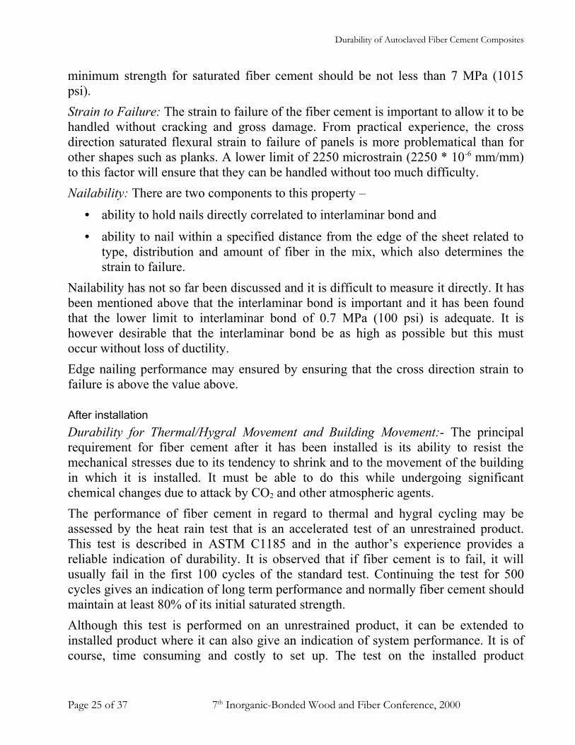
minimum strength for saturated fiber cement should be not less than 7 MPa (1015 psi). Strain to Failure: The strain to failure of the fiber cement is important to allow it to be handled without cracking and gross damage. From practical experience, the cross direction saturated flexural strain to failure of panels is more problematical than for other shapes such as planks. A lower limit of 2250 microstrain (2250 * 10-6 mm/mm) to this factor will ensure that they can be handled without too much difficulty.Nailability: There are two components to this property –
• ability to hold nails directly correlated to interlaminar bond and
• ability to nail within a specified distance from the edge of the sheet related to type, distribution and amount of fiber in the mix, which also determines the strain to failure.
Nailability has not so far been discussed and it is difficult to measure it directly. It has been mentioned above that the interlaminar bond is important and it has been found that the lower limit to interlaminar bond of 0.7 MPa (100 psi) is adequate. It is however desirable that the interlaminar bond be as high as possible but this must occur without loss of ductility.Edge nailing performance may ensured by ensuring that the cross direction strain to failure is above the value above.
After installationDurability for Thermal/Hygral Movement and Building Movement:- The principal requirement for fiber cement after it has been installed is its ability to resist the mechanical stresses due to its tendency to shrink and to the movement of the building in which it is installed. It must be able to do this while undergoing significant chemical changes due to attack by CO2 and other atmospheric agents.The performance of fiber cement in regard to thermal and hygral cycling may be assessed by the heat rain test that is an accelerated test of an unrestrained product. This test is described in ASTM C1185 and in the author’s experience provides a reliable indication of durability. It is observed that if fiber cement is to fail, it will usually fail in the first 100 cycles of the standard test. Continuing the test for 500 cycles gives an indication of long term performance and normally fiber cement should maintain at least 80% of its initial saturated strength.Although this test is performed on an unrestrained product, it can be extended to installed product where it can also give an indication of system performance. It is of course, time consuming and costly to set up. The test on the installed product
Page 25 of 37 7th Inorganic-Bonded Wood and Fiber Conference, 2000

Durability of Autoclaved Fiber Cement Composites
implicitly includes a component of creep but without giving specific information on its magnitude. It is therefore difficult to extrapolate the results of individual tests to different installation conditions.It has also been found that product whose creep is high will perform well in the heat rain test and in service, when its initial tensile strain to failure exceeds 30% of its oven dry to saturated moisture movement. This can be used as an indication of likely good performance. Durability for Freeze-thaw Exposure:- It is clear that the greatest increase in freeze thaw performance can be achieved simply by sealing external pores of the fiber cement to access from water and this is exactly the same mechanism that applies with other materials having a continuous pore system. However, freeze-thaw performance in the field is affected by the specific exposure conditions particularly whether liquid water lies in prolonged contact with the material so that it can absorb liquid. The amount of water that is absorbed depends on the permeability of the surface and time of contact. For vertical wall sidings, two factors seem to improve the durability against freeze-thaw damage, water does not pool on the surface of the wall and wall sidings are normally painted. However, water can pool on the ground next to the footings, so it is necessary to ensure that the lowest piece of lap is not installed in contact with the ground. It is also necessary to ensure that the entire wall is adequately painted particularly the exposed sheet edges. Roofing shingles suffer a much more severe exposure primarily because a shingle roof tends to trap water between the layers of shingles and along roof valleys. Furthermore, the roof tends to suffer more frequent freeze-thaw cycles than it surroundings, due to the activities of the occupants of the building. The roof also offers much more severe heat, light and UV exposure to paints and coatings which tend to weather and deteriorate more rapidly than in other situations. Therefore, it may be prudent to do more than seal the surface of the shingles and it has been found that fully compressed shingles are required for good performance in these circumstances. The freeze-thaw test described above shows that essentially no change occurs up to 50 cycles and that no more than 50% loss of property will occur after 75 cycles. This seems to be adequate for painted wall sidings and better protected materials. In the same test, a fully compressed product will show few changes up to 250 or more cycles. This is a consequence of the improvements in interlaminar bond that is brought about by compressing the board and the reduction in void space.
Page 26 of 37 7th Inorganic-Bonded Wood and Fiber Conference, 2000
Durability of Autoclaved Fiber Cement Composites
InstallationFixing:- It is important that the most appropriate fixing be used. Fiber cement needs flexible fixing that allows it to move relative to the building structure. The early versions of CFRC were not able to creep and fixing them on rigid frames with rigid couplings was one of the factors that caused their failure. Fixing fiber cement to wooden frames usually causes no problems because the wooden frames move in the same way as the fiber cement. Thus if the fiber cement is dried out and shrinks then the wood behaves in the same way. However, the same fiber cement fixed to a steel frame with rigid fixings is likely to fail because the steel frame will expand when heated and the fiber cement will expand when heated but simultaneously shrink through being dried out. Flexible couplings are required in these circumstances to avoid the cracking of the fiber cement.Coating of externally exposed Fiber Cement:- Despite the fact that unprotected CFRC is commonly used with good results in farm and industrial buildings in Europe and elsewhere, prudent practice and experience tells us that painting is a good way to improve CFRC durability. The benefits of painting are gained primarily from protection against penetration of water into the CFRC and coincidentally the building and this gives the following benefits.
1. Reduction in the rate at which carbonation of the matrix takes place.2. Protection of the cellulose from biological attack particularly on the surface.3. Protection against attack by other chemical agents such as acid rain (this is not
a big issue in most areas but could be in heavily polluted regions.)4. Protection against freeze thaw damage.
Maintenance:- As with other materials CFRC benefits from regular maintenance although this is less critical than for other materials because of its inherent durability.
Conclusions1. The performance of CFRC in climates similar to the southern USA has been
demonstrated to be good and this material has proved satisfactory for periods of more than 18 years. Where used in a protected internal environment similar materials performed satisfactorily for periods of more than 40 years. In both cases however, it has proved important that the CFRC be installed in an appropriate manner and subsequently maintained correctly.
2. There is no doubt that CFRC can be made to break down in severe conditions. The effects of weathering may range from the mechanical breakdown of freeze-thaw damage to complete destruction of the material due to chemical or biological attack.
Page 27 of 37 7th Inorganic-Bonded Wood and Fiber Conference, 2000

Durability of Autoclaved Fiber Cement Composites
3. There is also no doubt that inappropriate installation may lead to failure and it is important CFRC be installed with flexible fixings that allow its movement relative to the building structure. It is also beneficial for CFRC’s to be painted or coated to protect them although CFRC has high inherent durability. Painting will certainly extend the life of CFRC in external exposures principally by prevention of ingress of water that acts as a catalyst to many reactions involving agents aggressive to CFRC.
4. Experience with CFRC and other materials also tells us that it is appropriate to maintain them to ensure their long-term performance. However, CFRC has less need for maintenance than other materials because if its high inherent durability.
5. It is the author’s conclusion that 50 years durability for CFRC is a reasonable expectation providing that it is selected, installed and maintained in a manner appropriate for its anticipated exposure.
Page 28 of 37 7th Inorganic-Bonded Wood and Fiber Conference, 2000

Durability of Autoclaved Fiber Cement Composites
Appendix A: Testing Durability
IntroductionA practical problem that arises in all long-term tests is the testing of durability. A paradox soon becomes apparent that it is necessary to know something of the performance of the material under test to design an appropriate test regime and to interpret the results. Clearly, the durability performance is not known in advance and thus the testing of durability develops into an iterative process that tends to change as the more important weathering processes become better understood. Furthermore, it is possible to introduce effects that occur because of the acceleration regime that do not appear in real time weathering. Some caution therefore has to be taken in the calibration of the test methods. In general however, the testing should
a) Reflect the properties and behavior of fiber cement.b) Accelerate the deterioration of the fiber cement in a predictable way that is
scaleable to real time. c) Reflect the exposure conditions.d) Reflect anticipated installation practices. e) Be quantitative and objective.f) Reflect real time long-term changes that take place in product without
introducing effects related to the acceleration regime.Two different types of test are usual.
a. Product or Materials where the inherent material properties are under investigation and the results of tests will be used to compare different materials or to generate recommendations for the use of the material under test.
b. System where the material is tested to simulate exposure in a way that is similar to its anticipated use.
Test MethodsNumerous test methods have been devised for evaluating material durability that can be divided into real time and accelerated methods. Test methods can usually be applied to either product or systems containing the product, however, it is clearly less time consuming to apply them to the product because of the reduction in the number of tests that will be required. Clearly, the external exposure of fiber cement will give the most reliable indication of its long-term durability because the conditions are closest to its normal exposure. It is usual to expose samples in racks to direct atmosphere without protection. The effects of various parameters such as direct sunlight and heat may be made stronger by
Page 29 of 37 7th Inorganic-Bonded Wood and Fiber Conference, 2000

Durability of Autoclaved Fiber Cement Composites
exposing specimens at the latitude angle facing south in the Northern Hemisphere. It is also possible to increase the effects of sunlight and heat by the use of mirror concentrators. Other atmospheric conditions such as rain may be made more intense with the addition of water sprays.* Tests of the properties of the materials are made by withdrawing samples at different intervals. In the case of fiber cement these will be the usual strength tests and may include evaluation of the degree of carbonation, change in cellulose content, DP of Cellulose, moisture movement etc. Direct external exposure of specimens installed as would be normal in buildings is also done. The trap with this type of exposure is that specimen holders can also introduce uncertainty in the exposure conditions by imposing different and unrealistic conditions to the front and the backs of the specimens.ASTM C1185 also defines various required tests of which, some give an indication of durability of the fiber cement in various circumstances. These test methods are also useful for comparing different fiber cements. The tests that give some indication of durability are
a) Hot water testb) Heat Rain testing andc) Freeze Thaw Testing.
Hot Water Test:- The hot water originated in BREvi in the UK where it was first devised to evaluate the deterioration of glass reinforced cement which occurs by gradual dissolution of the glass fibers in the lime from the cement. This was surmised to follow a first order chemical reaction rate where it can be predicted that the rate approximately doubles with each 10ºC increase in temperature. Therefore, increasing the temperature of the specimens will accelerate this chemical reaction. Early tests showed that this was the case and that the test predicted the durability reasonably accurately. Subsequent evaluations by the BRE of test predictions against field performance have validated this test for the purpose as it accurately predicted service life and deterioration of strength.This test is also useful to distinguish CFRC’s where there is a long-term reaction between the fibers and the matrix. Generally, this is not a problem with autoclaved formulations because if there is a problem, it will be immediately apparent after autoclaving. However, the test can show potential problems with air cured formulations where the initial curing is not so aggressive. Sound CFRC should easily pass this test.Heat Rain Test:- This test is intended to simulate the effect of sudden changes in conditions on the fiber cement. A specimen is first subject to drying at temperature of * The author however cautions the use of water sprays in these conditions because they can actually be beneficial to product durability of cement containing materials because of extended curing. Similarly, it may be misleading to increase the concentration of solar energy by concentrators if only because this makes the interpretation of the results difficult.
Page 30 of 37 7th Inorganic-Bonded Wood and Fiber Conference, 2000

Durability of Autoclaved Fiber Cement Composites
around 70ºC sufficient to more or less completely dry it out. While at the elevated temperature it is sprayed with cold water to saturate it and to bring its temperature to ambient. Specimens are repeatedly cycled between these conditions and if this is done automatically, 4 or 6 cycles per day can be achieved. As indicated in the main body of the paper, it is usually found that specimens will either survive 100 cycles or they will not. Specimens surviving beyond 100 cycles of this test will usually continue to at least 500 cycles without obvious failure although with increasing loss of mechanical properties. Specimens that do not perform well in the hot water test usually will fail the heat rain test.Freeze-Thaw Test:- ASTM specifies a once saturated regime of testing. It has been the author’s experience that the addition of free water to about 10% of the total weight of the saturated specimen provides a more rigorous test without imposing the extremes of freezing in water. It is also useful to make non-destructive tests on the specimens such as a Modulus of Elasticity test to evaluate the deterioration if any. We have discussed typical results in the main body of the text and it is clear that the test shows progressive deterioration of the specimens. It is not clear from the above but the test also discriminates performance of different fiber cements with varying permeability and porosity.Comment on the ASTM Durability Tests:- ASTM is concerned with setting minimum standards and the requirements of the tests reflect those minima. The tests themselves have more general applicability and can be extended in duration or number of cycles to discriminate between various products. It would be prudent for any manufacturer to calibrate any accelerated testing with natural exposure.
Page 31 of 37 7th Inorganic-Bonded Wood and Fiber Conference, 2000

Durability of Autoclaved Fiber Cement Composites
Appendix B: Survey of Literature on Durability of Fiber CementThere is extensive literature on the durability of fiber cement of various types. The survey reported here concentrates mainly on those papers focussing on autoclaved cellulose fiber cement but of necessity includes other information.
Synopsis of the PapersSharman1 surveyed the durability of GRC, Asbestos cement, Asbestos Cellulose Cement and Cellulose cement. He concluded that at cellulose cement products that had been weathered for 4 years in India and 3 years in the UK showed no changes in properties.Bergstrom and Gram2 submitted specimens of sisal fiber cement composites to accelerated aging by the BRE method. They found that composites containing natural fibers that are susceptible to alkali attack deteriorated rapidly in natural exposure. They did not find a good correlation between the BRE test and the performance of the composites suggesting that other factors were at work. (See also 3)Sharman and Vautier4 used 4 methods of accelerated aging to evaluate durability of CFRC’s.- hot water soak, V313 (wet freezing thawing and drying test used for wood particle boards), accelerated carbonation and fungal cellar. They found that only accelerated carbonation had any significant effects on the mechanical properties of the sheets and of the changes, only the increase in moisture movement induced by carbonation seemed to be deleterious. They also found that exposure in a fungal cellar had minimal effect on the properties of fiber cement. (See also 5)Akers et al6 studied the durability of PVA fibres in a cement matrix. They found that PVA fibres could be expected to be durable over a period of at least 7 years. It should be noted that this study referred to air cured composites but it is included because of the general interest.
1 Sharman W R, “Durability of Fibre-Concrete Sheet Claddings” NZ Concrete Construction, August 19832 Bergstrom S G and Gram H-E, “Durability of alkali-sensitive fibres in concrete”, International Journal of Cement Composites and Lightweight Concrete, 6, (2), May 19843 Gram H-E, “Durability studies of Natural Organic Fibres in Concrete, Mortar or Cement” Developments in Fibre Reinforced Cement and Concrete, Rilem Symposium FRC 1986.4 Sharman W R and Vautier B P, “Accelerated Durability Testing of Autoclaved Wood Fibre Reinforced Cement-Sheet composites”, Durability of Building Materials, 3 (1986) 255-37. 5 Sharman W R and Vautier B P, “Durability studies of Wood Fibre Reinforced Cement-Sheet” Developments in Fibre Reinforced Cement and Concrete, Rilem Symposium FRC 1986.6 Akers S A S, Studinka J B, Meier P, Dobb M G, Johnson D J and Hikasa J, “Long term durability of PVA reinforcing fibres in a cement matrix” International Journal of Cement Composites and Lightweight Concrete, 11, (2), May 1989
Page 32 of 37 7th Inorganic-Bonded Wood and Fiber Conference, 2000

Durability of Autoclaved Fiber Cement Composites
Akers and Studinka 7 studied the behavior of both air cured and autoclaved cellulose fiber cement composites in natural and accelerated exposures. They found that 4 years natural weathering of both types of composite increased both the strength and modulus of elasticity. They concluded that this was mainly due to the carbonation of the matrix and the consequent increase in the fiber-matrix bond.Bentur and Akers8 studied the correlation between the microstructural changes after aging and mechanical performance of autoclaved CFRC’s. They found that there was little change in the microstructure after aging and correlated this with the small changes that occurred to the mechanical properties during either natural or accelerated exposures. They also concluded that the mechanism of carbonation of autoclaved composites was different from that of naturally cured products as carbonation did not result in the transport of reaction products into the interior lumens of the cellulose fiber.Akers et al9 made micromechanical studies of the failure surfaces of dry fiber cement sheets broken in flexure. They observed a complex fracture mechanism consisting of a combination of multiple cracking, stress redistribution, fiber debonding, fiber pull-out and fiber fracture in both fresh and aged composites. After aging there was a significant decrease in the debonding and fiber pullout suggesting that an increase in the interfacial bond occurs. They concluded that this was at least one part of the explanation for the increase in strength and stiffness of fiber cement products with age.Tait and Akers10 also made micromechanical studies of the failure surfaces of fiber cement sheets broken in flexure, however these were broken in the wet condition. They also observed a complex fracture mechanism and identified the onset of multiple cracking with limit of proportionality. They found that the presence of moisture increased the incidence of localized microcracking and that this was associated with a loss of strength compared to the dry state. They also found that aging of the composites increased the wet strength and reduced their toughness and strain to failure.Pirie et al11 studied the effect of aging on the microstructure of normally cured and autoclaved fiber cement composites. They found that quartz grains participated in the 7 Akers S A S, Studinka J B, “Aging behavior of cellulose fibre cement composites in natural weathering and accelerated tests” International Journal of Cement Composites and Lightweight Concrete, 11, (2), May 19898 Bentur A and Akers S A S, “The microstructure and aging of cellulose fibre reinforced autoclaved cement composites” International Journal of Cement Composites and Lightweight Concrete, 11, (2), May 19899 Akers S A S, Crawford D, Schultes K and Gerneka D A, “Micromechanical studies of fresh and weathered fibre cement composites. Part 1: Dry testing” International Journal of Cement Composites and Lightweight Concrete, 11, (2), May 198910 Tait R B and Akers S A S, “Micromechanical studies of fresh and weathered fibre cement composites. Part 2: Wet testing” International Journal of Cement Composites and Lightweight Concrete, 11, (2), May 1989
Page 33 of 37 7th Inorganic-Bonded Wood and Fiber Conference, 2000
Durability of Autoclaved Fiber Cement Composites
microstructure of autoclaved products and that they are surrounded by a duplex layer structure. This consists of an inner zone of Tobermorite with an outer zone of dense hydration product. They also found that the pore structure related to the formation of the sheet is partially filled with needles of CSH and that there was no Ca(OH)2
present. Natural aging of the autoclaved products occurs largely through carbonation, microcracking becomes more extensive and the lumens of the fibers are partially filled with Calcium Carbonate and Sulfate. Crack healing also occurs limiting the changes due to aging.West and Majumdar 12 evaluated samples after natural exposure in the UK, of commercial non-asbestos corrugated, flat sheets and slates made from air cured and autoclaved CFRC and from air cured GRC. They concluded that little change had occurred to the CFRC sheets after 5 years exposure but that there were significant changes to the GRC. European Union of Agrement13 has published guides to the assessment of thin fibre reinforced cement product (without Asbestos) for external use. Their methods include warm water soak, ventilated oven test at 80ºC, soak dry test, frost resistance and wet/heat cycling of fixed products. Soroushian and Shah14 reviewed the use of Kraft and recycled fibers in fiber cement composites. They concluded that natural and accelerated weathering conditions increase the flexural strength and reduce the flexural toughness of these composites. They concluded that recycled fibers were capable of producing similar levels of flexural performance as virgin fibers but at increased fiber volume levels.Soroushian, Shah and Won15 investigated the performance of fiber cement composites containing recycled fibers using accelerated weathering techniques that included wet-dry freeze-thaw cycles, hot water immersion and carbonation. They found that the most effective way to bring about changes in the mechanical properties of the composites was to use a combination of wetting and drying and carbonation. No details of the formulations are given in the paper or the no of cycles of accelerated weathering, so it is difficult to assess the results.11 Pirie B J, Glasser F P, Schmitt-Henco C and Akers S A S, “Durability studies and characterization of the matrix and fibre-cement interface of asbestos-free fibre-cement products” Cement and Concrete Composites 12 (1990) 233-24412 West J M and Majumdar A J, “Durability of non-asbestos fibre-reinforced cement” BRE Information Paper IP 1/91, February 1991.13 “UAEtc Technical Guide for the Assessment of the Durability of Thin Fibre Reinforced Cement Products (without Asbestos) for External Use: M.O.A.T No 48, May 1991. 14 Soroushian P and Shah Z, ”Use of Kraft and recycled Fibers in Fiber-Cement Products” Origin unknown but probably Michigan State University 1993.15 Soroushian P, Shah Z and Won J-P, “Durability and Moisture Sensitivity of Recycled Wastepaper Fiber Cement Composites”, Origin unknown but probably Michigan State University 1993.
Page 34 of 37 7th Inorganic-Bonded Wood and Fiber Conference, 2000

Durability of Autoclaved Fiber Cement Composites
Kim et al16 modeled the flexural behavior of cellulose cement composites and evaluated the changes that occurred during accelerated weathering. They found that their model predicted the experimental trends in composite flexural properties as a function of dry or wet conditions at test. They were able to qualify the trends in parameters of the composite after various treatments and they concluded that the major effects of aging were due to the increase in interfacial bond of the fibers to the matrix.
Summary of the LiteratureThe literature does not report on naturally aged composites beyond 5 years but there is consensus on several items.1. There is little change in the mechanical properties of autoclaved composites
exposed to natural weathering in mild climates for 5 years except for an increase in moisture movement.
2. The most effective accelerated weathering regimes includes wet-dry cycles mixed with accelerated carbonation of the composite.
3. Dry freeze-thaw cycling induces little change in the composite mechanical properties.
4. The major effects of aging are due to the increase in interfacial bond of the fibers to the matrix.
16 Kim P J, Wu H C, Lin Z, deLhoneux B and Akers S A S, “Micromechanics-based durability study of Cellulose cement in flexure”, Cement and Concrete Research 29 (1999) 201-208.
Page 35 of 37 7th Inorganic-Bonded Wood and Fiber Conference, 2000

Durability of Autoclaved Fiber Cement Composites
Page 36 of 37 7th Inorganic-Bonded Wood and Fiber Conference, 2000
iAppendix C: References to Main Text: US Department of Housing and Urban Development, US Department of Commerce Bureau of Census, “Ou Nations Housing in 1993” T.S.Grall, Current Housing Reports H121/95-2ii US Department of Commerce Bureau of Census, “Expenditures for Residential Improvements and Repairs” 3rd Quarter 1998.iii D J Hannant, “Fibre Cements and Fibre Concretes” 1978, John Wiley and Sons, Chapters 3 and 4.iv Ibid. Section 3.3v D J Cook, “Advances in Cement-Matrix Composites: Natural Fibre Reinforced Concrete and Cement – Recent Developments” Materials Research Society Symposium L, November 1980.vi Litherland K L, Oakley D R and Proctor D A, “The use of accelerated aging procedures to predict the long-term strength of GRC composites” Cement and Concrete Research 1981, 11 (3) 455-466.