durability of a continuous strand mat polymeric …
TRANSCRIPT

i
DURABILITY OF A CONTINUOUS STRAND MAT POLYMERIC COMPOSITE FOR
AUTOMOTIVE STRUCTURAL APPLICATIONS*
J. M. Corum, H. E. McCoy Jr., M. B. Ruggles, and W. A. Simpson Jr. Research Staff Members
Oak Ridge National Laboratory
ABSTRACT
A key unanswered question that must be addressed before polymeric composites will be widely used in automotive structural components is their durability. Major durability issues are the effects of cyclic loadings, creep, automotive environments, and low-energy impacts on dimensional stability, strength, and stiffness. The U.S. Department of Energy is sponsoring a project at Oak Ridge National Laboratory to address these issues and to develop, in cooperation with the Automotive Composites Consortium, experimentally based, durability driven, design guidelines. The initial reference material is an isocyanurate reinforced with a continuous strand, swirl glass mat. This paper describes the basic deformation and failure behavior of the reference material, and it presents test results illustrating the property degradations caused by loading, time, and environmental effects. The importance of characterizing and understanding damage and how it leads to failure is also discussed. The results presented are from the initial phases of an ongoing project. The ongoing effort and plans are briefly described.
Research sponsored by the Office of Transportation Materials, U. S. Department of Energy, under contract * No. DE-AC05-840R21400 with Lockheed Martin Energy Systems, Inc.

DURABILITY OF A CONTINUOUS STRAND MAT POLYMERIC COMPOSITE FOR
AUTOMOTIVE STRUCTURAL APPLICATIONS
INTRODUCTION
Lighter weight, more fuel efficient automobiles of the future will require increased use of lightweight materials, such as polymer matrix composites, in primary structural components. Examples of these components include floor pans, body side frames, cross-members, and front structural members. A major reason that polymeric composites have not been more widely used for structural components is the unanswered questions related to the high-volume, low-cost manufacture of components with consistent part-to-part properties and known durability (Ref. 1).
To help resolve the lightweight materials issues, the U.S. Department of Energy (DOE) has entered into a cooperative effort with the Automotive Materials Partnership of the United States Council for Automotive Research (USCAR). In the DOE Lightweight Materials Program those projects in the polymeric composite area are being carried out cooperatively with the Automotive Composites Consortium (ACC), a research and development partnership between Chrysler, Ford, and General Motors. One such DOE project, to address the durability issues associated with the application of polymeric composites to automotive structures, was initiated at Oak Ridge National Laboratory ( O W ) in June 1994.
The objective of the ORNL Durability of Lightweight Composite Structures Project is to develop experimentally based, durability driven, design guidelines for automotive composite structures and to demonstrate, with ACC, their applicability to representative lightweight manufacturable automotive structures under representative field loading histories and environments. Key technical issues are the potentially degrading effects that long-term and cyclic loadings, temperature, automotive fluids, aging, and low-energy impacts can have on the dimensional stability, strength, and stiffness of automotive composite structures. Specific project objectives are to (1) characterize and model the synergistic effects of cyclic and creep loadings, vibration loadings, temperature, relevant fluid environments, and multiple low-energy impacts (e.g., tool drops and roadway kickups) on deformation, strength, and stiffness and (2) develop, and validate through sub-scale component tests, design guidance to assure the long-term (15-year) durability of automotive composite structures.
The early Durability Project strategy has been to (1) perform a series of scoping tests on the reference composite material and (2) enlist the aid of recognized experts in the relevant durability areas to prepare a state-of-the-art interpretive report (Ref. 2). This paper presents the results of many of the initial scoping tests. These results together with the interpretive report findings and recommendations were used as a technical basis to develop a comprehensive 5-year plan that is being followed by the Durability of Lightweight Composite Structures Project.
The current ACC reference material is a structural reaction injection-molding (SRIM) isocyanurate (polyurethane) reinforced with continuous strand, swirl mat E glass. The material used in the scoping tests was 0.125-in.-thick plaques (25 x 25-in.-square) of the reference material supplied by ACC. The fiber content of the plaques was about 55% by weight. Five layers of glass mat were used in the 0.125-in.-thick plaques.
Although continuous strand mat (CSM) composites have been used for several years, there is a notable dearth of information in the literature on their mechanical characteristics and behavior. These composites differ very substantially from other composite materials used to date.
'
Consequently, their mechanical response, durability, and failure mechanisms were expected to exhibit characteristics that are unlike those observed in more familiar composite systems.
The literature abounds with information concerning composite laminates, which consist of lay-ups of distinct plies with ensuing failures by intraply transverse cracking and interply delaminations. To a lesser extent, experience has been gained with sheet molding compound (SMC) composites, which consist of randomly oriented short fibers bound by a polymeric resin.
Two exceptions to the dearth of information on CSM composite behavior are the work lead by Stokes at General Electric (3-6) and by Karger-Kocsis at the University of Kaiserslautern in Germany (7-12). Stokes focused his efforts on understanding and characterizing the inherent small-scale spatial variations in modulus of elasticity and tensile strength of sheets of Azdel@PlOO reinforced with several layers of random glass mat. Karger-Kocsis and co-workers have studied CSM reinforced polyamides and polypropylenes for automotive applications, focusing primarily on static and dynamic tests of notched specimens. They were able to observe and describe the failure events in the CSM composites.
The following sections discuss the baseline tensile properties of the ACC plaque material and then the effects of cyclic loadings, time-dependent loadings, and environments. The final section discusses the results and the future activities of the Durability of Lightweight Composite Structures Project.
BASELINE TENSILE PROPERTIES
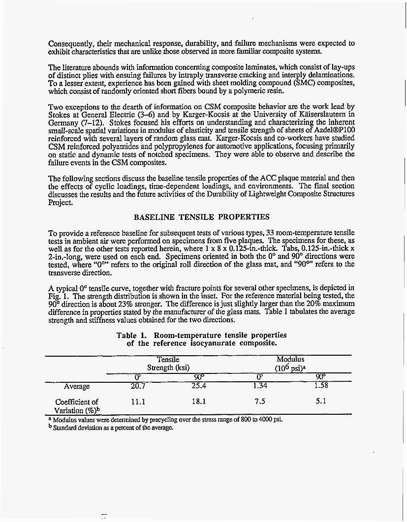
To provide a reference baseline for subsequent tests of various types, 33 room-temperature tensile tests in ambient air were performed on specimens from five plaques. The specimens for these, as well as for the other tests reported herein, where 1 x 8 x 0.125-in.-thick. Tabs, 0.125-in.-thick x 2-in.-long, were used on each end. Specimens oriented in both the 0” and 90” directions were tested, where “Ooy’ refers to the original roll direction of the glass mat, and “90°yy refers to the transverse direction.
A typical 0” tensile curve, together with fracture points for several other specimens, is depicted in Fig. 1. The strength distribution is shown in the inset. For the reference material being tested, the 90” direction is about 23% stronger. The difference is just slightly larger than the 20% maximum difference in properties stated by the manufacturer of the glass mats. Table 1 tabulates the average strength and stiffness values obtained for the two directions.
Table 1. Room-temperature tensile properties of the reference isocyanurate composite.
Tensile Modulus Strength (ksi) (106 psila
cp (P Average 20.7 25.4 1.34 1.58
Coefficient of 11.1 18.1 7.5 5.1 Variation (%)b
Standard deviation as a percent of the average. a Modulus values were determined by precycling over the stress range of 800 to 4000 psi
.--

40000
3oooo
c5 ea a
fn
LE t- u)
- 8 20000
loo00
0 0.00 0.01 0.02 0.03 0.04
STRAIN (Inlln)
Fig. 1. for specimens oriented in the 0' direction.
Room-temperature tensile stress-strain behavior
If virgin specimens are loaded to various fractions of the ultimate strength and then unloaded, the unloading modulus of elasticity is less than the initial loading modulus, the difference being greatest for the most highly loaded specimens. Since modulus reduction may be a measure of internal damage, a series of such tests has been performed and reduction in modulus compared to subsequent ultrasonic C- scan images, which at least qualitatively depict distributed internal damage.
Figure 2 depicts the modulus reduction in several tests where specimens were loaded to 20,40, 60, and 80% of ultimate and then unloaded. Subsequent ultrasonic C-scans of the specimens showed little change from the image of a virgin specimen until a load level of 60% to 80%. Images for 40 and 80% are shown in Fig. 2 together with images of a virgin specimen and a failed specimen. Once the distributed damage appears, little further change is detected up to failure. The dimmer images at the higher load levels, which are more dramatic in color, are presumably the result of matrix cracking and fiber-matrix debonding.
The ability to detect and quantify the initiation and gmwth of damage, to correlate the damage with loading history and environmental effects, and to understand the events leading to failure are key to resolving durability issues. Ultrasonic C-scans of failed fatigue and creep specimens produce images almost identical to those of the damaged tensile specimens shown in Fig. 2. The challenge is to discriminate between the types of damage and to understand the microsmctural events that show up as distributed damage and that ultimately lead to failure. Higher resolution NDE methods, optical and scanning electron microscopy, acoustic emission, and matrix digestion and burn-off techniques are all being explored for these purposes.
CYCLIC FATIGUE BEHAVIOR
Thirty-eight room-temperature fatigue tests were performed on specimens from the same five plaques as used for the tensile tests. The results are shown in Fig. 3. All the tests were at an R value of 0.1 (ratio of minimum to maximum stress). The two run-out points were for maximum stresses of approximately 20% of ultimate. The two tests were stopped after having accumulated 6.0 and 16.0 million cycles for the 0" and 90" directions, respectively, and tensile tests to failure were performed. Reductions in ultimate tensile strength were 36% for the 0" direction and 55% for the 90" direction.
Figure 4 depicts the results of a more systematic matrix of room-temperature tests to determine the degrading effects of prior fatigue cycles on tensile strength. Data for 0" specimens initially cycled at a maximum stress of 60.8% and 40.5% of ultimate are shown. The 0" point discussed in the previous paragraph is also shown. The straight lines are drawn simply as a reference.

2oT- a
0 20
/ 60 I
Fig. 2. Reduction in modulus upon unloading
' i ' from various percentages :of the ultimate tensile , strength and corresponding ultrasonic C-scan images.
I
MAX LOAD (% UTS)
Figure 5 depicts the reduction in stiffness (modulus of elasticity) measured during three of the fatigue tests that were shown in Fig. 3. The specimens were cycled at maximum stresses of 40, 60, or 80% of ultimate. The stiffness decreases are between about 16 and 26% near the end of fatigue life. By considering the widely varying number of cycles to failure (NF), it can be seen that in each test the major portion of the reduction occurred in the first few hundred cycles.
Current activities are focusing on the effects of tempera- and automotive fluids on fatigue and on the consequent strength and stiffness degradation. Interpretation and understanding of the fatigue results and mechanisms will be a key to characterizing the synergistic effects of creep, impact, and environment together with fatigue on strength and stiffness. If will also aid in characterizing cumulative fatigue damage for design. Thus, efforts are underway to identify the microstructural and irreversible changes and their consequences, particularly in the first few fatigue cycles. Ultimately, the goal is to identify the critical material state causing failure and how the progressive microstructural changes from cycle to cycle reach that state.

tn g loo00 a c v)
CYCLES TO FAILURE
0 DIRECTION
2490 Cydes
-I a I 0 8 40- ,198.000
8 60.8XUTS Cycles ' e 40.5Y.UTS
0 21.0%UTS ,50x106
cycles 0 25 50 75 100
% CYCLIC LIFE
E
Fig. 3. Room- temperature fatigue results (R = 0.1).
test
Fig. 4. Degradation in tensile strength due to prior fatigue cycles at the indicated maximum stress levels.
Fig. 5. Reduction in stiffness throughout the life of fatigue tests at the indicated maximum stress levels (Oo direction).
- .- 0 20 i o 60 SO 100
X FATIGUE LIFE

CREEPANDRECOVERY
Creep tests in air have been performed at 10°F, room-temperature, and 250°F. Additional temperatures between -40'F and 250°F, the range of automotive interest, will be addressed in the future. At room-temperature and below the creep response is transient in nature, in that the creep rate becomes negligible at some point in time. At 250°F, on the other hand, the creep response appears to be thermally activated, exhibiting a steady state creep rate. There is little tertiary creep prior to failure.
1-1 I I I I I I I I I I I 0 100 200 300 400 500 600 700
TIME (H)
Fig. 6. Room-temperature, in air, creep curves at several stress levels. LS denotes the measured strain upon loading to the indicated stress level. i
2
z 1 a (1:
Li
0 400 800 1200 1600 2000
Several room- temperature creep curves at stresses ranging from 2.5 to 16.0 ksi are shown in Fig. 6. All specimens were oriented in the 0" direction. No failures have occurred at stresses of 14.5 ksi and below, even in very long tests. Figure 7 shows two creep curves obtained at 250°F in air. Again, the specimens were oriented in the 0" direction.. By comparing Figs. 6 and 7, it can be seen that the higher temperature has a marked effect on creep.
One of the goals of the Durability Project is to develop a damage-based deformation model for predicting time-dependent and cyclic deformation and stiffness response. For this purpose, unloading data provide vital information in the form of modulus change and nonrecoverable permanent strain. Figure 8 shows the results of a typical room-temperature creep recovery test. Here a specimen loaded at 10 ksi was unloaded for periods of recovery. Tests such as this one indicate that while most time-dependent strain is recovered, there is a small permanent nonrecoverable component, probably related to internal damage. More precise tests in this area are underway to help guide the modeling effort.
TIME (H)
Fig. 7. Creep curves in air at 250'F.

1 .o
0.9
0.0 - 0.7 s z 0.6 a a 6 0.5
3 0.4
e 0.3
0.2
0.1
0.0
Y
TIME (H)
Fig. 8. recovery response for a specimen loaded at 10 ksi, then unloaded.
Room-temperature, in air, creep
ENVIRONMENTAL EFFECTS
In addition to the range of temperatures discussed in the previous section, automotive composite structural members may be exposed to a multitude of fluids as well as to vibratory loadings. The effects of these environments are being investigated and quantified. Early results are presented here.
To gain insight into the effects of common automotive fluids, tensile specimens have been soaked in one of eight fluids:
distilled water, saltwater (5% NaCl), 40% antifreeze (ethylene glycol)/60% water, windshield washer fluid (90% methanol), used motor oil, battery electrolyte (34% sulfuric acid), gasoline, and brake fluid (glycols).
Four tensile specimens were removed from each fluid and tested at 1080 h, and four more were removed and tested at 7536 h. The relative changes in strength and stiffness from the unexposed specimen average values are shown in Fig. 9 for those specimens exposed for 7536 h. It appears that battery electrolyte (acid) may have the largest degrading effect on strength, followed by windshield washer fluid and water. Battery electrolyte and windshield washer fluid appear to have the largest effect on stiffness.
Dearlove et al. (1) reported ACC data for both stressed and unstressed specimens exposed to water and windshield washer solvent. Both strength and stiffness were presented. The ACC data were for just a 100 h exposure; nonetheless, the reported effect of washer solvent was to reduce strength and stiffness by almost 40% - considerably larger than the effect shown in Fig. 9. These results indicate that larger experimental populations and careful consideration of the fluid ingredients and composite constituents will be required to reliably characterize fluid environment effects.
r;r , c

0
W (3 -10
$ -20
3 0
-30
I I
Fig. 9. and stiffness (modulus of elasticity) for specimens presoaked for 7536 h.
Fluid effects on strength
Fluid exposure in the presence of load has a dramatic effect on creep and rupture response. For example, Fig. 10 depicts room-temperature creep curves for several specimens subjected to a stress of 10 ksi in different fluid environments. Recall that in air a specimen at 10 ksi would be expected to reach a negligible creep rate and have essentially infinite life. In the presence of automotive fluids, however, there is a significant creep rate and early failures (represented by the Xs). A small part of the deformation in Fig. 10 is probably due to material swelling resulting from fluid sorption. Also, in the case of engine coolant, the effectiveness in accelerating creep depends on the freshness of the solution. When, after a period of time, the old mixture was replaced with new, the creep rate accelerated.
Figure 11 summarizes the dramatic effect that fluids have on creep rupture. The curve represents rupture for specimens in air at room-temperature. As previously stated, specimens at 14.5 ksi would not be
]expected to fail. However, in the presence : of fluids rupture can occur very early at that 1 stress level.
The superposition of small vibratory loads 'on steady creep loads is known to produce accelerated, or vibratory, creep rates in some materials, including polymers (14, 15). Because structural composite components in automotive applications will experience vibratory loadings, the vibratory creep effect is being investigated in the Durability Project. Although the significance of various parameters (frequency, amplitude, temperature) has not been quantified, early tests do show an effect. Figure 12 for example, compares a normal room- temperature creep curve at 14.5 ksi with one which had a vibratory load superimposed. The frequency was chosen as 2200 cpm (representative of an automobile engine) and the amplitude was measured to be approximately 1% of the steady load. The magnitude of creep is probably within the normal scatter, but the rupture life is significantly reduced by the vibratory load.
I
TIME (H)
Fig. 10. Room-temperature creep at 10 ksi in several fluid environments (specimens oriented in the 0' direction).

u)
x, u) u) W a $i
1 10 100 1000 I"
A01 .01 .1
RUPTURE LIFE (H)
d 1:
* 2 t- u)
Fig. 11. at room temperature.
Effect of fluids on rupture life
Fig. 12. (2200 cpm, amplitude 1% of steady load) on creep response at room temperature.
Effect of superimposed vibratory load
TIME (H)
DISCUSSION
Initial results have been presented showing the degrading effects that various loading histones and automotive environments can have on basic properties - strength, stiffness, and dimensional stability - of a candidate automotive structural composite. The goal of the ORNL Durability of Lightweight Composite Structures Project is to quantify these effects and their synergisms and to develop a framework for accounting for them in design.
It was emphasized that a key to characterizing degradation and synergistic effects is an understanding of the various damage mechanisms and how they lead to failure. Tensile tests to various load levels showed that a modulus reduction occurs at each load level and that at between 40 and 80% of the ultimate strength detectable distributed damage occurs. Efforts are underway to understand the nature of this damage and the ultimate failure mechanisms.
In cyclic fatigue, a significant reduction in stiffness occurs in the first few hundred cycles. Presumably, this also is an indication of the initiation and growth of damage. Strength also drops

as the result of prior loading cycles. As in the case of pure tensile loading, efforts are underway to understand the damage and failure mechanisms involved in cyclic fatigue.
At room temperature and below, creep and recovery of the reference CSM material are transient in nature, in that the creep and recovery rates approach zero fairly quickly. At 250°F, on the other hand, creep appears to be more thermally activated, with a steady secondary creep rate being exhibited. The amount of nonrecoverable strain remaining after periods of unloading following creep is thought to be a measure of damage and is thus important to the development of a damage- based deformation model. A significant effort is underway to characterize recovery behavior.
Environmental concerns include the effects of numerous fluids and vibratory loads. Initial results were presented for both. Both tensile strength and creep strength are reduced by common fluids, including water. Vibratory loads superimposed on steady creep loads appear to reduce strength.
There are many facets to the various factors influencing durability. The Durability of Lightweight Structures Project at ORNL is projected to be a five-year effort and is planned to quantify the various effects, .including their synergisms. The six core tasks are
cyclic fatigue, time-dependent creep and rupture, low-energy impacts, environmental effects, damage mechanisms and failure, and modeling and design guidelines.
The current reference material will be used to gain a basic characterization and understanding of the durability issues and effects. The resulting framework will then be adapted to other polymeric composites of interest as they are identified by ACC. Once the durability issues are fully understood and their effects characterized, design guidance can be developed to assure the long- term durability of automotive composite structures.
1.
2.
3.
4.
5.
6.
REFERENCES
Dearlove, T. J., et al. 1994. “Development of Standardized Tests for an Automotive Structural Composites Database,” pp. 555-66 in Proceedings of the 10th Annual ASMIESD Advanced Composites Cogerence, ASM International, Materials Park, Ohio.
Corum, J. M., et al. 1995. Durability of Polymer Matrix Composites for Automotive Structural Applications: A State-ofthe-Art Review, Oak Ridge National Laboratory Report O N - 6 8 69.
Stokes, V. K. 1990 “Random Glass Mat Reinforced Thermoplastic Composites. Part I: Phenomenology of Tensile Modulus Variations,” Polymer Composites 11( l), 32-44.
Stokes, V. K. 1990 “Random Glass Mat Reinforced Thermoplastic Composites. Part 11: Analysis of Model Materials,” Polymer Composites 11( l), 45-55.
Stokes, V. K. 1990 “Random Glass Mat Reinforced Thermoplastic Composites. Part 111: Characterization of the Tensile Modulus,” Polymer Composites 11(6), 342-53.
Stokes, V. K. 1990 “Random Glass Mat Reinforced Thermoplastic Composites. Part IV: Characterization of the Tensile Strength,” Polymer Composites 11(6), 354-67.

7. Karger-Kocsis, J. 1990. “Dynamic Fracture Mechanics of a RIM Polyamide Block Copolymer Reinforced with Glass Strand Mat,” Polym. Bull. 24,341158.
8. Karger-Kocsis, J. 1991. “Environmental Stress Corrosion Behavior of Polyamides and Their Composites with Short Glass Fibers and Glass Swirl Mat,” Polym. Bull. 26, 123-30.
9. Karger-Kocsis, J. 1992. “Fracture and Failure Behavior of Glass Fiber Mat-Reinforced Structural Nylon RIM Composites,” J. Polymer Engineering 11, 153-73.
10. Karger-Kocsis, J. 1992. “Instrumented Impact Testing of a Glass Swirl Mat-Reinforced Reaction Injection-Molded Polyamide Block Co-polymer (NBC),” J. Appl. Polym. Sci. 45, 1595-1 609.
1 1. Karger-Kocsis, J. and Czigany, T. 1993. “Fracture Behavior of Glass-Fiber Mat-Reinforced Structural Nylon RIM Composites Studied by Microscopic and Acoustic Emission Techniques,” J. Mater. Sci. 28(9), 2438-48.
12. Karger-Kocsis, J., and Fejes-Kozma, 2s. 1994. “Damage Zone Development and Failure Sequence in Glass Fiber Mat-Reinforced Polypropylene Under Static Loading Conditions,” Mechanics of Composite Materials 30(1), 8-13
13. Maksimov, R. D., and Urzhumtsev, Yu. S. 1970. “Vibrbcreep of Polymeric Materials - Polyurethane Combined Loading,” (translated from Russian), Mechanics of Polymers 6, 862-870.
14. Fitzgerald, J. J., et al. 1992. “The Effect of Cyclic Stress on Physical Properties of a Poly[Pimethylsiloxane] Elastomer,” Polymer Engineering and Science 32( 18), 1350-1357.
DISCLAIMER
This report was prepared as an account of work sponsored by an agency of the United States Government. Neither the United States Government nor any agency thereof, nor any of their employees, makes any warranty, express or implied. or assumes any legal liability or responsi- bility for the accuracy, completeness, or usefulness of any information. apparatus, product. or process disclosed, or represents that its use would not infringe privately owned rights. Refer- ence herein to any specific commercial product, process, or service by trade name, trademark. manufacturer, or otherwise does not necessarily constitute or imply its endorsement, recom- mendation, or favoring by the United States Government or any agency thereof. The Views and opinions of authors expressed herein do not necessarily state or reflect those of the United States Government or any agency thereof.