dulcometer multi-parameter controller dialog …prominent.us/promx/pdf/dac_203_04_14.pdfdulcometer®...
TRANSCRIPT

DULCOMETER®
Multi-parameter Controller diaLog DACa
Assembly and operating instructions
A1111
Part no. 985250 BA DM 203 04/14 EN
Please carefully read these operating instructions before use! · Do not discard!The operator shall be liable for any damage caused by installation or operating errors!
Technical changes reserved.

General non-discriminatory approach
In order to make it easier to read, thisdocument uses the male form in grammat‐ical structures but with an implied neutralsense. It is aimed equally at both men andwomen. We kindly ask female readers fortheir understanding in this simplification ofthe text.
Supplementary information
Read the following supplementary infor‐mation in its entirety!
The following are highlighted separately inthe document:
n Enumerated lists
Instructions
ð Results of the instructions
Information
This provides important informationrelating to the correct operation of thesystem or is intended to make yourwork easier.
Safety information
Safety information are provided withdetailed descriptions of the endangeringsituation, see Ä Chapter 4.1 ‘Explanationof the safety information’ on page 18
Supplemental instructions
2

Table of contents1 Operating Concept.................................................................................................. 8
1.1 Functions of the keys .................................................................................. 111.2 Changes the set operating language........................................................... 121.3 Acknowledging Error or Warning Messages ............................................... 131.4 Key Lock ...................................................................................................... 13
2 Entries in the [Menu] display................................................................................. 14
3 ID Code................................................................................................................. 153.1 A complete measuring station may comprise the following:......................... 17
4 Safety and Responsibility..................................................................................... 184.1 Explanation of the safety information........................................................... 184.2 General safety notes.................................................................................... 194.3 Intended Use................................................................................................ 204.4 Users' qualifications...................................................................................... 21
5 Functional description........................................................................................... 23
6 Assembly and installation..................................................................................... 246.1 Scope of supply............................................................................................ 266.2 Mechanical Installation................................................................................. 266.2.1 Wall mounting............................................................................................ 266.2.2 Control Panel Installation.......................................................................... 286.3 Electrical installation..................................................................................... 316.3.1 Specification of the threaded connectors.................................................. 326.3.2 Terminal diagram...................................................................................... 336.3.3 Cable Cross-Sections and Cable End Sleeves......................................... 426.3.4 Wall mounting and control panel installation............................................. 436.3.5 Switching of inductive loads...................................................................... 446.3.6 Connect the sensors electrically to the controller...................................... 456.4 Priming to bleeding....................................................................................... 49
7 Commissioning..................................................................................................... 507.1 Switch-on behaviour during commissioning................................................. 507.2 Adjusting the backlight and contrast of the controller display....................... 517.3 Resetting the operating language................................................................ 517.4 Defining metering and control processes..................................................... 51
Table of contents
3
8 Setting measured variables.................................................................................. 528.1 Information on the measured variables........................................................ 538.1.1 Measured Variable pH [mV]...................................................................... 548.1.2 Temperature.............................................................................................. 548.1.3 Measured variable pH [mA]....................................................................... 558.1.4 ORP [mV], ORP [mA]................................................................................ 558.1.5 Chlorine, bromine, chlorine dioxide, chlorite, dissolved oxygen and
ozone......................................................................................................... 568.1.6 Fluoride Measured Variable...................................................................... 588.1.7 Peracetic Acid........................................................................................... 588.1.8 Hydrogen Peroxide.................................................................................... 598.1.9 Conductivity [mA] ..................................................................................... 598.1.10 Temperature [mA], (as main measured variable).................................... 598.1.11 mA General............................................................................................. 608.1.12 Features of the Two-channel Version..................................................... 60
9 Calibration............................................................................................................. 619.1 Calibrating the pH sensor............................................................................. 629.1.1 Selecting the Calibration Process for pH................................................... 659.1.2 2-point pH sensor calibration (CAL).......................................................... 669.1.3 pH sensor calibration (CAL) with an external sample (1-point)................. 709.1.4 Calibration of the pH Sensor (CAL) by [Data Input].................................. 739.2 Calibrating the ORP Sensor......................................................................... 769.2.1 Selecting the calibration process for ORP................................................. 769.2.2 1-point calibration of ORP sensor (CAL)................................................... 769.2.3 Calibration data for ORP sensor (CAL)..................................................... 789.3 Calibrating the Fluoride Sensor.................................................................... 809.3.1 Selection of the calibration process for fluoride......................................... 809.3.2 2-point fluoride sensor calibration (CAL)................................................... 809.3.3 1-point fluoride sensor calibration (CAL)................................................... 829.4 Calibrating Amperometric Sensors............................................................... 849.4.1 Selecting the calibration process for amperometric measured variables. . 859.4.2 Calibrating the slope.................................................................................. 859.4.3 Calibration of zero point............................................................................ 889.5 Calibrating Oxygen Sensors......................................................................... 909.5.1 Selection of the calibration process for the measured variable O2............ 919.5.2 Selection of the calibration process for the measured variable DO.......... 92
Table of contents
4

9.5.3 Zero point calibration for the measured variable DO................................. 949.5.4 DO value calibration for the measured variable DO.................................. 969.6 Measured value [mA general] calibration..................................................... 989.7 Calibrating conductivity................................................................................ 989.8 Calibrating temperature................................................................................ 99
10 Setting the [Control]............................................................................................ 10110.1 Control parameter [Type]......................................................................... 10810.2 Control parameter [System response]...................................................... 10910.3 Control parameter [Setpoint].................................................................... 10910.4 Control parameter [xp].............................................................................. 11010.5 Control parameter [Ti].............................................................................. 11110.6 Control parameter [Td]............................................................................. 11110.7 Control parameter [Add. Basic load]........................................................ 11110.8 Control parameter [Checkout time].......................................................... 11110.9 Control parameter [max. ctrl var.]............................................................. 11110.10 Interference variable............................................................................... 11110.11 Remote setpoint via a 0/4 ... 20 mA analog signal................................. 11410.12 [Parameter switch] via the digital input or [Timer].................................. 116
11 Setting the [Limit values]..................................................................................... 12011.1 Function of the limit values....................................................................... 12011.2 Setting limit value channel 1..................................................................... 12211.2.1 Setting [Limit 1]...................................................................................... 12311.2.2 Setting [Limit 2]...................................................................................... 12311.2.3 Setting [System response].................................................................... 124
12 Setting the [Pumps]............................................................................................ 12512.1 Setting [Pump 1]....................................................................................... 125
13 Setting the [Relays]............................................................................................. 12813.1 Setting Relay 1......................................................................................... 12813.1.1 Function description [Off]...................................................................... 13113.1.2 Functional description of [Relay timer].................................................. 13113.1.3 Function description [Limit 1] or [Limit 2]............................................... 13113.1.4 Functional description of [Limit value 1/2 (control variable)]................. 13113.1.5 Function description of [Cycle].............................................................. 13113.1.6 Functional description of [Pulse length (PWM)] ................................... 132
Table of contents
5
14 Setting [Digital inputs]......................................................................................... 13314.1 Setting [Digital input 1]............................................................................. 133
15 Setting the [mA outputs]..................................................................................... 13615.1 Setting the [mA outputs]........................................................................... 138
16 Function: Data logger......................................................................................... 14016.1 Activating, reading and deleting log books............................................... 14016.2 Configuring log books............................................................................... 14116.2.1 Using the [calibration log book]............................................................. 14116.2.2 Using the [error log book]...................................................................... 14216.2.3 Using the [Data log book] (optional)...................................................... 143
17 [Diagnostics]....................................................................................................... 14617.1 Displaying [logbooks]............................................................................... 14617.1.1 Displaying the [Calibration Log Book]................................................... 14617.1.2 Reading the [Error Log Book]................................................................ 14617.2 Displaying [simulation].............................................................................. 14717.3 Displaying [Device Information]................................................................ 14717.4 Error messages and warning alerts.......................................................... 14817.5 Help texts................................................................................................. 155
18 [Service] ............................................................................................................. 15718.1 Setting the [Wash Timer].......................................................................... 157
19 Setting [Device setup]......................................................................................... 15819.1 Setting the [Language]............................................................................. 15919.2 Setting [Device configuration]................................................................... 16019.3 Setting the [Extended configuration]........................................................ 16019.4 Update...................................................................................................... 16119.5 Setting the [Access code]......................................................................... 162
20 Controller technical data..................................................................................... 163
21 Spare parts and accessories.............................................................................. 16621.1 Spare parts............................................................................................... 16621.2 Accessories.............................................................................................. 167
22 Required formalities............................................................................................ 16822.1 Disposal of used parts.............................................................................. 16822.2 Standards complied with and conformity declaration............................... 168
Table of contents
6
23 Glossary.............................................................................................................. 169
24 Index................................................................................................................... 177
Table of contents
7

1 Operating Concept
A1035
1.
Fig. 1: Operating cross (1) / Active keys appear [black] in the display; inactive keysappear [grey].For example, the following path is illustrated:
Continuous display or [Calibrate] or [Slope]
Continuous display [Calibrate] [Slope]
A1036
Fig. 2: The display changes throughout an action.I. Continuous display 1II. Display 2
III. Display 3IV. Display 4
The function of the keys is described in table Ä Chapter 1.1 ‘Functions of the keys ’on page 11.
= describes as a symbol an action by the operator, that leads to a new possibility foran action.
[Named in the display] = square brackets contain the name that appears identicallyworded in the controller's display.
Use the key to call up further information.
Operating Concept
8
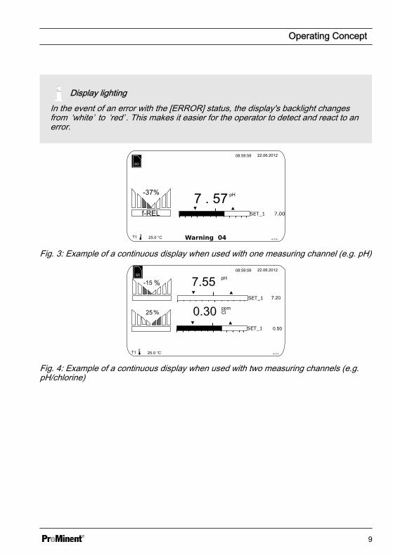
Display lightingIn the event of an error with the [ERROR] status, the display's backlight changesfrom ‘white’ to ‘red’ . This makes it easier for the operator to detect and react to anerror.
Fig. 3: Example of a continuous display when used with one measuring channel (e.g. pH)
A1177
7.557.20
0.50
0.3025
-15
Fig. 4: Example of a continuous display when used with two measuring channels (e.g.pH/chlorine)
Operating Concept
9
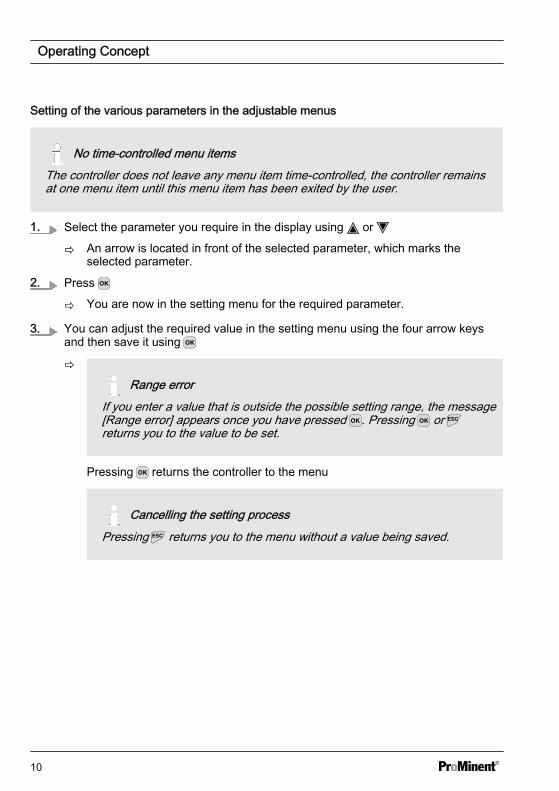
Setting of the various parameters in the adjustable menus
No time-controlled menu itemsThe controller does not leave any menu item time-controlled, the controller remainsat one menu item until this menu item has been exited by the user.
1. Select the parameter you require in the display using or
ð An arrow is located in front of the selected parameter, which marks theselected parameter.
2. Press
ð You are now in the setting menu for the required parameter.
3. You can adjust the required value in the setting menu using the four arrow keysand then save it using
ð
Range errorIf you enter a value that is outside the possible setting range, the message[Range error] appears once you have pressed . Pressing or returns you to the value to be set.
Pressing returns the controller to the menu
Cancelling the setting processPressing returns you to the menu without a value being saved.
Operating Concept
10
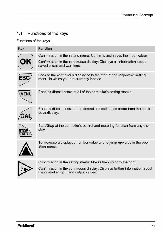
1.1 Functions of the keys Functions of the keys
Key Function
Confirmation in the setting menu: Confirms and saves the input values.
Confirmation in the continuous display: Displays all information aboutsaved errors and warnings.
Back to the continuous display or to the start of the respective settingmenu, in which you are currently located.
Enables direct access to all of the controller's setting menus.
Enables direct access to the controller's calibration menu from the contin‐uous display.
Start/Stop of the controller's control and metering function from any dis‐play.
To increase a displayed number value and to jump upwards in the oper‐ating menu.
Confirmation in the setting menu: Moves the cursor to the right.
Confirmation in the continuous display: Displays further information aboutthe controller input and output values.
Operating Concept
11

Key Function
To decrease a displayed number value and to jump down in the operatingmenu.
Moves the cursor to the left.
1.2 Changes the set operating language1. Simultaneously press the keys and
ð The controller changes to the menu for setting the operating language.
A1482
Language 2
Language
German
Fig. 5: Menu for setting the operating language2. Now using keys and you can set the desired operating language
3. Confirm your selection by pressing the key
ð The controller changes back to the continuous display and indicates theselected operating language.
Operating Concept
12

1.3 Acknowledging Error or Warning Messages If the controller detects an error [Error], the controller is stopped, the backlight switches tored and the alarm relay is deactivated. Acknowledge the message by pressing . Thecontroller displays all the errors and warnings. You can select and acknowledge thepending alarm messages if necessary. When you acknowledge an error, the alarm relayis activated and the backlight switches on again with white light. The error that hasoccurred or the warning message continue to appear in the lower part of the display, e.g.[Error 01], until the cause has been eliminated.
With a warning, for example the controller signals that a sensor has not yet been cali‐brated, it is possible to continue working with the controller with or without acknowledgingthe message.
With an error message [Error], [for example] the controller signals that no sensor hasbeen connected, it is not possible to continue working with the controller once the mes‐sage has been acknowledged. You now have to eliminate the error, see Ä Chapter 17‘[Diagnostics]’ on page 146.
Fig. 6: Alarm message, controller stops the control
1.4 Key Lock The controller has a key lock. If the keylock is activated, the keys cannot bepressed. The key lock can be activated ordeactivated by simultaneously pressing and . An activated key lock is indicatedby the symbol.
Operating Concept
13

2 Entries in the [Menu] display
Name of menu item Jump to chapter
[Measurement] Ä Chapter 8 ‘Setting measured variables’ on page 52
[Limit values] Ä Chapter 11 ‘Setting the [Limit values]’ on page 120
[Control] Ä Chapter 10 ‘Setting the [Control]’ on page 101
[Calibration] Ä Chapter 9 ‘Calibration’ on page 61
[Pumps] Ä Chapter 12 ‘Setting the [Pumps]’ on page 125
[Relays] Ä Chapter 13 ‘Setting the [Relays]’ on page 128
[Digital inputs] Ä Chapter 14 ‘Setting [Digital inputs]’ on page 133
[mA-outputs] Ä Chapter 15 ‘Setting the [mA outputs]’ on page 136
[Diagnostics] Ä Chapter 17 ‘[Diagnostics]’ on page 146
[Service] Ä Chapter 18 ‘[Service] ’ on page 157
[Setup] Ä Chapter 19 ‘ Setting [Device setup]’ on page 158
Entries in the [Menu] display
14
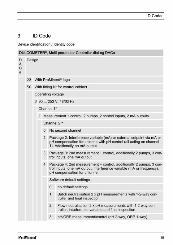
3 ID CodeDevice identification / Identity code
DULCOMETER®, Multi-parameter Controller diaLog DACa
DACa
Design
00 With ProMinent® logo
S0 With fitting kit for control cabinet
Operating voltage
6 90 ... 253 V, 48/63 Hz
Channel 1*
1 Measurement + control, 2 pumps, 2 control inputs, 2 mA outputs
Channel 2**
0 No second channel
2 Package 2: Interference variable (mA) or external setpoint via mA orpH compensation for chlorine with pH control (all acting on channel1). Additionally an mA output.
3 Package 3: 2nd measurement + control, additionally 2 pumps, 3 con‐trol inputs, one mA output
4 Package 4: 2nd measurement + control, additionally 2 pumps, 3 con‐trol inputs, one mA output, interference variable (mA or frequency),pH compensation for chlorine
Software default settings
0 no default settings
1 Batch neutralisation 2 x pH measurements with 1-2-way con‐troller and final inspection
2 Flow neutralisation 2 x pH measurements with 1-2-way con‐troller, interference variable and final inspection
3 pH/ORP measurement/control (pH 2-way, ORP 1-way)
ID Code
15

DULCOMETER®, Multi-parameter Controller diaLog DACa
4 pH/Cl2 measurement/control (pH 2-way, chlorine 1-way)
5 pH/ClO2 measurement/control (pH 2-way, chlorine dioxide 1-way)
6 pH/Cl2 measurement/control with interference variable (pH 2-way, chlorine 1-way)
7 ClO2/ORP measurement/control (chlorine dioxide 1-way, ORPfor monitoring)
Channel connectors
0 Channel 1 / 2 via terminals (mA and mV)
1 Channel 1 via SN 6 coaxial connector (only with pH andORP via mV)
2 Channel 2 via SN 6 coaxial connector (only with pH andORP via mV)
3 Channel 1 and 2 via SN 6 coaxial connector (only with pHand ORP via mV)
Digital sensor / actuator connectors
0 none
Communication
0 none
Data logger
0 No data logger
1 Data logger with measured value visualisationwith SD card
Hardware extension
0 None
1 Protective RC circuit for output relay
Certifications
01 None (CE standard)
ID Code
16
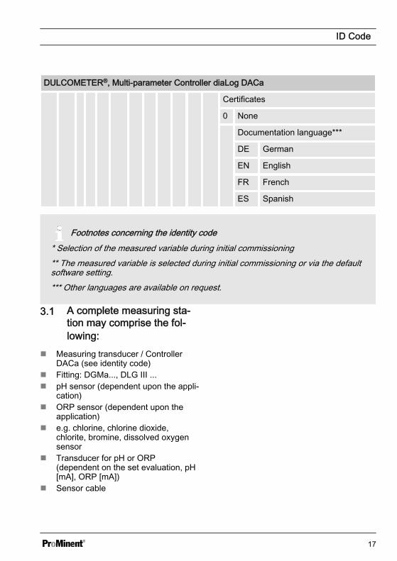
DULCOMETER®, Multi-parameter Controller diaLog DACa
Certificates
0 None
Documentation language***
DE German
EN English
FR French
ES Spanish
Footnotes concerning the identity code* Selection of the measured variable during initial commissioning** The measured variable is selected during initial commissioning or via the defaultsoftware setting.*** Other languages are available on request.
3.1 A complete measuring sta‐tion may comprise the fol‐lowing:
n Measuring transducer / ControllerDACa (see identity code)
n Fitting: DGMa..., DLG III ...n pH sensor (dependent upon the appli‐
cation)n ORP sensor (dependent upon the
application)n e.g. chlorine, chlorine dioxide,
chlorite, bromine, dissolved oxygensensor
n Transducer for pH or ORP(dependent on the set evaluation, pH[mA], ORP [mA])
n Sensor cable
ID Code
17

4 Safety and Responsibility
4.1 Explanation of the safetyinformation
Introduction
These operating instructions provide infor‐mation on the technical data and functionsof the product. These operating instruc‐tions provide detailed safety informationand are provided as clear step-by-stepinstructions.
The safety information and notes are cate‐gorised according to the followingscheme. A number of different symbolsare used to denote different situations.The symbols shown here serve only asexamples.
DANGER!
Nature and source of the dangerConsequence: Fatal or very seriousinjuries.
Measure to be taken to avoid thisdanger
Danger!
– Denotes an immediate threat‐ening danger. If this is disre‐garded, it will result in fatal orvery serious injuries.
WARNING!
Nature and source of the dangerPossible consequence: Fatal or veryserious injuries.
Measure to be taken to avoid thisdanger
Warning!
– Denotes a possibly hazardous sit‐uation. If this is disregarded, itcould result in fatal or veryserious injuries.
CAUTION!
Nature and source of the dangerPossible consequence: Slight orminor injuries, material damage.
Measure to be taken to avoid thisdanger
Caution!
– Denotes a possibly hazardous sit‐uation. If this is disregarded, itcould result in slight or minor inju‐ries. May also be used as awarning about material damage.
Safety and Responsibility
18

NOTICE!
Nature and source of the dangerDamage to the product or its sur‐roundings
Measure to be taken to avoid thisdanger
Note!
– Denotes a possibly damaging sit‐uation. If this is disregarded, theproduct or an object in its vicinitycould be damaged.
Type of informationHints on use and additional informa‐tionSource of the information, additionalmeasuresInformation!– Denotes hints on use and other
useful information. It does notindicate a hazardous or dam‐aging situation.
4.2 General safety notes
WARNING!
Live parts!Possible consequence: Fatal or veryserious injuries
– Measure: Before opening thehousing or before carrying outinstallation work, ensure thedevices are voltage-free.
– Disconnect damaged, defectiveor tampered-with devices fromthe power supply.
WARNING!
Danger from hazardous substances!Possible consequence: Fatal or veryserious injuries.
Please ensure when handling haz‐ardous substances that you haveread the latest safety data sheets pro‐vided by the manufacture of the haz‐ardous substance. The actionsrequired are described in the safetydata sheet. Check the safety datasheet regularly and replace, if neces‐sary, as the hazard potential of a sub‐stance can be re-evaluated at anytime based on new findings.
The system operator is responsiblefor ensuring that these safety datasheets are available and that they arekept up to date, as well as for pro‐ducing an associated hazard assess‐ment for the workstations affected.
Safety and Responsibility
19
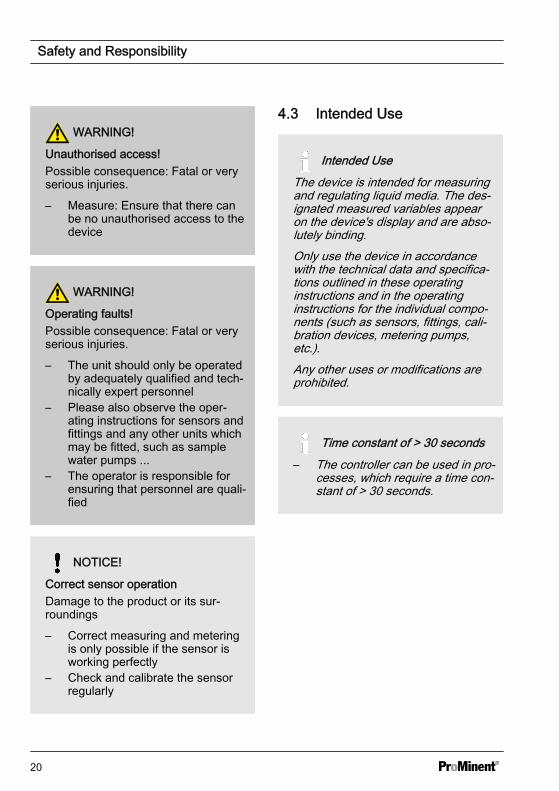
WARNING!
Unauthorised access!Possible consequence: Fatal or veryserious injuries.
– Measure: Ensure that there canbe no unauthorised access to thedevice
WARNING!
Operating faults!Possible consequence: Fatal or veryserious injuries.
– The unit should only be operatedby adequately qualified and tech‐nically expert personnel
– Please also observe the oper‐ating instructions for sensors andfittings and any other units whichmay be fitted, such as samplewater pumps ...
– The operator is responsible forensuring that personnel are quali‐fied
NOTICE!
Correct sensor operationDamage to the product or its sur‐roundings
– Correct measuring and meteringis only possible if the sensor isworking perfectly
– Check and calibrate the sensorregularly
4.3 Intended Use
Intended UseThe device is intended for measuringand regulating liquid media. The des‐ignated measured variables appearon the device's display and are abso‐lutely binding.Only use the device in accordancewith the technical data and specifica‐tions outlined in these operatinginstructions and in the operatinginstructions for the individual compo‐nents (such as sensors, fittings, cali‐bration devices, metering pumps,etc.).Any other uses or modifications areprohibited.
Time constant of > 30 seconds– The controller can be used in pro‐
cesses, which require a time con‐stant of > 30 seconds.
Safety and Responsibility
20
4.4 Users' qualifications
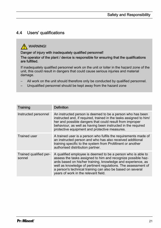
WARNING!
Danger of injury with inadequately qualified personnel!The operator of the plant / device is responsible for ensuring that the qualificationsare fulfilled.
If inadequately qualified personnel work on the unit or loiter in the hazard zone of theunit, this could result in dangers that could cause serious injuries and materialdamage.
– All work on the unit should therefore only be conducted by qualified personnel.– Unqualified personnel should be kept away from the hazard zone
Training Definition
Instructed personnel An instructed person is deemed to be a person who has beeninstructed and, if required, trained in the tasks assigned to him/her and possible dangers that could result from improperbehaviour, as well as having been instructed in the requiredprotective equipment and protective measures.
Trained user A trained user is a person who fulfils the requirements made ofan instructed person and who has also received additionaltraining specific to the system from ProMinent or anotherauthorised distribution partner.
Trained qualified per‐sonnel
A qualified employee is deemed to be a person who is able toassess the tasks assigned to him and recognize possible haz‐ards based on his/her training, knowledge and experience, aswell as knowledge of pertinent regulations. The assessment ofa person's technical training can also be based on severalyears of work in the relevant field.
Safety and Responsibility
21
Training Definition
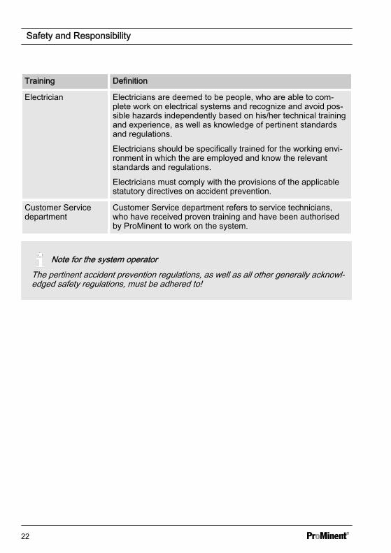
Electrician Electricians are deemed to be people, who are able to com‐plete work on electrical systems and recognize and avoid pos‐sible hazards independently based on his/her technical trainingand experience, as well as knowledge of pertinent standardsand regulations.
Electricians should be specifically trained for the working envi‐ronment in which the are employed and know the relevantstandards and regulations.
Electricians must comply with the provisions of the applicablestatutory directives on accident prevention.
Customer Servicedepartment
Customer Service department refers to service technicians,who have received proven training and have been authorisedby ProMinent to work on the system.
Note for the system operatorThe pertinent accident prevention regulations, as well as all other generally acknowl‐edged safety regulations, must be adhered to!
Safety and Responsibility
22
5 Functional descriptionThe DULCOMETER®
Multi-parameter Controller diaLog DACais a controller platform from ProMinent. Inthe remainder of this document, the term‘controller’ is consistently used for theDULCOMETER®. The controller has beendeveloped for continuous measurementand control of liquid analysis parameters.For water treatment processes in environ‐mental technology and industry. The con‐troller is available in versions with one andtwo measurement channels. The con‐troller can operate together with conven‐tional analog sensors and actuators. Thecontroller is equipped to communicatewith digital sensors and actuators via theCANopen sensor/actuator bus.
Typical applications:
n Potable water treatmentn Waste water treatmentn Industrial and process water treat‐
mentn Swimming pool water treatment
Standard equipment:
n One measuring channel with 14 freelyselectable measured variables (viamV or mA input)
n PID controller with frequency-basedmetering pump control for 2 meteringpumps
n Two analog outputs for measuredvalue, correcting value, or control var‐iable (dependent on the optionalequipment)
n Two digital inputs for sample watererror identification, pause and param‐eter switching
n Two relays with limit value function,timer and discontinuous control, 3-point stepper control (dependent onthe optional equipment)
n Measured variables and languageselection during commissioning
n Temperature compensation for the pHand fluoride measured variables
n 22 operating languagesn Saving and transfer of device para‐
metrisation using an SD cardn Retrospective upgrading of the soft‐
ware function using activation key orfirmware update
n Disturbance variable processing(flow) via frequency
n Measured value trend display via thecontroller display
Optional accessories:
n Second, complete measuring andcontrol channel with 14 freely select‐able measured variables (via mV ormA input)
n PC configuration softwaren Data and event logger with an SD
cardn Disturbance variable processing
(flow) via mAn Compensation of the pH influence on
chlorine measurementn 3 additional inputs, e.g. for level moni‐
toringn PROFIBUS®-DP *.n Modbus-RTUn Visualisation via LAN/WLAN web
access
Functional description
23

6 Assembly and installationn User qualification, mechanical instal‐
lation: trained qualified personnel, seeÄ Chapter 4.4 ‘Users' qualifications’on page 21
n User qualification, electrical installa‐tion: Electrical technician, seeÄ Chapter 4.4 ‘Users' qualifications’on page 21
NOTICE!
Installation position and conditions– The controller meets the require‐
ments for IP 67 degree of protec‐tion (wall-mounted) or IP 54(mounted on the control panel)and NEMA 4X (leak-tightness).These standards are only met ifall seals and threaded connectorsare correctly fitted.
– The (electrical) installation shouldonly take place after (mechanical)installation
– Ensure that there is unimpededaccess for operation
– Ensure safe and low-vibrationfixing
– Avoid direct sunlight– Permissible ambient temperature
of the controller at the installationposition: -20 ... 60 at max. 95% relative air humidity (non-con‐densing)
– Take into consideration the per‐missible ambient temperature ofthe sensors connected and othercomponents
– The controller is only suitable foroperation in closed rooms. Ifoperating outside, use a suitableprotective enclosure to protectthe controller from the environ‐ment
Assembly and installation
24

Read-off and operating position– Install the device in a favourable
position for reading and operating(preferably at eye level).
Mounting position– As standard the controller is wall-
mounted.– Nevertheless you can fit the
controller in a control panelusing the optional fitting kit.
– Always install the controller sothat the cable entries point down‐wards.
– Leave sufficient free space for thecables.
Assembly and installation
25

6.1 Scope of supplyThe following components are included as standard:
Description Quantity
Controller DAC 1
Assembly material, complete, 2P Universal (set) 2
Operating Manual 1
General safety notes 1
6.2 Mechanical Installation
6.2.1 Wall mounting
Mounting materials (contained in thescope of supply)
n 1 x wall bracketn 4 x PT screws 5 x 35 mmn 4 x washers 5.3n 4 x rawl plug Ø 8 mm, plastic
Wall mounting
Take the wall bracket out of the housing
A0490
Fig. 7: Removing the wall bracket1. Pull the two snap hooks (1) out‐
wards
ð The wall brackets snaps slightlydownwards.
2. Push the wall bracket downwards(2) from the housing and fold (3) itout
Assembly and installation
26

3. Use the wall bracket as a drillingtemplate to mark the positions offour drill holes
4. Drill the holes: Ø 8 mm, d = 50 mm
A0491
Fig. 8: Fitting the wall bracket5. Screw the wall bracket into position
using the washers.
A04921
2
3
Fig. 9: Fitting the wall bracket6. Hook the bottom of the housing (1)
into the wall bracket
7. Lightly press the housing at the top(2) against the wall bracket
8. Then check that the housing ishooked in at the top and pressdown (3) until it audibly engages
Assembly and installation
27

6.2.2 Control Panel Installation
CAUTION!
Dimensional variationsPossible consequence: material damage
– Photocopying the punched template can result in dimensional deviations– Use the dimensions shown in Fig. 11 and mark on the control panel
CAUTION!
Material thickness of control panelPossible consequence: material damage
– The material thickness of the control panel must be at least 2 mm to ensuresecure fixing
The perimeter of the housing has a 4 mm wide edge that acts as a stop for the controlpanel, with an additional perimeter groove to accommodate a caulking strip. Whenmounted in the control panel, the entire front face projects about 35 mm from the controlpanel. Install the controller from the outside into a cut-out provided in the control panel forthis purpose. Fix the device to the control panel from the inside using the fittings.
Assembly and installation
28

3 2 1
I.
A1179
Fig. 10: Order number for the DAC control panel fitting kit (included with the scope ofsupply): 1041095.I. Control panel1. 1 x foam rubber caulking strip ∅32. Galvanised steel retaining brackets (6
off)
3. Galvanised PT cutting screws (6 off)Punched template
Assembly and installation
29
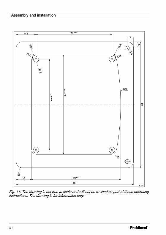
A1170
Fig. 11: The drawing is not true to scale and will not be revised as part of these operatinginstructions. The drawing is for information only.
Assembly and installation
30

1. Determine the precise position of the device on the control panel using the drillingtemplate
2. Mark the corner points and drill (drill diameter 12 - 13 mm)
3. Using a punching tool or jigsaw, match the opening to the punched templatedrawing
4. Chamfer the cut edges and check whether the sealing surfaces are smooth for thecaulking strip
ð Otherwise the seal cannot be guaranteed.
5. Press the caulking strip evenly into the groove running around the device
6. Place the device into the control panel and fix in place at the rear by means of theretaining brackets and PT cutting screws
ð The device should project approx. 35 mm from the control panel
6.3 Electrical installationn User qualification, electrical installa‐
tion: Electrical technician, seeÄ Chapter 4.4 ‘Users' qualifications’on page 21
NOTICE!
Moisture at the contact pointsUse appropriate structural and tech‐nical measures to protect the con‐necting plugs, cables and terminalsfrom moisture. Moisture at the contactpoints can adversely affect the opera‐tion of the device.
Assembly and installation
31
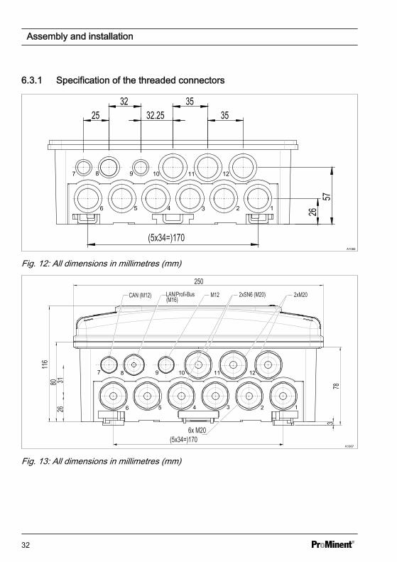
6.3.1 Specification of the threaded connectors
A1066
Fig. 12: All dimensions in millimetres (mm)
A1067
Fig. 13: All dimensions in millimetres (mm)
Assembly and installation
32
6.3.2 Terminal diagram
The controller is supplied with terminal diagrams showing 1:1 assignment.
Only one sensor per unitOnly one sensor can be connected to each of the main unit and extension unit. Forexample, you can connect a chlorine sensor to the main unit (channel 1) and a pHsensor or an interference variable to the extension unit (channel 2).
Connecting the chlorine sensor with controllers with two channelsNote the following when connecting the sensors when measuring chlorine with pHcompensation. Connect the chlorine sensor on the extension unit (channel 2) to theterminals XE8.3 (-) and XE8.4 (+).Connect the pH sensor on the extension unit (channel 1) as follows:– When using a coaxial cable on terminals XE1 (shield), XE 2 (internal conductor)– When using a transmitter pHV1 (mA) on terminals XE4.3 (-) and XE4.4 (+)The pH value also needs to be temperature-compensated to ensure correct pH com‐pensation. Therefore, connect the temperature sensor to terminals XE7.3 and XE7.4.Depending on the identity code of the controller (channel 2 = Package 4), now con‐nect the interference variable on the mA input to the extension unit XE8.2(-) andXE8.3 (+), if not already occupied by the transmitter pHV1 (mA).The interference variable influences the pH and chlorine control.
pH measurement using a transmitterIf a pH measurement is connected to the controller via a transmitterDULCOMETER® DMTa or another manufacturer's pH measuring device, thenassign mA-pH in the DMTa and/or in the other manufacturer's pH measuring deviceas follows:[ 4 mA = pH 15.45] and [20 mA = pH -1.45]
Assembly and installation
33

Connection of the transmitter DTMaA DMTa is connected to the controller as a 2-wire transmitter:– Terminal DACa, channel 1: XE4.3 minus pole and XE4.4 plus pole– Terminal DACa, channel 2: XE8.3 minus pole and XE8.4 plus pole– refer to: Ä ‘Main unit (channel 1) terminal diagram with assignment options ’
on page 36 and Ä ‘Extension unit (channel 2) terminal diagram with assignmentoptions ’ on page 38
An external manufacturer's transmitterConnect an external manufacturer's transmitter as follows to the controller if thetransmitter delivers an active signal:– Terminal DACa, channel 1: XE4.3 plus pole and XE4.4 minus pole– Terminal DACa, channel 2: XE8.3 plus pole and XE8.4 minus pole– refer to: Ä ‘Main unit (channel 1) terminal diagram with assignment options ’
on page 36 and Ä ‘Extension unit (channel 2) terminal diagram with assignmentoptions ’ on page 38
Assembly and installation
34
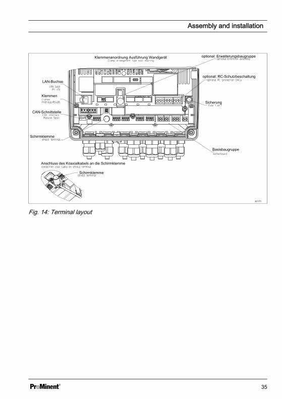
LAN-Buchse
Klemmen
CAN-Schnittstelle
Schirmklemme
Basisbaugruppe
Sicherung
optional: ErweiterungsbaugruppeKlemmenanordnung Ausführung Wandgerät
optional: RC-Schutzbeschaltung
Schirmklemme
Anschluss des Koaxialkabels an die Schirmklemme
A1171
Fig. 14: Terminal layout
Assembly and installation
35

Main unit (channel 1) terminal diagram with assignment options
Schirmklem
me
BelegungsvariantenBelegungsvarianten
Draht- brücke
Optional: externer Anschluss Stecker M
12x1 male
(A-cordiert)
Digitaler Kontakteingang 1
Digitaler Kontakteingang 2
Potenzialfreie Kontakte
Optional: SN-6- Anschlussbuchse
Stromquelle
Sensor
Temperatur
Temperatur
Potenzialausgleich
Normsignal-Eingang
2-Leiter-Normsignal-Eingang
Schirm
Erdung
A1172
Fig. 15: Terminal diagram with assignment options. Main unit, channel 1, there can onlybe one main measured variable, e.g. chlorine sensor, connected to a unit.
Assembly and installation
36
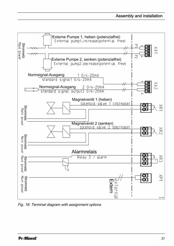
Stromnetz
Stromnetz
Stromnetz
Stromnetz
Stromnetz
Extern
Alarmrelais
Magnetventil 2 (senken)
Magnetventil 1 (heben)
Normsignal-Ausgang
Normsignal-Ausgang
Externe Pumpe 2, senken (potenzialfrei)
Externe Pumpe 1, heben (potenzialfrei)
A1178
Fig. 16: Terminal diagram with assignment options
Assembly and installation
37

Extension unit (channel 2) terminal diagram with assignment options
Extension unit, channel 2, there can only be one main measured variable, e.g. pH, con‐nected to a unit. In addition, the mA -signal of a magnetically inductive flow meter can beconnected depending on the ID code.
Assembly and installation
38
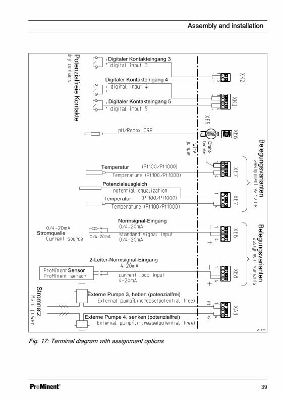
BelegungsvariantenBelegungsvarianten
Draht- brücke
Potenzialfreie Kontakte
Stromnetz
Temperatur
Temperatur
Potenzialausgleich
Digitaler Kontakteingang 5
Digitaler Kontakteingang 4
Digitaler Kontakteingang 3
Normsignal-Eingang
2-Leiter-Normsignal-Eingang
Stromquelle
Sensor
Externe Pumpe 4, senken (potenzialfrei)
Externe Pumpe 3, heben (potenzialfrei)
A1174
Fig. 17: Terminal diagram with assignment options
Assembly and installation
39

Terminal diagram with protective RC circuit (optional)
RC-Schutzbeschaltung
Stromnetz
Stro
mne
tz
Pum
pe 1
(Heb
er)
Pum
pe 2
(Sen
ker)
Stro
mne
tz
Extern
A1180
Fig. 18: Terminal diagram with protective RC circuit (optional)
Assembly and installation
40
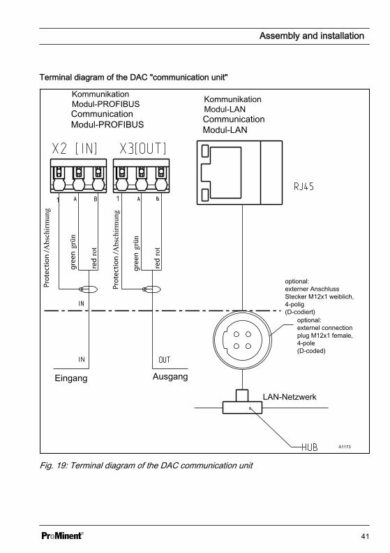
Terminal diagram of the DAC "communication unit"
Kommunikation Modul-PROFIBUS Kommunikation
Modul-LAN
optional: externer Anschluss Stecker M12x1 weiblich, 4-polig (D-codiert)
LAN-Netzwerk
Eingang Ausgang
Abs
chirm
ung
grün
rot Abs
chirm
ung
grün
rot
A1173
Fig. 19: Terminal diagram of the DAC communication unit
Assembly and installation
41
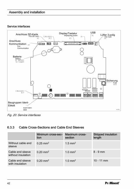
Service interfaces
Sicherung
Lüfter 3-poligUSBDisplay/TastaturAnschluss SD-Karte
Anschluss Kommunikation
Batterie
Baugruppen Ident- Etikett
A1175
Fig. 20: Service interfaces
6.3.3 Cable Cross-Sections and Cable End Sleeves
Minimum cross-sec‐tion
Maximum cross-section
Stripped insulationlength
Without cable endsleeve
0.25 mm2 1.5 mm2
Cable end sleevewithout insulation
0.20 mm2 1.0 mm2 8 - 9 mm
Cable end sleevewith insulation
0.20 mm2 1.0 mm2 10 - 11 mm
Assembly and installation
42
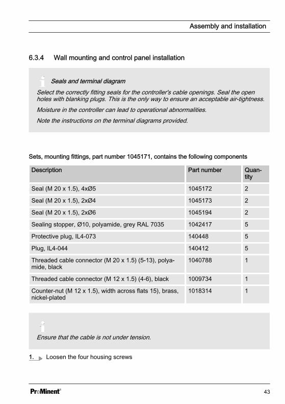
6.3.4 Wall mounting and control panel installation
Seals and terminal diagramSelect the correctly fitting seals for the controller's cable openings. Seal the openholes with blanking plugs. This is the only way to ensure an acceptable air-tightness.Moisture in the controller can lead to operational abnormalities.Note the instructions on the terminal diagrams provided.
Sets, mounting fittings, part number 1045171, contains the following components
Description Part number Quan‐tity
Seal (M 20 x 1.5), 4xØ5 1045172 2
Seal (M 20 x 1.5), 2xØ4 1045173 2
Seal (M 20 x 1.5), 2xØ6 1045194 2
Sealing stopper, Ø10, polyamide, grey RAL 7035 1042417 5
Protective plug, IL4-073 140448 5
Plug, IL4-044 140412 5
Threaded cable connector (M 20 x 1.5) (5-13), polya‐mide, black
1040788 1
Threaded cable connector (M 12 x 1.5) (4-6), black 1009734 1
Counter-nut (M 12 x 1.5), width across flats 15), brass,nickel-plated
1018314 1
Ensure that the cable is not under tension.
1. Loosen the four housing screws
Assembly and installation
43

2. Slightly lift the top section of the housing forwards and plug the housing top sectionin the park position in the housing bottom section.
3.
Large threaded connection (M 20 x 1.5)Small threaded connection (M 12 x 1.5)
4. Guide the cable into the controller.
5. Connect the cable as indicated on the terminal diagram
6. Tighten the clamping nuts of the threaded connections so that they are properlysealed
7. Place the upper section of the housing onto the lower section of the housing.
8. Manually tighten the housing screws
9. Check once again that the seal is properly fitted. The degree of protection IP 67(wall/pipe-mounted) or IP 54 (control pane-mounted) can only be assured if themounting is correct.
6.3.5 Switching of inductive loads
If you connect an inductive load, i.e. aconsumer which uses a coil (e.g. analpha motorised pump), then youmust protect your controller with aprotective circuit. If in doubt, consultan electrical technician for advice.
The RC member protective circuit is asimple, but nevertheless very effective,circuit. This circuit is also referred to as asnubber or Boucherot member. It is pri‐marily used to protect switching contacts.
When switching off, the connection inseries of a resistor and capacitor meansthat the current can be dissipated in adamped oscillation.
Also when switching on, the resistor actsas a current limiter for the capacitorcharging process. The RC member pro‐tective circuit is highly suitable for ACvoltage supplies.
Assembly and installation
44

The magnitude of the resistance R ofthe RC member is determined accordingto the following equation:
R=U/IL(Where U= Voltage across the load andIL = current through the load)
The magnitude of the capacitor is deter‐mined using the following equation:
C=k * ILk=0,1...2 (dependent on the application).
Only use capacitors of class X2.
Units: R = Ohm; U = Volt; IL = Ampere;C = µF
If consumers are connected whichhave a high starting current (e.g. plug-in, switched mains power supplies),then a means of limiting the startingcurrent must be provided.
The switching-off process can be investi‐gated and documented using an oscillo‐scope. The voltage peak at the switchcontact depends on the selected RC com‐bination.
A0842
Fig. 21: Switching-off process shown onthe oscillogram.
A0835
Fig. 22: RC protective circuit for the relaycontactsTypical AC current application with aninductive load:
n 1) Load (e.g. alpha motor-drivenpump)
n 2) RC-protective circuit– Typical RC protective circuit at
230 V AC:– Capacitor [0.22µF/X2]– Resistance [100 Ohm / 1 W]
(metal oxide (pulse resistant))n 3) Relay contact (XR1, XR2, XR3)
6.3.6 Connect the sensors electri‐cally to the controller
User qualification, electrical installation:Electrical technician, see Ä Chapter 4.4‘Users' qualifications’ on page 21
Ready-made coaxial cable
If possible, only use ready-madecoaxial cables that you can selectfrom the Product Catalogue.– Coaxial cable 0.8 mm, ready-
made, order no. 1024105– Coaxial cable 2 m-SN6, ready-
made, order no.– Coaxial cable 5 m-SN6, ready-
made, order no.
Assembly and installation
45
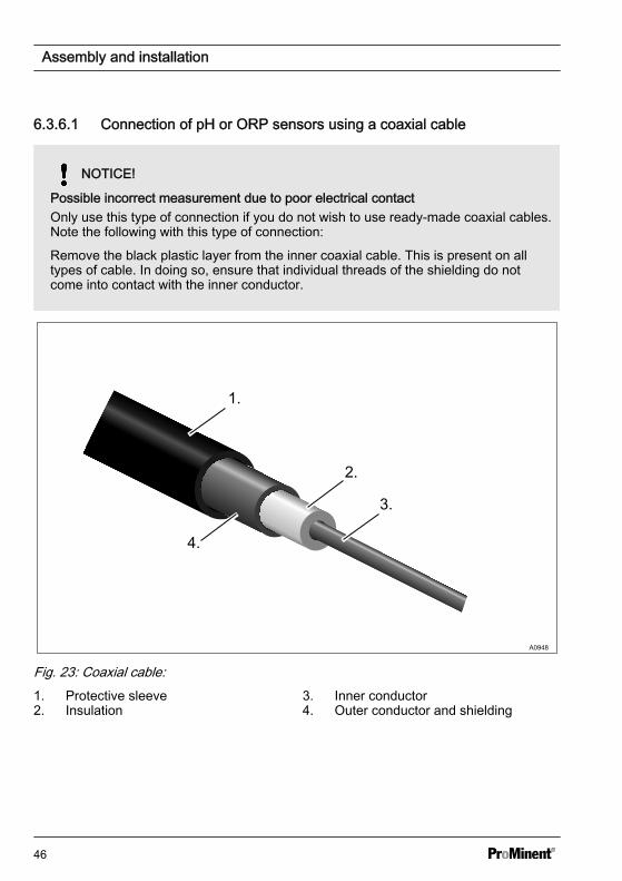
6.3.6.1 Connection of pH or ORP sensors using a coaxial cable
NOTICE!
Possible incorrect measurement due to poor electrical contactOnly use this type of connection if you do not wish to use ready-made coaxial cables.Note the following with this type of connection:
Remove the black plastic layer from the inner coaxial cable. This is present on alltypes of cable. In doing so, ensure that individual threads of the shielding do notcome into contact with the inner conductor.
1.
2.
3.
4.
A0948
Fig. 23: Coaxial cable:1. Protective sleeve2. Insulation
3. Inner conductor4. Outer conductor and shielding
Assembly and installation
46
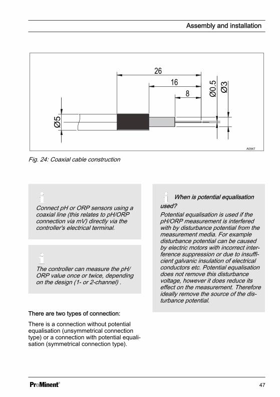
A0947
Fig. 24: Coaxial cable construction
Connect pH or ORP sensors using acoaxial line (this relates to pH/ORPconnection via mV) directly via thecontroller's electrical terminal.
The controller can measure the pH/ORP value once or twice, dependingon the design (1- or 2-channel) .
There are two types of connection:
There is a connection without potentialequalisation (unsymmetrical connectiontype) or a connection with potential equali‐sation (symmetrical connection type).
When is potential equalisationused?Potential equalisation is used if thepH/ORP measurement is interferedwith by disturbance potential from themeasurement media. For exampledisturbance potential can be causedby electric motors with incorrect inter‐ference suppression or due to insuffi‐cient galvanic insulation of electricalconductors etc. Potential equalisationdoes not remove this disturbancevoltage, however it does reduce itseffect on the measurement. Thereforeideally remove the source of the dis‐turbance potential.
Assembly and installation
47
Switch the controller to measurement withpotential equalisation
NOTICE!
Wire jumper with connected potentialequalisationA measurement with a wire jumperand connected potential equalisationdelivers incorrect measured values.
Please note the following differ‐ences:The controller is factory-preset formeasurements without potentialequalisation (unsymmetrical measure‐ment).When measuring with potential equal‐isation (symmetrical measurement),the setting in the [Measurement]menu has to be changed accordingly.With a symmetrical connection,remove the wire jumper and connectthe potential equalisation conductor(PA) to the terminal XE3_2 (channel1) or XE7_2 (channel 2) of the con‐troller.
1. In the [Measurement] channel 1 or2 menu change the entry under[Potential equalisation] to [Yes]
2. Open the controller and remove thewire jumper
n Terminal XE3_1, XE3_2 forchannel 1
n Terminal XE7_1, XE7_2 forchannel 2
Sensor connection without potentialequalisation
The sensor is connected to the controller,as marked on the terminal diagram. Donot remove the wire jumper in the con‐troller.
Sensor connection with potential equalisa‐tion
NOTICE!
Error sources when measuring withpotential equalisationA measurement without a wire jumperand/or unconnected potential equali‐sation delivers incorrect measuredvalues.
With a symmetrical connection, con‐nect the line for potential equalisationto terminal XE3_2 (channel 1) orXE7_2 (channel 2) in the controller.Before doing so, remove the respec‐tive wire jumper from these terminals.
Assembly and installation
48

Potential equalisation always has tobe in contact with the measuringmedium. A special potential equalisa‐tion plug (Order No. 791663) and acable (Order No. 818438) are neces‐sary with fitting DGMa. The potentialequalisation pin is always fitted withfitting DLG, only the cable(Order No. 818438) is necessary.
Peculiarities when calibratingwith potential equalisationWhen calibrating, immerse the poten‐tial equalisation pin in the respectivebuffer solution, or use the calibrationreceptacle which forms part of thescope of supply of the DGMa fitting.This calibration receptacle incorpo‐rates an inbuilt potential equalisationpin to which you can connect thepotential equalisation line.
6.3.6.2 Connection of ampero‐metric sensors
Connect the sensor, as described in thesensor operating instructions, to the corre‐sponding terminals of the controller, seeÄ Chapter 6.3.2 ‘Terminal diagram’on page 33.
6.4 Priming to bleeding
The pump is working at 100%performanceNote any installation work in your sur‐roundings, as feed chemical canuncontrollably escape into the envi‐ronment in the event of open pipesetc.
Pump 1
A1068
Function Decrease valueMax. stroke rate Assignment Channel 1
Fig. 25: [Prime with <OK>] e.g. to bleed apumpIf you select the function[Prime with <OK>] when the pumps areconnected and operable, the pumps con‐tinue to operate at 100% power for aslong as you press and hold down the key.
You can use this function, for example, totransport the feed chemical to the pump,thereby bleeding the metering line.
Assembly and installation
49
7 Commissioningn User qualification: trained user, see
Ä Chapter 4.4 ‘Users' qualifications’on page 21
WARNING!
Sensor run-in periodThis can result in hazardous incorrectmetering
Take into consideration the sensor'srun-in period during commissioning:
– There has to be adequate feedchemical in the sample water foryour application (e.g. 0.5 ppmchlorine)
– Correct measuring and meteringis only possible if the sensor isworking perfectly.
– It is imperative that you adhere tothe sensor's run-in periods.
– Calculate the run in period whenplanning commissioning.
– It may take a whole working dayto run in the sensor.
– Refer to the sensor's operatinginstructions.
After mechanical and electrical installa‐tion, integrate the controller into the meas‐uring point.
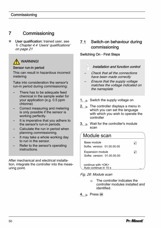
7.1 Switch-on behaviour duringcommissioning
Switching On - First Steps
Installation and function control– Check that all the connections
have been made correctly– Ensure that the supply voltage
matches the voltage indicated onthe nameplate
1. Switch the supply voltage on
2. The controller displays a menu inwhich you can set the languagewith which you wish to operate thecontroller
3. Wait for the controller's modulescan
Module scan
A1081
Base module
Expansion module
continue with <OK>
Softw. version: 01.00.00.00
Softw. version: 01.00.00.00
Auto continue in 10 s
Fig. 26: Module scan
ð The controller indicates thecontroller modules installed andidentified.
4. Press
Commissioning
50

ð The controller now changes toits continuous display. From thecontinuous display, you canaccess all the controller's func‐tions using .
7.2 Adjusting the backlight andcontrast of the controller dis‐play
Continuous display [Setup] [Device setup] or
[Device configuration] [Backlight]Under this menu item you can set thebrightness and contrast of your controllerdisplay to match the ambient conditions atyour installation location.
7.3 Resetting the operating lan‐guage
Resetting the operating lan‐guageIn the event that a foreign and henceincomprehensible operating languagehas been set, the controller can bereset to the basic setting. This isimplemented by the simultaneouspressing of the and keys.If you no longer know whereaboutsyou are in the operator menu, youmust press the key as often asnecessary until the continuous displaybecomes visible again.
7.4 Defining metering and con‐trol processes
Set the controller once you have inte‐grated it into the control circuit. Setting thecontroller adapts it to your process.
Define the following parameters to set upa controller:
n What type of a process is planned?n Which measured variables are there?n Is there an in-line, batch or circulation
process planned?n Should the controller operate as a
one-way or two-way control?n Which control variables are there?n What control parameters are neces‐
sary?n What should the controller do in
[HOLD]?n How should the actuators be con‐
trolled?n How should the mA-outputs be set?
Commissioning
51

8 Setting measured variablesn User qualification: trained user, see Ä Chapter 4.4 ‘Users' qualifications’ on page 21Continuous display or [Measurement] [Measurement] or [Meas. channel 1] or [Measured variable]
Settings for [Channel 2]In its 2-channel version, the controller has two measurement channels. This descrip‐tion for [Channel 1] applies correspondingly for the settings in [Channel 2]. The pro‐cedure for making the settings for the channel in question is identical, however theparameters to be set may be different. Differences are pointed out and are alsodescribed.
Channel 1Measured variable
A1082
ChlorineSensor typeMeasuring rangeTemperatureProcess temperaturepH compensation
CLE3/CLE3.10... 2.0 ppmManual10.0 °COff
Fig. 27: Setting measured variables, using the example of [Channel 1] and the measuredvariable [Chlorine]
The following measured variables can be set at the controller:
Measured variable Meaning Unit
[None] The controller does not carry out anymeasurement.
[pH [mV]] pH sensor with mV signal [pH]
[pH [mA]] pH sensor with mA signal [pH]
[ORP [mV]] ORP sensor with mV signal [mV]
[ORP [mA]] ORP sensor with mA signal [mV]
Setting measured variables
52

Measured variable Meaning Unit
[mA general] n [Freely selectable]n [%]n [mA]n [m]n [bar]n [psi]n [m3/h]n [gal/h]n [ppm]n [%RF]n [NTU]
[Bromine] Bromine [ppm]
[Chlorine] Chlorine [ppm]
[Chlorine dioxide] Chlorine dioxide [ppm]
[Chlorite] Chlorite [ppm]
[Fluoride [mA]] Fluoride [ppm]
[Oxygen] Oxygen [ppm]
[Ozone] Ozone [ppm]
[Peracetic acid] Peracetic acid [ppm]
[Hydrogen per.] Hydrogen peroxide with a [PER]sensor type
[ppm]
[Cond. (mA)] Conductivity sensor with mA signal [µS]
[Temp. [mA]] Temperature sensor with mA signal [°C] or [°F]
[Temp.[Pt100x]] Temperature with a Pt 100 or Pt 1000sensor type
[°C] or [°F ]
When you perform the measurement of the pH value with potential equalisation, youhave to set this procedure when selecting the measured variable as a parameter.
Setting measured variables
53

8.1 Information on the measuredvariables
Existing measured variablesAll possible measured variables areavailable in the controller and can beused.
8.1.1 Measured Variable pH [mV]
The measured variable pH [mV]
The pH sensor of the measured variablepH [mV] is connected using a coaxialcable via which the mV signal is trans‐mitted to the controller. This measurementcan be used if the cable is less than 10metres in length.
Decimal places
The function shows the pH value in thedisplay with one or two decimal places. Anadaptation of the display to one decimalplace makes sense if a change in the1/100 value is unimportant or if the valueis unsteady.
Factory setting: 2 decimal places
Glass break detection
[ON] / [OFF] : Switches glass break detec‐tion of the pH sensor [ON] or [OFF]. Thefactory setting is [OFF]. If the controllerhas the setting [ON], it displays an errormessage if an error is detected.
The function [Glass break detection]increases the safety of the measuringpoint.
Cable break detection
[ON] / [OFF] : Switches cable break detec‐tion of the coaxial cable [ON] or [OFF].The factory setting is [OFF]. If the con‐troller has the setting [ON], it displays analarm message if an error is detected.
The function [Cable break detection]increases the safety of the measuringpoint.
8.1.2 Temperature
Temperature
With amperometric measured variables,the temperature influence on the meas‐urement is automatically compensated inthe sensor. A separate temperature meas‐urement is only used, if necessary, to dis‐play and issue the temperature values viaan mA-output. Separate temperature com‐pensation is only needed with a chlorinedioxide sensor type CDP.
Temperature compensation
This function is used for compensation ofthe temperature influence of the processon measurement.
Temperature: [Off] / [Manual] / [Automatic]
n [Off] switches the process tempera‐ture setting off
n [Manual] makes possible a manualspecification of the process tempera‐ture
n [Automatic] uses a measured processtemperature. Automatic measurementof the temperature using the tempera‐ture sensor, e.g. Pt1000. For pH,CDP and fluoride, temperature com‐pensation can be switched [ON] or[OFF] in the menu.
Setting measured variables
54
8.1.3 Measured variable pH [mA]
Measured variable pH [mA]:
If the measured variable ‘pH [mA]’ , i.e.pH measurement using a mA signal, isselected, then the possibility of sensormonitoring for cable or glass breaks is nolonger available.
For a pH measurement using a mA signal,either a DMTa or a pH-V1 measuringtransducer is connected to the pH sensor.A 2-conductor connection cable is usedbetween the DMTa-/pH-V1 measuringtransducer and the controller. The con‐nection cable supplies the DMTa-/pH-V1measuring transducer and routes themeasured value as a 4 ... 20 mA signal tothe controller.
When using the DMTa measuring trans‐ducer or the measuring transducer ofanother supplier, the measuring rangeallocation must be set to the followingvalues:
n 4 mA = 15.45 pHn 20 mA = -1.45 pH
With a pH-V1 measuring transducer, thesetting of the measuring range allocationis automatically specified.
Temperature compensation
This function is used to compensate forthe temperature influence on the meas‐urement. The process temperature is setin the DMTa measuring transducer whenusing a DMTa measuring transducer
Temperature: [Off] / [Manual] / [Automatic]
n [Off] switches the process tempera‐ture setting off
n [Manual] permits manual processtemperature setting
n [Automatic] uses a measured processtemperature
8.1.4 ORP [mV], ORP [mA]
Measured variables ORP [mV], ORP [mA]
If the measured variable ‘ ORP [mV]’ or‘ORP [mA]’ is selected, measurement ofthe process temperature is only possiblefor information or recording purposes.
For the measured variable ‘ORP [mV]’ ,the measuring range is fixed in the range-1500 mV ... + 1500 mV.
For the measured variable ‘ORP [mA]’ ,the measuring range is dependent on theRH-V1 measuring transducer and is 0 ...+1000 mV.
Setting measured variables
55
8.1.5 Chlorine, bromine, chlorinedioxide, chlorite, dissolvedoxygen and ozone
Measured variable chlorine, bromine,chlorine dioxide, chlorite, dissolvedoxygen and ozone:
The measured variables chlorine , bro‐mine, chlorine dioxide, chlorite, dissolvedoxygen and ozone are always measuredusing a mA signal because the measuringtransducer is located in the sensor.
The temperature compensation takesplace automatically inside the sensor(exception: CDP, chlorine dioxide sensor).For further information see the operatinginstructions of the sensor used.
Measurement of chlorine with pH compen‐sation
Chlorine for disinfecting water is availablein different forms, for example as liquidsodium-calcium hypochlorite, as dissolvedcalcium hypochlorite or as chlorine gas.All these forms can be measured withDULCOTEST chlorine sensors. Afterchlorine has been added to water, thechlorine splits into two parts depending onthe pH value:
n 1. into hypochlorous acid (also knownas HOCI) – a strongly oxidising disin‐fectant that destroys most organismsin a very short time.
n 2. into the hypochlorite anion (OCI) –with a weak disinfectant effect thattakes a very long time to destroyorganisms.
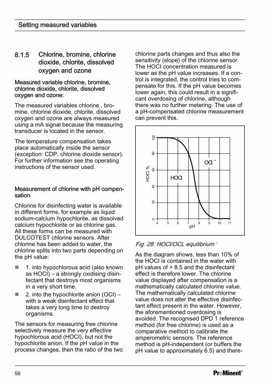
The sensors for measuring free chlorineselectively measure the very effectivehypochlorous acid (HOCI), but not thehypochlorite anion. If the pH value in theprocess changes, then the ratio of the two
chlorine parts changes and thus also thesensitivity (slope) of the chlorine sensor.The HOCI concentration measured islower as the pH value increases. If a con‐trol is integrated, the control tries to com‐pensate for this. If the pH value becomeslower again, this could result in a signifi‐cant overdosing of chlorine, althoughthere was no further metering. The use ofa pH-compensated chlorine measurementcan prevent this.
4 5 6 7 8 9 10 11
020
4060
8010
0
OCl -
HOClHO
Cl %
pH
Fig. 28: HOCl/OCL equilibrium -
As the diagram shows, less than 10% ofthe HOCI is contained in the water withpH values of > 8.5 and the disinfectanteffect is therefore lower. The chlorinevalue displayed after compensation is amathematically calculated chlorine value.The mathematically calculated chlorinevalue does not alter the effective disinfec‐tant effect present in the water. However,the aforementioned overdosing isavoided. The recognised DPD 1 referencemethod (for free chlorine) is used as acomparative method to calibrate theamperometric sensors. The referencemethod is pH-independent (or buffers thepH value to approximately 6.5) and there‐
Setting measured variables
56

fore records the free chlorine as almost100 % HOCI. To ensure that the concen‐tration value measured by the ampero‐metric chlorine measuring system corre‐sponds to this free chlorine value, the pHinfluence on the chlorine value measuredby the sensor can be compensated by thecontroller. The controller can either per‐form this pH compensation automatically,via an integrated pH-measurement, ormanually based on a fixed pH value. Werecommend the automatic version. Indoing so, it is imperative that you alsomeasure the sample water temperature,which has a significant influence on thepH measurement. If this influence has notbeen compensated, the pH value wouldbe measured incorrectly and the chlorinevalue would therefore also be incorrectlycompensated.
No calibration is possible at high pHvalues without pH compensation, becausethe difference between the measurementusing the chlorine sensor and the compa‐rative DPD 1 reference method is toogreat.
The operational pH calibration range is:pH 4.00 ... 8.50, Temperature: 5 ... 45 °C
Calibration of the chlorinesensor with activated pH compensa‐tionIt is imperative that you always cali‐brate the pH sensor first before thechlorine sensor. The chlorine sensoralways needs to be calibrated any fur‐ther time the pH sensor has to be cali‐brated. Otherwise the chlorine meas‐urement will be incorrect.
Sensor type:
First select the sensor type. The sensortype is given on the sensor nameplate.This sensor selection is necessary andactivates the sensor-specific data in thecontroller.
Measuring range of the sensors
Select the measuring range. The meas‐uring range is given on the sensor name‐plate. An incorrect measuring range leadsto an incorrect measurement.
Temperature
The temperature measurement is usedonly for information and recording pur‐poses, but not for temperature compensa‐tion. Temperature compensation is per‐formed in the sensor. If the measuredvariable [Chlorine dioxide] and the [CDP]type of sensor have been selected, then aseparate temperature measurement isneeded for temperature compensation.
Setting measured variables
57
8.1.6 Fluoride Measured Variable
Fluoride Measured Variable
When measuring fluoride as the meas‐ured variable, the sensor signal is con‐verted into a 4 - 20 mA signal by a FPV1or FP100V1 measuring transducer,depending on the measuring range. Themeasuring transducer is connected to thecontroller's mA input. The REFP-SE refer‐ence sensor is connected to the meas‐uring transducer using a coaxial cablewith an SN 6 plug.
FPV1 measuring transducer: Measuringrange 0.05 ...10 mg/l.
FP100V1 measuring transducer: Meas‐uring range 0.5 ... 100 mg/l.
Measuring range of the measuring trans‐ducer
Select the measuring range. The meas‐uring range is printed on the nameplate ofthe measuring transducer. An incorrectmeasuring range will lead to an incorrectmeasurement.
Temperature compensation
This function is used for compensation ofthe temperature influence of the processon measurement.
Temperature: [Off] / [Manual] / [Automatic]
n [Off] switches the process tempera‐ture setting off
n [Manual] makes possible a manualspecification of the process tempera‐ture
n [Automatic] uses a measured processtemperature. Automatic measurementof the temperature using the tempera‐ture sensor, e.g. Pt1000. For pH,CDP and fluoride, temperature com‐pensation can be switched [ON] or[OFF] in the menu.
8.1.7 Peracetic Acid
Peracetic acid measured variable
Peracetic acid as a measured variable ismeasured via one of the two mA sensorinputs. Temperature compensation is per‐formed in the sensor. An additionally con‐nected temperature sensor is only usedfor display and data recording with a datalogger and can be issued on a mA-outputvia field bus or web server.
Measuring range of the sensors
Select the measuring range. The meas‐uring range is given on the sensor name‐plate. An incorrect measuring range leadsto an incorrect measurement.
Setting measured variables
58
Temperature
The temperature measurement is usedonly for information or recording purposes,but not for temperature compensation.Temperature compensation is carried outin the sensor.
8.1.8 Hydrogen Peroxide
Hydrogen peroxide as a measured vari‐able [mA]
Hydrogen peroxide as a measured vari‐able is measured via one of the two mAsensor inputs. Temperature compensationis performed in the sensor. An additionallyconnected temperature sensor is onlyused for display and data recording with adata logger and can be issued on a mA-output via field bus or web server.
Measuring range of the sensors
Select the measuring range. The meas‐uring range is given on the sensor name‐plate. An incorrect measuring range leadsto an incorrect measurement.
Temperature
The temperature measurement is usedonly for information or recording purposes,but not for temperature compensation.Temperature compensation is carried outin the sensor.
8.1.9 Conductivity [mA]
Measured variable conductivity [mA]
When measuring conductivity [mA], use ofa measuring transducer is a prerequisite,e.g. a measuring transducer DMTa con‐ductivity. A conductivity sensor cannot bedirectly connected to the controller.
Measuring range:
n Select the measuring range corre‐sponding to the measuring range ofthe measuring transducer used. Anincorrect measuring range leads to anincorrect measurement.
Temperature:
n The temperature measurement isused only for information or recordingpurposes, but not however for tem‐perature compensation. Temperaturecompensation is carried out in themeasuring transducer.
8.1.10 Temperature [mA], (asmain measured variable)
Measured variable temperature [mA], (asmain measured variable):
For the measured variable ‘Temperature[mA]’ use of a DMTa temperature meas‐uring transducer or a Pt100V1 measuringtransducer is prerequisite. The measuringrange is: 0 ... 100 °C. A temperaturesensor cannot be connected directly to thecontroller.
Setting measured variables
59
8.1.11 mA General
Measured variable [mA general]
With the [mA general] measured variable,various preselected measured variablecan be selected and/or one measured var‐iable can also be freely edited with its unitof measure. The temperature measure‐ment cannot be used for compensationpurposes, because the influence of thetemperature measurement on the meas‐ured value is not known. In principle, thesettings are performed in the same wayas with the other measured variable. Astandardised calibrated signal is expectedby the controller from each connecteddevice
8.1.12 Features of the Two-channel Version
Two channel version
If a second measuring channel is avail‐able (dependent on the identity code,channel 2), then this second measuringchannel can be configured according tothe descriptions of the first measuringchannel.
Two channel version with two identicalmeasured variables
If the measured variables of measuringchannel 1 and measuring channel 2 arechosen identically, then the menu item[Differential meas]appears in the[Measurement] menu. The[Differential meas] function is switched off"ex works". The function[Differential meas] can be activated andthe calculation [K1-K2] executed. Theresult of the calculation is displayed in themain display 2 by pressing the key or
key. By pressing the or key againyou jump back to the main display 1. Thelimit value criteria for the[Differential meas] can be set in the menu[Limit values].
Setting measured variables
60
9 Calibrationn User qualification: instructed user,
see Ä Chapter 4.4 ‘Users' qualifica‐tions’ on page 21
Settings for [Channel 2]In its 2-channel version, the controllerhas two measurement channels. Thisdescription for [Channel 1] appliescorrespondingly for the settings in[Channel 2]. The procedure formaking the settings for the channel inquestion is identical, however theparameters to be set may be different.Differences are pointed out and arealso described.
Display tolerancesDisplay tolerances between thesensor and/or measuring device andcontroller have to be calibrated withsensors and/or with output signals ofmeasuring devices that do not requirecalibration or where calibration is per‐formed in the sensor/measuringdevice. The relevant information forthis is contained in the respectiveoperating instructions for the sensoror measuring device.
Continuous display Menu or [Calibration]
or
Continuous display
A1606
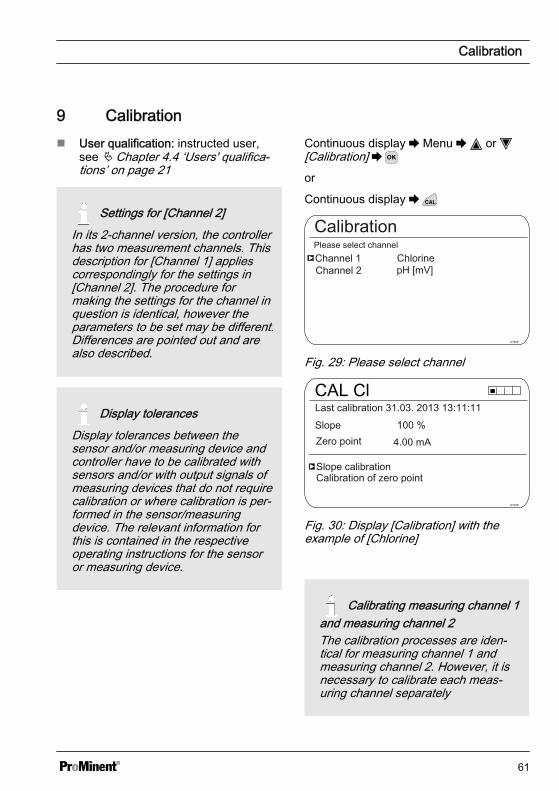
Channel 2Channel 1Please select channel
pH [mV]
CalibrationChlorine
Fig. 29: Please select channel
CAL Cl
A1039
Zero pointSlope
Slope calibrationCalibration of zero point
4.00 mA
Last calibration 31.03. 2013 13:11:11100 %
Fig. 30: Display [Calibration] with theexample of [Chlorine]
Calibrating measuring channel 1and measuring channel 2The calibration processes are iden‐tical for measuring channel 1 andmeasuring channel 2. However, it isnecessary to calibrate each meas‐uring channel separately
Calibration
61
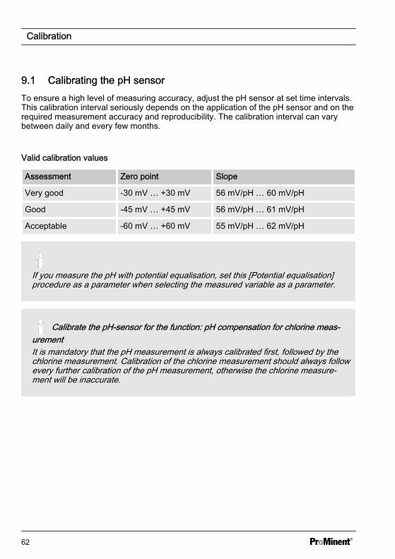
9.1 Calibrating the pH sensorTo ensure a high level of measuring accuracy, adjust the pH sensor at set time intervals.This calibration interval seriously depends on the application of the pH sensor and on therequired measurement accuracy and reproducibility. The calibration interval can varybetween daily and every few months.
Valid calibration values
Assessment Zero point Slope
Very good -30 mV … +30 mV 56 mV/pH … 60 mV/pH
Good -45 mV … +45 mV 56 mV/pH … 61 mV/pH
Acceptable -60 mV … +60 mV 55 mV/pH … 62 mV/pH
If you measure the pH with potential equalisation, set this [Potential equalisation]procedure as a parameter when selecting the measured variable as a parameter.
Calibrate the pH-sensor for the function: pH compensation for chlorine meas‐urementIt is mandatory that the pH measurement is always calibrated first, followed by thechlorine measurement. Calibration of the chlorine measurement should always followevery further calibration of the pH measurement, otherwise the chlorine measure‐ment will be inaccurate.
Calibration
62
Selecting the calibration process
Select the calibration process prior to ini‐tial calibration. This selection is saveduntil you select a new process.
n 2-point calibration: This is the recom‐mended calibration process becauseit evaluates the sensor characteristicdata: asymmetric potential, slope andresponse speed. 2 buffer solutionsare needed for 2-point calibration, e.g.pH 7 and pH 4 if subsequent meas‐urement is to be performed in anacidic medium or pH 7 and pH 10, ifsubsequent measurement is to beperformed in an alkaline medium. Thebuffer gap should be at least 2 pHunits.
n Samples (1-point) calibration: Thereare two options here. Samples (1-point) calibration is only recom‐mended with reservations. From timeto time check the sensor with 2-pointcalibration.– The pH sensor remains in the
sample medium and you shouldcalibrate a sample of the mediumto be measured against anexternal comparison measure‐ment. Perform the comparisonmeasurement using an electro‐chemical method. Deviations ofup to ± 0.5 pH units can occurusing the phenol red method(photometer).
– Calibration solely using a pH 7buffer. This only calibrates thezero point. The sensor is notchecked for an acceptable slope.
n Data input: With this calibrationmethod, using a comparison meas‐uring device, determine in advancethe characteristic data of the pHsensor (asymmetry and slope) atstandard temperature and enter this
data into the controller. The compara‐tive calibration should not be morethan one week old because the pHsensor's characteristic data changes ifthe data is saved for longer.
Calibration
63
Buffer temperature dependencies
Buffer temperatureAt temperatures that differ by 25 °C inthe process, adjust the pH of thebuffer solution by entering the refer‐ence values printed on the buffer sol‐ution bottle into the controller prior tocalibration.
Buffer temperature dependen‐ciesAn incorrectly entered buffer tempera‐ture can lead to incorrect calibration.Each buffer has different temperaturedependencies. You have variouschoices in terms of compensating forthese temperature dependencies, sothat the controller can correctlyprocess the buffer temperature.– Buffer temperature [Manual]:
Ensure that the buffer tempera‐ture is identical for both buffers.Enter the buffer temperature inthe [CAL Setup] menu item in thecontroller.
– Buffer temperature [Automatic]:Then immerse the temperaturesensor connected to the con‐troller together with the pH sensorinto the buffer. Wait for a suffi‐ciently long period of time untilthe pH and temperature sensorhave recorded the buffer tem‐perature.
– Buffer temperature [Off]: this set‐ting is not recommended. Pleaseuse another setting.
The sensor stability information displayedduring calibration, [acceptable], [good]and [very good], indicates to what extentthe sensor signal fluctuates during calibra‐tion. At the start of calibration, the waitingtime for stabilising of the measured valueis 30 seconds; during this waiting time,[Please wait!] flashes in the display. Youcannot continue with calibration duringthis waiting time.
If the pH sensor is cold, e.g. < 10 °C, thenthe pH sensor responds slowly and youhave to wait a few minutes until thesensor signal has stabilised.
The controller has no waiting time limit.You will see the actual [sensor voltage] inmV and can identify high fluctuations andassign influences to them, such as themovement of the sensor cable.
Calibration is impossible if the sensorsignal is very unsteady and the sensorsignal is disrupted by external influences,or if the sensor cable has a cable break orthe coaxial cable is damp. Rectify anyfault or cable break.
You can only continue with calibrationonce the signal bar has reached the[acceptable] range and remains there ormoves towards [good] or [very good].Changes to the signal within the ranges[acceptable], [good] and [very good] arepermitted.
The signal fluctuation width within theranges is specified as follows:
n first 30 seconds wait time, then evalu‐ation of the sensor signal– Acceptable: 0.5 mV/30s– Good: 0.3 mV/30s– Very good: 0.1mV/30s
Calibration
64

CAL pH
Asymmetry
Buffer 2:
A1019
Zero point
Slope% Slope
Accept with <CAL>
Buffer 1:
Calibr.param. for 25 °C
Fig. 31: Display of the calibration result
CAL pHAsymmetry in mV
Sensor quality
A1481Slope in mV/pH
acceptable
good
good
55 56 57 58 59 60 61 62
-60 -30 0 30 60
Fig. 32: Displayed after the key hasbeen pressed
9.1.1 Selecting the CalibrationProcess for pH
To calibrate the controller there are threeavailable calibration processes:
n 2-pointn Sample (1-point)n Data input
Selecting the calibration process
1. Continuous display
ð The Calibration menu is dis‐played, you may need to select[Channel 1] or [Channel 2],depending on the measuringchannel on which the pH meas‐urement is performed.
2. Press
CAL pH
Buffer manufacturer
Calibration process
A1025
Off
Buffer detection
2 point
requirement
Buffer value 1Buffer value 2
Buffer temperature
ProMinentpH 7pH 4
Fig. 33: Selecting the calibration process
ð The menu for selecting the cali‐bration process appears.
3. Use the arrow keys to select therequired menu item and press
ð The input window appears andyou can make the necessarysettings for your process
4. Use the arrow keys to select thecalibration process and press
5. Continue with
ð You can now start your chosencalibration process.
Calibration
65
9.1.2 2-point pH sensor calibration(CAL)
Correct sensor operation– Correct measuring and metering
is only possible if the sensor isworking perfectly
– Refer to the sensor's operatinginstructions
– 2-point calibration is strongly rec‐ommended and is preferable toother methods
– Remove the sensor from the in-line probe housing and re-fit it forcalibration. To do this, refer to theoperating instructions for your in-line probe housing
Determining buffer detectionThere are 2 methods of buffer detec‐tion with 2-point calibration.[Requirement]: you have to select 2buffers from the 4 possible buffer setsfor this. Adhere to the selected order,e.g. buffer value 1: pH 7 and buffervalue 2: pH 4 for calibration.– ProMinent® (pH 4; 7; 9; 10)– NBS/DIN 19266 (pH 1; 4; 7, ; 9)– DIN 19267 (pH 1;4; 7; 9; 13)– Merck + Riedel® (pH 2; 4; 7; 9;
12)The buffer sets vary with regard totheir pH values and temperaturedependencies configured in the con‐troller. The pH values for the differenttemperatures are also printed on thebuffer containers.[Manual]: enter the buffer value withthe associated temperature into thecontroller.– The pH values of the buffer solu‐
tion at temperatures that deviatefrom 25 °C are displayed in atable on the label of the bufferbottle.
Select the buffer you require.
Calibration
66
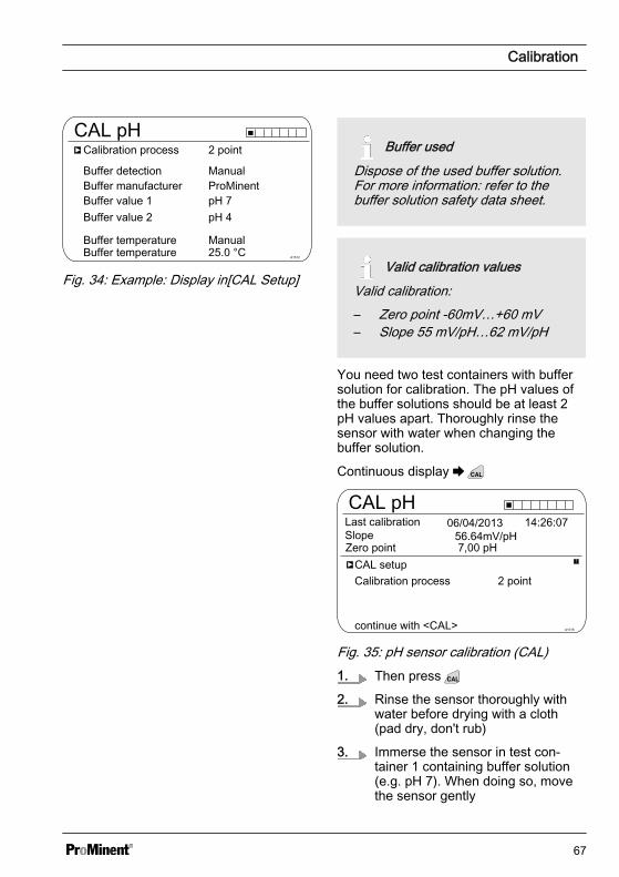
CAL pH
Buffer manufacturer
Calibration process
A1512
Manual
Buffer detection
2 point
Manual
Buffer value 1Buffer value 2
Buffer temperature
ProMinentpH 7pH 4
Buffer temperature 25.0 °C
Fig. 34: Example: Display in[CAL Setup]
Buffer usedDispose of the used buffer solution.For more information: refer to thebuffer solution safety data sheet.
Valid calibration valuesValid calibration:– Zero point -60mV…+60 mV– Slope 55 mV/pH…62 mV/pH
You need two test containers with buffersolution for calibration. The pH values ofthe buffer solutions should be at least 2pH values apart. Thoroughly rinse thesensor with water when changing thebuffer solution.
Continuous display
CAL pHLast calibration
A1016
Zero pointSlope
Calibration processCAL setup
continue with <CAL>
14:26:07
7,00 pH
2 point
56.64mV/pH 06/04/2013
Fig. 35: pH sensor calibration (CAL)1. Then press
2. Rinse the sensor thoroughly withwater before drying with a cloth(pad dry, don't rub)
3. Immerse the sensor in test con‐tainer 1 containing buffer solution(e.g. pH 7). When doing so, movethe sensor gently
Calibration
67

4. Continue with
ð Calibration is running .[Please wait!] flashes.
CAL pHSensor voltageSensor calibration in buffer 1
A1017
Buffer temperatureThe stability is:
acceptable good
continue with <CAL>
25.0 °C0.1 mV
very good
Fig. 36: Display of the sensor stability ach‐ieved5. The [acceptable / good / very good]
range is displayed
ð The black part of the horizontalbar indicates the rangedetected.
6. Continue with
7. [Buffer detection] e.g. [Manual]:Press and set the buffer valuefor buffer 1 to the value of the bufferyou are using with the four arrowkeys. Confirm the input of the valuewith
8. Remove the sensor from the buffersolution, rinse thoroughly in waterand then dry with a cloth (pad dry,don't rub!)
9. Continue with
10. Immerse the sensor in test con‐tainer 2 containing buffer solution(e.g. pH 4). When doing so, movethe sensor gently
11. Continue with
ð Calibration is running .[Please wait!] flashes.
CAL pHSensor voltageSensor calibration in buffer 2
A1018
Buffer temperatureThe stability is:
acceptable good
continue with <CAL>
25.0 °C173 mV
very good
Fig. 37: Display of the sensor stability ach‐ieved12. The [acceptable / good / very good]
range is displayed
ð The black part of the horizontalbar indicates the rangedetected.
13. Continue with
14. [Buffer detection] [Manual]: Press and set the buffer value for
buffer 2 to the value of the bufferyou are using with the four arrowkeys. Confirm input of the value bypressing
15. Continue with
CAL pH
Asymmetry
Buffer 2:
A1019
Zero point
Slope% Slope
Accept with <CAL>
Buffer 1:
Calibr.param. for 25 °C
Fig. 38: Display of the calibration result
Calibration
68
16.
Incorrect calibrationAn error message appearsshould the result of the calibra‐tion lie outside the specified tol‐erance limits. In this case thecurrent calibration will not beapplied.Check the prerequisites for cali‐bration and clear the error.Then repeat calibration.
Transfer the result of the calibrationinto the controller memory bypressing
ð The controller displays the con‐tinuous display again and oper‐ates with the results of the cali‐bration.
Calibration
69

9.1.3 pH sensor calibration (CAL) with an external sample (1-point)
Measuring and control behaviour of the controller during calibrationDuring calibration the actuating outputs are deactivated. Exception: a basic load or amanual control variable has been set. This remains active. The measured valueoutput [standard signal output mA] is frozen, corresponding to its settings in the mAoutput menu.When calibration/testing has been completed successfully, all of the error checksrelating to the measured value are restarted. The controller saves all the determineddata for zero point and slope upon a successful calibration.
NOTICE!
Poor sensor operation and fluctuating pH values during the processThe calibration method with an external sample has a number of disadvantagescompared with the buffer solution calibration method. If the pH value fluctuates sig‐nificantly during the process, then the pH value may change by a variable amount inthe period between sampling, sample measurement and entry of the pH value intothe controller. This could mean that the pH value entered into the controller does notcorrespond to the actual pH value in the process. Consequently the result is a lineardisplacement of the pH value across the entire measuring range.
If the pH sensor no longer reacts to changes in the pH value and only gives out aconstant uniform mV signal, this cannot be detected using the calibration methodwith an external sample. With the calibration method with two buffers (e.g. pH 7 andpH 4), this becomes apparent if the pH sensor does not detect any changes in thepH value.
The calibration method with an external sample should only be used with installa‐tions where there is poor access to the pH sensor and the identical or very uniformpH values are used in the process. In addition the pH sensor should be regularlyserviced or replaced.
Calibration
70

Correct sensor operation– Correct measuring, control and metering is only possible if the sensor is working
perfectly– Refer to the sensor's operating instructions
Valid calibration values
Evaluation Zero point Slope
Very good -30 mV … +30 mV 56 mV/pH … 60 mV/pH
Good -45 mV … +45 mV 56 mV/pH … 61 mV/pH
Acceptable -60 mV … +60 mV 55 mV/pH … 62 mV/pH
Continuous display
CAL pH
Calibration process
A1023
Zero pointSlope
Last calibration
CAL setup
continue with <CAL>
06/05/2013 14:26:07
Sample (1-point)Buffer temperature Manual
Fig. 39: pH sensor calibration (CAL)1. Continue with
2. Take a water sample at the in-line probe housing and, using a suitable method(measuring strips, hand measuring instrument), measure the pH value of thesample
Calibration
71
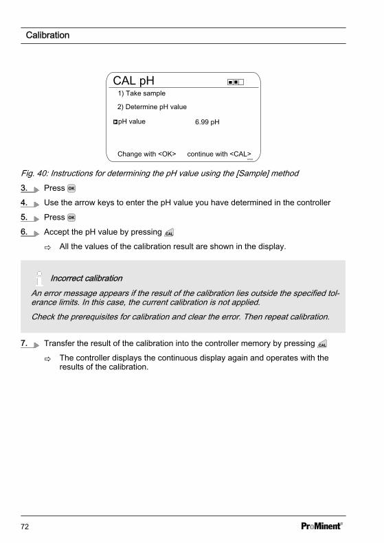
CAL pH
Change with <OK>A1022
2) Determine pH value
pH value
continue with <CAL>
1) Take sample
Fig. 40: Instructions for determining the pH value using the [Sample] method3. Press
4. Use the arrow keys to enter the pH value you have determined in the controller
5. Press
6. Accept the pH value by pressing
ð All the values of the calibration result are shown in the display.
Incorrect calibrationAn error message appears if the result of the calibration lies outside the specified tol‐erance limits. In this case, the current calibration is not applied.Check the prerequisites for calibration and clear the error. Then repeat calibration.
7. Transfer the result of the calibration into the controller memory by pressing
ð The controller displays the continuous display again and operates with theresults of the calibration.
Calibration
72
9.1.4 Calibration of the pH Sensor (CAL) by [Data Input]
Data inputUsing the [Calibration of the pH sensor (CAL) by data input] calibration method, thesensor's known data is entered into the controller. Calibration by data input is only asaccurate and reliable as the method with which the data was determined.The sensor data must have been determined in real-time. The more up-to-date thesensor data is, the more reliable is this calibration method.
Correct sensor operation– Correct measuring and metering is only possible if the sensor is working per‐
fectly– Refer to the sensor's operating instructions
Measuring and control behaviour of the controller during calibrationDuring calibration the actuating outputs are deactivated. Exception: a basic load or amanual control variable has been set. This remains active. The measured valueoutput [standard signal output mA] is frozen, corresponding to its settings in the mAoutput menu.When calibration/testing has been completed successfully, all of the error checksrelating to the measured value are restarted. The controller saves all the determineddata for zero point and slope upon a successful calibration.
Calibration
73

Valid calibration values
Evaluation Zero point Slope
Very good -30 mV … +30 mV 56 mV/pH … 60 mV/pH
Good -45 mV … +45 mV 56 mV/pH … 60,5 mV/pH
Acceptable -60 mV … +60 mV 55 mV/pH … 62 mV/pH
Continuous display
CAL pH
Calibration process Data input
A1024
Zero pointSlope
Last calibration
CAL setup
continue with <CAL>
16:47:327,00 pH
59.16 mV/pH
06/05/2013
Fig. 41: pH sensor calibration (CAL)1. Continue with
CAL pH
6.88 pH
Slope at 25.0 °C
A1026
or
-58.07 mV/pH
continue with <CAL>
Asymmetry at 25.0 °C
Zero point at 25.0 °C
-6.4 mV
Fig. 42: Selection of the settable parameters2. Use the arrow keys to select the required menu item and press
ð The entry window appears.
3. Enter the values for your sensor using the arrow keys and press
4. Continue with
Calibration
74
Incorrect calibrationAn error message appears if the result of the calibration lies outside the specified tol‐erance limits. In this case, the current calibration is not applied.Check the prerequisites for calibration and clear the error. Then repeat calibration.
5. Transfer the result of the calibration into the controller memory by pressing
ð The controller displays the continuous display again and operates with theresults of the calibration.
Calibration
75

9.2 Calibrating the ORP Sensor
9.2.1 Selecting the calibrationprocess for ORP
Selecting the calibration process
There are two calibration processes avail‐able for calibrating the controller:
n 1-point (with buffer solution)n Data input
1. Continuous display
CAL ORP
Pot. equalisationCalibration process
A1027
No
0.0 mVOffsetLast calibration
CAL setup
13:26:1111/04/2013
continue with <CAL>
1 point
Fig. 43: [ORP] calibration menu
ð The calibration menu is dis‐played.
2. Use to select the Setup menu orstart calibration by pressing
Selecting the calibration process
3. [CAL Setup]: Press
ð The menu for selecting the cali‐bration process appears.
4. Using the arrow keys select therequired menu item[Calibration process] and press
ð The input window appears.
5. Use the arrow keys to select thecalibration process and press
6. Continue with
ð You can now start your chosencalibration process.
9.2.2 1-point calibration of ORPsensor (CAL)
Correct sensor operation– Correct measuring and metering
is only possible if the sensor isworking perfectly
– Refer to the sensor's operatinginstructions
– Remove the sensor from the in-line probe housing and re-fit it forcalibration. To do this, refer to theoperating instructions for your in-line probe housing
ORP sensor calibrationThe ORP sensor cannot be cali‐brated. Only an [OFFSET] deviationof magnitude ± 40 mV can be set andthus compensated. If the ORP sensordeviates by more than ± 40 mV fromthe reference value, then it must bechecked in accordance with therequirements of the sensor operatinginstructions.
Calibration
76
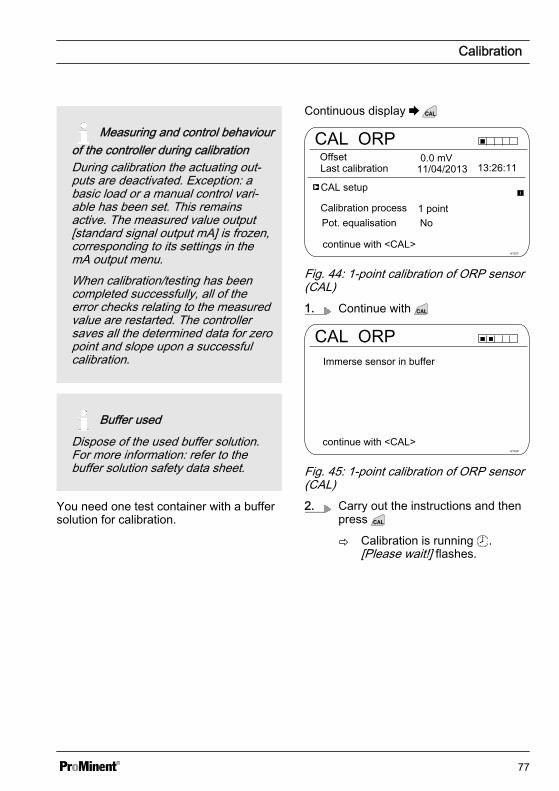
Measuring and control behaviourof the controller during calibrationDuring calibration the actuating out‐puts are deactivated. Exception: abasic load or a manual control vari‐able has been set. This remainsactive. The measured value output[standard signal output mA] is frozen,corresponding to its settings in themA output menu.When calibration/testing has beencompleted successfully, all of theerror checks relating to the measuredvalue are restarted. The controllersaves all the determined data for zeropoint and slope upon a successfulcalibration.
Buffer usedDispose of the used buffer solution.For more information: refer to thebuffer solution safety data sheet.
You need one test container with a buffersolution for calibration.
Continuous display
CAL ORP
Pot. equalisationCalibration process
A1027
No
0.0 mVOffsetLast calibration
CAL setup
13:26:1111/04/2013
continue with <CAL>
1 point
Fig. 44: 1-point calibration of ORP sensor(CAL)1. Continue with
CAL ORP
A1028
Immerse sensor in buffer
continue with <CAL>
Fig. 45: 1-point calibration of ORP sensor(CAL)2. Carry out the instructions and then
press
ð Calibration is running .[Please wait!] flashes.
Calibration
77

CAL ORPSensor voltageSensor calibration in buffer
A1029
The stability is:
acceptable good
continue with <CAL>
0.1 mV
very good
Fig. 46: Display of the sensor stability ach‐ieved3. The [acceptable / good / very good]
range is displayed
ð The black part of the horizontalbar indicates the rangedetected.
4. Continue with
CAL ORP
Offset
Buffer value
A1030Accept with <CAL>
165 mV
0.0 mV
Fig. 47: Adjusting the buffer value5. Press and use the four arrow
keys to adjust the mV value of thebuffer you are using
6. Press
7. Transfer the result of the calibrationinto the controller memory bypressing
ð The controller operates with thecalibration results.
9.2.3 Calibration data for ORPsensor (CAL)
Correct sensor operation– Correct measuring and metering
is only possible if the sensor isworking perfectly
– Refer to the sensor's operatinginstructions
– Remove the sensor from the in-line probe housing and re-fit it forcalibration. To do this, refer to theoperating instructions for your in-line probe housing
ORP sensor calibrationThe ORP sensor cannot be cali‐brated. Only an ‘OFFSET’ deviationof magnitude ± 40 mV can be set andthus compensated. If the ORP sensordeviates by more than ± 40 mV fromthe reference value, then it must bechecked in accordance with therequirements of the sensor operatinginstructions.
Calibration
78
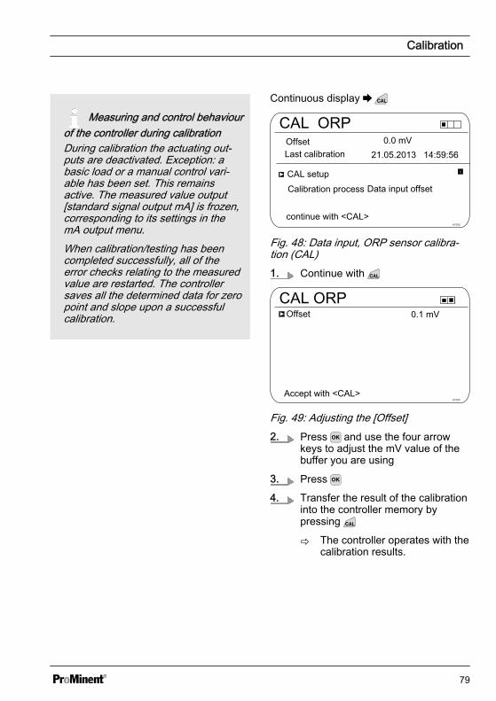
Measuring and control behaviourof the controller during calibrationDuring calibration the actuating out‐puts are deactivated. Exception: abasic load or a manual control vari‐able has been set. This remainsactive. The measured value output[standard signal output mA] is frozen,corresponding to its settings in themA output menu.When calibration/testing has beencompleted successfully, all of theerror checks relating to the measuredvalue are restarted. The controllersaves all the determined data for zeropoint and slope upon a successfulcalibration.
Continuous display
CAL ORP
CAL setup
A1032
Offset21.05.2013 14:59:56
continue with <CAL>
Calibration process
Last calibration0.0 mV
Data input offset
Fig. 48: Data input, ORP sensor calibra‐tion (CAL)1. Continue with
CAL ORPOffset
A1033Accept with <CAL>
0.1 mV
Fig. 49: Adjusting the [Offset]2. Press and use the four arrow
keys to adjust the mV value of thebuffer you are using
3. Press
4. Transfer the result of the calibrationinto the controller memory bypressing
ð The controller operates with thecalibration results.
Calibration
79

9.3 Calibrating the FluorideSensor
9.3.1 Selection of the calibrationprocess for fluoride
To calibrate the controller there are twoavailable calibration processes:
n 1 pointn 2 point
Calibration process selection
1. Continuous display
CAL F-
A1037
-59.16 mV/decSlope
1 ppm = 185.0 mV 16:51:18
Single point calibration
11:11:1111/11/2011
100 % 11/11/2011
Two point calibration
Fig. 50: Calibration menu [Fluoride]
ð The calibration menu is dis‐played.
2. Using the arrow keys select thedesired menu item. Press the key
ð You can now start the selectedcalibration process.
9.3.2 2-point fluoride sensor cali‐bration (CAL)
Correct sensor operation– Correct measuring and metering
is only possible if the sensor isworking perfectly
– Observe the sensor operatinginstructions
– The carrying out of a 2-point cali‐bration is strongly recommendedand is to be preferred to othermethods
– For calibration the sensor mustbe removed and refitted in the in-line probe housing. To do this,observe the operating instructionsof your in-line probe housing
Material required for calibration of fluoridesensors:
n Two test containers with calibratingsolution
Calibration
80

Measuring and control behaviourof the controller during calibrationDuring calibration the actuating out‐puts are deactivated. Exception: abasic load or a manual control vari‐able has been set. This remainsactive. The measured value output[standard signal output mA] is frozen,corresponding to its settings in themA output menu.When calibration/testing has beencompleted successfully, all of theerror checks relating to the measuredvalue are restarted. The controllersaves all the determined data for zeropoint and slope upon a successfulcalibration.
Used calibration solutionDispose of the used calibration solu‐tion. For more information: see cali‐bration solution safety data sheet.
Two test containers with a calibration sol‐ution are required for calibration. The fluo‐ride content of the calibrating solutionsshould be at least 0.5 ppm F- apart fromeach other. The sensor should be rinsedthoroughly with fluoride-free water whenchanging the calibrating solution.
1. Press the key in the continuousdisplay.
2. Using the arrow keys select[Two point calibration]
3. Then press
CAL F-Immerse sensor in buffer 1Two point calibration
A1038
Sensor value 2.50 ppm
Sensor voltage 161.4 mV
Start with <CAL>
Fig. 51: Fluoride sensor calibration (CAL)4. Immerse the sensor in test con‐
tainer 1 with calibration solution.When doing so gently move thesensor
5. Then press
ð [Calib. in progress] .
CAL F-Two point calibration
A1040
Sensor value 2.50 ppm
Change with <OK>
continue with <CAL>
Fig. 52: Fluoride sensor calibration (CAL)6. Then press to change the ppm
value or press to continue withthe calibration
7. Then press
Calibration
81
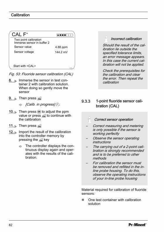
CAL F-
Immerse sensor in buffer 2Two point calibration
A1041
Sensor valueSensor voltage
Start with <CAL>
4.88 ppm144.2 mV
Fig. 53: Fluoride sensor calibration (CAL)8. Immerse the sensor in test con‐
tainer 2 with calibration solution.When doing so gently move thesensor
9. Then press
ð [Calib. in progress] .
10. Then press to adjust the ppmvalue or press to continue withthe calibration
11. Then press
12. Import the result of the calibrationinto the controller memory bypressing the key
ð The controller displays the con‐tinuous display again and oper‐ates with the results of the cali‐bration.
Incorrect calibrationShould the result of the cal‐ibration lie outside thespecified tolerance limits,an error message appears.In this case the current cal‐ibration will not be applied.Check the prerequisites forthe calibration and clearthe error. Then repeat thecalibration
9.3.3 1-point fluoride sensor cali‐bration (CAL)
Correct sensor operation– Correct measuring and metering
is only possible if the sensor isworking perfectly
– Observe the sensor operatinginstructions
– The carrying out of a 2-point cali‐bration is strongly recommendedand is to be preferred to othermethods
– For calibration the sensor mustbe removed and refitted in the in-line probe housing. To do this,observe the operating instructionsof your in-line probe housing
Material required for calibration of fluoridesensors:
n One test container with calibrationsolution
Calibration
82
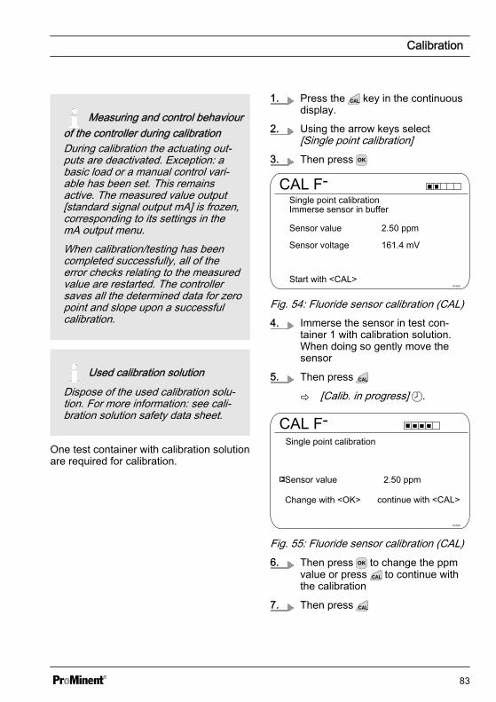
Measuring and control behaviourof the controller during calibrationDuring calibration the actuating out‐puts are deactivated. Exception: abasic load or a manual control vari‐able has been set. This remainsactive. The measured value output[standard signal output mA] is frozen,corresponding to its settings in themA output menu.When calibration/testing has beencompleted successfully, all of theerror checks relating to the measuredvalue are restarted. The controllersaves all the determined data for zeropoint and slope upon a successfulcalibration.
Used calibration solutionDispose of the used calibration solu‐tion. For more information: see cali‐bration solution safety data sheet.
One test container with calibration solutionare required for calibration.
1. Press the key in the continuousdisplay.
2. Using the arrow keys select[Single point calibration]
3. Then press
CAL F-Immerse sensor in bufferSingle point calibration
A1042
Sensor value 2.50 ppm
Sensor voltage 161.4 mV
Start with <CAL>
Fig. 54: Fluoride sensor calibration (CAL)4. Immerse the sensor in test con‐
tainer 1 with calibration solution.When doing so gently move thesensor
5. Then press
ð [Calib. in progress] .
CAL F-Single point calibration
A1043
Sensor value 2.50 ppm
Change with <OK>
continue with <CAL>
Fig. 55: Fluoride sensor calibration (CAL)6. Then press to change the ppm
value or press to continue withthe calibration
7. Then press
Calibration
83
8. Import the result of the calibrationinto the controller memory bypressing the key
ð The controller displays the con‐tinuous display again and oper‐ates with the results of the cali‐bration.
Incorrect calibrationShould the result of the cal‐ibration lie outside thespecified tolerance limits,an error message appears.In this case the current cal‐ibration will not be applied.Check the prerequisites forthe calibration and clearthe error. Then repeat thecalibration
9.4 Calibrating AmperometricSensors
Calibrating Amperometric Sen‐sorsThe process for calibrating ampero‐metric sensors is identical with allamperometric measured variables.The process for calibrating ampero‐metric measured variables isdescribed throughout based on themeasured variable chlorine [Cl]. Allother measured variables require thesame process as the measured vari‐able chlorine [Cl].The following measured variables canbe calibrated using the processdescribed here:– Chlorine– Chlorine dioxide– Bromine– Chlorite– Ozone– Peracetic acid (PES)– H2O2
Calibration combining pH andchlorineIt is imperative that you always cali‐brate the pH measurement first beforethe chlorine measurement. Thechlorine measurement always needsto be calibrated any further time thepH measurement is calibrated. Other‐wise the chlorine measurement will beinaccurate.
Calibration
84

9.4.1 Selecting the calibrationprocess for amperometricmeasured variables
There are two calibration processes avail‐able for calibrating the controller:
n Calibrating the slopen Calibrating the zero point
Selecting the calibration process
1. Continuous display
CAL Cl
A1039
Zero pointSlope
Slope calibrationCalibration of zero point
4.00 mA
Last calibration 31.03. 2013 13:11:11100 %
Fig. 56: [Chlorine] calibration menu
ð The calibration menu is dis‐played.
2. Use the arrow keys to select thechosen menu item. Press
ð You can now start your chosencalibration process.
9.4.2 Calibrating the slope
CAUTION!
Correct sensor operation / Run-inperiodDamage to the product or its sur‐roundings
– Correct measuring and meteringis only possible if the sensor isworking perfectly
– Please read the operating manualfor the sensor
– Please also read the operatingmanuals for the fittings and othercomponents used
– It is imperative that the run inperiods of the sensors areadhered to
– The run in periods should beallowed for when planning com‐missioning
– It may take an entire working dayto run in the sensor
Calibration
85
Measuring and control behaviourof the controller during calibrationDuring calibration the actuating out‐puts are deactivated. Exception: abasic load or a manual control vari‐able has been set. This remainsactive. The measured value output[standard signal output mA] is frozen,corresponding to its settings in themA output menu.When calibration/testing has beencompleted successfully, all of theerror checks relating to the measuredvalue are restarted. The controllersaves all the determined data for zeropoint and slope upon a successfulcalibration.
The measured value frozen at the start ofcalibration is suggested as a referencevalue. The reference value can be setusing the arrow keys. Calibration is onlypossible if the reference value is ≥ 2 % ofthe measuring range of the sensor.
NOTICE!
Prerequisites for correct calibration ofthe sensor slope– The reference method needed is
used, depending on the feedchemical used (e.g. DPD 1 forfree chlorine).
– The run-in period for the sensorhas been complied with; refer tothe operating instructions for thesensor.
– There is permitted and constantflow at the in-line probe housing
– There is temperature balancebetween the sensor and thesample water
– There is a constant pH value inthe permitted range
Material required for calibration ofamperometric sensors:
n A reference method suitable for themeasured variable in question
Calibration
86
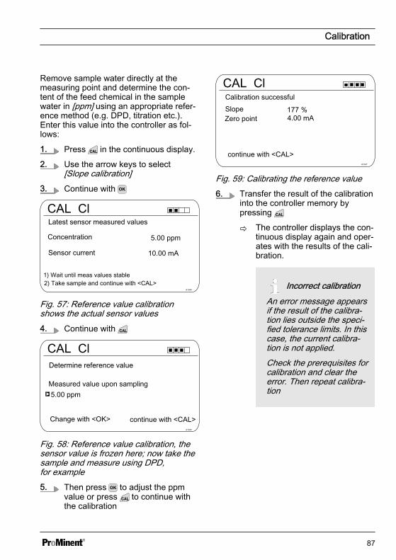
Remove sample water directly at themeasuring point and determine the con‐tent of the feed chemical in the samplewater in [ppm] using an appropriate refer‐ence method (e.g. DPD, titration etc.).Enter this value into the controller as fol‐lows:
1. Press in the continuous display.
2. Use the arrow keys to select[Slope calibration]
3. Continue with
CAL Cl
A1044
Concentration
Latest sensor measured values
2) Take sample and continue with <CAL>
Sensor current
1) Wait until meas values stable
Fig. 57: Reference value calibrationshows the actual sensor values4. Continue with
CAL Cl
A1045
Measured value upon sampling
Change with <OK>
Determine reference value
continue with <CAL>
Fig. 58: Reference value calibration, thesensor value is frozen here; now take thesample and measure using DPD,for example5. Then press to adjust the ppm
value or press to continue withthe calibration
CAL Cl
A1047
Calibration successfulSlope
continue with <CAL>
Zero point
Fig. 59: Calibrating the reference value6. Transfer the result of the calibration
into the controller memory bypressing
ð The controller displays the con‐tinuous display again and oper‐ates with the results of the cali‐bration.
Incorrect calibrationAn error message appearsif the result of the calibra‐tion lies outside the speci‐fied tolerance limits. In thiscase, the current calibra‐tion is not applied.Check the prerequisites forcalibration and clear theerror. Then repeat calibra‐tion
Calibration
87
Permitted calibration rangeThe permitted calibration range is20 ... 300% of the sensor's ratedvalue.Example of a shallow slope: Blockingof the sensor membrane leads to alow slope (low slope = low sensorsensitivity)Example of a steep slope: Surfactantsmake the sensor membrane morepermeable, leading to a steeper slope(steep slope = high sensor sensitivity)
9.4.3 Calibration of zero point
Necessity for calibrating the zeropointCalibration of the zero point is notgenerally necessary. A calibration ofthe zero point is only necessary if thesensor is operated at the lower limit ofthe measuring range or if the 0.5 ppmsensor version is used.
CAUTION!
Correct sensor operation / Run-inperiodDamage to the product or its sur‐roundings
– Correct measuring and meteringis only possible if the sensor isworking perfectly
– Please read the operating manualfor the sensor
– Please also read the operatingmanuals for the fittings and othercomponents used
– It is imperative that the run inperiods of the sensors areadhered to
– The run in periods should beallowed for when planning com‐missioning
– It may take a whole working dayto run-in the sensor
Calibration
88
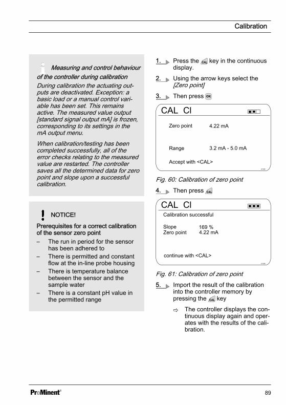
Measuring and control behaviourof the controller during calibrationDuring calibration the actuating out‐puts are deactivated. Exception: abasic load or a manual control vari‐able has been set. This remainsactive. The measured value output[standard signal output mA] is frozen,corresponding to its settings in themA output menu.When calibration/testing has beencompleted successfully, all of theerror checks relating to the measuredvalue are restarted. The controllersaves all the determined data for zeropoint and slope upon a successfulcalibration.
NOTICE!
Prerequisites for a correct calibrationof the sensor zero point– The run in period for the sensor
has been adhered to– There is permitted and constant
flow at the in-line probe housing– There is temperature balance
between the sensor and thesample water
– There is a constant pH value inthe permitted range
1. Press the key in the continuousdisplay.
2. Using the arrow keys select the[Zero point]
3. Then press
CAL Cl
A1046
Accept with <CAL>
Zero point
Range
Fig. 60: Calibration of zero point4. Then press
CAL Cl
A1048
continue with <CAL>
Zero pointSlope
Calibration successful
Fig. 61: Calibration of zero point5. Import the result of the calibration
into the controller memory bypressing the key
ð The controller displays the con‐tinuous display again and oper‐ates with the results of the cali‐bration.
Calibration
89
Incorrect calibrationShould the result of the cal‐ibration lie outside thespecified tolerance limits,an error message appears.In this case the current cal‐ibration will not be applied.Check the prerequisites forthe calibration and clearthe error. Then repeat thecalibration
9.5 Calibrating Oxygen SensorsSpecifying the calibration interval
The calibration interval depends heavilyon:
n the applicationn the installation location of the sensor
If you wish to calibrate a sensor for a spe‐cial application and/or a special installa‐tion location, then you can determine thecalibration intervals using the followingmethod. Check the sensor, e.g. onemonth after commissioning:
1. Remove the sensor from themedium
2. Clean the outside of the sensor witha damp cloth
3. Then gently dry the sensor mem‐brane for example using a papertowel
4. After 20 minutes measure theoxygen saturation index in the air
5. Protect the sensor from externalinfluences, such as sunlight andwind
ð Now decide depending on theexpected result:
Amperometric sensor: Calibratethe sensor if the measuredvalue is not 102 ± 2 %SAT.
If the value is within the set‐point range, then you canextend the calibration interval.Repeat this process monthlyand determine the optimum cal‐ibration interval for your appli‐cation from the results.
Calibration
90
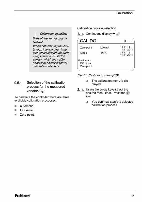
Calibration specifica‐tions of the sensor manu‐facturerWhen determining the cali‐bration interval, also takeinto consideration the oper‐ating instructions for thesensor, which may offeradditional and/or differentcalibration intervals.
9.5.1 Selection of the calibrationprocess for the measuredvariable O2
To calibrate the controller there are threeavailable calibration processes:
n automaticn DO valuen Zero point
Calibration process selection
1. Continuous display
CAL DO
A1049
Zero point
Slope
DO valueZero point
automatic
Fig. 62: Calibration menu [DO]
ð The calibration menu is dis‐played.
2. Using the arrow keys select thedesired menu item. Press the key
ð You can now start the selectedcalibration process.
Calibration
91

9.5.2 Selection of the calibrationprocess for the measuredvariable DO
CAUTION!
Correct sensor operation / Run-inperiodDamage to the product or its sur‐roundings
– Correct measuring and meteringis only possible if the sensor isworking perfectly
– Please read the operating manualfor the sensor
– Please also read the operatingmanuals for the fittings and othercomponents used
– It is imperative that the run inperiods of the sensors areadhered to
– The run in periods should beallowed for when planning com‐missioning
– It may take a whole working dayto run-in the sensor
Measuring and control behaviourof the controller during calibrationDuring calibration the actuating out‐puts are deactivated. Exception: abasic load or a manual control vari‐able has been set. This remainsactive. The measured value output[standard signal output mA] is frozen,corresponding to its settings in themA output menu.When calibration/testing has beencompleted successfully, all of theerror checks relating to the measuredvalue are restarted. The controllersaves all the determined data for zeropoint and slope upon a successfulcalibration.
Calibration
92
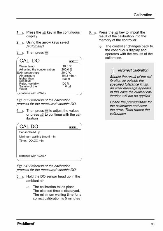
1. Press the key in the continuousdisplay.
2. Using the arrow keys select[automatic]
3. Then press
CAL DO
A1074
Air temperature
Water temp.
continue with <CAL>
Air pressure
Adjusting the concentration
higher than Sea levelRelat. humiditySalinity of the Water
Fig. 63: Selection of the calibrationprocess for the measured variable DO
4. Then press to adjust the valuesor press to continue with the cal‐ibration
CAL DO
A1075
Sensor head up
continue with <CAL>
Minimum waiting time 5 minTime: XX.XX min
Fig. 64: Selection of the calibrationprocess for the measured variable DO
5. Hold the DO sensor head up in theambient air.
ð The calibration takes place.The elapsed time is displayed.The minimum waiting time for acorrect calibration is 5 minutes
6. Press the key to import theresult of the calibration into thememory of the controller
ð The controller changes back tothe continuous display andoperates with the results of thecalibration.
Incorrect calibrationShould the result of the cal‐ibration lie outside thespecified tolerance limits,an error message appears.In this case the current cal‐ibration will not be applied.Check the prerequisites forthe calibration and clearthe error. Then repeat thecalibration
Calibration
93

9.5.3 Zero point calibration for themeasured variable DO
CAUTION!
Correct sensor operation / Run-inperiodDamage to the product or its sur‐roundings
– Correct measuring and meteringis only possible if the sensor isworking perfectly
– Please read the operating manualfor the sensor
– Please also read the operatingmanuals for the fittings and othercomponents used
– It is imperative that the run inperiods of the sensors areadhered to
– The run in periods should beallowed for when planning com‐missioning
– It may take a whole working dayto run-in the sensor
Measuring and control behaviourof the controller during calibrationDuring calibration the actuating out‐puts are deactivated. Exception: abasic load or a manual control vari‐able has been set. This remainsactive. The measured value output[standard signal output mA] is frozen,corresponding to its settings in themA output menu.When calibration/testing has beencompleted successfully, all of theerror checks relating to the measuredvalue are restarted. The controllersaves all the determined data for zeropoint and slope upon a successfulcalibration.
Calibration
94

1. Press the key in the continuousdisplay.
2. Using the arrow keys select[Zero point]
3. Then press
CAL DO
A1074
Air temperature
Water temp.
continue with <CAL>
Air pressure
Adjusting the concentration
higher than Sea levelRelat. humiditySalinity of the Water
Fig. 65: Zero point calibration for themeasured variable DO
4. Then press to adjust the valuesor press to continue with the cal‐ibration
CAL DO
A1079
Range
Accept with <CAL>
Zero point
Fig. 66: Zero point calibration for themeasured variable DO
5. Then press
CAL DO
A1080
Zero point
continue with <CAL>
Slope
Calibration successful
Fig. 67: Zero point calibration for themeasured variable DO
6. Press the key to import theresult of the calibration into thememory of the controller
ð The controller changes back tothe continuous display andoperates with the results of thecalibration.
The controller displays the con‐tinuous display again and oper‐ates with the results of the cali‐bration.
Incorrect calibrationShould the result of the cal‐ibration lie outside thespecified tolerance limits,an error message appears.In this case the current cal‐ibration will not be applied.Check the prerequisites forthe calibration and clearthe error. Then repeat thecalibration
Calibration
95
9.5.4 DO value calibration for themeasured variable DO
CAUTION!
Correct sensor operation / Run-inperiodDamage to the product or its sur‐roundings
– Correct measuring and meteringis only possible if the sensor isworking perfectly
– Please read the operating manualfor the sensor
– Please also read the operatingmanuals for the fittings and othercomponents used
– It is imperative that the run inperiods of the sensors areadhered to
– The run in periods should beallowed for when planning com‐missioning
– It may take a whole working dayto run-in the sensor
Measuring and control behaviourof the controller during calibrationDuring calibration the actuating out‐puts are deactivated. Exception: abasic load or a manual control vari‐able has been set. This remainsactive. The measured value output[standard signal output mA] is frozen,corresponding to its settings in themA output menu.When calibration/testing has beencompleted successfully, all of theerror checks relating to the measuredvalue are restarted. The controllersaves all the determined data for zeropoint and slope upon a successfulcalibration.
Calibration
96
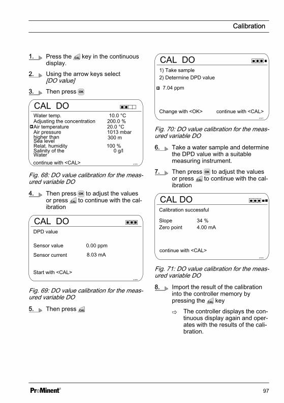
1. Press the key in the continuousdisplay.
2. Using the arrow keys select[DO value]
3. Then press
CAL DO
A1074
Air temperature
Water temp.
continue with <CAL>
Air pressure
Adjusting the concentration
higher than Sea levelRelat. humiditySalinity of the Water
Fig. 68: DO value calibration for the meas‐ured variable DO
4. Then press to adjust the valuesor press to continue with the cal‐ibration
CAL DO
A1076
DPD value
Start with <CAL>
Sensor value 0.00 ppm
Sensor current 8.03 mA
Fig. 69: DO value calibration for the meas‐ured variable DO
5. Then press
CAL DO
A1077
1) Take sample
Change with <OK>
7.04 ppm
continue with <CAL>
2) Determine DPD value
Fig. 70: DO value calibration for the meas‐ured variable DO
6. Take a water sample and determinethe DPD value with a suitablemeasuring instrument.
7. Then press to adjust the valuesor press to continue with the cal‐ibration
CAL DO
A1078
Calibration successful
Zero point
continue with <CAL>
Slope
Fig. 71: DO value calibration for the meas‐ured variable DO
8. Import the result of the calibrationinto the controller memory bypressing the key
ð The controller displays the con‐tinuous display again and oper‐ates with the results of the cali‐bration.
Calibration
97

Incorrect calibrationShould the result of the cal‐ibration lie outside thespecified tolerance limits,an error message appears.In this case the current cal‐ibration will not be applied.Check the prerequisites forthe calibration and clearthe error. Then repeat thecalibration
9.6 Measured value [mA gen‐eral] calibration
Measured value [mA general]calibrationThe measured value [mA general]cannot be calibrated, this menu itemis shown ‘greyed out’ and has nopurpose.
9.7 Calibrating conductivity
Measuring and control behaviourof the controller during calibrationDuring calibration the actuating out‐puts are deactivated. Exception: abasic load or a manual control vari‐able has been set. This remainsactive. The measured value output[standard signal output mA] is frozen,corresponding to its settings in themA output menu.When calibration/testing has beencompleted successfully, all of theerror checks relating to the measuredvalue are restarted. The controllersaves all the determined data for zeropoint and slope upon a successfulcalibration.
Calibration
98
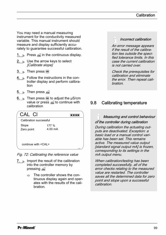
You may need a manual measuringinstrument for the conductivity measuredvariable. This manual instrument shouldmeasure and display sufficiently accu‐rately to guarantee successful calibration.
1. Press in the continuous display.
2. Use the arrow keys to select[Calibrate slope]
3. Then press
4. Follow the instructions in the con‐troller display and perform calibra‐tion
5. Then press
6. Then press to adjust the µS/cmvalue or press to continue withcalibration
CAL Cl
A1047
Calibration successfulSlope
continue with <CAL>
Zero point
Fig. 72: Calibrating the reference value7. Import the result of the calibration
into the controller memory bypressing
ð The controller shows the con‐tinuous display again and oper‐ates with the results of the cali‐bration.
Incorrect calibrationAn error message appearsif the result of the calibra‐tion lies outside the speci‐fied tolerance limits. In thiscase the current calibrationis not carried over.Check the prerequisites forcalibration and eliminatethe error. Then repeat cali‐bration.
9.8 Calibrating temperature
Measuring and control behaviourof the controller during calibrationDuring calibration the actuating out‐puts are deactivated. Exception: abasic load or a manual control vari‐able has been set. This remainsactive. The measured value output[standard signal output mA] is frozen,corresponding to its settings in themA output menu.When calibration/testing has beencompleted successfully, all of theerror checks relating to the measuredvalue are restarted. The controllersaves all the determined data for zeropoint and slope upon a successfulcalibration.
Calibration
99
You may need a manual measuringinstrument for the temperature measuredvariable. This manual instrument shouldmeasure and display sufficiently accu‐rately to guarantee successful calibration.
1. Press in the continuous display.
2. Then press
3. Follow the instructions in the con‐troller display and perform calibra‐tion
4. Then press
5. Then press to adjust the value orpress to continue with calibration
6. Import the result of the calibrationinto the controller memory bypressing
ð The controller shows the con‐tinuous display again and oper‐ates with the results of the cali‐bration.
Incorrect calibrationAn error message appearsif the result of the calibra‐tion lies outside the speci‐fied tolerance limits. In thiscase the current calibrationis not carried over.Check the prerequisites forcalibration and eliminatethe error. Then repeat cali‐bration.
Calibration
100

10 Setting the [Control]n User qualification: trained user, see Ä Chapter 4.4 ‘Users' qualifications’ on page 21Continuous display or [Control] [Control]
Settings for [Channel 2]In its 2-channel version, the controller has two measurement channels. This descrip‐tion for [Channel 1] applies correspondingly for the settings in [Channel 2]. The pro‐cedure for making the settings for the channel in question is identical, however theparameters to be set may be different. Differences are pointed out and are alsodescribed.
NOTICE!
Possible data lossIf you change measured variables in the [Measurement] menu, see Ä Chapter 8‘Setting measured variables’ on page 52, all settings in the [Measurement] and[Control] menus are reset to their factory settings (default values). You then have tore-enter the settings in the [Measurement] and [Control] menus. The operator isresponsible for the correct set-up of the controller.
Prerequisites for set up of the [Control]:The following settings are necessary for the [Control] set-up: If you have not yetmade the settings, do this now.– Specify the measured variables and all the necessary settings in the
[Measurement] menu, see Ä Chapter 8 ‘Setting measured variables’ on page 52– Specify all the actuators planned for the control task: You can find specifications
for the relevant electrical connections and settings in the following menus– [Pumps], see Ä Chapter 12 ‘Setting the [Pumps]’ on page 125– [Relays], see Ä Chapter 13 ‘Setting the [Relays]’ on page 128– [mA outputs], see Ä Chapter 15 ‘Setting the [mA outputs]’ on page 136
Actuators (regulator control elements) are, for example, metering pumps, solenoidvalves, motorised butterfly valves etc.
Setting the [Control]
101

Control
Disturbance variables
Channel 1 parameter set 1
metering lock
A0940
3.5
Parameter switch
Fig. 73: Continuous display or [Control] [Control]
pH [mV]TypeChannel 1 parameter set 1
Control time control
A0949
3.1.9
System responseSetpointxp=Add. Basic load
Ctrl output limitation
PID controlnormal7.00 pH1.54 pH0 %
100 %
Fig. 74: for the example of pH [mV]: Continuous display or [Control] [Control] or [Channel 1 parameter set 1] [Channel 1 parameter set 1]
Parameter level1
Function Parameter
[Channel 1parameter set 1]
[Type] none
P-control
PI control
PI control
[System response] Normal
Manual
With dead zone
[Setpoint] The adjustable range of the setpoint is speci‐fied by the device.
Setting the [Control]
102
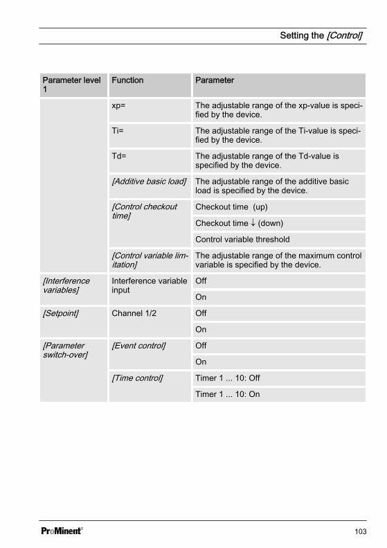
Parameter level1
Function Parameter
xp= The adjustable range of the xp-value is speci‐fied by the device.
Ti= The adjustable range of the Ti-value is speci‐fied by the device.
Td= The adjustable range of the Td-value isspecified by the device.
[Additive basic load] The adjustable range of the additive basicload is specified by the device.
[Control checkouttime]
Checkout time (up)
Checkout time ¯ (down)
Control variable threshold
[Control variable lim‐itation]
The adjustable range of the maximum controlvariable is specified by the device.
[Interferencevariables]
Interference variableinput
Off
On
[Setpoint] Channel 1/2 Off
On
[Parameterswitch-over]
[Event control] Off
On
[Time control] Timer 1 ... 10: Off
Timer 1 ... 10: On
Setting the [Control]
103
Each controller can be configured as a 1-way or 2-way controller. Two parametersets are available for each controller. The2nd parameter set is activated if the digitalinput 2 is set as the[Control parameter switch-over]. In thiscase [Parameter set 2] can be configuredin the menu.
When connecting the actuator, ensurethat the actuator which increases themeasured value is connected to the corre‐sponding output[Increase measured value], and theactuator which decreases the measuredvalue is connected to the output[Decrease measured value], seeÄ Chapter 6.3 ‘Electrical installation’on page 31.
Example: A medium with an actual valuepH 3 is to be have its pH increased to thesetpoint pH 7 using a sodium hydroxidesolution (pH >14). Therefore connect theactuator to the control output[Increase measured value].
Setting the [Control]
104

Direction of action of the [Control], 2- or 1-way
You can vary the [Control] based on various features.
Function: A 2-way [Control] operates in two possible directions (Increase AND decreasemeasured value).
Application: In a neutralisation process in an industrial waste water system, acidic oralkaline waste water is produced alternately. Before the water can be fed into the sew‐erage system, the pH value should, for example, be set to a value between pH 6.8 and7.5. A 2-way controller with two metering pumps for metering acid and alkali is used forthis purpose. The pH value can be both decreased or increased to come within the nec‐essary setpoint range.
Mea
sure
d va
lue
Setpoint
Con
trol v
aria
ble
Negative deviation
Negative Control variable
Time
Time
Positive Control variable
Positive deviation
A1471
Fig. 75: Control type two-way PID. Control characteristic without dead zone
Setting the [Control]
105

Mea
sure
d va
lue
Setp
oint
Con
trol o
utpu
t
Negative
Negative control output
Positive control output
Upper Setpoint (pH 7.3)
Lower Setpoint (pH 6.7)
Deadzone No control takes‘s place here
Time
Time
A1475
Positive Deviationto the setpoint
Deviationto the setpoint
Fig. 76: Control type two-way PID, with dead zone
Setting the [Control]
106
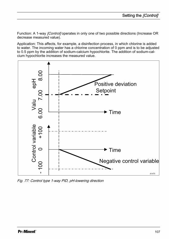
Function: A 1-way [Control] operates in only one of two possible directions (Increase ORdecrease measured value).
Application: This affects, for example, a disinfection process, in which chlorine is addedto water. The incoming water has a chlorine concentration of 0 ppm and is to be adjustedto 0.5 ppm by the addition of sodium-calcium hypochlorite. The addition of sodium-cal‐cium hypochlorite increases the measured value.
Valu
epH
Con
trol v
aria
ble
Positive deviation Setpoint
Negative control variable
Time
Time
A1470
Fig. 77: Control type 1-way PID, pH-lowering direction
Setting the [Control]
107

Valu
e pH
6.00
7
.00
8
.00
Setpoint
Con
trol v
aria
ble
-100
0
+1
00
Negative deviation
Positive control variable
Time
Time
A1472
Fig. 78: Control type 1-way PID, pH-increasing direction
Adjustable parameters in the [Control]menu
You have to make the following selectionin the Control menu:
10.1 Control parameter [Type]You set the controller type under themenu option [Type]. You can set the[Type] as [1-way] or [2-way].
P, PI, PID controllers are continuous con‐trollers. The control variables can take anyvalue in the control range from -100 % …+100 %.
P controller:
This controller type is used with an inte‐grating control path (e.g.[Batch Neutralisation]). If the control devi‐ation becomes small then the control(actuation) of the actuator becomes
Setting the [Control]
108
smaller (proportional relationship). If thesetpoint is nearly reached, then the con‐trol output is nearly 0 %. However the set‐point is never exactly reached. Conse‐quently a permanent control deviationresults. When stabilizing large changes,excess oscillations may occur.
PI controller:
This controller type is used with a non-integrating control path (e.g. flow neutrali‐sations). Here excess fluctuation must beavoided. No permanent control deviationmust occur. The setpoint must always beadhered to. A constant addition ofmetering chemicals is required. It is not amalfunction when the controller does notstop metering when the setpoint isreached.
PID controller:
This controller type has the properties of aPI controller. Due to the differentiatingcontrol part [D], it also offers a certainlevel of foresight and can react to forth‐coming changes. It is used when meas‐urement spikes occur in the measurementcurve and these must be quickly regulatedout.
10.2 Control parameter[System response]
You can set the system response of thecontroller under the menu option[System response].
Standard
The controller reacts with its P, PI or PIDsystem response as described inÄ Chapter 10.1 ‘Control parameter [Type]’on page 108.
[Standard] is the selection for [1-way ]controlled processes.
[Dead zone]
The [Dead zone] is defined by an upperand lower setpoint. The [dead zone] onlyoperates with a [2-way] [control], if anactuator is available for each direction.
The [dead zone] should have the effect ofpreventing the control path from starting tooscillate. If the measured value lies withinboth the setpoints, then no control of theactuators takes place. In this case even aPI/PID controller does not activate itsactuators. The [dead zone] is used with a[2-way] neutralisation.
10.3 Control parameter [Set‐point]
The setpoint specifies the target value forcontrol. The controller attempts to main‐tain the deviation between the setpointand the actual value (measured value) asclose to ‘0’ as possible.
Setting the [Control]
109

10.4 Control parameter [xp]The xp value is the controller amplification factor. The xp value relates to the measuringrange end of a controller and is entered as an absolute value. For pH for examplexp=1.5.
For measured variables such as chlorine, the sensor measuring range is selected. Thesensor measuring range corresponds to the measuring range end.
For pH, the measuring range end is 15.45. Here the default xp value is 1.54 (correspondsto ± 1.54 pH). The xp value states that for a deviation of ± 1.54 from the setpoint, thecontrol variable equals ± 100%. The smaller the xp value, the more ‘forcefully’ the con‐trol reacts, however the control also moves slightly into the over-control range.
Mea
sure
d va
lue
Setpoint
Con
trol v
aria
ble
A1473
Fig. 79: The smaller the xp value, the more "forcefully" the control reacts.
Setting the [Control]
110
10.5 Control parameter [Ti]The time [Ti] is the integral time of the I-controller (integral controller) in seconds.The time [Ti] defines the time integrationof the control deviation from the controlvariable. The smaller the time [Ti], thegreater the effect on the control variable.An infinitely long time [Ti] results in a pureproportional control.
10.6 Control parameter [Td]The time [Td] is the differentiation time ofthe D-controller (differential controller) inseconds. The D-controller reacts to therate of change of the measured value.
10.7 Control parameter [Add.Basic load]
[Add. Basic load] is the additive basicload. The additive basic load should bal‐ance out a continuous requirement forfeed chemical in order to maintain the set‐point.
The additive basic load can be set in therange -100 % … +100 %.
The additive basic load is added to thecontrol variable determined by the con‐troller and is effective in both control direc‐tions. E.g., if the control variable calcu‐lated by the controller equals
‘è y= -10 % and the add. basic loadequals +3 %, then the resulting controlvariable = Y= -10 % + (+3 %)= -7 %è y= 10 % and the add. basic loadequals +3 %, then the resulting controlvariable = Y= 10 % + (+3 %)= 13 %è y= 0% and the add. basic load equals+3%, then the resulting control variable =Y= 0 % + (+3 %)= 3 %’
10.8 Control parameter[Checkout time]
The [checkout time] should prevent over‐dosing as a result of a malfunction.
During the [checkout time] the control vari‐able is compared with an adjustable[threshold] (= control variable threshold).Depending on the control direction, youcan set different values for the[checkout times] [Checkout time “ up ] forincreasing and [Checkout time ” down] forreducing.
The thresholds depend on the concentra‐tion of the metered feed chemical. If thethreshold is exceeded, time recordingstarts [(checkout time)].If during the [checkout time] the variableagain falls below the threshold, then thetime is again reset to ‘0’ s.
If the control variable remains exceededfor longer than is permitted by the[checkout time], then control stops imme‐diately. This function (Control stop) resetsautomatically once the threshold is againundershot.
10.9 Control parameter [max.ctrl var.]
The [max. ctrl var.] specifies the maximumcontrol variable to be output. This makessense if an actuator is over-dimensionedand must not be opened to 100 %.
10.10 Interference variableSteadier control of flow processes using afeedforward control.
Setting the [Control]
111
Additive and multiplicative feedforwardcontrol
Alongside information relating to theactual measured variable, e.g. thechlorine concentration, the interferencevariable is a further source of informationfor the controller that makes it easier forthe controller to provide stable controlduring flow processes. During flow pro‐cesses, both the above parameterschange frequently within wide ranges. Ifone parameter variable is not known, thenit is impossible to achieve stable control ofthe other parameter variable. If processingof an interference variable is active, thenthe processing of the interference variableis signalled on the controller's continuousdisplay under[NAME OF INTERFERENCE VARIABLE]and [UNIT] with the letter [ Q]. Dependingon the configuration, an interference vari‐able can be effective for one or bothmeasuring channels
The signal source of the interference vari‐able can be supplied to the controller viaan analog signal or a frequency (incorpo‐rated in the basic design of the controller).Channel 2 should be equipped with equip‐ment package 2 (one main measured vari‐able, e.g. chlorine) or equipment package4 (2 main measured variables, e.g. pHand chlorine) to process an analog signal.
A frequency signal is connected to digitalinput 2 and an analog signal to mA input2. The interference variable can act onboth channels with accessory package 4,e.g.:
n mA input at channel 1: chlorine meas‐urement
n mV input at channel 2: pH measure‐ment
n Channel 2 analog input: flow signal
Applicational example of additive interfer‐ence variable
If the addition of a chemical is largely onlydependent on the flow (proportionaldependency), then the addition of an addi‐tive interference variable proportional tothe interference variable (flow), adds aproportion of the control variable to thecontrol variable of the setpoint controller(setpoint control, that is the comparison,setpoint: actual value). It is also possibleto completely switch off control of the set‐point and only provide flow-proportionalmetering. The measurement of the mainmeasured value can be used togetherwith the limit values as a monitoring func‐tion.
Applicational example:
You are to chlorinate drinking water. Therequired setpoint is 0.3 mg/l (ppm)chlorine. The volumetric flow of thedrinking water is measured with a flowmeter. The measuring signal of the flowmeter is routed to the controller via a 4 ...20 mA signal. A chlorine sensor CLE3continuously measures the chlorine. Thevolumetric flow alters within a wide flowrange from 0 ... 250 m³/h. The chlorineconcentration of 0.3 mg/l is achievedusing the proportionality between thewater flow and the added volume ofchlorine (the correct design of themetering pump according to the chlorineconcentration is a prerequisite). If thechlorine requirement were now toincrease, caused by a higher flow orgreater depletion (higher temperature,more germs), then an additional positivefraction of the setpoint control would beadded to the flow-proportional control vari‐able. If by contrast, too much chlorine is
Setting the [Control]
112

metered, caused by a too high proportion‐ality, then a negative control variablewould be issued and added to the flow-proportional control variable and theresulting control variable would fall.
Set the following in the controller's menu:
[Menu], [Control], [Interference variable],[On], [Signal source] = [mA input 2][Effect]: [additive][Assignment]: [0…20 mA] or [4…20 mA][Nominal value]: enter the maximumexpected analog current here, e.g. 18 mA
Setting the [Control]
113
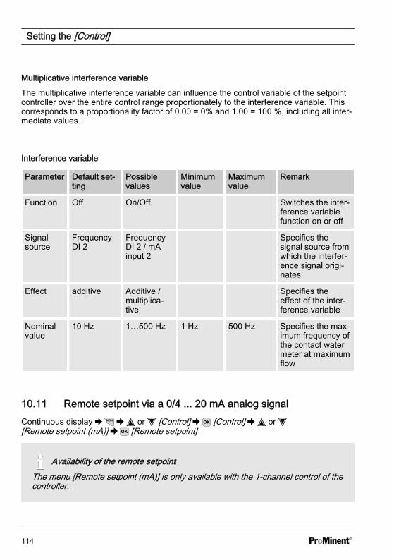
Multiplicative interference variable
The multiplicative interference variable can influence the control variable of the setpointcontroller over the entire control range proportionately to the interference variable. Thiscorresponds to a proportionality factor of 0.00 = 0% and 1.00 = 100 %, including all inter‐mediate values.
Interference variable
Parameter Default set‐ting
Possiblevalues
Minimumvalue
Maximumvalue
Remark
Function Off On/Off Switches the inter‐ference variablefunction on or off
Signalsource
FrequencyDI 2
FrequencyDI 2 / mAinput 2
Specifies thesignal source fromwhich the interfer‐ence signal origi‐nates
Effect additive Additive /multiplica‐tive
Specifies theeffect of the inter‐ference variable
Nominalvalue
10 Hz 1…500 Hz 1 Hz 500 Hz Specifies the max‐imum frequency ofthe contact watermeter at maximumflow
10.11 Remote setpoint via a 0/4 ... 20 mA analog signalContinuous display or [Control] [Control] or [Remote setpoint (mA)] [Remote setpoint]
Availability of the remote setpointThe menu [Remote setpoint (mA)] is only available with the 1-channel control of thecontroller.
Setting the [Control]
114
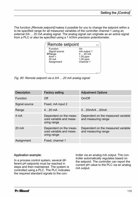
The function [Remote setpoint] makes it possible for you to change the setpoint within ato be specified range for all measured variables of the controller channel 1 using anexternal 0/4 ... 20 mA analog signal. The analog signal can originate as an active signalfrom a PLC or also be specified using a 1 kOhm precision potentiometer.
Remote setpointSignal sourceFunction
A1477
3.3.1
Range4mA = 20 mAAssignment
4 ... 20 mA1.00 ppm1.00 ppmChannel 1
mA output 1On
Fig. 80: Remote setpoint via a 0/4 ... 20 mA analog signal
Description Factory setting Adjustment Options
Function Off On/Off
Signal source Fixed, mA input 2
Range 4…20 mA 0…20mA/4…20mA
4 mA Dependent on the meas‐ured variable and meas‐uring range
Dependent on the measured variableand measuring range
20 mA Dependent on the meas‐ured variable and meas‐uring range
Dependent on the measured variableand measuring range
Assignment Fixed, channel 1
Application example:
In a process control system, several dif‐ferent pH setpoints must be reached insteps and then maintained. The system iscontrolled using a PLC. The PLC indicatesthe required standard signals to the con‐
troller via an analog mA output. The con‐troller automatically regulates based onthe setpoint. The controller can report thecurrent pH value to the PLC via an analogmA output.
Setting the [Control]
115
Required controller configura‐tion:You require package 2 for channel 2.You can find the corresponding infor‐mation under Ä Chapter 3 ‘ID Code’on page 15The function is available for allchannel 1 measured variables.Channel 2 is used for processing theremote setpoint.
Electrical connectionThe 0/4 ... 20 mA analog signal speci‐fies the setpoint and is connected toterminals XE8 3 (-) and 4 (+) of theexpansion module.
10.12 [Parameter switch] viathe digital input or[Timer]
Continuous display or [Control] [Control] or [Parameter switch] [Parameter switch]An [Event controlled] or [Time controlled][Parameter switch] allows you to activatean external potential-free switching signalfor each alternative parameter set for all ofthe measured variables of channel 1 andchannel 2 of the controller. Alternativelyyou can activate this switchover in a timedependent manner using 10 [Timers]. Theexisting active signal is valid, either[Time controlled] or [Event controlled].If [Parameter switch] is activated, thenmenu 3.1 also includes the parameterisa‐tion option for the respective parameterset 2. The selection option within theparameter set is identical to parameter set1. If parameter set 2 is not active, thenparameter set 1 is automatically activated.
Setting the [Control]
116

Application example:
In a process control system, two differentpH setpoints with different control parame‐ters must be reached and maintained. Thesystem is controlled using a PLC. ThePLC indicates the required event signal tothe controller via a digital output. The con‐troller then switches from[Channel 1 parameter set 2] to[Channel 2 parameter set 2] and thenmaintains the relevant setpoint automati‐cally. [Parameter set 2] must always beactivated from 22:00 to 05:00 Monday toFriday irrespective of the PLC setting.This is a combination of [Event controlled]and [Time controlled] operation.
Electrical connectionThe external release signal can beprocessed from digital input 2 (ter‐minal XK1_3 and 4) or digital input 5(terminal XK3_3 and 4).
Setting the [Control]
117
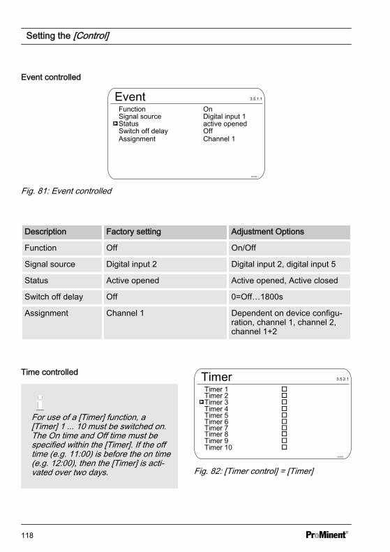
Event controlled
EventSignal sourceFunction
A1478
3.5.1.1
StatusSwitch off delayAssignment
active openedOffChannel 1
Digital input 1On
Fig. 81: Event controlled
Description Factory setting Adjustment Options
Function Off On/Off
Signal source Digital input 2 Digital input 2, digital input 5
Status Active opened Active opened, Active closed
Switch off delay Off 0=Off…1800s
Assignment Channel 1 Dependent on device configu‐ration, channel 1, channel 2,channel 1+2
Time controlled
For use of a [Timer] function, a[Timer] 1 ... 10 must be switched on.The On time and Off time must bespecified within the [Timer]. If the offtime (e.g. 11:00) is before the on time(e.g. 12:00), then the [Timer] is acti‐vated over two days.
TimerTimer 1
A1479
3.5.2.1
Timer 2Timer 3Timer 4Timer 5Timer 6Timer 7Timer 8Timer 9Timer 10
Fig. 82: [Timer control] = [Timer]
Setting the [Control]
118
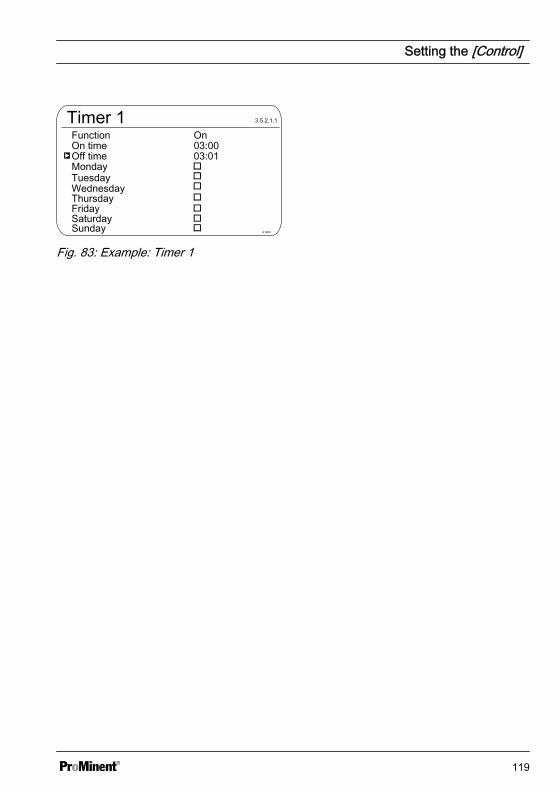
Timer 1On timeFunction
A1480
3.5.2.1.1
Off timeMondayTuesday
03:0103:00On
WednesdayThursdayFridaySaturdaySunday
Fig. 83: Example: Timer 1
Setting the [Control]
119

11 Setting the [Limit values]n User qualification: trained user, see Ä Chapter 4.4 ‘Users' qualifications’ on page 21Continuous display or [Limit values] [Limit values]
Settings for [Channel 2]In its 2-channel version, the controller has two measurement channels. This descrip‐tion for [Channel 1] applies correspondingly for the settings in [Channel 2]. The pro‐cedure for making the settings for the channel in question is identical, however theparameters to be set may be different. Differences are pointed out and are alsodescribed.
Limit valuesLimit value channel 1
A1011
4.1
Fig. 84: Setting the [Limit values]
11.1 Function of the limit valuesThe limit values are not related to the control setpoint.
The limit values are continuously compared with the measured value.
Setting the [Limit values]
120

The limit values are values that can be set within the measuring range of a measuredvariable. For each measuring channel a Limit [1] can be set for exceeding, i.e. the meas‐ured value is greater than the limit value and a Limit [2] can be set for undershooting, i.e.the measured value is less than the limit value. As the controller only has two limit valuerelays, there is an option of selecting a limit value ‘range’ . An upper and lower limit areset as a limit value ‘range’ . If the measured value is above or below the ‘range’ , then alimit value transgression exists.
If the limit is exceeded for longer than [the Control time lim. val. (∆t on)], then an errormessage will be triggered that has to be acknowledged and the alarm relay is deacti‐vated. If the [controller] is also set to [OFF] then the control process is stopped.
[Lower lim] means that the limit criterion has been transgressed by undershooting of thelower limit
[High limit] means that the limit criterion has been transgressed by exceeding of theupper limit.
The controller has the option of defining [Hysteresis limit values].[Hysteresis] works towards rectifying the limit transgression, i.e. if the [limit 1 upper] of,for example, pH 7.5 has been exceeded by a set hysteresis limit of, for example, pH0.20, then the criterion for limit transgression is redundant when the value drops belowthe lower limit of pH 7.3. The hysteresis behaviour for undershooting a [Low limit] func‐tions in a similar way (here the hysteresis value is added to the limit). In this way it is pos‐sible to forego an external relay in self-retaining mode.
If the limit is exceeded for longer than the [Delay period limits∆t on], then an acknowl‐edgeable fault message will be triggered and the alarm relay is deactivated. If the[controller] is also set to [OFF] then the control process is stopped.
Setting the [Limit values]
121
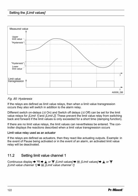
Measured value
Limit valuetransgression
Upperlimit value
"Hysteresis"
t
t
"Hysteresis“
Lowerlimit value
A0009_GB
Fig. 85: HysteresisIf the relays are defined as limit value relays, then when a limit value transgressionoccurs they also will switch in addition to the alarm relay.
Different switch on-delays (∆t On) and Switch off delays (∆t Off) can be set for the limitvalue relays for [Limit 1] and [Limit 2]. These prevent the limit value relay from switchingback and forward if the limit values is only exceeded for a short time (damping function).
If there are no limit value relays, the limit values can nevertheless be entered. The con‐troller displays the reactions described when a limit value transgression occurs
Limit value relay used as an actuator
If the relays are defined as actuators, then they react like actuating outputs. Example: inthe event of Pause being activated or in the event of an alarm, an activated limit valuerelay will be deactivated.
11.2 Setting limit value channel 1Continuous display or [Limit values] [Limit values] or [Limit value channel 1] [Limit value channel 1]
Setting the [Limit values]
122
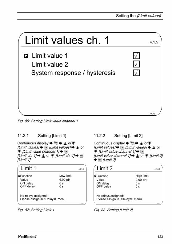
Limit values ch. 1Limit value 1
A1012
4.1.5
Limit value 2System response / hysteresis
Fig. 86: Setting Limit value channel 1
11.2.1 Setting [Limit 1]
Continuous display or[Limit values] [Limit values] or
[Limit value channel 1] [Limit ch. 1] or [Limit ch. 1] [Limit 1]
Limit 1Function Low limit
A1013
4.1.1.4
Value 6,00 pHON delayOFF delay
No relays assigned!Please assign in <Relays> menu.
Fig. 87: Setting Limit 1
11.2.2 Setting [Limit 2]
Continuous display or[Limit values] [Limit values] or
[Limit value channel 1] [Limit value channel 1] or [Limit 2] [Limit 2]
Limit 2Function High limit
A1166
4.1.3.1
Value 9.00 pHON delayOFF delay
No relays assigned!Please assign in <Relays> menu.
Fig. 88: Setting [Limit 2]
Setting the [Limit values]
123
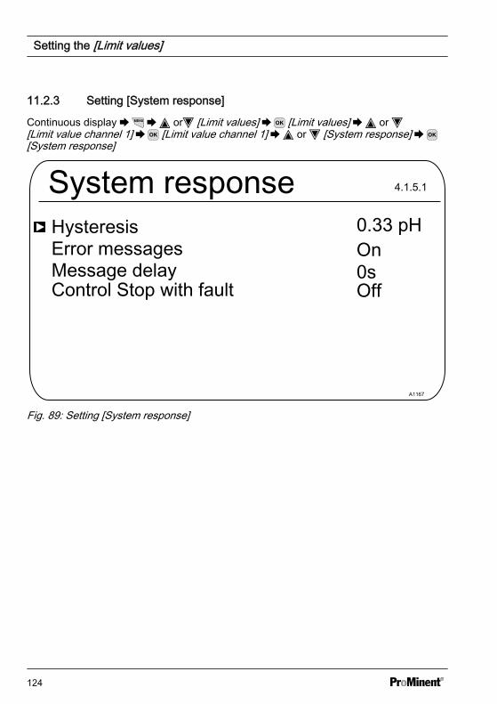
11.2.3 Setting [System response]
Continuous display or [Limit values] [Limit values] or [Limit value channel 1] [Limit value channel 1] or [System response] [System response]
System response
Error messages On
A1167
4.1.5.1
Hysteresis
Message delayControl Stop with fault Off
Fig. 89: Setting [System response]
Setting the [Limit values]
124
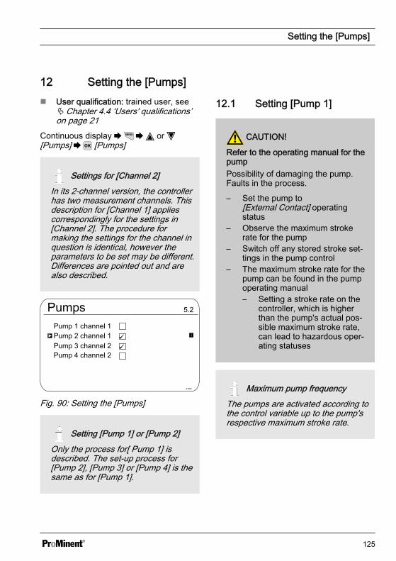
12 Setting the [Pumps]n User qualification: trained user, see
Ä Chapter 4.4 ‘Users' qualifications’on page 21
Continuous display or [Pumps] [Pumps]
Settings for [Channel 2]In its 2-channel version, the controllerhas two measurement channels. Thisdescription for [Channel 1] appliescorrespondingly for the settings in[Channel 2]. The procedure formaking the settings for the channel inquestion is identical, however theparameters to be set may be different.Differences are pointed out and arealso described.
Pumps
A1064
Pump 1 channel 1Pump 2 channel 1Pump 3 channel 2Pump 4 channel 2
Fig. 90: Setting the [Pumps]
Setting [Pump 1] or [Pump 2]Only the process for[ Pump 1] isdescribed. The set-up process for[Pump 2], [Pump 3] or [Pump 4] is thesame as for [Pump 1].
12.1 Setting [Pump 1]
CAUTION!
Refer to the operating manual for thepumpPossibility of damaging the pump.Faults in the process.
– Set the pump to[External Contact] operatingstatus
– Observe the maximum strokerate for the pump
– Switch off any stored stroke set‐tings in the pump control
– The maximum stroke rate for thepump can be found in the pumpoperating manual– Setting a stroke rate on the
controller, which is higherthan the pump's actual pos‐sible maximum stroke rate,can lead to hazardous oper‐ating statuses
Maximum pump frequencyThe pumps are activated according tothe control variable up to the pump'srespective maximum stroke rate.
Setting the [Pumps]
125
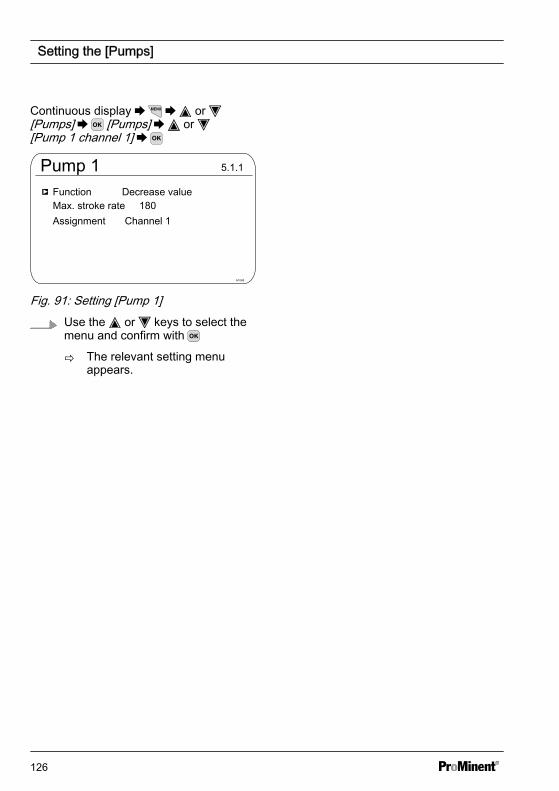
Continuous display or [Pumps] [Pumps] or [Pump 1 channel 1]
Pump 1
A1068
Function Decrease valueMax. stroke rate Assignment Channel 1
Fig. 91: Setting [Pump 1]Use the or keys to select themenu and confirm with
ð The relevant setting menuappears.
Setting the [Pumps]
126
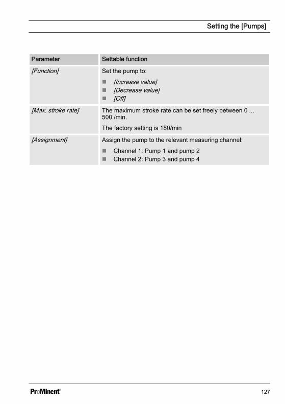
Parameter Settable function
[Function] Set the pump to:
n [Increase value]n [Decrease value]n [Off]
[Max. stroke rate] The maximum stroke rate can be set freely between 0 ...500 /min.
The factory setting is 180/min
[Assignment] Assign the pump to the relevant measuring channel:
n Channel 1: Pump 1 and pump 2n Channel 2: Pump 3 and pump 4
Setting the [Pumps]
127
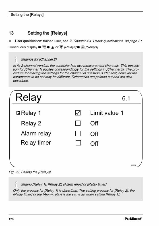
13 Setting the [Relays]n User qualification: trained user, see Ä Chapter 4.4 ‘Users' qualifications’ on page 21Continuous display or [Relays] [Relays]
Settings for [Channel 2]In its 2-channel version, the controller has two measurement channels. This descrip‐tion for [Channel 1] applies correspondingly for the settings in [Channel 2]. The pro‐cedure for making the settings for the channel in question is identical, however theparameters to be set may be different. Differences are pointed out and are alsodescribed.
Relay
A1069
Relay 1
Relay 2
6.1
Alarm relay
Limit value 1
Off
Relay timerOffOff
Fig. 92: Setting the [Relays]
Setting [Relay 1], [Relay 2], [Alarm relay] or [Relay timer]Only the process for [Relay 1] is described. The setting process for [Relay 2], the[Relay timer] or the [Alarm relay] is the same as when setting [Relay 1].
Setting the [Relays]
128
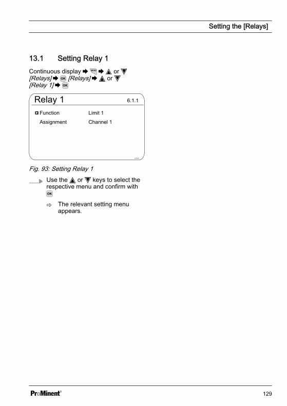
13.1 Setting Relay 1Continuous display or [Relays] [Relays] or [Relay 1]
Relay 1
A1070
Function
Assignment
6.1.1
Limit 1
Channel 1
Fig. 93: Setting Relay 1Use the or keys to select therespective menu and confirm with
ð The relevant setting menuappears.
Setting the [Relays]
129
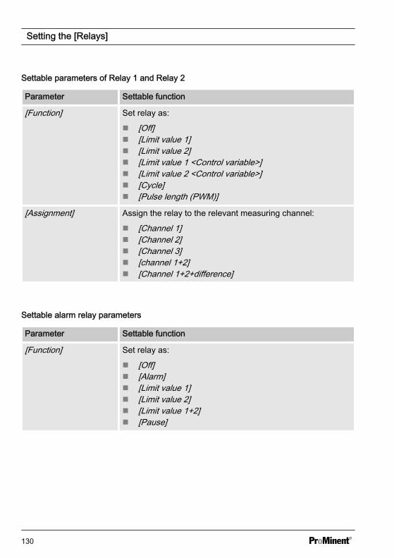
Settable parameters of Relay 1 and Relay 2
Parameter Settable function
[Function] Set relay as:
n [Off]n [Limit value 1]n [Limit value 2]n [Limit value 1 <Control variable>]n [Limit value 2 <Control variable>]n [Cycle]n [Pulse length (PWM)]
[Assignment] Assign the relay to the relevant measuring channel:
n [Channel 1]n [Channel 2]n [Channel 3]n [channel 1+2]n [Channel 1+2+difference]
Settable alarm relay parameters
Parameter Settable function
[Function] Set relay as:
n [Off]n [Alarm]n [Limit value 1]n [Limit value 2]n [Limit value 1+2]n [Pause]
Setting the [Relays]
130
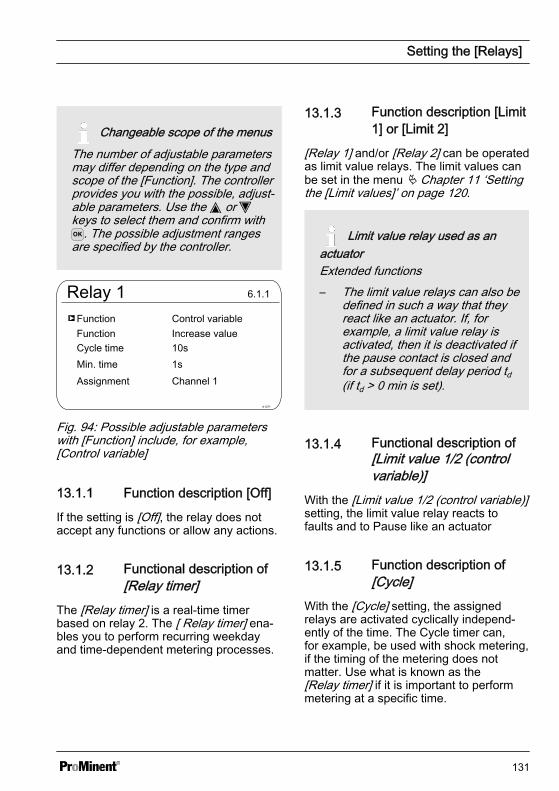
Changeable scope of the menusThe number of adjustable parametersmay differ depending on the type andscope of the [Function]. The controllerprovides you with the possible, adjust‐able parameters. Use the or keys to select them and confirm with
. The possible adjustment rangesare specified by the controller.
Relay 1
A1071
FunctionFunction
6.1.1
Control variable
Channel 1
Cycle timeMin. timeAssignment
Increase value10s1s
Fig. 94: Possible adjustable parameterswith [Function] include, for example,[Control variable]
13.1.1 Function description [Off]
If the setting is [Off], the relay does notaccept any functions or allow any actions.
13.1.2 Functional description of[Relay timer]
The [Relay timer] is a real-time timerbased on relay 2. The [ Relay timer] ena‐bles you to perform recurring weekdayand time-dependent metering processes.
13.1.3 Function description [Limit1] or [Limit 2]
[Relay 1] and/or [Relay 2] can be operatedas limit value relays. The limit values canbe set in the menu Ä Chapter 11 ‘Settingthe [Limit values]’ on page 120.
Limit value relay used as anactuatorExtended functions– The limit value relays can also be
defined in such a way that theyreact like an actuator. If, forexample, a limit value relay isactivated, then it is deactivated ifthe pause contact is closed andfor a subsequent delay period td(if td > 0 min is set).
13.1.4 Functional description of[Limit value 1/2 (controlvariable)]
With the [Limit value 1/2 (control variable)]setting, the limit value relay reacts tofaults and to Pause like an actuator
13.1.5 Function description of[Cycle]
With the [Cycle] setting, the assignedrelays are activated cyclically independ‐ently of the time. The Cycle timer can,for example, be used with shock metering,if the timing of the metering does notmatter. Use what is known as the[Relay timer] if it is important to performmetering at a specific time.
Setting the [Relays]
131
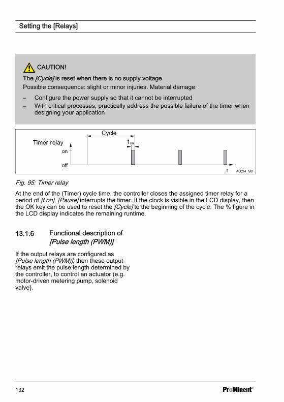
CAUTION!
The [Cycle] is reset when there is no supply voltagePossible consequence: slight or minor injuries. Material damage.
– Configure the power supply so that it cannot be interrupted– With critical processes, practically address the possible failure of the timer when
designing your application
CycleTimer relay
off
on
t
t on
A0024_GB
Fig. 95: Timer relayAt the end of the (Timer) cycle time, the controller closes the assigned timer relay for aperiod of [t on]. [Pause] interrupts the timer. If the clock is visible in the LCD display, thenthe OK key can be used to reset the [Cycle] to the beginning of the cycle. The % figure inthe LCD display indicates the remaining runtime.
13.1.6 Functional description of[Pulse length (PWM)]
If the output relays are configured as[Pulse length (PWM)], then these outputrelays emit the pulse length determined bythe controller, to control an actuator (e.g.motor-driven metering pump, solenoidvalve).
Setting the [Relays]
132

14 Setting [Digital inputs]n User qualification: trained user, see Ä Chapter 4.4 ‘Users' qualifications’ on page 21Continuous display or [Digital inputs] [Digital inputs]
Settings for [Channel 2]In its 2-channel version, the controller has two measurement channels. This descrip‐tion for [Channel 1] applies correspondingly for the settings in [Channel 2]. The pro‐cedure for making the settings for the channel in question is identical, however theparameters to be set may be different. Differences are pointed out and are alsodescribed.
Digital InputsDigital input 1
A0987
7.1
Digital input 2OffOff
Digital input 3 OffDigital input 4 OffDigital input 5 Off
Fig. 96: Setting digital inputs [Dig. inputs]
14.1 Setting [Digital input 1]Continuous display or [Digital inputs] [Digital Inputs] or [Digital input 1]
Setting [Digital inputs]
133
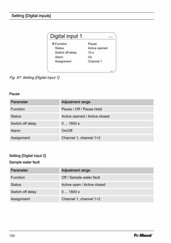
Digital input 1Function Pause
A0986
7.1.1
StatusSwitch off delay AlarmAssignment
Active opened10 sOnChannel 1
Fig. 97: Setting [Digital input 1]
Pause
Parameter Adjustment range
Function Pause / Off / Pause Hold
Status Active opened / Active closed
Switch off delay 0 ... 1800 s
Alarm On/Off
Assignment Channel 1, channel 1+2
Setting [Digital input 2]
Sample water fault
Parameter Adjustment range
Function Off / Sample water fault
Status Active open / Active closed
Switch off delay 0 ... 1800 s
Assignment Channel 1, channel 1+2
Setting [Digital inputs]
134
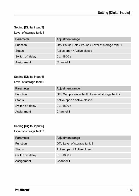
Setting [Digital input 3]
Level of storage tank 1
Parameter Adjustment range
Function Off / Pause Hold / Pause / Level of storage tank 1
Status Active open / Active closed
Switch off delay 0 ... 1800 s
Assignment Channel 1
Setting [Digital input 4]
Level of storage tank 2
Parameter Adjustment range
Function Off / Sample water fault / Level of storage tank 2
Status Active open / Active closed
Switch off delay 0 ... 1800 s
Assignment Channel 1
Setting [Digital input 5]
Level of storage tank 3
Parameter Adjustment range
Function Off / Level of storage tank 3
Status Active open / Active closed
Switch off delay 0 ... 1800 s
Assignment Channel 1
Setting [Digital inputs]
135
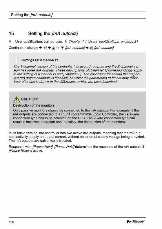
15 Setting the [mA outputs]n User qualification: trained user, Ä Chapter 4.4 ‘Users' qualifications’ on page 21Continuous display or [mA outputs] [mA outputs]
Settings for [Channel 2]The 1-channel version of the controller has two mA outputs and the 2-channel ver‐sion has three mA outputs. These descriptions of [Channel 1] correspondingly applyto the setting of [Channel 2] and [Channel 3]. The procedure for setting the respec‐tive mA output channels is identical, however the parameters to be set may differ.Your attention is drawn to the differences, which are also described.
CAUTION!
Destruction of the monitorsOnly passive monitors should be connected to the mA outputs. For example, if themA outputs are connected to a PLC Programmable Logic Controller, then a 4-wireconnection type has to be selected on the PLC. The 2-wire connection type canresult in incorrect operation and, possibly, the destruction of the monitors.
In its basic version, the controller has two active mA outputs, meaning that the mA out‐puts actively supply an output current, without an external supply voltage being provided.The mA outputs are galvanically isolated.
Response with [Pause Hold]: [Pause Hold] determines the response of the mA outputs if[Pause Hold] is active.
Setting the [mA outputs]
136
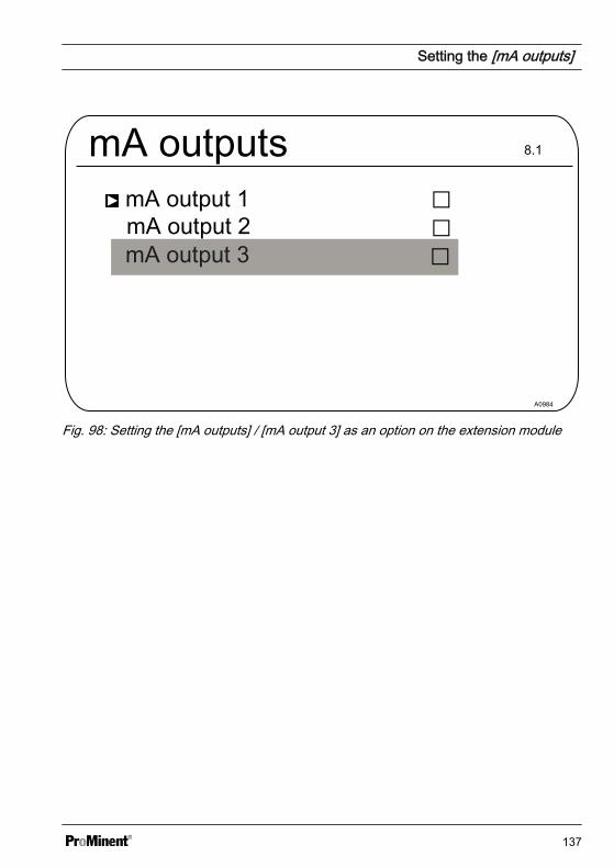
mA outputsmA output 1
A0984
8.1
mA output 2mA output 3
Fig. 98: Setting the [mA outputs] / [mA output 3] as an option on the extension module
Setting the [mA outputs]
137

15.1 Setting the [mA outputs]Continuous display or [mA outputs] [mA outputs] or [mA output 1] [Function] Set function
mA output 2 / mA output 3Menu items [mA output 2] and [mA output 3] have the same setting options as menuitem [mA output 1]. A separate description is not provided. [mA output 3] is locatedon the extension module and is only available if packages 2, 3 or 4 have beenselected with channel 2 in the identity code.
mA-output 1Function Measured value
A0985
Output range Current on error 0 mA 20 mA Damping HOLD reaction
0 ... 20 mA23 mA-1,45 pH15,45 pHhighHOLD
Assignment Channel 1
Fig. 99: Setting [mA output 1]
[Func‐tion ]
Adjustable value Explanation
[Function] [Off] The mA output has no function
[Measured value]
[Control variable]
[Correction value] Temperature
The mA output is held at the valid mA output value upstream of [Pause Hold].
Setting the [mA outputs]
138

The following adjustable parameters are available when selecting the [Measured value],[Control variable] and [Correction value] functions:
[Func‐tion ]
Adjustable value Adjustable ranges or counter values
[Meas‐uredvalue][Controlvariable][Correc‐tionvalue]
[Output range ] 0 ... 20 mA
Assignment to the required measuring range startand end value.
4 ... 20 mA
Assignment to the required measuring range startand end value.
[Error current] [Off]
23 mA
[0 mA] - 100 % ... 100 %
[20 mA] - 100 % ... 100 %
[Filtering] [high]
[medium]
[weak]
[Response with PauseHold]
[None]The mA output changes with the measured value
[Fixed]The mA output is set to a fixed mA output value,which is always issued at [Pause Hold]
[Hold]
Setting the [mA outputs]
139
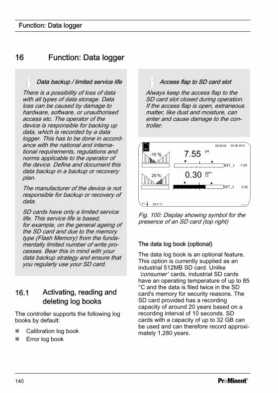
16 Function: Data logger
Data backup / limited service lifeThere is a possibility of loss of datawith all types of data storage. Dataloss can be caused by damage tohardware, software, or unauthorisedaccess etc. The operator of thedevice is responsible for backing updata, which is recorded by a datalogger. This has to be done in accord‐ance with the national and interna‐tional requirements, regulations andnorms applicable to the operator ofthe device. Define and document thisdata backup in a backup or recoveryplan.The manufacturer of the device is notresponsible for backup or recovery ofdata.SD cards have only a limited servicelife. This service life is based,for example, on the general ageing ofthe SD card and due to the memorytype (Flash Memory) from the funda‐mentally limited number of write pro‐cesses. Bear this in mind with yourdata backup strategy and ensure thatyou regularly use your SD card.
16.1 Activating, reading anddeleting log books
The controller supports the following logbooks by default:
n Calibration log bookn Error log book
Access flap to SD card slotAlways keep the access flap to theSD card slot closed during operation.If the access flap is open, extraneousmatter, like dust and moisture, canenter and cause damage to the con‐troller.
A1177
7.557.20
0.50
0.3025
-15
Fig. 100: Display showing symbol for thepresence of an SD card (top right)
The data log book (optional)
The data log book is an optional feature.This option is currently supplied as anindustrial 512MB SD card. Unlike‘consumer’ cards, industrial SD cardshave an operating temperature of up to 85°C and the data is filed twice in the SDcard's memory for security reasons. TheSD card provided has a recordingcapacity of around 20 years based on arecording interval of 10 seconds. SDcards with a capacity of up to 32 GB canbe used and can therefore record approxi‐mately 1,280 years.
Function: Data logger
140
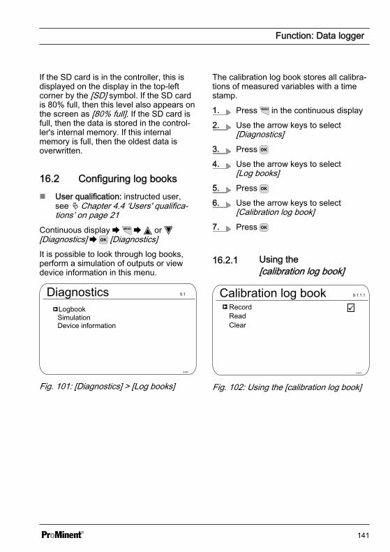
If the SD card is in the controller, this isdisplayed on the display in the top-leftcorner by the [SD] symbol. If the SD cardis 80% full, then this level also appears onthe screen as [80% full]. If the SD card isfull, then the data is stored in the control‐ler's internal memory. If this internalmemory is full, then the oldest data isoverwritten.
16.2 Configuring log booksn User qualification: instructed user,
see Ä Chapter 4.4 ‘Users' qualifica‐tions’ on page 21
Continuous display or [Diagnostics] [Diagnostics]It is possible to look through log books,perform a simulation of outputs or viewdevice information in this menu.
DiagnosticsLogbook
A0981
9.1
SimulationDevice information
Fig. 101: [Diagnostics] > [Log books]
The calibration log book stores all calibra‐tions of measured variables with a timestamp.
1. Press in the continuous display
2. Use the arrow keys to select[Diagnostics]
3. Press
4. Use the arrow keys to select[Log books]
5. Press
6. Use the arrow keys to select[Calibration log book]
7. Press
16.2.1 Using the[calibration log book]
Calibration log bookRecord
A1673
9.1.1.1
ReadClear
Fig. 102: Using the [calibration log book]
Function: Data logger
141
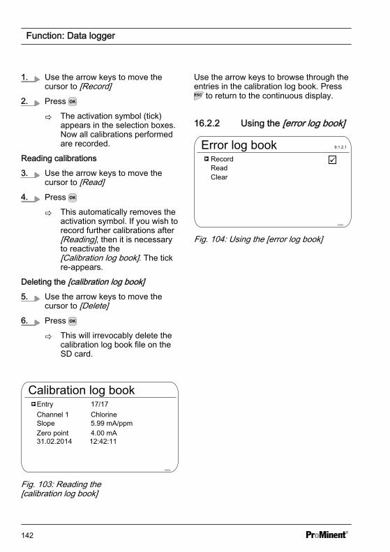
1. Use the arrow keys to move thecursor to [Record]
2. Press
ð The activation symbol (tick)appears in the selection boxes.Now all calibrations performedare recorded.
Reading calibrations
3. Use the arrow keys to move thecursor to [Read]
4. Press
ð This automatically removes theactivation symbol. If you wish torecord further calibrations after[Reading], then it is necessaryto reactivate the[Calibration log book]. The tickre-appears.
Deleting the [calibration log book]5. Use the arrow keys to move the
cursor to [Delete]6. Press
ð This will irrevocably delete thecalibration log book file on theSD card.
Calibration log bookEntry
A1674
Channel 1SlopeZero point
17/17Chlorine5.99 mA/ppm4.00 mA
Fig. 103: Reading the[calibration log book]
Use the arrow keys to browse through theentries in the calibration log book. Press
to return to the continuous display.
16.2.2 Using the [error log book]
Error log bookRecord
A1675
9.1.2.1
ReadClear
Fig. 104: Using the [error log book]
Function: Data logger
142

1. Use the arrow keys to select[Error log book]
2. Press
3. Use the arrow keys to move thecursor to [Record]
4. Press
ð The activation symbol (tick)appears in the selection boxes.Now all warnings and errormessages are recorded.
Reading messages
5. Use the arrow keys to move thecursor to [Read]
6. Press
ð This automatically removes theactivation symbol. If you wish torecord further errors after[Reading], then it is necessaryto reactivate the[Error log book]. The tick re-appears.
Deleting the [error log book]7. Use the arrow keys to move the
cursor to [Delete]8. Press
ð This will irrevocably delete theerror log book file on the SDcard.
Error log bookEntry
A1676
Warning 04 channel 2The measuring channel is not yet calibrated
32/32
Status coming
Fig. 105: Reading the [Error log book]Use the arrow keys to browse through theentries in the error log book. Press toreturn to the continuous display.
16.2.3 Using the [Data log book](optional)
The statuses of the digital inputsThe [Data log book] saves all meas‐ured values, correction variables, con‐trol variables and the status of thedigital inputs.
Data log bookRecord
A1677
9.1.3.1
ReadConfigure
Fig. 106: Configuring the [Data log book]First configure the [Data log book] beforeyou activate it. You can select which datais to be recorded. All data is selected bydefault. You can specify at what intervalthe data is to be saved. For example, if
Function: Data logger
143
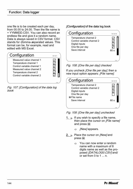
one file is to be created each per day,from 00.00 to 24.00. Then the file name is= YYMMDD.CSV. You can also record anendless file and give it a random name.Data is always saved in CSV format. CSVstands for Comma-separated values. Thisformat can be, for example, read andedited with MS Excel.
ConfigurationMeasured value channel 1
A1678
Temperature channel 1Control variable channel 1Measured value channel 2Temperature channel 2Control variable channel 2
9.1.4.1
Fig. 107: [Configuration] of the data logbook
[Configuration] of the data log book
Configuration
One file per day
A1679
Save interval
Digital inputs
Temperature channel 2Control variable channel 2
9.1.4.13
Fig. 108: [One file per day] checkedIf you uncheck [One file per day], then anew input option appears: [File name].
Configuration
One file per day
A1680
Save interval
Digital inputs
Temperature channel 2Control variable channel 2
9.1.4.13
File name
Fig. 109: [One file per day] unchecked1. If you wish to specify a file name,
then place the cursor on [File name]and press
ð [New] appears.
2. Place the cursor on [New] andpress
ð You can now enter a randomname with a maximum of 8digits name as well as the pro‐posed [DATALOG0.CSV] and/or set from 0 to 1 ... n.
Function: Data logger
144

The maximum file size is 2 GBThe maximum file size is 2 GB. TheSD card needs to be the same size.
Record
A1681
NewDATALOG0.CSV
9.1.3.4.1
Fig. 110: Check the file to write it to anexisting file, here [DATALOG0.CSV]3. If you wish to attached measured
data to an existing file, then checkthis file and the data will be writtento this file
If the SD card is removed, then data canbe recorded for a maximum of 24 hours inthe controller's internal memory with astorage interval of 10 seconds. Around sixtimes as long with an interval of 60 sec‐onds. When the SD card is re-insertedinto the controller, then the data from theinternal memory is backed up to the SDcard. This can take up to 20 minutes if 24hours of data has been recorded. Thegreen LED on the SD card reader flashesred/orange during this time.
Function: Data logger
145

17 [Diagnostics]n User qualification: instructed user,
see Ä Chapter 4.4 ‘Users' qualifica‐tions’ on page 21
Continuous display or [Diagnostics] [Diagnostics]It is possible to look through log books,perform a simulation of outputs or viewdevice information in this menu.
DiagnosticsLogbook
A0981
9.1
SimulationDevice information
Fig. 111: Diagnostics
17.1 Displaying [logbooks]Continuous display or [Diagnostics] [Diagnostics] or
[Calibration log book] [Calibration log book]
Log booksCalibration log book
A0982
9.1.1
Error log bookData log book
Fig. 112: Displaying [Log books]
17.1.1 Displaying the[Calibration Log Book]
The data on the sensor calibrations suc‐cessfully completed are stored in theinternal [Calibration log book]. Up to 30calibrations can be stored. Thereafter theoldest entry is overwritten with the mostrecent entry.
The following data is stored:
n Name of the measuring channeln Measured variablen Time of calibrationn Zero pointn Slope
Deleting entries inthe[Calibration log book]You can also delete entries in the Calibra‐tion log book. Deleting the entries doesnot affect the calibrations stored in thecontroller.
17.1.2 Reading the[Error Log Book]
The error message data is stored in the[Error log book]. Up to 30 error messagescan be stored. Thereafter the oldest entryis overwritten with the most recent entry.
[Diagnostics]
146

Error log bookEntry
A1161
9.1.2.1.1
Error
Status Goes
Channel 2The connection to the expansion module is faulty
Fig. 113: [Error log book]
Deleting entries in the [Error log book]You can also delete entries in the Errorlog book. Deleting the entries does notaffect the errors stored in the controller.
17.2 Displaying [simulation]Continuous display or [Diagnostics] [Diagnostics] or
[Simulation] [Simulation]
WARNING!
Uncontrolled responseCause: A controller operates uncon‐trolled in [Simulation] mode under fullload and thus so do the connectedactuators.
Possible consequence: Fatal or veryserious injuries
Measure: Never leave a controllerand its installed functional modulesunsupervised if the simulation func‐tion is active.
The [Simulation] menu item enables youto activate all outputs for test purposesduring commissioning. A simulated outputremains activated until you quite the[Simulation] menu item. It is also possibleto prime a peristaltic pump, for example,with [Simulation] mode. A
SimulationRelay 1
A0983
9.2.1
mA output 1mA output 1Pump 4Pump 3Pump 2Pump 1Alarm relayRelay 2
Off
OffOffOffOnOffOffOffOnOff
Fig. 114: Displaying simulation
17.3 Displaying[Device Information]
Continuous display or [Diagnostics] [Diagnostics] or
[Device information] [Device information]
Device infoIdentity Code
A1164
9.3.3
Softw. version: 01.00.00.00Srnr: 15082008
Module rev. 0100
Operating temperature 35.5 °C
Softw. version: 01.00.00.00Expansion module
Fig. 115: Device Information
[Diagnostics]
147
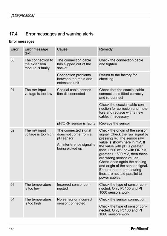
17.4 Error messages and warning alertsError messages
Error Error messagetext
Cause Remedy
88 The connection tothe extensionmodule is faulty
The connection cablehas slipped out of thesocket
Check the connection cableand tighten
Connection problemsbetween the main andextension unit
Return to the factory forchecking
01 The mV inputvoltage is too low
Coaxial cable connec‐tion disconnected
Check that the coaxial cableconnection is fitted correctlyand re-connect
Check the coaxial cable con‐nection for corrosion and mois‐ture and replace with a newcable, if necessary
pH/ORP sensor is faulty Replace the sensor
02 The mV inputvoltage is too high
The connected signaldoes not come from apH sensor
An interference signal isbeing picked up
Check the origin of the sensorsignal. Check the raw signal bypressing . The sensor rawvalue is shown here in mV. Ifthe value with pH is greaterthan ± 500 mV or with ORP isgreater ± 1500 mV, then theseare wrong sensor values.Check once again the cablingand origin of the sensor signal.Ensure that the measuringlines are not laid parallel topower cables.
03 The temperatureis too low
Incorrect sensor con‐nected
Check the type of sensor con‐nected. Only Pt 100 and Pt1000 sensors work
04 The temperatureis too high
No sensor or incorrectsensor connected
Check the sensor connection
Check the type of sensor con‐nected. Only Pt 100 and Pt1000 sensors work
[Diagnostics]
148

Error Error messagetext
Cause Remedy
05 There is a calibra‐tion error
With amperometric anal‐ysis (e.g. chlorine): thecalculated referencevalue deviates too muchfrom the real value orthe sensor value.
With amperometric analysis(e.g. chlorine): Check the cor‐rectness of the referencemethod, e.g. DPD1
With pH and ORP: thebuffers used differ fromthe nominal value, areoutdated or watereddown
With pH and ORP: replace thebuffer with new buffer
06 No sensor is fitted Coaxial cable connec‐tion disconnected
Check the correct connectionof the coaxial cable connection
No sensor is connected
07 Check themechanical stateof the sensor.Glass breakage ispossible.
Membrane glass broken Replace sensor
Check the reason for thebroken glass e.g. solids, toohigh a flow velocity
08 The checkout timewas infringed
In the [Control] menu,the set control variablehas exceeded thethreshold for a longertime than the checkouttime control variable
The control section needs alonger time to regulate itselfthan the selected checkouttime.
The control section needs agreater control variablethreshold to regulate itself thanthe selected one.
The metering chemical isempty or has a too low/high aconcentration
The metering line is discon‐nected or the point of injectionblocked.
09 The mA input cur‐rent is too high
The current is greaterthan the maximum per‐mitted current of 23 mA
Check the origin of the current.
[Diagnostics]
149

Error Error messagetext
Cause Remedy
Check the raw value in mA inthe Information menu bypressing . If the value is>23 mA, then it is not a correctsensor signal. Replace thesensor with a new sensor.
10 The mA input cur‐rent is too low
The power circuit is dis‐connected
Check the 2-wire connectionbetween the sensor/transmitterand controller and check theraw value in mA by pressing
. If the value is 0 mA, thenthe connection is disconnected
11 After elapse of thedelay period, alimit value errorstill exists.
The measured value liesabove the limit value fora period longer than theset delay period
Check whether the choice ofthe limit value matches theapplication and adjust the limitvalue if necessary.
Check whether the choice ofthe delay period matches theapplication and adjust thedelay period if necessary.
Check the design of theactuator. Is the actuatorselected too large?
Check the concentration of themetering chemical – is the con‐centration too high?
Check the control parameters.Does the control tend to over/undershoot?
12 There is a samplewater fault e.g. noflow
The in-line probe hou‐sing's sample water limitcontact e.g. DGMa wastriggered by the floatdropping.
Check the routing of thesample water line
Check the sample water dis‐charge point. Is it blocked?
Check if a sample water filter isfitted and clean it if necessary
[Diagnostics]
150
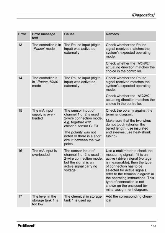
Error Error messagetext
Cause Remedy
13 The controller is in‘Pause’ mode
The Pause input (digitalinput) was activatedexternally
Check whether the Pausesignal received matches thesystem's expected operatingmode.
Check whether the ‘NO/NC’actuating direction matches thechoice in the controller.
14 The controller isin ‘ Pause (Hold)’mode
The Pause input (digitalinput) was activatedexternally
Check whether the Pausesignal received matches thesystem's expected operatingmode.
Check whether the ‘NO/NC’actuating direction matches thechoice in the controller.
15 The mA inputsupply is over‐loaded
The sensor input ofchannel 1 or 2 is used in2-wire connection mode,e.g. together withchlorine sensor CLE3.
The polarity was notnoted or there is a shortcircuit between the twopoles.
Check the polarity against theterminal diagram.
Make sure that the two wiresdo not touch (shorten thebared length, use insulatedend sleeves, use heat-shrinktubing)
16 The mA input isoverloaded
The sensor input ofchannel 1 or 2 is used in2-wire connection mode,but the signal is anactive signal carryingvoltage.
Use a multimeter to check themeasuring signal. If it is anactive / driven signal (voltageis measurable), then the typeof connection has to beselected for active signals,refer to the terminal diagram inthe operating instructions. Thistype of connection is notshown on the enclosed ter‐minal assignment diagram.
17 The level in thestorage tank 1 istoo low
The chemical in storagetank 1 is used up
Add the corresponding chem‐ical
[Diagnostics]
151

Error Error messagetext
Cause Remedy
18 The level instorage tank 2 istoo low
The chemical in storagetank 2 is used up
Add the corresponding chem‐ical
19 The level instorage tank 3 istoo low
The chemical in storagetank 3 is used up
Add the corresponding chem‐ical
99 There is a systemerror
System componentshave failed
Return the controller to themanufacturer for inspection
[Diagnostics]
152

Warning alerts
Warning
Warning alert text Cause Remedy
01 The limit valuewas undershot
The measured value isbelow the limit value
Check whether the choice ofthe limit value matches theapplication and adjust if neces‐sary.
Check the design of theactuator: has too small anactuator been selected?
Check the concentration of thefeed chemical: is the concen‐tration too low?
Check the control parameters:does the control tend to over/undershoot?
02 The limit valuewas exceeded
The measured value isabove the limit value
Check whether the choice ofthe limit value matches theapplication and adjust if neces‐sary.
Check the design of theactuator: has too large anactuator been selected?
Check the concentration of themetering chemical – is the con‐centration too high?
Check the control parameters:does the control tend to over/undershoot?
03 The wash timerhas timed out.Maintenance isnecessary
The wash timer acti‐vates a relay.
The sensor is cleanedwith cleaning fluid.
A visual check may benecessary as per yourmaintenance schedule
Clean and check the sensor.
[Diagnostics]
153

Warning
Warning alert text Cause Remedy
04 The measuringchannel is not yetcalibrated
The sensor connectedto a measuring channelhas not yet been cali‐brated
Calibrate the sensor
71 The batteryneeds to bereplaced
The battery has aservice life of about 10years, but this can bereduced by environ‐mental factors
Replace the battery or informService
Battery BR 2032, Part No.732829
72 Check the time The time has changedwhen replacing the bat‐tery
Reset the time
73 The fan has afault
The internal fan is nolonger rotating
Please check to see whetheran object has become trappedin the impeller otherwise returnthe controller to the manufac‐turer for inspection
89 System warning1
There is a system error Return the controller to themanufacturer for inspection
[Diagnostics]
154
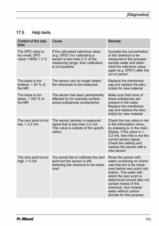
17.5 Help texts
Content of the helptexts
Cause Remedy
The DPD value istoo small, DPDvalue > MRS + 2 %
If the calculated reference value(e.g. DPD1) for calibrating asensor is less than 2 % of themeasuring range, then calibrationis not possible.
Increase the concentrationof the chemical to bemeasured in the process/sample water and deter‐mine the reference valueagain (e.g. DPD1) after therun-in period.
The slope is tooshallow, < 20 % ofthe MR
The sensor can no longer detectthe chemicals to be measured
Replace the membranecap and replace the elec‐trolyte for new material
The slope is toosteep, > 300 % ofthe MR
The sensor has been permanentlyaffected by for example surface-active substances (surfactants).
Make sure that none ofthese substances arepresent in the water.Replace the membranecap and replace the elec‐trolyte for new material
The zero point is toolow, < 3.2 mA
The sensor delivers a measuredsignal that is less than 3.2 mA.This value is outside of the specifi‐cation.
Check the raw value in mAin the Information menu,by pressing in the maindisplay. If the value is <3.2 mA, then this is not thecorrect sensor signal.Check the cabling andreplace the sensor with anew sensor.
The zero point is toohigh, > 5 mA
You would like to calibrate the zeropoint but the sensor is stilldetecting the chemical to be meas‐ured
Rinse the sensor withwater containing no chemi‐cals that are to be meas‐ured before zero point cali‐bration. The water withwhich the zero point isdetermined should also notcontain traces of thischemical. Use mineralwater without carbondioxide for this purpose.
[Diagnostics]
155
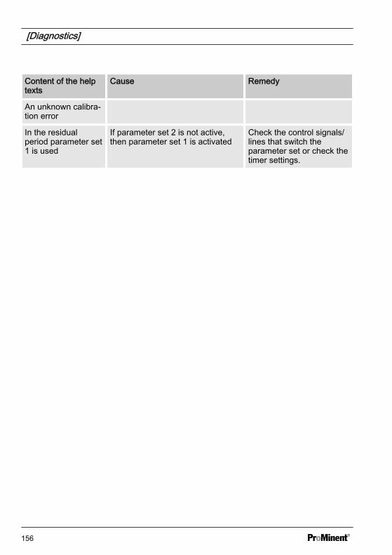
Content of the helptexts
Cause Remedy
An unknown calibra‐tion error
In the residualperiod parameter set1 is used
If parameter set 2 is not active,then parameter set 1 is activated
Check the control signals/lines that switch theparameter set or check thetimer settings.
[Diagnostics]
156
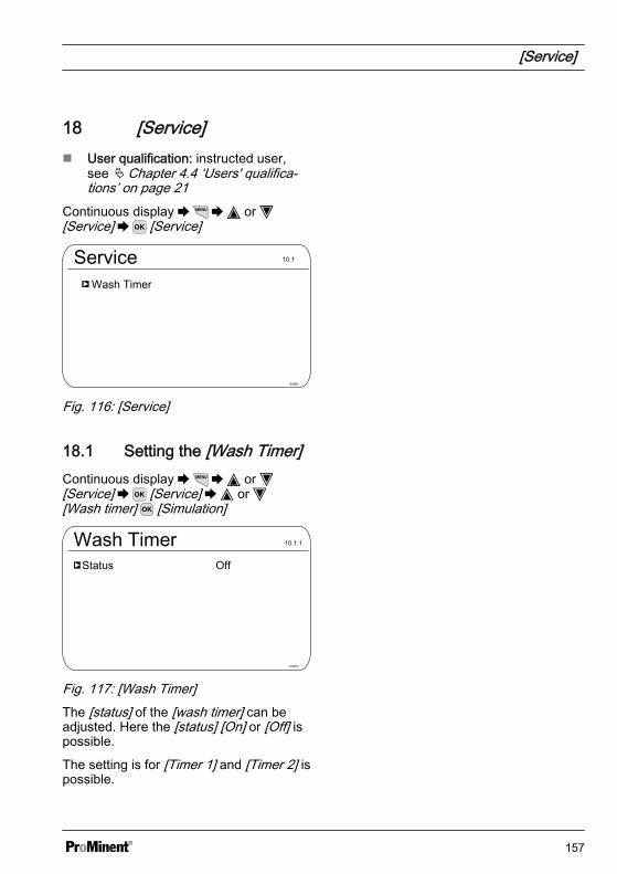
18 [Service] n User qualification: instructed user,
see Ä Chapter 4.4 ‘Users' qualifica‐tions’ on page 21
Continuous display or [Service] [Service]
ServiceWash Timer
A0980
10.1
Fig. 116: [Service]
18.1 Setting the [Wash Timer]Continuous display or [Service] [Service] or [Wash timer] [Simulation]
Wash Timer
A0977
10.1.1
Status Off
Fig. 117: [Wash Timer]The [status] of the [wash timer] can beadjusted. Here the [status] [On] or [Off] ispossible.
The setting is for [Timer 1] and [Timer 2] ispossible.
[Service]
157

19 Setting [Device setup]n User qualification: instructed user,
see Ä Chapter 4.4 ‘Users' qualifica‐tions’ on page 21
Continuous display or [Setup] [Device setup]
Device setupLanguage
A1073
11.1
Device configurationExtended configurationUpdateAccess codeReset
GERMAN
Fig. 118: Setting [Device setup]
Setting [Device setup]
158

19.1 Setting the [Language]Continuous display or [Setup] [Device setup] or [Language] [Language selection]
Available languages for output in the controller display*
German Greek Romanian
Arabic Hebrew Russian
Bulgarian Italian Swedish
Chinese Japanese Slovakian
Danish Korean Thai
English_GB Dutch Czech
English_US Norwegian Turkish
Finnish Polish Hungarian
French Portuguese
* Additional languages are planned.
Setting [Device setup]
159
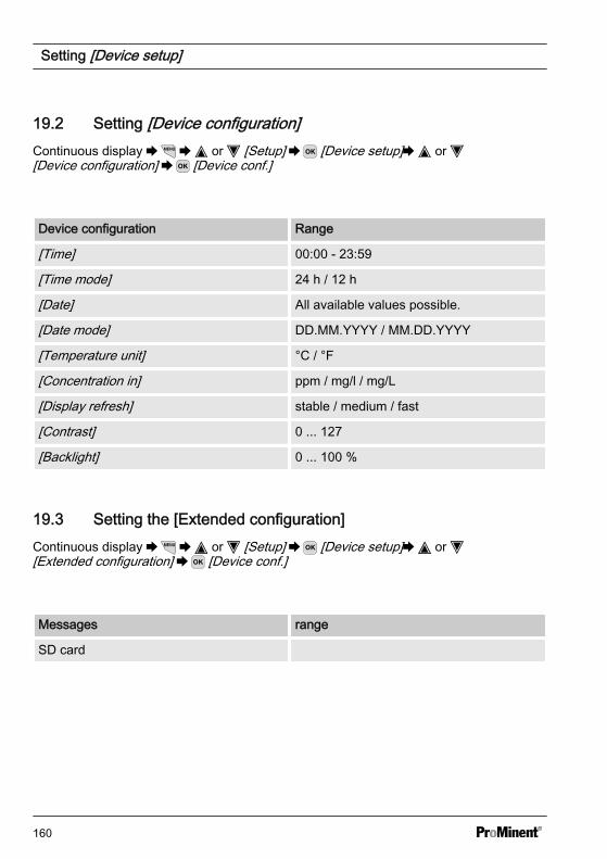
19.2 Setting [Device configuration]Continuous display or [Setup] [Device setup] or [Device configuration] [Device conf.]
Device configuration Range
[Time] 00:00 - 23:59
[Time mode] 24 h / 12 h
[Date] All available values possible.
[Date mode] DD.MM.YYYY / MM.DD.YYYY
[Temperature unit] °C / °F
[Concentration in] ppm / mg/l / mg/L
[Display refresh] stable / medium / fast
[Contrast] 0 ... 127
[Backlight] 0 ... 100 %
19.3 Setting the [Extended configuration]Continuous display or [Setup] [Device setup] or [Extended configuration] [Device conf.]
Messages range
SD card
Setting [Device setup]
160
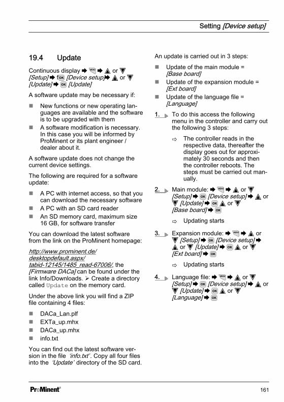
19.4 UpdateContinuous display or [Setup] f [Device setup] or [Update] [Update]A software update may be necessary if:
n New functions or new operating lan‐guages are available and the softwareis to be upgraded with them
n A software modification is necessary.In this case you will be informed byProMinent or its plant engineer /dealer about it.
A software update does not change thecurrent device settings.
The following are required for a softwareupdate:
n A PC with internet access, so that youcan download the necessary software
n A PC with an SD card readern An SD memory card, maximum size
16 GB, for software transfer
You can download the latest softwarefrom the link on the ProMinent homepage:
http://www.prominent.de/desktopdefault.aspx/tabid-12145/1485_read-67006/, the[Firmware DACa] can be found under thelink Info/Downloads. Ø Create a directorycalled Update on the memory card.
Under the above link you will find a ZIPfile containing 4 files:
n DACa_Lan.plfn EXTa_up.mhxn DACa_up.mhxn info.txt
You can find out the latest software ver‐sion in the file ‘info.txt’ . Copy all four filesinto the ‘Update’ directory of the SD card.
An update is carried out in 3 steps:
n Update of the main module =[Base board]
n Update of the expansion module =[Ext board]
n Update of the language file =[Language]
1. To do this access the followingmenu in the controller and carry outthe following 3 steps:
ð The controller reads in therespective data, thereafter thedisplay goes out for approxi‐mately 30 seconds and thenthe controller reboots. Thesteps must be carried out man‐ually.
2. Main module: or [Setup] [Device setup] or
[Update] or [Base board]
ð Updating starts
3. Expansion module: or [Setup] [Device setup] or [Update] or
[Ext board]
ð Updating starts
4. Language file: or [Setup] [Device setup] or
[Update] or [Language]
Setting [Device setup]
161

ð Updating starts
You can see the latest software ver‐sion of the controller upon boot-upand at the following point in the con‐troller menu[Menu] [Diagnostics] [Device information].
19.5 Setting the [Access code]Continuous display or [Setup] [Device setup] or [Access code] [Access code]
Access code
A1168
11.5.1
User 1User 2User 3User 4
Administrator SupervisorfreeUserfreefree
Fig. 119: Setting the [Access code]
Setting [Device setup]
162
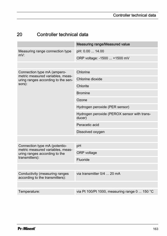
20 Controller technical data
Measuring range/Measured value
Measuring range connection typemV:
pH: 0.00 ... 14.00
ORP voltage: -1500 ... +1500 mV
Connection type mA (ampero‐metric measured variables, meas‐uring ranges according to the sen‐sors):
Chlorine
Chlorine dioxide
Chlorite
Bromine
Ozone
Hydrogen peroxide (PER sensor)
Hydrogen peroxide (PEROX sensor with trans‐ducer)
Peracetic acid
Dissolved oxygen
Connection type mA (potentio‐metric measured variables, meas‐uring ranges according to thetransmitters):
pH
ORP voltage
Fluoride
Conductivity (measuring rangesaccording to the transmitters):
via transmitter 0/4 ... 20 mA
Temperature: via Pt 100/Pt 1000, measuring range 0 ... 150 °C
Controller technical data
163
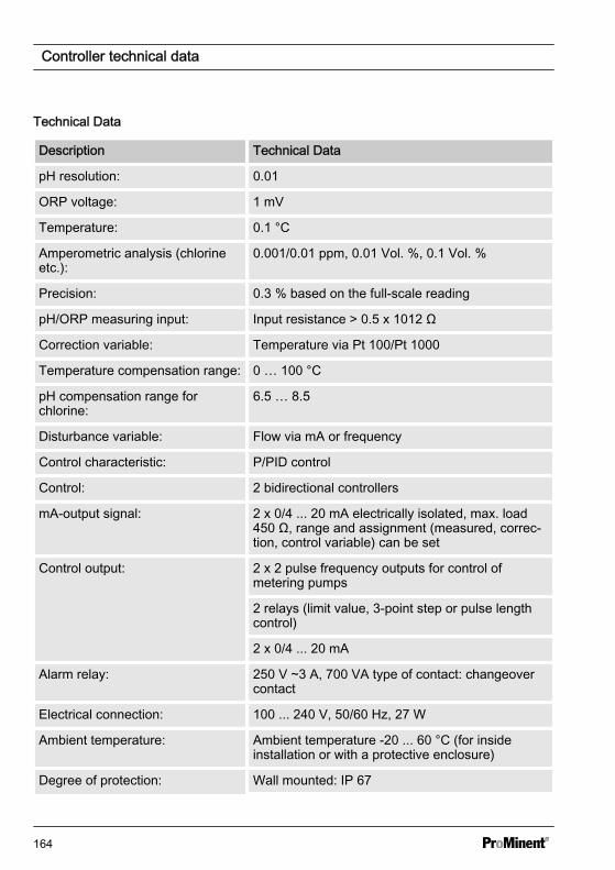
Technical Data
Description Technical Data
pH resolution: 0.01
ORP voltage: 1 mV
Temperature: 0.1 °C
Amperometric analysis (chlorineetc.):
0.001/0.01 ppm, 0.01 Vol. %, 0.1 Vol. %
Precision: 0.3 % based on the full-scale reading
pH/ORP measuring input: Input resistance > 0.5 x 10¹² Ω
Correction variable: Temperature via Pt 100/Pt 1000
Temperature compensation range: 0 … 100 °C
pH compensation range forchlorine:
6.5 … 8.5
Disturbance variable: Flow via mA or frequency
Control characteristic: P/PID control
Control: 2 bidirectional controllers
mA-output signal: 2 x 0/4 ... 20 mA electrically isolated, max. load450 Ω, range and assignment (measured, correc‐tion, control variable) can be set
Control output: 2 x 2 pulse frequency outputs for control ofmetering pumps
2 relays (limit value, 3-point step or pulse lengthcontrol)
2 x 0/4 ... 20 mA
Alarm relay: 250 V ~3 A, 700 VA type of contact: changeovercontact
Electrical connection: 100 ... 240 V, 50/60 Hz, 27 W
Ambient temperature: Ambient temperature -20 ... 60 °C (for insideinstallation or with a protective enclosure)
Degree of protection: Wall mounted: IP 67
Controller technical data
164

Description Technical Data
Control cabinet mounted: IP 54
In accordance with NEMA 4X (air-tightness)
Tests and certifications: CE, MET (corresponding to UL as per IEC 61010)
Material: Housing PC with flame-proofed configuration
Dimensions: 250 x 220 x 122 mm (WxHxD)
Weight: Net 2.1 kg
Controller technical data
165
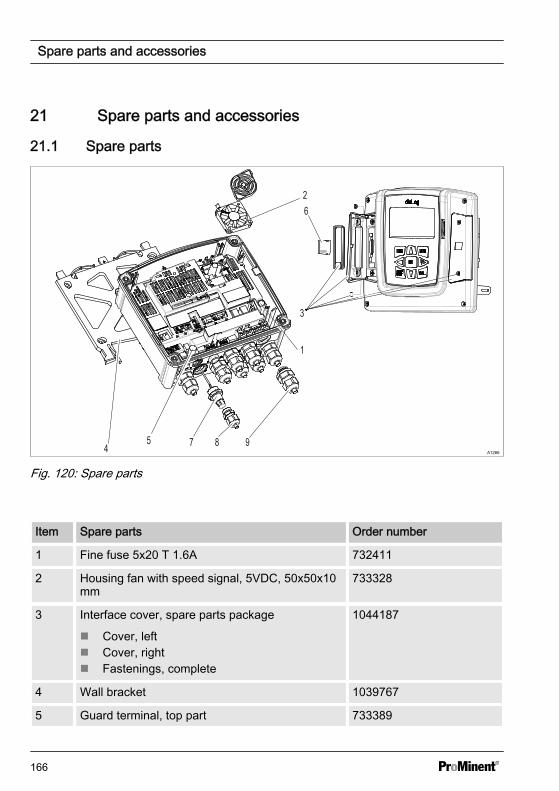
21 Spare parts and accessories
21.1 Spare parts
1
2
5 9874
3
6
A1266
Fig. 120: Spare parts
Item Spare parts Order number
1 Fine fuse 5x20 T 1.6A 732411
2 Housing fan with speed signal, 5VDC, 50x50x10mm
733328
3 Interface cover, spare parts package
n Cover, leftn Cover, rightn Fastenings, complete
1044187
4 Wall bracket 1039767
5 Guard terminal, top part 733389
Spare parts and accessories
166
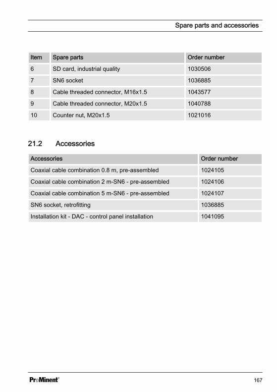
Item Spare parts Order number
6 SD card, industrial quality 1030506
7 SN6 socket 1036885
8 Cable threaded connector, M16x1.5 1043577
9 Cable threaded connector, M20x1.5 1040788
10 Counter nut, M20x1.5 1021016
21.2 Accessories
Accessories Order number
Coaxial cable combination 0.8 m, pre-assembled 1024105
Coaxial cable combination 2 m-SN6 - pre-assembled 1024106
Coaxial cable combination 5 m-SN6 - pre-assembled 1024107
SN6 socket, retrofitting 1036885
Installation kit - DAC - control panel installation 1041095
Spare parts and accessories
167
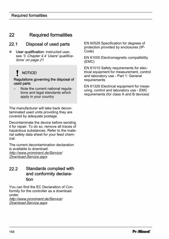
22 Required formalities
22.1 Disposal of used partsn User qualification: instructed user,
see Ä Chapter 4.4 ‘Users' qualifica‐tions’ on page 21
NOTICE!
Regulations governing the disposal ofused parts– Note the current national regula‐
tions and legal standards whichapply in your country
The manufacturer will take back decon‐taminated used units providing they arecovered by adequate postage.
Decontaminate the device before sendingit for repair. To do so, remove all traces ofhazardous substances. Refer to the mate‐rial safety data sheet for your feed chem‐ical.
The current decontamination declarationis available to download:http://www.prominent.de/Service/Download-Service.aspx
22.2 Standards complied withand conformity declara‐tion
You can find the EC Declaration of Con‐formity for the controller as a downloadunderhttp://www.prominent.de/Service/Download-Service.aspx
EN 60529 Specification for degrees ofprotection provided by enclosures (IP-Code)
EN 61000 Electromagnetic compatibility(EMC)
EN 61010 Safety requirements for elec‐trical equipment for measurement, controland laboratory use - Part 1: Generalrequirements
EN 61326 Electrical equipment for meas‐uring, control and laboratory use - EMCrequirements (for class A and B devices)
Required formalities
168

23 GlossarySlope of the pH sensor
The slope or sensitivity of a pH sensor isdefined as the quotient of the voltageemitted in mV per pH level. In theory, apH sensor should generate a voltage of+59.16 mV per pH level at 25 °C. In time,the slope flattens off, initially slowly butlater more quickly. That is why it is impor‐tant that this change is compensated forduring calibration. As with zero point com‐pensation, slope compensation has to berepeated at specific intervals dependingon the application.
Zero point of the pH sensor
The zero point of the pH sensor is the pH-value at which the sensor potential is0 mV.
Asymmetric potential of a pH sensor
The asymmetric potential of a pH sensoris the potential difference that occurswhen the pH sensor is immersed in a sol‐ution, which corresponds to the internalelectrolytes. Ideally the potential differ‐ence is 0 mV.
Glass break detection
[ON] / [OFF] : Switches the pH sensor'sglass break detection [ON] or [OFF]. Thefactory setting is [OFF]. The controllershows a fault message when a fault isdetected when the setting is [ON].The glass break detection monitors the pHsensor to detect whether the pH sensor'spH-sensitive glass membrane is broken.In the event of the glass membranebreaking, the pH sensor's resistancebecomes smaller, approx. 2 mega-Ω . Thecontroller can analyse this change inresistance. The controller emits a faultmessage and control is stopped. This faultcannot be acknowledged.
The pH sensor's glass membrane alsohas low resistance when the process tem‐perature increases. If the process tem‐perature is approximately > 60°C, thedetection threshold of 2 mega-Ω has beenreached. At process temperatures of> 60°C, glass breakage is detectedalthough no glass has broken. In order toavoid a false alarm, switch off glass breakdetection at process temperatures of> 60 °C .
Glossary
169

Cable break detection
[ON] / [OFF] : Switches cable break detec‐tion of the coaxial cable [ON] or [OFF].The factory setting is [OFF]. If the con‐troller has the setting [ON], it displays analarm message if an error is detected.
The cable break detection device monitorsa pH sensor with a coaxial connectioncable to determine whether a break existsin the coaxial connection cable. If a breakexists in the coaxial connection cable, theresistance increases enormously toapproximately 1 giga-Ω. The controllercan interpret this resistance change. Thecontroller generates an error messageand control is stopped. This error cannotbe acknowledged.
The glass membrane of the pH sensorbecomes highly resistant when theprocess temperature falls. Once theprocess temperature is approx. < 15 °Cthe detection threshold of 1 gig-Ω isreached. For process temperatures< 15 °C a cable break is detected eventhough no cable break exists. So that anerror alarm is avoided, cable break detec‐tion must be switched off at process tem‐peratures < 15 °C.
Measuring range of the measuring trans‐ducer
Select the measuring range. The meas‐uring range is printed on the nameplate ofthe measuring transducer. An incorrectmeasuring range will lead to an incorrectmeasurement.
Measuring range of the sensors
Select the measuring range. The meas‐uring range is given on the sensor name‐plate. An incorrect measuring range leadsto an incorrect measurement.
Measured variable chlorine, bromine,chlorine dioxide, chlorite, dissolvedoxygen and ozone:
The measured variables chlorine , bro‐mine, chlorine dioxide, chlorite, dissolvedoxygen and ozone are always measuredusing a mA signal because the measuringtransducer is located in the sensor.
The temperature compensation takesplace automatically inside the sensor(exception: CDP, chlorine dioxide sensor).For further information see the operatinginstructions of the sensor used.
Measured variable conductivity [mA]
When measuring conductivity [mA], use ofa measuring transducer is a prerequisite,e.g. a measuring transducer DMTa con‐ductivity. A conductivity sensor cannot bedirectly connected to the controller.
Measuring range:
n Select the measuring range corre‐sponding to the measuring range ofthe measuring transducer used. Anincorrect measuring range leads to anincorrect measurement.
Temperature:
n The temperature measurement isused only for information or recordingpurposes, but not however for tem‐perature compensation. Temperaturecompensation is carried out in themeasuring transducer.
Glossary
170
Measured variable pH [mA]:
If the measured variable ‘pH [mA]’ , i.e.pH measurement using a mA signal, isselected, then the possibility of sensormonitoring for cable or glass breaks is nolonger available.
For a pH measurement using a mA signal,either a DMTa or a pH-V1 measuringtransducer is connected to the pH sensor.A 2-conductor connection cable is usedbetween the DMTa-/pH-V1 measuringtransducer and the controller. The con‐nection cable supplies the DMTa-/pH-V1measuring transducer and routes themeasured value as a 4 ... 20 mA signal tothe controller.
When using the DMTa measuring trans‐ducer or the measuring transducer ofanother supplier, the measuring rangeallocation must be set to the followingvalues:
n 4 mA = 15.45 pHn 20 mA = -1.45 pH
With a pH-V1 measuring transducer, thesetting of the measuring range allocationis automatically specified.
Measured variables ORP [mV], ORP [mA]
If the measured variable ‘ ORP [mV]’ or‘ORP [mA]’ is selected, measurement ofthe process temperature is only possiblefor information or recording purposes.
For the measured variable ‘ORP [mV]’ ,the measuring range is fixed in the range-1500 mV ... + 1500 mV.
For the measured variable ‘ORP [mA]’ ,the measuring range is dependent on theRH-V1 measuring transducer and is 0 ...+1000 mV.
Measured variable temperature [mA], (asmain measured variable):
For the measured variable ‘Temperature[mA]’ use of a DMTa temperature meas‐uring transducer or a Pt100V1 measuringtransducer is prerequisite. The measuringrange is: 0 ... 100 °C. A temperaturesensor cannot be connected directly to thecontroller.
Measured variable temperature [Pt100X],(as main measured variable)
The temperature sensor Pt100 or Pt1000can be directly connected to the measure‐ment input of the controller. The meas‐uring range is: 0 ... 150 °C
Temperature measurement for the meas‐ured variable ORP
If the measured variable ORP [mV] orORP [mA] is selected, measurement ofthe process temperature is only possiblefor information or recording purposes. Forthe measured variable ORP [mV], themeasuring range is fixed in the range- 1500 mV ... + 1500 mV. For the meas‐ured variable ORP [mA], the measuringrange is dependent on theRH-V1 measuring transducer and is0 ...+ 1000 mV.
The measured variable pH [mV]
The pH sensor of the measured variablepH [mV] is connected using a coaxialcable via which the mV signal is trans‐mitted to the controller. This measurementcan be used if the cable is less than 10metres in length.
Glossary
171
Sensor type:
First select the sensor type. The sensortype is given on the sensor nameplate.This sensor selection is necessary andactivates the sensor-specific data in thecontroller.
Temperature compensation
This function is used to compensate forthe temperature influence on the meas‐urement. The process temperature is setin the DMTa measuring transducer whenusing a DMTa measuring transducer
Temperature: [Off] / [Manual] / [Automatic]
n [Off] switches the process tempera‐ture setting off
n [Manual] permits manual processtemperature setting
n [Automatic] uses a measured processtemperature
Temperature compensation
This function is used for compensation ofthe temperature influence of the processon measurement.
Temperature: [Off] / [Manual] / [Automatic]
n [Off] switches the process tempera‐ture setting off
n [Manual] makes possible a manualspecification of the process tempera‐ture
n [Automatic] uses a measured processtemperature. Automatic measurementof the temperature using the tempera‐ture sensor, e.g. Pt1000. For pH,CDP and fluoride, temperature com‐pensation can be switched [ON] or[OFF] in the menu.
Temperature: Off / Manual / Automatic
For the ‘Off’ setting, the temperatureinfluence of the process water on the pHmeasurement is calculated at the fixedtemperature value of 25 °C. A tempera‐ture measurement does not take place.
For the ‘Manual’ setting, the previouslydetermined process temperature must bemanually entered in the controller. The‘Manual’ function only makes sense if theprocess temperature is stable (± 2 °C). Ifthe process temperature changes quickly> ± 5 °C, then the ‘Automatic’ setting isrequired.
For the ‘automatic’ setting, a type [Pt100]or [Pt1000] temperature sensor must beconnected. The controller automaticallydetects which type of temperature sensoris connected. To achieve accurate tem‐perature compensation, the temperaturesensor must be in the same process wateras the sensor used for the measured vari‐able.
Further input options are shown under the‘Automatic’ setting:
Temperature
The temperature measurement is usedonly for information and recording pur‐poses, but not for temperature compensa‐tion. Temperature compensation is per‐formed in the sensor. If the measuredvariable [Chlorine dioxide] and the [CDP]type of sensor have been selected, then aseparate temperature measurement isneeded for temperature compensation.
Glossary
172

The temperature offset
The setting ‘Temperature offset’ makes itpossible to match the measured tempera‐ture to a reference value. An offset of-10.0 ... +10.0 °C is possible.
Additive basic load
The additive basic load should balanceout a continuous requirement for a chem‐ical in order to maintain the setpoint. Theadditive basic load can be set in the range-100 % … +100 %. The additive basicload is added to the control variable deter‐mined by the controller and is effective inboth control directions. E.g., if the controlvariable calculated by the controller
n y= -10 % and the additive basic loadequals +3 %, then the resulting con‐trol variable = Y= -10 % + (+3 %)= -7%
n y= 10% and the additive basic loadequals +3 %, the resulting control var‐iable = Y= 10 % + (+3 %)= 13 %
n y= 0 % and the additive basic loadequals +3 %, the resulting control var‐iable = Y= 0 % + (+3 %)= 3 %
Control time control
The checkout time should prevent over‐dosing as a result of a malfunction. Duringthe checkout time the control variable iscompared with an adjustable [threshold](= control variable threshold). Dependingon the control direction, you can set dif‐ferent values for the checkout times[Checkout time up] to increase and[Checkout time down] to decrease thevalue. The checkout times depend on theconcentration of the metered chemicals. If
the [threshold] is exceeded, timerecording starts (checkout time). If duringthe checkout time the variable again fallsbelow the threshold, then the time is againreset to [0] s.
However if the disturbance variableremains above the threshold for longerthan the checkout time, then the reactionof the controller can be selected[Checkout time reset] = [Normal] thisselection stops the control immediately.To enable restarting, an operator mustacknowledge the fault once the cause ofthe fault has been cleared.[Checkout time reset] = [Auto] this selec‐tion automatically resets the function, ifthe threshold is again undershot and thecontrol restarts automatically.
Dead zone
The dead zone is defined by an upper andlower setpoint. The dead zone only func‐tions with a 2-way control and only if anactuator is available for each direction.The dead zone should have the effect ofpreventing the control path from starting tooscillate. If the measured value lies withinboth the setpoints, then no control of theactuators takes place even with a PI / PIDcontroller. Application 2-way neutralisa‐tion.
Controller type
n P mono-directionaln P bidirectionaln PID mono-directionaln PID bidirectionaln Manualn Off
Glossary
173
P controller: This is used with integratingcontrol paths (for example batch neutrali‐sation). If control deviation becomes less,then the control of the actuator becomesless (proportional relationship). Once thesetpoint is reached, then the controloutput is 0 %. However, the setpoint isnever exactly reached, thereby creating aconstant control deviation. Oscillationscan occur when stabilising large changes.
PI controller: This is used with non-inte‐grating control paths (for example in-lineneutralisation), where oscillation has to beavoided and where no remaining controldeviation may occur, i.e. the setpointalways has to be maintained. A constantaddition of metering chemicals is required.It is not a malfunction if the controller doesnot stop when the setpoint is reached.
PID controller: This controller type has theproperties of a PI controller. Due to thedifferentiating control part, it also offers acertain level of foresight and can react toforthcoming changes. It is used whenmeasurement spikes occur in the meas‐urement curve and these have to bequickly regulated out.
P, PI and PID controllers are continuouscontrollers. The control variable can haveany value within the control range from-100 % … +100 %.
Manual: If [Manual] controller type isselected, then a control variable within arange of -100 % … 100 % can be entered.This function is used to test the cablingand the actuator.
Off: The control function is deactivated.The device works only as a measuringtransducer.
Setpoint
The setpoint specifies the target value forcontrol. The controller attempts to keepthe deviation between the setpoint andmeasured value as small as possible.
Ctrl output limitation (control variable limi‐tation)
Ctrl output limitation specifies the max‐imum control variable to be output. Thismakes sense if an actuator is over-dimen‐sioned and must not be opened to 100%.
[Ti]The time [Ti] is the integral action time ofthe I-controller (integral controller) in sec‐onds. The time [Ti] defines the time inte‐gration of the control deviation from thecontrol variable. The smaller the time [Ti],the greater the effect on the control vari‐able. An infinitely long time [Ti] results in apure proportional control.
The time [Ti] is the time that an I-controlneeds to reach the equal size of controlvariable change that a P controller,although a P controller achieves thischange immediately.
Td
The time Td is the differentiation time ofthe D-controller (differential controller) inseconds. The D-controller reacts to therate of change of the measured value.
Glossary
174
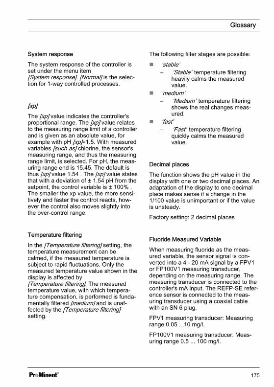
System response
The system response of the controller isset under the menu item[System response]. [Normal] is the selec‐tion for 1-way controlled processes.
[xp]The [xp] value indicates the controller'sproportional range. The [xp] value relatesto the measuring range limit of a controllerand is given as an absolute value, forexample with pH [xp]=1.5. With measuredvariables [such as] chlorine, the sensor'smeasuring range, and thus the measuringrange limit, is selected. For pH, the meas‐uring range end is 15.45. The default isthus [xp] value 1.54 . The [xp] value statesthat with a deviation of ± 1.54 pH from thesetpoint, the control variable is ± 100% .The smaller the xp value, the more sensi‐tively and faster the control reacts, how‐ever the control also moves slightly intothe over-control range.
Temperature filtering
In the [Temperature filtering] setting, thetemperature measurement can becalmed, if the measured temperature issubject to rapid fluctuations. Only themeasured temperature value shown in thedisplay is affected by[Temperature filtering]. The measuredtemperature value, with which tempera‐ture compensation, is performed is funda‐mentally filtered [medium] and is unaf‐fected by the [Temperature filtering]setting.
The following filter stages are possible:
n ‘stable’– ‘Stable’ temperature filtering
heavily calms the measuredvalue.
n ‘medium’– ‘Medium’ temperature filtering
shows the real changes meas‐ured.
n ‘fast’– ‘Fast’ temperature filtering
quickly calms the measuredvalue.
Decimal places
The function shows the pH value in thedisplay with one or two decimal places. Anadaptation of the display to one decimalplace makes sense if a change in the1/100 value is unimportant or if the valueis unsteady.
Factory setting: 2 decimal places
Fluoride Measured Variable
When measuring fluoride as the meas‐ured variable, the sensor signal is con‐verted into a 4 - 20 mA signal by a FPV1or FP100V1 measuring transducer,depending on the measuring range. Themeasuring transducer is connected to thecontroller's mA input. The REFP-SE refer‐ence sensor is connected to the meas‐uring transducer using a coaxial cablewith an SN 6 plug.
FPV1 measuring transducer: Measuringrange 0.05 ...10 mg/l.
FP100V1 measuring transducer: Meas‐uring range 0.5 ... 100 mg/l.
Glossary
175
Peracetic acid measured variable
Peracetic acid as a measured variable ismeasured via one of the two mA sensorinputs. Temperature compensation is per‐formed in the sensor. An additionally con‐nected temperature sensor is only usedfor display and data recording with a datalogger and can be issued on a mA-outputvia field bus or web server.
Hydrogen peroxide as a measured vari‐able [mA]
Hydrogen peroxide as a measured vari‐able is measured via one of the two mAsensor inputs. Temperature compensationis performed in the sensor. An additionallyconnected temperature sensor is onlyused for display and data recording with adata logger and can be issued on a mA-output via field bus or web server.
Measured variable [mA general]
With the [mA general] measured variable,various preselected measured variablecan be selected and/or one measured var‐iable can also be freely edited with its unitof measure. The temperature measure‐ment cannot be used for compensationpurposes, because the influence of thetemperature measurement on the meas‐ured value is not known. In principle, thesettings are performed in the same wayas with the other measured variable. Astandardised calibrated signal is expectedby the controller from each connecteddevice
Two channel version
If a second measuring channel is avail‐able (dependent on the identity code,channel 2), then this second measuringchannel can be configured according tothe descriptions of the first measuringchannel.
Two channel version with two identicalmeasured variables
If the measured variables of measuringchannel 1 and measuring channel 2 arechosen identically, then the menu item[Differential meas]appears in the[Measurement] menu. The[Differential meas] function is switched off"ex works". The function[Differential meas] can be activated andthe calculation [K1-K2] executed. Theresult of the calculation is displayed in themain display 2 by pressing the key or
key. By pressing the or key againyou jump back to the main display 1. Thelimit value criteria for the[Differential meas] can be set in the menu[Limit values].
Glossary
176
24 Index1, 2, 3 ...[Relay timer]....................................... 131AAccessibility......................................... 25Accessories........................................ 167Actuating outputs............... 89, 92, 95, 97Actuator.............................................. 122Additive and multiplicative feedfor‐ward control....................................... 112An external manufacturer's transmitter 34Applicational example of additiveinterference variable.......................... 112BBacklight.............................................. 51Bleeding............................................... 49Brightness............................................ 51CCalibrating Amperometric meas‐ured Variables...................................... 84Calibrating Chlorine............................. 84Calibrating the "Conductivity"measured variable............................... 98Calibrating the "Temperature"measured variable............................... 99Calibrating the zero point..................... 86Calibration............................................ 61Calibration log book........................... 140Caulking strip....................................... 30Configuration of the data log book..... 144Configuring the log books.................. 141Connecting the chlorine sensorwith controllers with two channels........ 33Connection of the transmitter DTMa.... 34Contrast............................................... 51
Control outputs..................................... 86Control panel installation...................... 28CSV format........................................ 143Cycle.................................................. 131DData backup....................................... 140Data input............................................. 73Data log book..................................... 140Data logger........................................ 140Declaration of Conformity.................. 168Degree of protection IP 54 .................. 43Degree of protection IP 67 .................. 43Delay period of the limit values.......... 121Destruction of the monitors................ 136EError log book.................................... 140FFoam rubber........................................ 30Function of the keys............................... 8GGeneral non-discriminatory approach.... 2IIndustrial and process water treatment 23KKey Lock.............................................. 13LLanguage settings................................ 12Large threaded connection (M 20 x1.5)....................................................... 43Limit exceeded................................... 121Limit value 1/2 (control variable)........ 131Limit value relay................................. 122
Index
177

Limit values........................................ 120MMaterial thickness ............................... 28Multiplicative interference variable..... 114Nnon-discriminatory approach.................. 2OOnly one sensor per unit...................... 33Operating Concept................................. 8Operating language....................... 12, 51PpH calibration....................................... 62pH measurement using a transmitter... 33Poor sensor operation and fluctu‐ating pH values during the process...... 71Potable water treatment....................... 23Projection of device.............................. 31Punched template................................ 28QQuestion: Are there disadvantageswith pH calibration with an externalsample?............................................... 71Question: How can I bleed thehydraulic installation?........................... 49Question: How can I carry out asoftware update?............................... 161Question: How can I import newlanguage versions?............................ 161Question: How can I reset theoperating language?............................ 51Question: How can I set or changethe operating language?...................... 12Question: How does the controlleroperate?................................................. 8Question: How does the key lockwork?................................................... 13
Question: How do I adjust the dis‐play brightness?................................... 51Question: How do I adjust the dis‐play contrast?....................................... 51Question: How do I connect atransmitter?.......................................... 34Question: How thick should thecontrol panel be to accommodatethe controller?...................................... 28Question: In which file format is thedata log book data?........................... 143Question: What accessories areavailable for the controller?................ 167Question: What are the effects of amultiplicative interference variable?... 114Question: What causes an additiveand multiplicative feedforward con‐trol?.................................................... 112Question: What does the relayfunction [Cycle] do?........................... 132Question: What does the relayfunction [Limit 1] or [Limit 2] bringabout?................................................ 131Question: What does the relayfunction [Limit value 1/2 (controlvariable)] do?..................................... 131Question: What does the relayfunction [Off] do?................................ 131Question: What does the relayfunction [Pulse length (PWM)] do?.... 132Question: What does the relayfunction [Relay timer] do?.................. 131Question: What optional accesso‐ries are available for the controller?..... 23Question: What should I considerwhen connecting passive monitors? . 136Question: What sort of applicationsare there?............................................. 23Question: What spare parts arethere?................................................. 166
Index
178
Question: What type of buffer solu‐tions do I need for a fluoride cali‐bration?.......................................... 81, 83Question: What type of buffer solu‐tions do I need for pH calibration?....... 66Question: What type of equipmentdoes the controller have as standard?. 23Question: Where do I find the [Sim‐ulation] function?................................ 147Question: Where do I find the Dec‐laration of Conformity?....................... 168Question: Which calibrationprocess can you use to calibrateamperometric measured variables?..... 85Question: Which calibrationprocess can you use to calibratethe DO measured variable?................. 91Question: Which calibrationprocess can you use to calibratethe fluoride value?................................ 80Question: Which calibrationprocess can you use to calibratethe ORP value?.................................... 76Question: Which calibrationprocess can you use to calibratethe pH value?....................................... 65Question: Which components areincluded as standard?.......................... 26Question: Which standards arecomplied with?................................... 168Question: Which values render pHcalibration valid?.................................. 67RReducing inserts.................................. 43Remove and refit the fluoridesensor in the in-line probe housing 80, 82Remove and refit the pH sensor inthe in-line probe housing...................... 66
Run in periods.............. 86, 89, 92, 94, 96SSafety information................................ 18SD cards............................................ 140Sensor function............ 86, 89, 92, 94, 96Service life of the SD card................. 140Setting the mA outputs....................... 136Simulation.......................................... 147Small threaded connection (M 12 x1.5)....................................................... 43Standards complied with.................... 168Standard signal outputs..................................... 86, 89, 93, 95, 97Strain relief........................................... 43Swimming pool water treatment........... 23TTerminal diagrams showing 1:1assignment........................................... 33Test container 1 with buffer solution.... 67Test container 1 with fluoride cali‐bration solution............................... 80, 82Test container 2 with buffer solution.... 67Test container 2 with fluoride cali‐bration solution..................................... 80The maximum file size is 2 GB.......... 145Timer relay......................................... 132UUpdate............................................... 161Users' qualifications............................. 21WWaste water treatment......................... 23ZZero point calibration......... 89, 92, 94, 96
Index
179
985250, 4, en_GB
© 2014
ProMinent GmbHIm Schuhmachergewann 5 - 1169123 HeidelbergTelephone: +49 6221 842-0Fax: +49 6221 842-419email: [email protected]: www.prominent.comThe latest version of the operating instructions are available on our homepage.