duh-211/211s · indentation the duh-211/211s measures dynamic hardness and evaluates the hardness...
TRANSCRIPT

C227-E024B
Dynamic Ultra Micro Hardness Testers
DUH-211/211S

System for Evaluating Thin Films, Surface-Treated Layers,and Microelectronic PartsDynamic Ultra Micro Hardness Testers
DUH-211/211S

B u i l d i n g o n o u r e x p e r i e n c e w i t h h a r d n e s s e v a l u a t i o n
t e c h n o l o g y f o r t h e m i c r o r a n g e , w e h a v e t a k e n o u r q u e s t
f o r g r e a t e r p r e c i s i o n a n d e a s e o f u s e t o t h e n e x t l e v e l .
O u r h a r d n e s s t e s t e r c a n m e a s u r e t h e s t r e n g t h
p r o p e r t i e s o f m a t e r i a l s u r f a c e s a n d m i c r o s c o p i c m a t e r i a l s
u s i n g n e w e v a l u a t i o n m e t h o d s s p e c i � e d i n I S O s t a n d a r d s .
Perform evaluation using the hardness and materials
parameters speci�ed in ISO 14577-1 (Annex A) *1) .
Evaluates hardness of a wide range of materials
T h i n � l m s
P l a s t i c s
R u b b e r s a n d e l a s t o m e r s
M e t a l l i c m a t e r i a l s
F i b e r s
B r i t t l e m a t e r i a l s
M i c r o s c o p i c e l e c t r o n i c c o m p o n e n t s
Test the surface strength of thin �lms, surface-treated layers such as ion-implanted layers
and nitride layers, as well as nonmetallic materials such as plastics, rubbers, and ceramics.
*1 ISO 14577-1 Metallic materials - Instrumented indentation test for hardness and materials parameters Part1: Test method
Annex A Materials parameters determined from the force/indentation depth date set
Standard used for new evaluation methods that continuously measure changes in test force and indentation depth which occur when an indenter is pressed into a
material, and for the evaluation of material hardness and strength properties such as Young's modulus and creep deformation
Contents
Materials and Applications
Features · Measurement Principle
Functions
Data Processing
P. 4 · 5
P. 6
P. 7
P. 8
ISO 14577-1 (Annex A)
Speci�cations
Optional Accessories
Related Product
P. 9
P. 10
P. 11
P. 12
M a t e r i a l s a n d A p p l i c a t i o n s
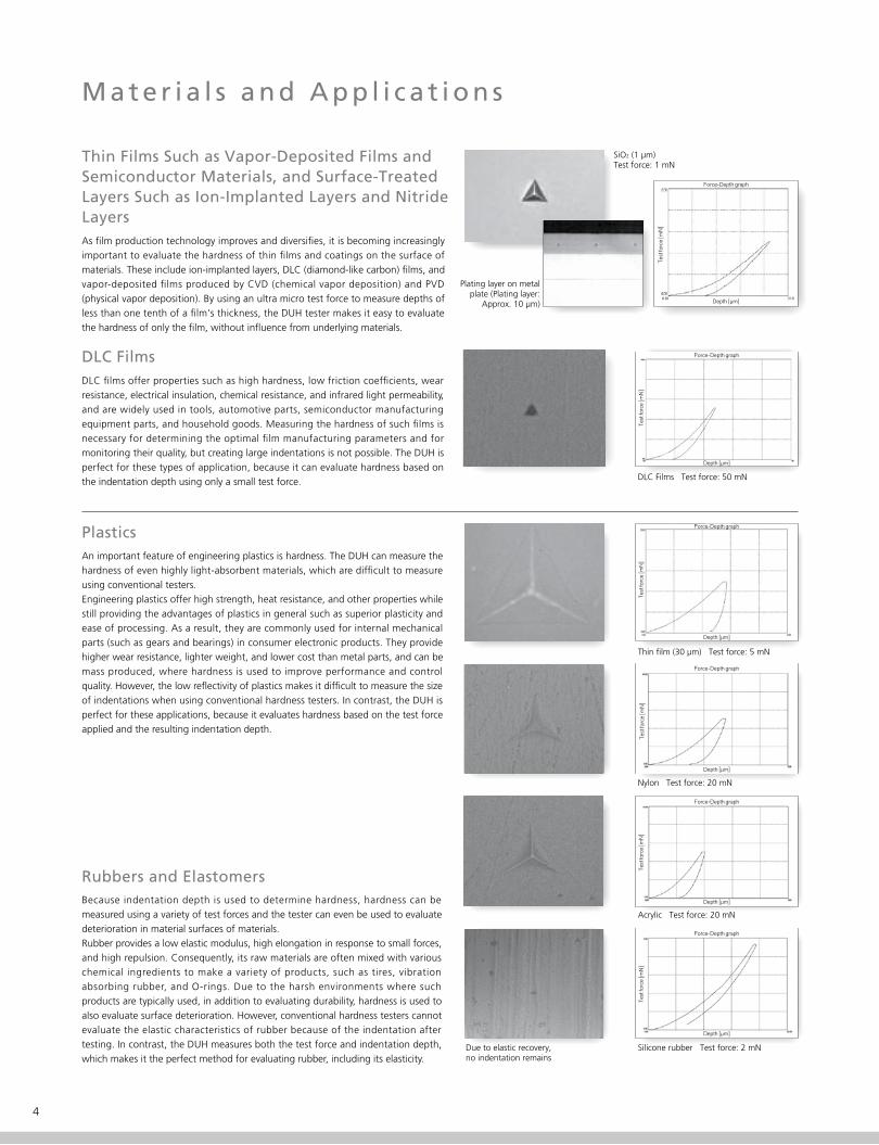
Thin Films Such as Vapor-Deposited Films and Semiconductor Materials, and Surface-Treated Layers Such as Ion-Implanted Layers and Nitride LayersAs �lm production technology improves and diversi�es, it is becoming increasingly important to evaluate the hardness of thin �lms and coatings on the surface of materials. These include ion-implanted layers, DLC (diamond-like carbon) �lms, and vapor-deposited �lms produced by CVD (chemical vapor deposition) and PVD (physical vapor deposition). By using an ultra micro test force to measure depths of less than one tenth of a �lm's thickness, the DUH tester makes it easy to evaluate the hardness of only the �lm, without in�uence from underlying materials.
DLC FilmsDLC �lms offer properties such as high hardness, low friction coef�cients, wear resistance, electrical insulation, chemical resistance, and infrared light permeability, and are widely used in tools, automotive parts, semiconductor manufacturing equipment parts, and household goods. Measuring the hardness of such �lms is necessary for determining the optimal �lm manufacturing parameters and for monitoring their quality, but creating large indentations is not possible. The DUH is perfect for these types of application, because it can evaluate hardness based on the indentation depth using only a small test force.
PlasticsAn important feature of engineering plastics is hardness. The DUH can measure the hardness of even highly light-absorbent materials, which are dif�cult to measure using conventional testers.Engineering plastics offer high strength, heat resistance, and other properties while still providing the advantages of plastics in general such as superior plasticity and ease of processing. As a result, they are commonly used for internal mechanical parts (such as gears and bearings) in consumer electronic products. They provide higher wear resistance, lighter weight, and lower cost than metal parts, and can be mass produced, where hardness is used to improve performance and control quality. However, the low re�ectivity of plastics makes it dif�cult to measure the size of indentations when using conventional hardness testers. In contrast, the DUH is perfect for these applications, because it evaluates hardness based on the test force applied and the resulting indentation depth.
Rubbers and ElastomersBecause indentation depth is used to determine hardness, hardness can be measured using a variety of test forces and the tester can even be used to evaluate deterioration in material surfaces of materials.Rubber provides a low elastic modulus, high elongation in response to small forces, and high repulsion. Consequently, its raw materials are often mixed with various chemical ingredients to make a variety of products, such as tires, vibration absorbing rubber, and O-rings. Due to the harsh environments where such products are typically used, in addition to evaluating durability, hardness is used to also evaluate surface deterioration. However, conventional hardness testers cannot evaluate the elastic characteristics of rubber because of the indentation after testing. In contrast, the DUH measures both the test force and indentation depth, which makes it the perfect method for evaluating rubber, including its elasticity.
SiO2 (1 µm)Test force: 1 mN
Thin �lm (30 µm) Test force: 5 mN
Nylon Test force: 20 mN
Acrylic Test force: 20 mN
Silicone rubber Test force: 2 mNDue to elastic recovery,no indentation remains
DLC Films Test force: 50 mN
Plating layer on metal plate (Plating layer:
Approx. 10 µm)
4
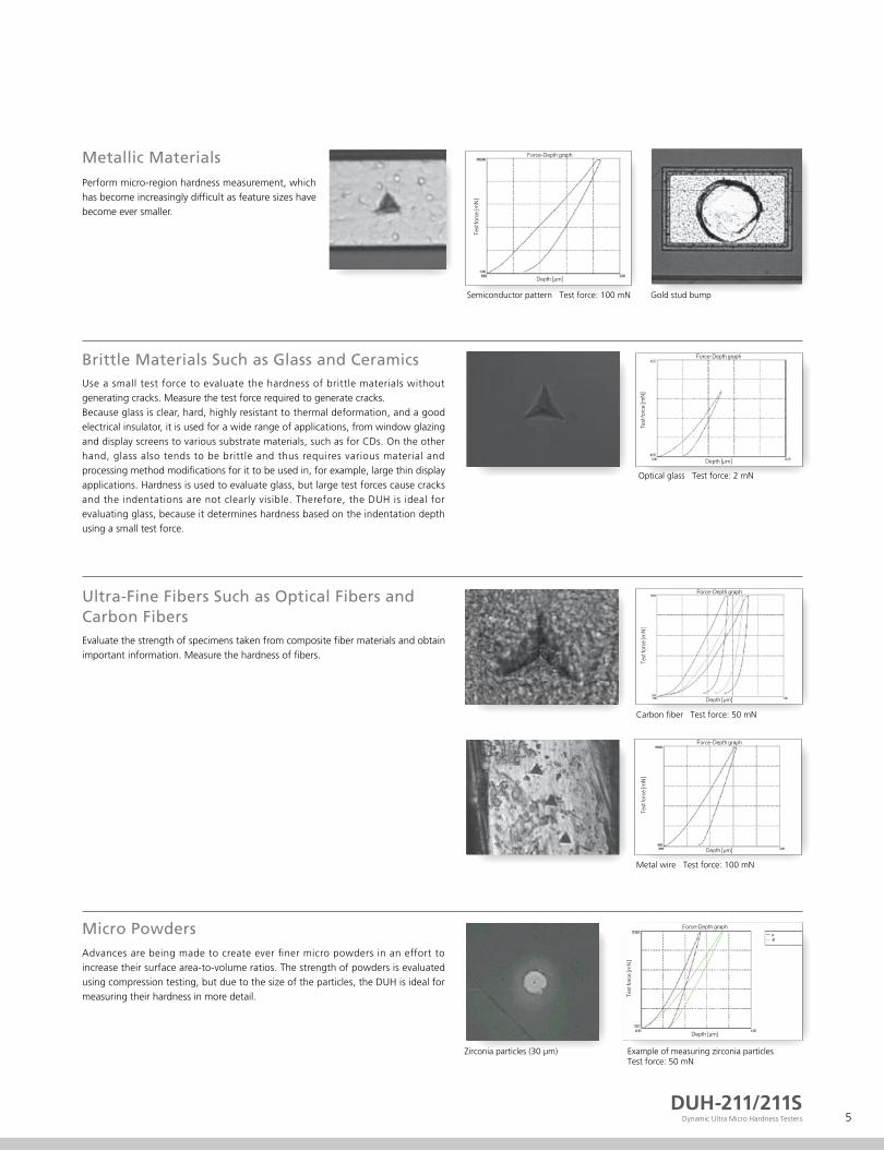
Perform micro-region hardness measurement, which has become increasingly dif�cult as feature sizes have become ever smaller.
Metallic Materials
Evaluate the strength of specimens taken from composite �ber materials and obtain important information. Measure the hardness of �bers.
Ultra-Fine Fibers Such as Optical Fibers andCarbon Fibers
Use a small test force to evaluate the hardness of brittle materials without generating cracks. Measure the test force required to generate cracks.Because glass is clear, hard, highly resistant to thermal deformation, and a good electrical insulator, it is used for a wide range of applications, from window glazing and display screens to various substrate materials, such as for CDs. On the other hand, glass also tends to be brittle and thus requires various material and processing method modi�cations for it to be used in, for example, large thin display applications. Hardness is used to evaluate glass, but large test forces cause cracks and the indentations are not clearly visible. Therefore, the DUH is ideal for evaluating glass, because it determines hardness based on the indentation depth using a small test force.
Advances are being made to create ever �ner micro powders in an effort to increase their surface area-to-volume ratios. The strength of powders is evaluated using compression testing, but due to the size of the particles, the DUH is ideal for measuring their hardness in more detail.
Brittle Materials Such as Glass and Ceramics
Micro Powders
Semiconductor pattern Test force: 100 mN
Metal wire Test force: 100 mN
Optical glass Test force: 2 mN
Example of measuring zirconia particlesTest force: 50 mN
Zirconia particles (30 µm)
Carbon �ber Test force: 50 mN
Gold stud bump
DUH-211/211SDynamic Ultra Micro Hardness Testers 5

F e a t u r e s
1. Evaluation of Hardness and Material Parameters in Accordance with Standards (ISO 14577-1 Annex A)Measure the behavior of a specimen as an indenter is pressed into it and evaluate the
hardness, elastic modulus, and amount of work done during indentation, in compliance
with and ISO 14577-1 (instrumented indentation test for hardness) Annex A.
2. Highly Precise Evaluation of Elastic ModulusPerform highly precise evaluation of the elastic modulus, using correction based on
instrument rigidity and the shape of the intender tip*1.
3. Low Test Force with Measurement Resolution of 0.196 µNControl the test force using a high resolution of 0.196 µN. This allows measurement
of material strength properties in micro regions and in the outermost surfaces of
specimens.
4. Ultra-Wide Test Force Range of 0.1 to 1,961 mNUse a wide test range of 0.1 to 1,961 mN for measurement, and test a variety of
industrial materials, including rubber, plastics, and ceramics.
5. High-Precision Measurement of Indentation Depth
No need to measure the actual indentation.
Specimen indentation depth can be measured in units of 0.0001 µm for depths up
to 10 µm.
6. Supports a Wide Range of Testing Methods
Record the relationship between the test force and the indentation depth. Test both
the unload and load processes. Use the DUH-211S to perform cyclic load-unload
tests and step load-unload tests.
7. Supports Vickers Hardness TestA function to measure the length of diagonals is provided as a standard feature. This
function allows you to measure the hardness that corresponds only to plastic
deformation, Vickers hardness, and Knoop hardness. (A Vickers indenter and Knoop
indenter are available as options.) Maximum microscope magni�cation is 500×
(1000× is available as an option).
*1 Indenter tip shape correction is only available for the 115-degree triangular pyramid indenter.
Shape correction is not available for other indenters.
M e a s u r e m e n t P r i n c i p l e
Electromagnetic force is used to press an indenter (standard type: 115° triangular pyramid) against a specimen. Pressing force is increased at a constant
rate, from 0 to the preset test force. Indentation depth is automatically measured as the indenter is pressed against the specimen. This allows dynamic
measurement of changes that occur in the specimen's resistance to deformation during the indentation process, and obtains a wide variety of data. During
indentation the DUH-211/211S measures dynamic hardness and evaluates the hardness that corresponds to both plastic and elastic deformation. Also, if
the indentation size is large enough to be observed with a microscope, hardness can be calculated using just the plastic deformation, by measuring the
diagonal length of the indentation.
Expressions for Dynamic Hardness
d
d2
d1
d: average
d2
d1
Load F (mN)
h
Indentation depth h (µm)Specimen
Diagonal lengths d1 and d2 (µm)(Used with Vickers indenter)
Even though the theoretical unit for these hardness expressions is kgf/mm2, it is normally not used.
①
① ② ④③
d
Expressions for Martens Hardness (ISO 14577-1 Annex A)
Hardness Expressions Based on Diagonal Length
① ③
②115° triangular pyramid indenter (standard)HM115 = 1000 F / 26.43 × h2 [N/mm2]
115° triangular pyramid indenter (standard)HT115 = 160.07 × F / d2
100° triangular pyramid indenter (option)HT100 = 121.53 × F / d2
Knoop indenter (option)HK = 1451.1 × F / d2
Vickers indenter (option)HV = 189.10 × F / d2
115° triangular pyramid indenter (standard)DHT115 = 3.8584 × F / h2
100° triangular pyramid indenter (option)DHT100 = 15.018 × F / h2
Vickers indenter (option)DHV = 3.8584 × F / h2
Knoop indenter (option)DHK = 1.5583 × F / h2
Vickers indenter (option)HMV = 1000 F / 26.43 × h2 [N/mm2]
② ④
6
F u n c t i o n s
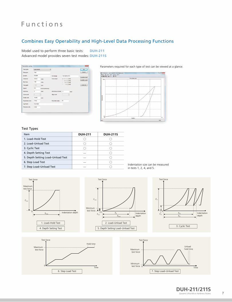
Combines Easy Operability and High-Level Data Processing Functions
Model used to perform three basic tests:Advanced model provides seven test modes:
DUH-211DUH-211S
Parameters required for each type of test can be viewed at a glance.
Test Types
Item
1. Load–Hold Test
2. Load–Unload Test
3. Cyclic Test
4. Depth Setting Test
5. Depth Setting Load–Unload Test
6. Step Load Test
7. Step Load–Unload Test
DUH-211
○
○
○
—
—
—
—
DUH-211S
○
○
○
○
○
○
○Indentation size can be measuredin tests 1, 2, 4, and 5.
Indentation depth
Maximum test force
Fmax
hmax
Test force
0
4. Depth Setting Test
1. Load–Hold Test
Fmax
Fminhp
hmax
Indentationdepth
Test force
Minimum test force
0
5. Depth Setting Load–Unload Test
2. Load–Unload Test
Indentationdepth
Test force
Fn2
Fn1
hn2
hn1
0
3. Cyclic Test
Time
Hold time
0
Test force
Maximum test force
6. Step Load Test
Time
Unload hold time
0
Test force
Maximum test force
Minimum test force
7. Step Load–Unload Test
DUH-211/211SDynamic Ultra Micro Hardness Testers 7

D a t a P r o c e s s i n g
Simply set the required items to obtain the desired information.
Data Processing Items · Results display · Data output for test force and depth · Graph output for test force and depth · Graph output for hardness and depth · Graph output for hardness between 2 points and depth · Graph output for depth and time · Graph output for hardness and test force · Graph output for depth squared and test force · Hardness calculation based on preliminary test force · Graph output for hardness and parameters · Calculation of converted hardness values · Repeated changes of surface detection points · Calculation of elastic modulus · ASCII �le output
Example of test results display (load–unload test)
Graph of depth squared against test force
Calculation of elastic modulus
8
I S O 1 4 5 7 7 - 1 ( A n n e x A ) C o m p l i a n t E v a l u a t i o n(Instrumented Indentation Test for Hardness)
Relationship between test force and indentation depth during indentation process can,in accordance with ISO 14577-1 (Annex A), be used to evaluate hardness, elastic modulus,and amount of work done.
HM
HMs
Hit
Eit
: Martens hardness
: Martens hardness obtained from gradient of graph of test force
versus depth
: Indentation hardness
: Indentation elastic modulus
Cit
ηit
HV*
: Indentation creep
: Indentation work rate
: Vickers hardness obtained by converting Hit
1. Indentation Elastic Modulus (Eit)De�nition of indentation elastic modulus (Eit) states
that Eit is obtained from the inclination of the tangent
used to calculate the indentation hardness (Hit), and is
equivalent to Young's modulus.
S = dP/dh = 2 · Er · Ap0.5/π0.5
Ap = 23.96 · hc2
hc = hmax − 0.75(hmax − hr)
Er
1-Eit
1−νs2-
Ei
1−νi2
-= +
If Poisson's ratio for the specimen is set in the test parameters, the DUH-211/211S calculates Eit.
Otherwise, the DUH-211/211S calculates (1− νS2)/Eit.
Here,
Er
Ei
νi
Eit
νs
S
Ap
hc
hr
: Converted elastic modulus based on indentation contact
: Young's modulus for indenter (1.14 × 10¹² N/m2)
: Poisson's ratio for indenter (0.07)
: Indentation elastic modulus
: Poisson's ratio for specimen
: Inclination at start of unloading (inclination of straight-line approximation)
: Projected contact area (23.96 is a constant that applies when using a 115° triangular pyramid indenter.)
: Depth of the contact of the indenter with the test piece at Fmax
: Point of intersection of the tangent to curve b at Fmax with the indentation depth-axis
Force
FmaxLoad–unload curve
hr hmax
Depth
2. Plastic and Elastic Portions of Indentation Work (ηit)A portion of the total mechanical work performed by indentation, Wtotal, is
consumed due to plastic deformation, Wplast. The remaining portion of the
total mechanical work corresponds to elastic deformation, Welast, which is
released when the test force is unloaded. This work is de�ned by W = ∫ Fdh. Wtotal = Welast + Wplast
Wtotal
Welast-=ηit (%)
Testforce
Depth0
Wplast
Welast
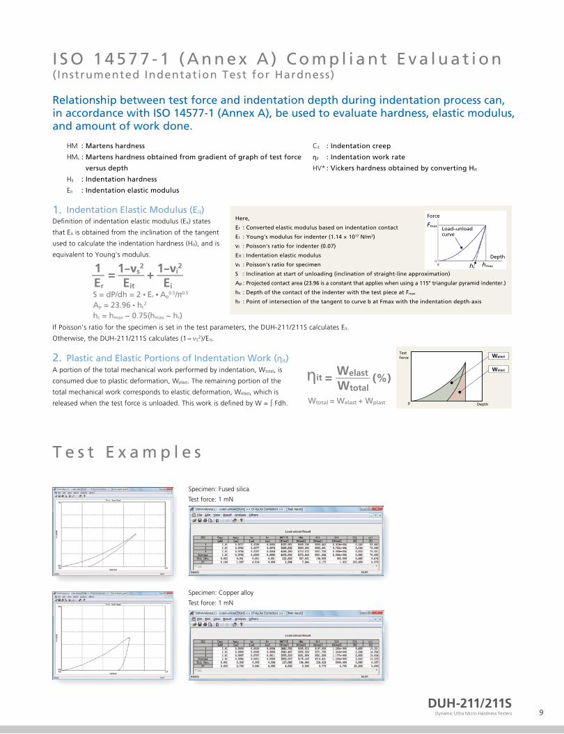
T e s t E x a m p l e s
Specimen: Fused silica
Test force: 1 mN
Specimen: Copper alloy
Test force: 1 mN
DUH-211/211SDynamic Ultra Micro Hardness Testers 9
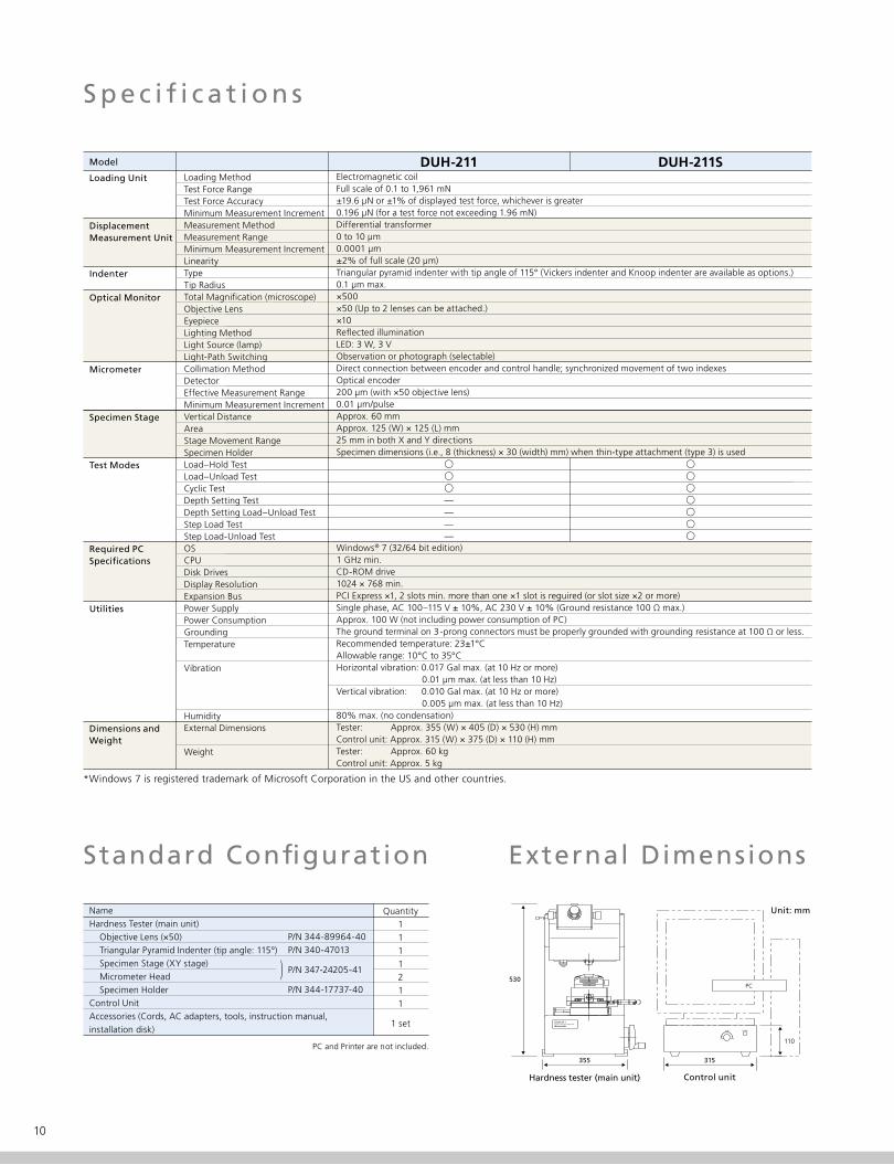
S p e c i f i c a t i o n s
Model
Loading Unit
DisplacementMeasurement Unit
Indenter
Optical Monitor
Micrometer
Specimen Stage
Test Modes
Required PCSpeci�cations
Utilities
Dimensions andWeight
Loading MethodTest Force RangeTest Force AccuracyMinimum Measurement IncrementMeasurement MethodMeasurement RangeMinimum Measurement IncrementLinearityTypeTip RadiusTotal Magni�cation (microscope)Objective LensEyepieceLighting MethodLight Source (lamp)Light-Path SwitchingCollimation MethodDetectorEffective Measurement RangeMinimum Measurement IncrementVertical DistanceAreaStage Movement RangeSpecimen HolderLoad–Hold TestLoad–Unload TestCyclic TestDepth Setting TestDepth Setting Load–Unload TestStep Load TestStep Load-Unload TestOSCPUDisk DrivesDisplay ResolutionExpansion BusPower SupplyPower ConsumptionGroundingTemperature
Vibration
Humidity External Dimensions
Weight
DUH-211 DUH-211SElectromagnetic coilFull scale of 0.1 to 1,961 mN±19.6 µN or ±1% of displayed test force, whichever is greater0.196 µN (for a test force not exceeding 1.96 mN)Differential transformer0 to 10 µm0.0001 µm±2% of full scale (20 µm)Triangular pyramid indenter with tip angle of 115° (Vickers indenter and Knoop indenter are available as options.)0.1 µm max.×500×50 (Up to 2 lenses can be attached.)×10Re�ected illuminationLED: 3 W, 3 VObservation or photograph (selectable) Direct connection between encoder and control handle; synchronized movement of two indexesOptical encoder200 µm (with ×50 objective lens)0.01 µm/pulseApprox. 60 mmApprox. 125 (W) × 125 (L) mm25 mm in both X and Y directionsSpecimen dimensions (i.e., 8 (thickness) × 30 (width) mm) when thin-type attachment (type 3) is used
Windows® 7 (32/64 bit edition)1 GHz min.CD-ROM drive1024 × 768 min.PCI Express ×1, 2 slots min. more than one ×1 slot is reguired (or slot size ×2 or more) Single phase, AC 100–115 V ± 10%, AC 230 V ± 10% (Ground resistance 100 Ω max.)Approx. 100 W (not including power consumption of PC)The ground terminal on 3-prong connectors must be properly grounded with grounding resistance at 100 Ω or less.Recommended temperature: 23±1°CAllowable range: 10°C to 35°CHorizontal vibration: 0.017 Gal max. (at 10 Hz or more) 0.01 µm max. (at less than 10 Hz)Vertical vibration: 0.010 Gal max. (at 10 Hz or more) 0.005 µm max. (at less than 10 Hz)80% max. (no condensation)Tester: Approx. 355 (W) × 405 (D) × 530 (H) mmControl unit: Approx. 315 (W) × 375 (D) × 110 (H) mmTester: Approx. 60 kgControl unit: Approx. 5 kg
*Windows 7 is registered trademark of Microsoft Corporation in the US and other countries.
Standard Con�guration
NameHardness Tester (main unit) Objective Lens (×50) Triangular Pyramid Indenter (tip angle: 115°) Specimen Stage (XY stage) Micrometer Head Specimen HolderControl UnitAccessories (Cords, AC adapters, tools, instruction manual, installation disk)
)
P/N 344-89964-40P/N 340-47013
P/N 347-24205-41
P/N 344-17737-40
Quantity1111211
1 set
External Dimensions
Unit: mm
PC530
355 315
110
Hardness tester (main unit)
PC and Printer are not included.
Control unit
10

O p t i o n a l A c c e s s o r i e s
Microscope images of the specimen surface can be displayed on the PC screen. Measure the size of indentations on the screen and save the images. Maximum magni�cation factor is ×2400 (when using a 17 monitor and an objective lens with a magni�cation factor of 50). This accessory can be used with computers designated by Shimadzu.
Length measurement kit, color: P/N 347-24778-44Length measurement kit, monochrome: P/N 347-24778-43
Length Measurement Kit (Color or Monochrome)
In the case that Active Vibration-Absorbing Bench is used this is select.W700 × D650 × H950 (mm)
Windbreak (Large type)P/N 347-24400-02
This case minimizes the in�uence of air disturbances, such as due to DUH tester exposure to air �ow or sound.W700 × D650 × H750 (mm)
WindbreakP/N 347-24400-01
Used for measuring hardness with the 700HMV micro Vickers. Used as a rough guide for Vickers hardness measurement.
Vickers Hardness Standard BlockP/N 340-06619-07
Objective Lens×100 objective lens P/N 344-89977-40×40 objective lens P/N 347-25400×20 objective lens P/N 344-89924-40×10 objective lens P/N 344-89941-40×40 objective lens with ultra-long operating distance P/N 344-89300-4140× objective lens with ultra-long operating distance. Improves contrast in the �eld-of-view.
This indenter, with a tip angle of 100°, has a smaller tip radius and makes smaller indentations than an indenter with a tip angle of 115°. Used for testing small-size specimens.
Triangular Pyramid Indenter with 100° Tip Angle
P/N 340-47011
γ
βα
Shape of indenter tip
α = β = γ = 100°
Used to obtain the correction factors required for the indenter when measuring the elastic modulus.
BK7 (Glass Test Piece)P/N 339-89207-14
The veri�cation in accordance with standard (ISO 6507-2) is done at the factory.Factory veri�ed for compliance with Vickers hardness test standards.Please order simultaneously with the DUH.
Measurement Kit for Vickers HardnessP/N 347-24449-01
Measurement Kit for Knoop HardnessP/N 347-24449-11
The veri�cation in accordance with standard (ISO 4545-2) is done at the factory.Factory veri�ed for compliance with Vickers hardness test standards.Please order simultaneously with the DUH.
Desk-Type Vibration Absorbing BenchP/N 344-04193-06
This bench with desk-type coil springs is recommended if the DUH-211/211S tester is used in areas that are subject to strong vibrations.
Slender Specimen HolderP/N 344-82943-40
This attachment is used to �rmly hold thin specimens with an outer diameter of 0.15 mm to 1.6 mm, such as sewing machine needles, watch shafts, thin-shaped medical equipment, wires, sintered wires, and nonferrous wires.
Used to digitally display the amount of stage movement (up to a maximum of 25 mm) in the front/back or left/right directions in 1 µm increments. (Photo shows this head attached to a stage.)
Micrometer Head (Digital Display)P/N 347-25447-12 (2 unit)
Disk-Type Vacuum Suction UnitP/N 344-86201-42
Used for 5 , 6 , and 8 wafers. (Air supply for suction must be separately prepared.)
This stage has a diameter of 125 mm and can rotate in the range ±5°.
Rotation StageP/N 344-82857-01
Used to adjust the microscope's magni�cation factor. Marked with scale graduations at 10 µm intervals.
Objective MicrometerP/N 046-60201-02
Installation Precautions Consider the following points when deciding on the installation location of the tester.
1. To minimize vibration:1) Install the tester in a location where �oor
vibration is minimal. Normally, place the tester on a vibration-absorbing bench.
2) Do not install the tester in a location where people requently walk by.
3) Do not install the tester near equipment that generates vibrations.
4) If possible, install the tester on the �rst �oor of a building.
5) Install the tester as far away as possible from streets, roads and railway tracks.
6) Do not perform testing if vibration-generating equipment (e.g., a crane) is being used nearby.
2. To minimize air drafts and sounds:1) Do not install the tester in locations that are
directly or indirectly subject to streams of air from air-conditioning equipment.
2) Use a windbreak during testing.3) Do not open or close nearby doors during testing.4) Do not install the tester near sound-generating equipment (e.g., telephones).
3. To ensure testing accuracy:Be especially careful when performing the following types of tests:• Tests involving test forces of 1 mN or less• Tests involving the measurement of changes for indentation depths of 0.05 µm or lessIn these cases, be sure to maintain the following conditions:• Temperature: No �uctuations greater than ±1°C.• Vibration: Refer to speci�cation table.
Active Vibration-Absorbing BenchP/N 344-04211-11: AC 120 VP/N 344-04211-12: AC 230 V
This bench is used together with a special mount and performs active vibration absorption over a wide range, from 0.7 Hz to 100 Hz.
DUH-211/211SDynamic Ultra Micro Hardness Testers 11

DU
H-211/211S
Example of Dynamic Ultra Micro Handness Tester DUH-211/211S Systems
Electric X–YStage System P/N 347-24625-41
• Stroke
• Resolution
• Drive method
* Compatible to electric Z system.
X-axis, Y-axis ±25 mm(There is the function that the slides 50 mm toward the X-axis.All stroke of X-axis are 100 mm)
0.001 mm
Ball screw actuated by stepping motor
High-TemperatureUnit System
P/N 347-24700-41 (50 Hz) 347-24700-42 (60 Hz)
• Temperature Setting Range
• Accuracy
• Total Magni�cation of Microscope
• Utilities
From 30°C above room temperature to 250°C(temperature control is possible at 50°C or higher)
Within ±2°C of set temperature
×400 (objective lens: ×40; eyepiece: ×10)
100V 50/60 Hz
* High-temperature systems are only available when ordering the main unit.
Micro Compression Testing Machine
MCT Series
This machine is used to measure the compressive strength of single particles (of diameter 1 µm or greater). The compressive strength of ceramics, plastics, pigments, food products, and pharmaceuticals can be measured at a particulate matter stage, providing data that is closely related to the �nal application of these substances.
• Loading Method
• Indenter
• Displacement Measurement• Optical Monitor
Electromagnetic force 9.807 mN to 1.961 N or 9.807 mN to 4.903 NDiamond, cone-shaped, 50-µmø diameterDifferential transformer 0 µm to 10 µm or 0 µm to 100 µmEquipped with ×500 microscope
Micro Hardness Tester
HMV-G21
This type of hardness tester automatically measures length using a built-in CCD camera. The automatic measurement function provides easy and worry-free measurements without human error. The innovative G-frame provides a broad work area, dramatically improves operability, and easily accommodates long samples or other samples with a large area.The automatic lens switching function automatically switches to the magni�cation appropriate for the given indentation size, which means anyone can operate the system accurately.
• Test Force Range
• Indentation Measurement Time• Equipped with revolving electric turret (HMV-G21T)
98.07 mN to 19.61 N(Optionally from 9.807 m)Approx. 0.3 sec.
Fully Automatic Micro Hardness Tester
HMV-G-FA
By including an automatic measurement function, an electric XYZ stage function, and an auto-focus function to a micro Vickers hardness tester used for evaluating the hardness of paint or plating coatings or surface-hardened layers, this automatic hardness tester is able to perform a continuous series of highly precise measurements automatically.
• Test Force Range
• Electric XY Stage
• Autofocus
98.07 mN to 19.61 N(Optionally from 9.807 m)Stroke: ±25 mmResolution: 0.001 mmApprox. 3 sec.
www.shimadzu.com/an/
Company names, product/service names and logos used in this publication are trademarks and trade names of Shimadzu Corporation or its af�liates, whether or not they are used with trademark symbol “TM” or “®”.Third-party trademarks and trade names may be used in this publication to refer to either the entities or their products/services. Shimadzu disclaims any proprietary interest in trademarks and trade names other than its own.
For Research Use Only. Not for use in diagnostic procedures. The contents of this publication are provided to you “as is” without warranty of any kind, and are subject to change without notice. Shimadzu does not assume any responsibility or liability for any damage, whether direct or indirect, relating to the use of this publication.
© Shimadzu Corporation, 2016
Printed in Japan 3655-11515-20ANS