dualsphysics in coastal engineering · 2017-06-21 · dualsphysics in coastal engineering dr...
TRANSCRIPT

DualSPHysics in Coastal Engineering
Dr Corrado AltomareUniversiteit Gent - Flanders Hydraulics Research, Belgium
2nd DualSPHysics Users Workshop, 6-7 December 2016
Dr Alex CrespoUniversity of Vigo, SPAIN

Outline of Presentation
DualSPHysics in coastal protection Wave generation & wave absorption
Wave-structure interaction
Coupling with wave propagation models
DualSPHysics in wave energy Wave interaction with floating bodies
Catenary moorings
Simulation of an Oscillating Water Column

Outline of Presentation
DualSPHysics in coastal protection Wave generation & wave absorption
Wave-structure interaction
Coupling with wave propagation models
DualSPHysics in wave energy Wave interaction with floating bodies
Catenary moorings
Simulation of an Oscillating Water Column

Motivation
The problems we are interested on:

Wave generation and wave absorption
The wave generation in DualSPHysics
mimics the conditions of physical wave facilities.
The wave-maker (piston, flap, flap with variable draft) consists of a rigid body
formed by boundary particles.
The motion of the wave generator is prescribed controlling its position (linear or
angular) at each instant of time.
AUTOMATIC WAVE GENERATION:• Regular & Irregular
• 1st and 2nd Order

Wave generation and wave absorption
PISTON-type wavemaker, REGULAR waves, 2nd Order
(Frigaard et al., 1993; Madsen, 1971)
𝜂 𝑥, 𝑡 =𝐻
2· 𝑐𝑜𝑠 𝜔𝑡 − 𝑘𝑥 + 𝛿 +
𝑘𝐻2
163𝑐𝑜𝑡ℎ 𝑘𝑑 3 − 𝑐𝑜𝑡ℎ(𝑘𝑑) 𝑐𝑜𝑠 2𝜔𝑡 − 2𝑘𝑥 + 2𝛿
𝑚1 =𝐻
𝑆0=
)2𝑠𝑖𝑛ℎ2(𝑘𝑑
sinh 𝑘𝑑 cosh 𝑘𝑑 + 𝑘𝑑
2𝑛𝑑 𝑜𝑟𝑑𝑒𝑟 𝑤𝑎𝑣𝑒 𝑡ℎ𝑒𝑜𝑟𝑦
𝐵𝑖𝑒𝑠𝑒𝑙 𝑡𝑟𝑎𝑛𝑠𝑓𝑒𝑟 𝑓𝑢𝑛𝑐𝑡𝑖𝑜𝑛 (1951)
𝑃𝑖𝑠𝑡𝑜𝑛 𝑑𝑖𝑠𝑝𝑙𝑎𝑐𝑒𝑚𝑒𝑛𝑡
)22sin(2
)(sinh
)cosh(3
32)sin(
2)(
1
3
2
0
t
mkd
kd
d
Ht
Ste

Wave generation and wave absorption
1. Define the wave spectrum (peak frequency, spectrum shape, etc.).
2. Define the frequency band width ∆f .
3. Determine frequency ωi, ai and δi (random between 0 and 2π) of each linear wave.
4. Apply Biesel:
5. Compose all the components into the time series of the piston displacement as:
In DualSPHysics:
a) JONSWAP and Pierson-Moskowitz
b) Phase seed
𝜔𝑖 = 2𝜋𝑓𝑖 𝑎𝑖 = 2𝑆𝜂(𝑓𝑖)∆𝑓 =𝐻𝑖2
𝐻𝑖𝑆0,𝑖=
)2𝑠𝑖𝑛ℎ2(𝑘𝑖ℎ
sinh 𝑘𝑖ℎ cosh 𝑘𝑖ℎ + 𝑘𝑖ℎ
𝑒(𝑡) =
𝑖=1
𝑁𝑆0,𝑖2co s(𝜔𝑖𝑡 + 𝛿𝑖)
PISTON-type wavemaker, IRREGULAR waves, 1st Order (Frigaard et al., 1993)

Wave generation and wave absorption
PISTON-type wavemaker, IRREGULAR waves, 2nd Order BOUND LONG waves
(Hughes, 1993)
Bound long waves (BLW) refer to the set-down of the water level that is generated by wave groups

Wave generation and wave absorption
This system can be either:
dissipative beach
a “sponge” area
applied at each time step
Passive wave absorption
),(0 dtxf vv
2
01
01),(
xx
xxdtdtxf

Wave generation and wave absorption
(Shaffer and Klopman , 2000)
𝜂𝑅(𝑡) = 𝜂𝐼(𝑡) −𝜂𝑆𝑃𝐻 (𝑡)
𝑈𝑅(𝑡) = 𝜂𝑅(𝑡) 𝑔 𝑑
𝑈𝐼(𝑡) = 𝜔𝑆02sin(𝜔𝑡 + 𝛿)
)𝑈𝐶 𝑡 + 𝑑𝑡 = 𝑈𝐼 𝑡 + 𝑈𝑅(𝑡
𝑒 𝑡 + 𝑑𝑡 = 𝑒 𝑡 + (𝑈𝐶 𝑡 + 𝑑𝑡 + 𝑈𝐶 𝑡 )𝑑𝑡
2
Reflected wave at 𝟒 ∗ 𝒉 from the piston
Velocity correction (uniform velocity field)
Theoretical wave maker velocity
Corrected wave maker velocity
Wave maker position at 𝒕 + 𝒅𝒕
FILTER
SERVO
+
Active wave absorption

Wave generation and wave absorption
Wave generation and wave absorption (passive and active) AWAS system in SPH models

Wave generation and wave absorption
Validation with theoretical results
Wave #1 Wave #2
Height H or Hm0 0.15m 0.10m
Period T or Tp 2.00s 3.00s
Depth d 0.66m 1.50m
Steepness s 0.033 0.010
Wavelength L 4.52m 10.22m
Wave #1 Wave #2
Wave gauges (WG) x=6.0, 6.5, 7.1m x=13.0, 14.0, 15.5m
Velocity gauge (VG) x=6.5m ; z=0.4m x=14m ; z=1m
Domain length (LX) 11m 26m
Test duration (tmax) 35s 50s

Wave generation and wave absorption
Validation with theoretical results: WAVE GENERATION
Wave #1

Wave generation and wave absorption
Validation with theoretical results: WAVE GENERATION
Wave #1

Wave generation and wave absorption
Validation with theoretical results: WAVE GENERATION
Wave #1

Wave generation and wave absorption
Validation with theoretical results: PASSIVE ABSORPTION
Wave #1

Wave generation and wave absorption
Validation with theoretical results: PASSIVE ABSORPTION
Wave #1
Damping
Cr Wave #1 Wave #2
Regular Irregular Regular Irregular
BEACH 11.4% 8.5% 8.4 % 5.7%
DAMPING 12.2% 8.6% 7.9 % 6.5%

Wave generation and wave absorption
Validation with theoretical results: ACTIVE ABSORPTION
Wave #1

Wave generation and wave absorption
Efficiency

Wave generation and wave absorption
Wave generation and wave absorption (passive and active) AWAS system in SPH models
WE NEED PASSIVE AND ACTIVE ABSORPTION TO MIMIC THE REAL SEA STATE CONDITIONS

Study of the run-up in an existing armour block sea breakwater
Coastal protection
DETAILED DESCRIPTION OF THE FLOWS !!!
Zeebrugge reference geometry (Belgium)
The size of the numerical simulation depends on the initial inter-particle distance
dp = 0.15 m => h = 0.225 m
The SPH domain contains 2,146,095 particles with 187,353 representing the boundaries

Study of the run-up in an existing armour block sea breakwater
Coastal protection
EquivalentSmooth
AntifersIrregular Pattern
AntifersRegular 1 Pattern
AntifersRegular 2 Pattern

Study of the run-up in an existing armour block sea breakwater
Coastal protection
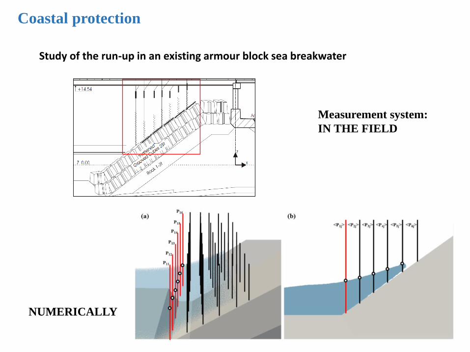
Study of the run-up in an existing armour block sea breakwater
Coastal protection
Measurement system:
IN THE FIELD
NUMERICALLY

Study of the run-up in an existing armour block sea breakwater
Coastal protection
Run=Ru/HComparison with experimental results

Coastal protection

Estimation of sea wave impact on coastal structures
Coastal protection
Wavemaker
Structure
3.2 m
0.8 m0.64 m
2.15 m
Berm
23.5 m
WG
Assessment of wave loadings on the dikes and storm
return walls in the Blankenberge Marina
Hm0=0.101m
Tp=2.683s

Coastal protection
Wavemaker displacement without and with Active Absorption
Comparison between numerical and experimental wave forces

Coupling with SWASH
Impacts of wave overtopping flows on coastal defenses and buildings
along the Flemish coast

Coupling with SWASH
Large domains
Long events
200 400 600 800 1000 1200 1400 1600 1800 2000 2200 24000
0.02
0.04
0.06
Layer thickness
time (s)
h (
m)
200 400 600 800 1000 1200 1400 1600 1800 2000 2200 2400-2
0
2
4
Layer speed
time (s)
u (
m/s
)
200 400 600 800 1000 1200 1400 1600 1800 2000 2200 2400-50
0
50
100
Instantaneous wave overtopping discharge
time (s)
q (
l/s/m
)
200 400 600 800 1000 1200 1400 1600 1800 2000 2200 2400
0
0.1
0.2
Free surface elevation at St.6 (toe of dike)
time(s)
eta
(m
)
Physical model
SWASH
Multi-scaled modeling

Coupling with SWASH
DualSPHysics SWASH
overlap

Coupling with SWASH

Coupling with SWASH
Sketch of the CIEM wave flume and locations of AWGs, ADVs and selected Coupling Points (CP)
Test case Htarget [m] Ttarget [s]
A 0.2 5.5
B 0.2 3.0
C 0.3 5.5
D 0.3 3.0

Coupling with SWASH
AWG free surface elevation: comparison between numerical and physical results
(CP1, test case B)

Coupling with SWASH
Horizontal and vertical velocity profiles (experimental in blue, numerical in red):
mean values and confidence intervals (CP1, test case D).

Coupling with SWASH
Improvements in time with different hybridisation points (domain sizes and runtimes)
WP CP1 CP2
DualSPHysics domain size 100% 78.42% 56.90%
Number of Particles 100% 62.89% 26.89%
Runtime 100% 70.49% 40.98%

Coupling with SWASH
Source Generation (under development)

Outline of Presentation
DualSPHysics in coastal protection Wave generation & wave absorption
Wave-structure interaction
Coupling with wave propagation models
DualSPHysics in wave energy Wave interaction with floating bodies
Catenary moorings
Simulation of an Oscillating Water Column

Wave interaction with floating bodies

Wave interaction with floating bodies
Floating body subjected to a wave packet is validated with experimental data
Hadzić et al., 2015

Wave interaction with floating bodies
Floating body subjected to a wave packet is validated with experimental data
Hadzić et al., 2015
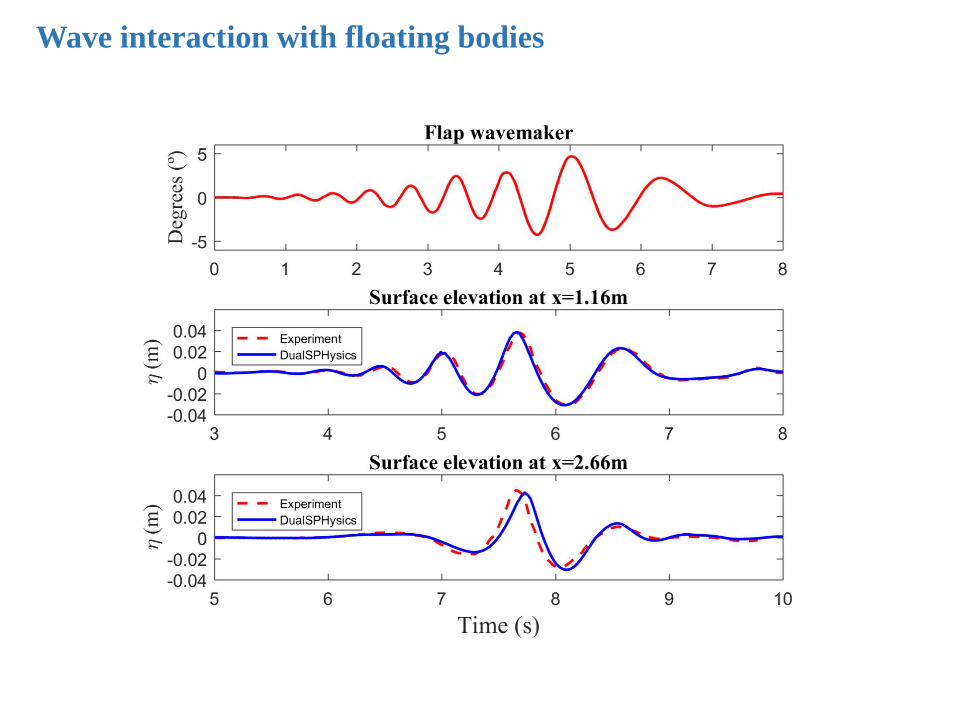
Wave interaction with floating bodies

Wave interaction with floating bodies

Floating moored objects
These objects are floating in the water and moored,
thus a proper formulation is needed and must be validated

Floating moored objects
𝑦 = 𝜉 cosh𝑥
𝜉
𝜉=1
𝜉=2
𝜉=3
The catenary function refers to the mathematical description
of a line with mass hanging between two points.
ξ is the form parameter
The maths from the work of Faltinsen (1993) is behind this implementation

Floating moored objects
Anchor pointAnchor point
(a)
(c)
(b)
(d)
Anchor pointAnchor point
(a)
(c)
(b)
(d)
FOUR different conditions for moorings are considered:
the resting chain, partially resting chain, partially extended chain and the fully extended chain
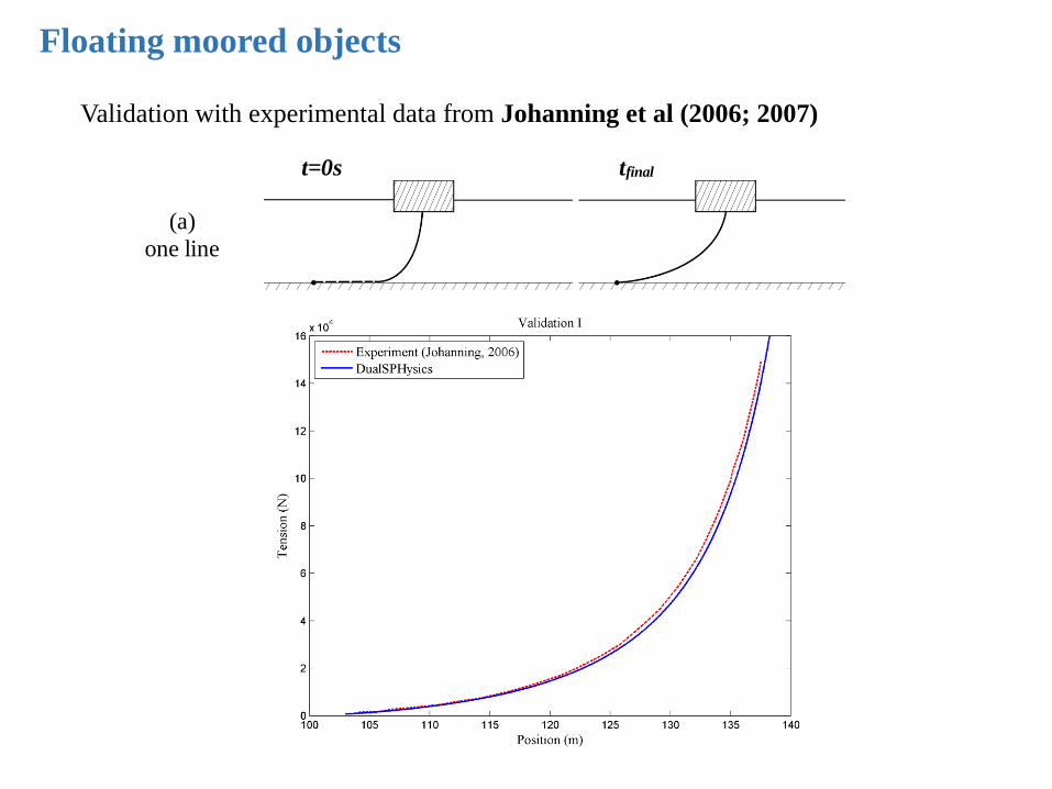
Floating moored objects
t=0s tfinal
(a)
one line
(b) two lines
Validation with experimental data from Johanning et al (2006; 2007)

Floating moored objects
t=0s tfinal
(b)
two lines
Validation with experimental data from Johanning et al (2006; 2007)

Floating moored objects

Floating moored objects

Floating moored objects

Floating moored objects
WE ARE NOW VALIDATION MOORINGS WITH MORE EXPERIMENTS


Design of OWC
NUMERICAL MODELLING
Hydrodynamic interaction between WECs and ocean waves
is a complex high order non-linear process
CFD models
Approximate Navier–Stokes
Linear approach
Time or frequency domain models
FAST AND EFFICIENT
LOW AMPLITUDE MOTIONS
Meshless
methods
Meshbased
methods
TIME CONSUMING
VIOLENT FLOWS
WAMIT
OpenFoam SPH

EXPERIMENT IN IH-CANTABRIA
The experiment (scale of 1/30) was carried out in the IH-Cantabria:
Laboratory wave flume (left) and chamber model (right).
Iturrioz, A., Guanche, R., Armesto, J.A., Alves, M.A., Vidal, C., Losada, I.J. 2014. Time-domain modeling of a
fixed detached oscillating water column towards a floating multi-chamber device, Ocean Engineering, 76, 65-74.
Design of OWC

EXPERIMENT IN IH-CANTABRIA
The experiment (scale of 1/30) was carried out in the IH-Cantabria wave flume.
The tank is 20.60 m long and the water depth was of 0.60 m.
A dissipative beach appeared at the end of the flume to avoid reflection.
Height
(H)
Period
(T)
Depth
(d)
Wavelength
(L)
Relative depth
(d/L)
Wave order
0.08 m 3.2 s 0.6 m 7.46 m 0.08 Stokes 2nd order
Wave conditions of the experiments in Iturrioz et al. (2014)
Iturrioz, A., Guanche, R., Armesto, J.A., Alves, M.A., Vidal, C., Losada, I.J. 2014. Time-domain modeling of a
fixed detached oscillating water column towards a floating multi-chamber device, Ocean Engineering, 76, 65-74.
Design of OWC

EXPERIMENT IN IH-CANTABRIA
Design of OWC

EXPERIMENT IN IH-CANTABRIA
Elevation inside the chamber:
Experiment vs Time-domain vs IHFoam vs DualSPHysics
2nd order: T=3.2s, H=0.08m, d=0.6m, L=7.46 m
Design of OWC

ONSHORE OWC IN MUTRIKU (SPAIN)
Design of OWC

ONSHORE OWC IN MUTRIKU (SPAIN)
OWC CHAMBER BREAKWATER
Cross section of Mutriku breakwater
Design of OWC

ONSHORE OWC IN MUTRIKU (SPAIN)
Cross section of Mutriku breakwater
Design of OWC

ONSHORE OWC IN MUTRIKU (SPAIN)
Real dimensions for DualSPHysics simulation
Design of OWC

ONSHORE OWC IN MUTRIKU (SPAIN)
Realistic wave conditions in the Cantábrico coast
Real dimensions for DualSPHysics simulation
Design of OWC
Height
(H)
Period
(T)
Depth
(d)
Wavelength
(L)
Relative d
(d/L)
Wave theory
Test M1 0.8 m 10 s 10 m 92.4 m 0.108 Stokes, 2nd order
Test M2 1.2 m 10 s 10 m 92.4 m 0.108 Stokes, 2nd order
Test M3 1.6 m 10 s 10 m 92.4 m 0.108 Stokes, 2nd order
Test M4 2.0 m 10 s 10 m 92.4 m 0.108 Stokes, 2nd order
Test M5 2.4 m 10 s 10 m 92.4 m 0.108 Stokes, 2nd order
Test M6 0.8 m 8 s 10 m 70.9 m 0.141 Stokes, 2nd order
Test M7 0.8 m 8.5 s 10 m 76.4 m 0.131 Stokes, 2nd order
Test M8 0.8 m 9 s 10 m 81.7 m 0.122 Stokes, 2nd order
Test M9 0.8 m 9.5 s 10 m 87.1 m 0.115 Stokes, 2nd order
Test M1 0.8 m 10 s 10 m 92.4 m 0.108 Stokes, 2nd order
Test M10 0.8 m 10 s 7.75 m 82.7 m 0.094 Stokes, 2nd order
Test M11 0.8 m 10 s 8.88 m 87.8 m 0.101 Stokes, 2nd order
Test M1 0.8 m 10 s 10 m 92.4 m 0.108 Stokes, 2nd order
Test M12 0.8 m 10 s 11.12 m 96.6 m 0.115 Stokes, 2nd order
Test M13 0.8 m 10 s 12.25 m 100.6 m 0.122 Stokes, 2nd order

ONSHORE OWC IN MUTRIKU (SPAIN)
WAVE PROPAGATION?? Test M5: H=2.4m T=10s in a long tank of constant depth
Elevation and orbital velocity: Theoretical vs DualSPHysics
Design of OWC

ONSHORE OWC IN MUTRIKU (SPAIN)
x=115m
OWC chamber
ACTIVE ABSORPTION?? Test M5: H=2.4m T=10s
Design of OWC
AWAS

ONSHORE OWC IN MUTRIKU (SPAIN)
Design of OWC

ONSHORE OWC IN MUTRIKU (SPAIN)
T with different HH=0.8m T=10s
H=1.6m T=10s
H=2.4m T=10s
H with different TH=0.8m T=8s
H=0.8m T=10s
H=0.8m T=12s
Different tidesH=0.8m T=10s
H=0.8m T=10s low
H=0.8m T=10s high
Elevation inside the Mutriku chamber
Design of OWC

ONSHORE OWC IN MUTRIKU (SPAIN)
Maximum amplitudes of the free-surface elevations
inside the OWC chamber of Mutriku for different wave conditions.
Design of OWC

NEW SPH FUNCTIONALITIES
- Wave generation (1st & 2nd order)
- Wave active absorption AWAS
- Fluid-driven objects
- Mooring lines
Design of OWC
OFFSHORE FLOATING OWC IN THE OPEN SEA

OFFSHORE FLOATING OWC IN THE OPEN SEA
The simulation of a floating OWC in open sea with SPH includes:
- Wave generation of regular waves with T=9s & H=1.8m.
- Passive wave absorption at the end of the tank with dissipative beach.
- AWAS system to generate a regular train that interacts with floating OWC
- Forces of catenary moorings are added to the total force of the floating structure
Design of OWC
AWAS BEACH
MOORINGS
Floating OWC

OFFSHORE FLOATING OWC IN THE OPEN SEA
Elevation inside the floating OWC chamber
Design of OWC

OFFSHORE FLOATING OWC IN THE OPEN SEA
Time histories of the motions of the floating OWC
(surge, sway and heave motion, and roll, pitch and yaw rotation).
Design of OWC

OFFSHORE FLOATING OWC IN THE OPEN SEA
Design of OWC

• Source Generation in combination with SWASH
• Multiphase: air+water
• Coupling with MoorDyn
Future developments
http://www.matt-hall.ca/moordyn/

• Coupling with MoorDyn
Future developments

• Source Generation in combination with SWASH
• Multiphase: air+water
• Coupling with MoorDyn
• Coupling with Multiphysics (next talk)
Future developments

• Coupling with Multiphysics (next talk)
Future developments

Thank you
Acknowledgements
• DualSPHysics team: all developers and contributors
• Special thanks to Ghent University and FHR
Website
Free open-source DualSPHysics code:
http://www.dual.sphysics.org