dual supervisory architecture for drift correction and ...ppayeur/smart/papers/i2mtc2012_2.pdf ·...
TRANSCRIPT
Dual Supervisory Architecture for Drift Correction and Accurate Visual Servoing in Industrial Manufacturing
Valentin Borsu and Pierre Payeur School of Electrical Engineering and Computer Science
University of Ottawa Ottawa, Canada
[vbors100, ppayeur]@uottawa.ca
Abstract—Pose and motion estimation techniques required to drive robotic manipulators involved in quality control in the automotive industry often encounter important limitations when applied on weakly textured panels moving in complex environments. Difficulties originate from the reduced performance of classical feature extraction, tracking and matching algorithms that heavily depend on the presence of rich textures over the objects. While maintaining a simple hardware architecture relying on passive stereoscopy, this paper proposes a supervisory approach for machine vision systems that overcomes the sensitivity of feature-based tracking to occlusions, photometric variations and ubiquitous appearances of factory associates in the field of view of the vision system. Furthermore, the drift accumulating with the tracking module is also corrected. Experimentation demonstrates the suitability of the proposed supervised pose and motion estimator for automated robotic marking of surface deformations over moving panels.
Keywords-visual servoing, pose and motion estimation, machine vision, sensor-based robotic navigation, industrial manufacturing.
I. INTRODUCTION
Continuous research efforts are invested in the development of robust and fault-tolerant techniques for several challenging tasks including robotic interaction with moving industrial objects. The implementation of these approaches has initiated a new era for industrial processes automation, ranging from assembly operations to critical quality control procedures. However, the transition from existing approaches, developed for robots acting on moving bodies [1, 2], to commercial autonomous systems experiences a dual barrier. While the lack of robust and objective methods for the evaluation of empirical performance represents an important issue [3], the difficulty of tracking industrial panels, which often suffer from a lack of unique features over their surfaces is even more challenging [1].
In order for a robotic arm to perform tasks on a moving panel, vision and range sensors must provide accurate and real-time data about the pose and motion of the object, whose surface appearance plays a central role. When considering quality control in the automotive industry, the target objects usually correspond to weakly textured automotive body panels, which are still unfinished at the stage of inspection. Therefore, the latter exhibit a very low number of sharp, distinctive features over their surfaces. The appearance of the panels,
along with the necessity of operating in real-time and without the existence of dedicated 3D CAD models, impose severe limitations, even for the most established computer vision tools available for pose and motion estimation (PME) which extensively rely on feature extraction [4, 5], tracking [6, 7], and matching [8]. For example, applying the SIFT scale-invariant feature transform [4] on scenes containing such weakly textured surfaces demonstrated poor repeatability and variability [9], leading to a degradation of the lifespan of the few features extracted throughout a tracking sequence [10]. As an alternative, Torr’s structure and motion toolkit [8], whose central component is a Maximum A Posteriori Sampling Consensus (MAPSAC) for matching features in the presence of outliers, also encounters severe limitations over weakly textured panels [10]. Since the set of matches contains a large number of outliers, the unicity property [9] of the feature matching process is severely compromised.
Weber and Malik [11] identified three classes of errors affecting the optical flow computation performed by the Lucas-Kanade (LK) feature tracker [6]. Systematic errors, related to cases where a large displacement is present in-between the processed frames, can be resolved through the adoption of a multi-scale representation of the tracking algorithm, using image pyramids [7]. Also, the failure of the brightness constancy assumption, resulting from occlusions or photometric variations, causes severe tracking errors. The optimization criterion proposed by Jin et al. [12], which relies on a hybrid geometrical and photometry model for characterizing the inter-frame motion, achieves robustness to photometric variations. However, this approach remains sensitive to occlusions and to strong changes in the intensity of the feature patches, produced by the appearance of different entities in the inspected scene. Finally, the cumulative errors in the motion prediction process must also to be taken into consideration, as they produce a drift of the features throughout the tracking history. This last type of error is apparent when a set of features needs to be tracked over a long period.
The objective of this research is to develop innovative hierarchical processing structures for the integration and adaptation of classical computer vision techniques within a real-time architecture to handle pose and motion estimation of automotive panels over long sequences. The solution described in the following sections builds upon previous
978-1-4577-1772-7/12/$26.00 ©2012 IEEE

achievements for a PME that includes a coarse-level supervisory layer [10] to provide an integrated solution for automated detection and robotic marking of surface deformations. The coarse-level supervisory structure provides extra robustness to the LK tracker in cases where brightness variations and occlusions occur. The current effort aims at also correcting the drift that accumulates with the tracking over long sequences by the combination of the coarse-level supervision strategy with a fine-level supervisory gate.
The proposed computational technique resolves the main limitations of state-of-the-art computer vision tools for cases where the objects of interest are weakly textured and exhibit free movements in complex industrial environments. Such operational conditions often lead to severe occlusions by a manipulator robot and to sporadic appearances of factory associates in the field of view of the vision sensors which must anyhow continue to track the object to ensure the integrity of the task.
The proposed supervised PME architecture differs from existing solutions that rely on multiple vision sensors, controlled backgrounds and 3D models of the industrial parts [1, 2] to provide timely-mannered, accurate and fault-tolerant visual servoing data to a robotic station. It rather addresses these constraints entirely from a software perspective while relying only on passive stereoscopy, which increases the flexibility of the strategy to operate under various conditions.
In the following sections, the experimental platform is described and the framework for the original dual supervisory architecture of the PME is introduced. The fine supervisory module, which addresses the limitations of the coarse supervisory level, is extensively described and experimentally validated under realistic industrial operation conditions for a robotic quality control application.
II. APPLICATION AND EXPERIMENTAL PLATEFORM The proposed quality control application combines an
automated defects detection system with a robotic station that handles the marking of deformations over automotive panels moving on an assembly line, with no human supervision beyond system configuration. A view of the experimental platform is shown in Fig. 1. The detection of surface deformations, which relies on the analysis of a 3D model of the panel acquired with a structured light sensor [13], is beyond the scope of this paper. Specific attention is provided to the dually supervised PME, which is the central component of the automated robotic system action on moving panels for marking the surface defects.
Different automotive panels, including car doors and fenders are tested, as they replicate the appearance of unfinished automotive panels at the stage of early manufacturing. The assembly line functions are provided by a 54cm sled system, driven by a separate motor at variable speeds.
The supervised PME relies on a calibrated stereoscopic sensor (SS), composed of two Point Grey Flea2 640x480 CCD cameras with 8.5mm lenses. A 44.5cm baseline is set between the cameras, as it offers adequate precision in reconstructing the sparse structure of the inspected parts. The panels are located at approximately 310cm from the acquisition system when traversing the inspection station.
Figure 1: Experimental platform for pose and motion evaluation.
III. SUPERVISED POSE AND MOTION ESTIMATOR The dual supervisory PME architecture, illustrated in Fig.
2, relies on a minimum set (typically 6 to 10) of macro-features (MFs), which are manually pre-selected over the structure of a given type of panels. The selection of the MFs is performed only once when configuring the visual servoing robotic station. Under mass production conditions, where a large number of the same panel must be inspected, the configuration represents a minor procedure and is easily performed with minimal training and knowledge about the operation of the inspection system. Such selected MFs are shown in Fig. 3a and 3b for two types of panels used in the experimentation. The dually supervised PME embeds automatic re-initialization of MFs each time a new automotive panel of the same type enters the inspection station [10]. As shown in Fig. 2, re-initialization of the MFs is triggered by a rigid body detection module, which informs the PME when the automotive part fully appears in both views of the SS.
Figure 2: Dual supervisory pose and motion estimation architecture.
After re-initialization, the MFs position information is stored in two topological structure buffers (TSBs) that are used by the supervisory system. The first buffer is populated with the Euclidean distances between each 2D MF and all the other MFs in the extracted set. The second buffer stores the relative X and Y displacements, expressed with respect to the image plane, between each MF and all the other MFs.
(a) (b)
Figure 3: Pre-selected MFs over the surface of: (a) a car door, (b) a fender.
After the re-initialization procedure, the MFs are tracked frame-by-frame, with a pyramidal LK tracker [6, 7], which is applied separately on both views of the SS. Given that the

MFs are stored in an indexed structure, the feature tracking process also provides the solution to the stereo matching. The data provided by the feature tracker, coupled with the calibration information of the SS, constitute the input to the motion estimation module, which computes the rigid transformation exhibited by the automotive part between successive pairs of frames.
The known limitations of the pyramidal LK tracker when applied on weakly textured panels that move in complex environments are addressed by the supervisory architecture. The latter is responsible for continuously monitoring and validating all MFs, along with their associated motion vectors and disparities. The objective of the coarse-level supervisory system is to correct the severe tracking errors generated by the LK tracker in case of occlusions, illumination changes and variations in the reflectance property of the automotive panels throughout the motion sequence. The coarse-level supervision builds upon the two TSBs described above, which offer a 2D signature of the tracked region. Apart from reliably correcting erroneous motion vectors, the coarse-level supervisory layer is also able to recover the MFs lost during the tracking. The only constraint of the coarse-level supervisory layer is related to the scaling effects exhibited by the moving panel. Changes in scaling of the panel as imaged by the SS need to be minimal over the entire tracking sequence, given that the two buffers are populated only once at the beginning of the tracking process. However, the limited field of view of the SS, which represents the width of the inspection station, imposes a relatively uniform distance between the vision sensor and the assembly line. The requirement is therefore easily satisfied under most configurations. An elaborate investigation of the LK tracker and improvements achieved with the coarse-level supervisory layer are presented in [10].
In addition, the drift accumulated with the pyramidal LK tracker must also be taken into consideration, in order to provide stable visual servoing data to the robotic marking process. For that matter, a supplementary fine-level supervisory layer is introduced in this paper. This new layer, shown in Fig. 2, further refines the precision of the feature tracking and matching processes, by correcting the drift accumulating during tracking. It also provides the dually supervised PME with the robustness required for cases where an assembly line contains curved sections that influence the motion of the automotive panel being inspected. The following section elaborates on the design of the fine-level supervisory layer.
IV. FINE-LEVEL SUPERVISORY LAYER The objective of this hierarchical structure is to monitor
and validate the feature tracking and matching processes of the PME at every iteration, imposing time-efficiency and precision to the visual servoing data provided to the robotic marking station. A comparative basis is initially established with Sampson’s first-order correction which aims at improving the validation of the epipolar geometry.
A. Sampson’s first-order correction Hartley and Zisserman [14] have studied in detail
Sampson’s first-order approximation, which has beneficial effects in correcting feature matches, such that the epipolar constraint is more precisely validated, assuming that the
fundamental matrix of the SS is accurately known or estimated. However, if at a given point over the motion sequence, the MFs are already displaced, due to drifting, the corrections provided by Sampson’s approximation are not able to eliminate the drift accumulation. These corrections will only enforce the validation of the epipolar geometry with no constraint related to the ground-truth position of the MFs over the inspected panels, which needs to be consistent with the locations shown in Fig. 3. Although Sampson’s correction has beneficial effects from a pair-wise perspective over the pose estimation problem, the cumulative tracking errors recursively affect the motion estimations, which cause inaccuracies in the robotic guidance. For these reasons, a more robust monitoring procedure must be embedded in the fine-level supervisory layer in order to successfully account for the small, but significant errors which appear during the tracking of the MFs set over a significant number of frames [11, 12].
B. Fine-level supervisory design The immediate consequence of the drift associated with the
use of the pyramidal LK tracker is on the lifetime of the MFs. As a result, some MFs experience a re-initialization of their tracking process, leading to the inter-frame feature correspondence operation being applied over a shorter time span. The integration time of the computed trajectory is therefore decreased, which results in apparently good tracking performance for that particular feature, although it might no longer belong to the physical structure of the inspected object. Given that the pose and motion estimation constitutes the basis of the robotic interaction with the moving panel, the erroneous information that is transferred to the robotic marking station corrupts the attitude of the robot end-effector with respect to the deformations that need to be marked. The significant amount of drift that can accumulate from the tracking process, even after the addition of the coarse-level supervisory layer, is illustrated in Fig. 4. The locations of the MFs are shown in the 1st (considered as ground-truth, GT) and the last (20th) frame grabbed by the left stereo-camera (CamL), which are separated by only 40 seconds. Almost all MFs suffer from considerable drift throughout the motion period, especially those highlighted in zoomed areas.
Figure 4: 1st and 20th processed frames, showing the effect of drift
accumulating with the pyramidal LK tracker.
To alleviate these problems, the fine-level supervisory layer consists of an original validation method that assigns a signature to the limited set of 3D MFs, to aid in the final refinement of the feature tracking process. When compared to the coarse-level supervisory gate [10], the fine-level validation
technique privileges the testing performed in 3D, due to the scaling effects which affect the MFs topological structure in the image plane. For that reason and in order to validate the generality of the proposed supervision technique, the sled motion is no longer constrained to a plane that is almost perpendicular to the principal axis of the SS. This movement introduces a scaling effect in the image planes, as the car door gets closer to the acquisition system during its motion cycle.
The proposed procedure for assigning a signature to the MFs is inspired by an overlapping error methodology. Starting from the initial 3D structure of the MFs, corresponding to the GT frame, the primary goal is to verify how the subsequent 3D structures of the MFs, recovered over the tracking process, differ from their GT distribution. However, the metrics by which the GT and the current 3D MFs structures can be reliably compared are critical. Identifying the amount of displacement that needs to be applied to the GT rigid structure, in order to compare it to the current 3D MFs, involves relying on the motion estimation data, which builds upon a least-squares technique, proposed by Arun et al. [15]. The latter is strongly influenced by the precision of the feature tracking and matching results.
The proposed solution for identifying the MFs affected by drift relies on a normalization procedure [14], known as “pre-conditioning”. It consists in transforming the 3D coordinates of the MFs, defined with respect to the world reference frame, here CamR, to a normalized space, NS . This normalization involves two steps. First, the 3D MFs are centered about their centroid:
~
i i MFMF MF MF, i 0, , N 1= − = − (1) where NMF is the number of MFs and the centroid is
MFN 1
iMF i 0
1MF MFN−
=
⎛ ⎞= ⎜ ⎟⎝ ⎠ ∑
. Then, the mean 3D Euclidean distance
from the origin to the centered macro-features MFs, ~
iMF , d
is computed, and the normalized macro-features, iMF , are obtained:
~
i i2MF MFd⎛ ⎞= ⎜ ⎟⎝ ⎠
(2)
in a manner in which the average Euclidean distance from the origin is equal to 2 .
By transferring the 3D topological structure of the MFs, recovered throughout the tracking, to the normalized space, the identification of the drifted MFs can be achieved, with no need to predict the location of the 3D GT structure at subsequent frame extraction times. While the first step of the normalization procedure removes the translation component, which affects the 3D MFs throughout the motion cycle, the rotation component is still present in the set of normalized MFs. It needs to be taken into account in order to result in a consistent validation technique. By introducing a pre-processing step, to remove the rotation component between the two data sets, the proposed solution acquires robustness for cases where the assembly line is curved, causing the panel to get closer to the SS, and to exhibit rotations around its Yo axis, as represented in Fig. 1. The inverse of the rotation matrix, extracted from the estimated rigid transformation relating the GT 3D structure with the current 3D structure, is applied to the
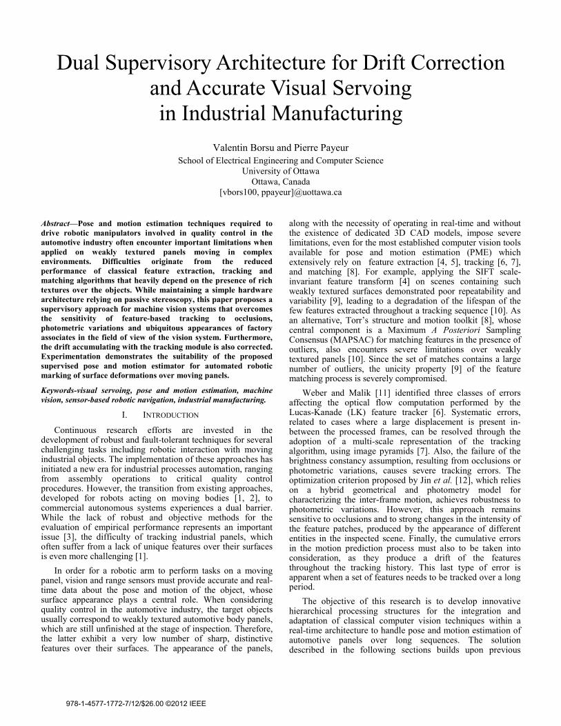
normalized 3D MFs belonging to the current frame. The normalized 3D structures for the GT and the 20th frame (after removal of the rotation component) are illustrated in Fig. 5.
Figure 5: 3D structures of the door MFs in NS (1st, 20th frame).
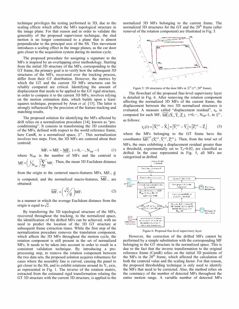
The flowchart of the proposed fine-level supervisory layer is detailed in Fig. 6. After removing the rotation component affecting the normalized 3D MFs of the current frame, the displacement between the two 3D normalized structures is evaluated. A measure called “displacement residual”, rδ, is computed for each MF, i i i iMF (X ,Y , Z ), i=0,···, NMF-1, in NS , as follows:
GT GT GTi i i i i ir (i) X X Y Y Z Zδ = − + − + − (3)
where the MFs belonging to the GT frame have the coordinates GT GT GT GT
i i i iMF (X ,Y , Z ) . Then, from the total set of MFs, the ones exhibiting a displacement residual greater than a threshold, experimentally set to Tδ=0.02, are classified as drifted. In the case represented in Fig. 5, all MFs are categorized as drifted.
Figure 6: Proposed fine-level supervisory layer.
However, the correction of the drifted MFs cannot be performed by a simple substitution with the corresponding MF belonging to the GT structure in the normalized space. This is due to the fact that the inverse transformation to the original reference frame (CamR) relies on the initial 3D positions of the MFs in the 20th frame, which affected the calculation of both the centroid value and the scaling factor. For that reason, the proposed thresholding technique is only used to identify the MFs that need to be corrected. Also, the method relies on the constancy of the number of detected MFs throughout the entire motion range. A variable number of detected MFs

would result in different values for the centroid and the scaling factor, preempting a consistent comparison. However, experimentation with the coarse-level supervisory layer demonstrated that lost MFs can reliably be recovered under most industrial manufacturing conditions regardless of the occlusions caused by the robot arm or the workers moving in the inspected scene [10].
When the number of MFs with a displacement residual smaller than the threshold, Tδ, is greater or equal to three (the cardinality test), their associated 3D coordinates (defined in
NS and forming the Spass set of size Npass) in the current frame need also to be tested for non-colinearity. This validation test is performed in NS and evaluates:
( ) ( ) ( )2 2 2
ij i j i j i j
ijk ijk ijk ij ijk ik ijk jk
d X X Y Y Z Z ,i j
p (p d )(p d )(p d ), i j k
⎧ = − + − + − ≠⎪⎨⎪Α = − − − ≠ ≠⎩
(4)
where ijd is the Euclidean 3D distance between any two MFs
belonging to Spass, ijkΑ is the area subtended by any three MFs
of Spass, while ( )ij ik jkijk
d d dp 2
+ += is the semi-perimeter
formed by the three MFs, according to Heron’s formula. In order for the extracted MFs to form a non-degenerated configuration, the maximum distance between any two MFs, as well as the maximum area between any three selected MFs have to verify the conditions:
max MFsij min_ Dist min
max MFsijk min_ Area min
d T 1.5 D
T 1.5 A
⎧ ≥ = ⋅⎪⎨
Α ≥ = ⋅⎪⎩ (5)
where MFsminD is the minimum distance between any two GT
MFs in NS , and MFsminA is the minimum area subtended by any
three MFs in the GT structure defined in NS . The coefficient appearing in eq. (5) was selected experimentally.
Once the extracted set of non-drifted normalized MFs, Spass, has passed the cardinality and non-colinearity tests, as depicted in Fig. 6, these MFs, as defined with respect to CamR, along with their corresponding GT MFs, are used for estimating the rigid transformation exhibited by the panel between the GT and the current view. Upon the calculation of the (R, T) pair [10], the MFs classified as drifted are corrected based on their 3D location in the GT frame and the newly estimated rigid transformation, as follows:
GTCorrectedMF R MF T.= ⋅ + (6)
The full calibration of the SS makes possible the back-projection of the corrected MFs on the image plane, and thus, the refinement of the 2D topological structure of the MFs. The proposed refinement can be categorized as an a posteriori correction, as it relies on consistent 3D data in order to adapt the MFs 2D topological structure to the scaling effects or the changes in orientation exhibited by the panel throughout a general motion period. Once the topological structure of the MFs has been refined in the image plane, the TSBs, introduced in Section III, are re-populated. This update procedure also has beneficial effects in the correction phase of the coarse-level supervisory system. By implementing the fine-level supervision, the drift accumulating with the pyramidal LK
tracker is bounded, preempting the propagation of erroneous pose and motion estimations to the robotic marking station.
A special case that must be analyzed corresponds to situations where the extracted set of MFs with a displacement residual smaller than Tδ has either a cardinal inferior to three, or the extracted MFs form a degenerate configuration. In these circumstances, as illustrated in Fig. 6, the MF with the smallest displacement residual is automatically extracted. Based on the data stored in the buffer of relative displacements, the rest of the MFs are recovered in both views. Subsequently, with the purpose of further refining these recovered MFs, Sampson’s first-order correction is applied. The refined feature matches, which validate the epipolar geometry, after the Sampson’s first-order correction, are then used to update the TSBs.
V. EXPERIMENTAL VALIDATION Figure 7a shows the MFs belonging to the 20th frame,
when the fine-level supervision gate is added to the PME, under the same experimental settings that generated the results shown in Fig. 4. Due to the integration of the fine-level supervision, which also updates the TSBs used by the coarse-level supervisory gate, only MF9, as indexed in Fig. 3a, and marked with black in Fig. 7a, is detected as drifted from the GT structure, as opposed to the initial results in Fig. 4. The large number of drifted MFs shown in Fig. 4 is definitely an effect of the lack of correction to the drifted MFs, as well as the single update of the TSBs throughout the motion cycle. Figure 7b shows the substantial reduction achieved on the displacement residuals, rδ, associated to the MFs structure in the 20th frame after the integration of the fine-level supervisory system and the correction of MF9. Moreover, the displacement residuals associated to the MFs in the 20th frame after the correction performed by the fine-level supervisory system are all below the imposed displacement threshold Tδ. Figure 7c shows the MFs structure in NS , before and after the incorporation of the fine-level supervisory layer. Similar to the reduced displacement residuals, the new normalized structure, in green, resembles more the GT distribution of the MFs, in black, which maintain their positions over the surface of the car door panel.
The complete supervisory system, embedding the coarse-level and the proposed fine-level validation and correction layer was tested on 80 running scenarios involving various movements of the robot and people entering the field of view of the SS, as well as different positions and orientations of the sled system with respect to SS, characterized by θYo∈[-30o, 30o], and ΔZo∈[-45cm, 45cm]. The correction and recovery of the motion vectors was successful in all tested scenarios and the data transferred to the robotic marking operation accurate enough to reliably mark all deformations. Figure 8 illustrates the corrected/recovered motion vectors from four processed frames acquired by CamL over the tracking sequence, during which the manipulator robot (Fig. 8a) or people (Fig. 8b and 8c), or both the robot and people (Fig. 8d) are present in the view of the SS.
In Fig. 8 the motion vectors provided by the pyramidal LK tracker are represented in red and are affected by severe errors due to the occlusions caused by the manipulator robot or the people. The motion vectors corrected or recovered by the coarse-level supervisory system are drawn in black, and white,

respectively. Furthermore, the motion vectors refined via the fine-level supervisory layer are represented in green and are tagged with a white rectangle and zoomed. By inspecting Fig. 8 it can be noticed that all the refined MFs accurately point to the regions highlighted in Fig. 3, independently of the increased complexity of the monitored scene, or the selected type of automotive panel.
(a) (b)
(c)
Figure 7: (a) 20th frame with fine-level supervision, (b) displacement residuals in the 20th frame and, (c) 3D structures in NS , with and without fine-level
supervision.
(a) (b)
(c) (d) Figure 8: Processed frames in cases where: (a) the manipulator robot, or (b-c)
people, or (d) the robot and people are present in the scene.
VI. CONCLUSION The problem of pose and motion estimation over weakly
textured industrial panels, moving in complex environments, was addressed in this paper. With the objective of making a high-level supervised pose and motion estimation framework more accurate and robust to complex industrial environments, an innovative fine-level supervisory layer was introduced. The proposed approach exploits the topological structure of a limited number of MFs in 2D and 3D and is readily integrated in the validation and monitoring processes of feature tracking to compensate for significant drifting effects when employed over long tracking sequences.
Beyond an efficient correction of the drift accumulating over the tracking period, the experimental evaluation demonstrated the suitability of the dual supervised pose and motion estimator to realistic situations in which an object’s motion exhibits curved displacements or the field of view of the vision sensor is sporadically occluded by the manipulator robot or perturbed by factory associates. The performance demonstrated by the supervisory layer supported its successful integration into an automated robotic system for performing surface deformations marking on moving panels, while relying only on passive stereoscopic vision.
REFERENCES [1] G.N. DeSouza and A.C. Kak. “A subsumptive, hierarchical and
distributed vision-based architecture for smart robotics”, IEEE Trans. on Systems, Man and Cybernetics- B, vol. 34(5), pp. 1988-2002, 2004.
[2] L. Davis, D. DeMenthon, T. Bestul, S. Ziavras, H.V. Srinivasan, M. Siddalingaiah, and D. Harwood, “Robot acting on moving bodies (RAMBO): Interaction with tumbling objects”, Technical Report – Center for Automation Research, University of Maryland, 1989.
[3] T. Chang, T. Hong, M. Shneier, G. Holguin, J. Park, and R.D. Eastman, “Dynamic 6DOF metrology for evaluating a visual servoing system”, Performance Metrics for Intelligent Systems Workshop, Gaithersburg, MD, pp. 173-180, 2008.
[4] D. Lowe, “Distinctive image features from scale-invariant keypoints”, Intl. Journal of Computer Vision, vol. 60(2), pp. 91-110, 2004.
[5] J. Shi and C. Tomasi, “Good features to track”, IEEE Conf. on Computer Vision and Pattern Recognition, Seattle, WA, pp. 593-600, 1994.
[6] B.D. Lucas and T. Kanade, “An iterative image registration technique with an application to stereo vision”, DARPA Image Understanding Workshop, pp. 121-130, 1981.
[7] J.–Y. Bouguet, “Pyramidal implementation of the Lucas Kanade feature tracker – description of the algorithm”, [on-line], http://robots.stanford.edu/cs223b04/algo_tracking.pdf
[8] P.H.S. Torr, “A structure and motion toolkit in Matlab”, Microsoft Research Technical Report MSR-TR-2002-56.
[9] É. Vincent and R. Laganière, “An empirical study of some feature matching strategies”, Intl. Conf. on Vision Interface, Calgary, AB, pp. 139-145, 2002.
[10] V. Borsu and P. Payeur, “Supervised pose and motion estimation over weakly textured industrial objects”, IEEE Intl Symposium on Robotic and Sensors Environments, pp. 202-207, Montréal, QC, Sep. 2011.
[11] J. Weber and J. Malik, “Robust computation of optical flow in a multi-scale differential framework”, Intl. Journal of Computer Vision, vol. 14:67-81, 1995.
[12] H. Jin, P. Favaro, and S. Soatto, “Real-time feature tracking and outlier rejection with changes in illumination”, IEEE Intl Conf. on Computer Vision, Canada, pp. 684-689, 2001.
[13] A. Yogeswaran and P. Payeur, “Features Extraction from Point Clouds for Automated Detection of Deformations on Automotive Body Parts”, IEEE Intl Workshop on Robotic and Sensors Environments, pp. 122-127, Lecco, Italy, 2009.
[14] R. Hartley and A. Zisserman, Multiple view geometry in computer vision, Cambridge University Press, UK, 2000.
[15] K.S. Arun, T.S. Huang, and S.D. Blostein, “Least-squares fitting of two 3-D point sets”, IEEE Trans. on Pattern Analysis and Machine Intelligence, vol. 9(5), pp. 698-700, 1987.