dual-material minimum weight structures fabrication using
TRANSCRIPT
Dual-Material Minimum Weight Structures Fabrication Using Ultrasonic Consolidation
Obielodan J.O1 and Stucker B.E
2*
1Mechanical and Aerospace Engineering Department, Utah State University, Logan, UT 84322
2Industrial Engineering Department, University of Louisville, Louisville, KY 40292
Abstract
The multi-material capability of additive manufacturing (AM) processes has created
opportunities for structural designs that would otherwise be impossible. This work involves the
development of a methodology for fabricating dual-material minimum-weight structures using
ultrasonic consolidation (UC). Sample structures were designed, fabricated and tested for load
carrying capabilities. Analyses of results show that dual-material minimum weight structures
made of Al3003/MetPreg® and Al3003/Ti composite material members can withstand
significantly higher strain energy densities up to the point of failure than similar structures made
of Al 3003 alone. This is an indication that UC can be effectively used to fabricate multi-material
structures for real life applications.

1 Introduction
Research on the fabrication of multi-material structures using different additive
manufacturing (AM) processes has accelerated in recent years. AM processes have the potential
for flexible variation of materials and microstructures, both in continuous and discrete fashion in
addition to their capabilities for complex geometry structures. New uses of some advanced
materials are being discovered because of the ability to combine them with other materials in
AM fabricated structures. Also, some of the materials that would otherwise be difficult to
combine in conventional processes are being processed (Cohen et al., 2006; Malone et al., 2004;
Liu and DuPont 2003; Griffith et al., 1997; Arcaute et al., 2009; Janaki Ram et al., 2007;
Obielodan et al., 2010B). This ability to deposit function specific materials where they are
needed in a structure further revolutionizes engineering structure design and material usage. One
of the driving forces is the economic use of costly advanced materials that are prescribed to be
deposited just where they are functionally required in a structure. The application of these
capabilities is diverse, ranging from medical to aerospace, automobile, nuclear and others.
Potential applications of multi-material structures fabricated using AM processes have
been demonstrated. Arcaute et al., 2009, used stereolithography (SL) for the fabrication of multi-
material scaffolds with spatially controlled characteristics for tissue engineering applications.
Also, Wicker et al., 2004, fabricated complex multi-material hydrogel constructs for nerve
regeneration and guided angiogenesis applications. Meso and macro scale multi-material
structures have also been fabricated using SL (Jae-Won Choi et al. 2009 and Inamdar et al.
2006).

Objet Geometries Limited commercialized the 3D printing of dissimilar material end use
products using polymer materials (www.growit3d.com/services/multi-material-polyjet). Objet’s
ConnexTM
machines jet multiple materials simultaneously to fabricate multi-material structures.
Different laser powder metal deposition processes have been used to deposit multi-
material structures. Examples include gradient structures (Griffith et al., 1997, Liu and DuPont,
2003), surface cladding with corrosion and wear resistant materials for machinery (Foroozmehr
et al., 2009) and medical implants applications (Janaki Ram and Stucker, 2008). Both 3D
printing and laser powder deposition processes have capabilities for continuous material
variation as well as discrete material domains in fabricated multi-material structures.
Ultrasonic consolidation has been demonstrated to have the capabilities for multi-material
structures fabrication. This capability was demonstrated by Janaki Ram et al., 2007B, in their
work in which copper, brass, nickel, inconel 600, AISI 347 stainless steel, stainless steel AISI
304 wire mesh, MetPreg®
, and aluminum alloy 2024 were each welded to aluminum alloy 3003-
H18. Domack and Baughman, 2005, investigated the capability of UC to fabricate graded
titanium and nickel alloy multi-material structures. Additionally, ultrasonic welding has been
successfully used to weld metals to a polymer matrix composite (Kruger et al., 2004). Obielodan
et al., 2010B, further demonstrated UC multi-material capabilities by welding different
combinations of molybdenum, tantalum, titanium, copper, silver, nickel, MetPreg®, aluminum
alloys 1100, 3003, 6061 and boron powder. Also, the shear strengths of titanium/aluminum
ultrasonically bonded foils were characterized by Obielodan et al., 2009.
Ultrasonic consolidation, described more fully elsewhere (White, 2003 and Obielodan et
al., 2010A), is a low temperature process that combines ultrasonic welding and additive
manufacturing technology. Multi-material structures fabricated using UC characteristically have
discrete material domains as opposed to the continuous material variation that is obtainable with
laser powder deposition processes and 3D printing. The process has the potential for fabricating
structures for applications in systems subjected to mechanical loading. In this study, a
methodology for fabricating multi-material structures using UC was developed. UC structures
with a single material are relatively easy to fabricate when compared to multi-material
fabrications, as foils can be automatically fed.
Multi-material minimum weight Michell structures (Dewhurst, 2001; Dewhurst, 2005;
Selyugin, 2004 and Michell, 1904) represent one of the categories of structures that can be
geometrically and materially complex to fabricate using conventional processes. They are made
of multiple, thin members that are preferably made from light weight materials with high specific
strength and stiffness. Such structures are readily applicable to aerospace and automotive
industries, where there is continuous emphasis on higher strength and lower weight structures for
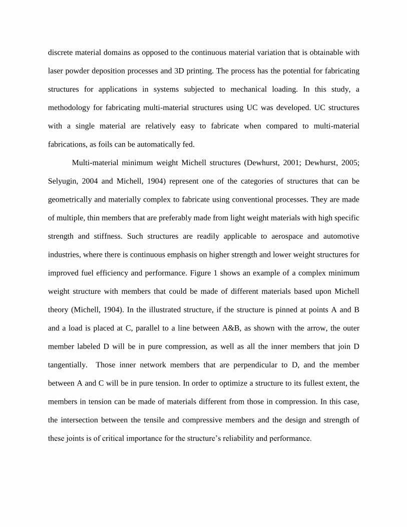
improved fuel efficiency and performance. Figure 1 shows an example of a complex minimum
weight structure with members that could be made of different materials based upon Michell
theory (Michell, 1904). In the illustrated structure, if the structure is pinned at points A and B
and a load is placed at C, parallel to a line between A&B, as shown with the arrow, the outer
member labeled D will be in pure compression, as well as all the inner members that join D
tangentially. Those inner network members that are perpendicular to D, and the member
between A and C will be in pure tension. In order to optimize a structure to its fullest extent, the
members in tension can be made of materials different from those in compression. In this case,
the intersection between the tensile and compressive members and the design and strength of
these joints is of critical importance for the structure’s reliability and performance.
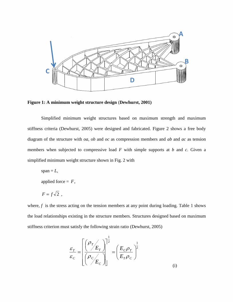
Figure 1: A minimum weight structure design (Dewhurst, 2001)
Simplified minimum weight structures based on maximum strength and maximum
stiffness criteria (Dewhurst, 2005) were designed and fabricated. Figure 2 shows a free body
diagram of the structure with oa, ob and oc as compression members and ab and ac as tension
members when subjected to compressive load F with simple supports at b and c. Given a
simplified minimum weight structure shown in Fig. 2 with
span = L,
applied force = ,F
2fF ,
where, f is the stress acting on the tension members at any point during loading. Table 1 shows
the load relationships existing in the structure members. Structures designed based on maximum
stiffness criterion must satisfy the following strain ratio (Dewhurst, 2005)
2
12
1
CT
TC
C
C
T
T
C
T
E
E
E
E
(i)
A
B
D
C
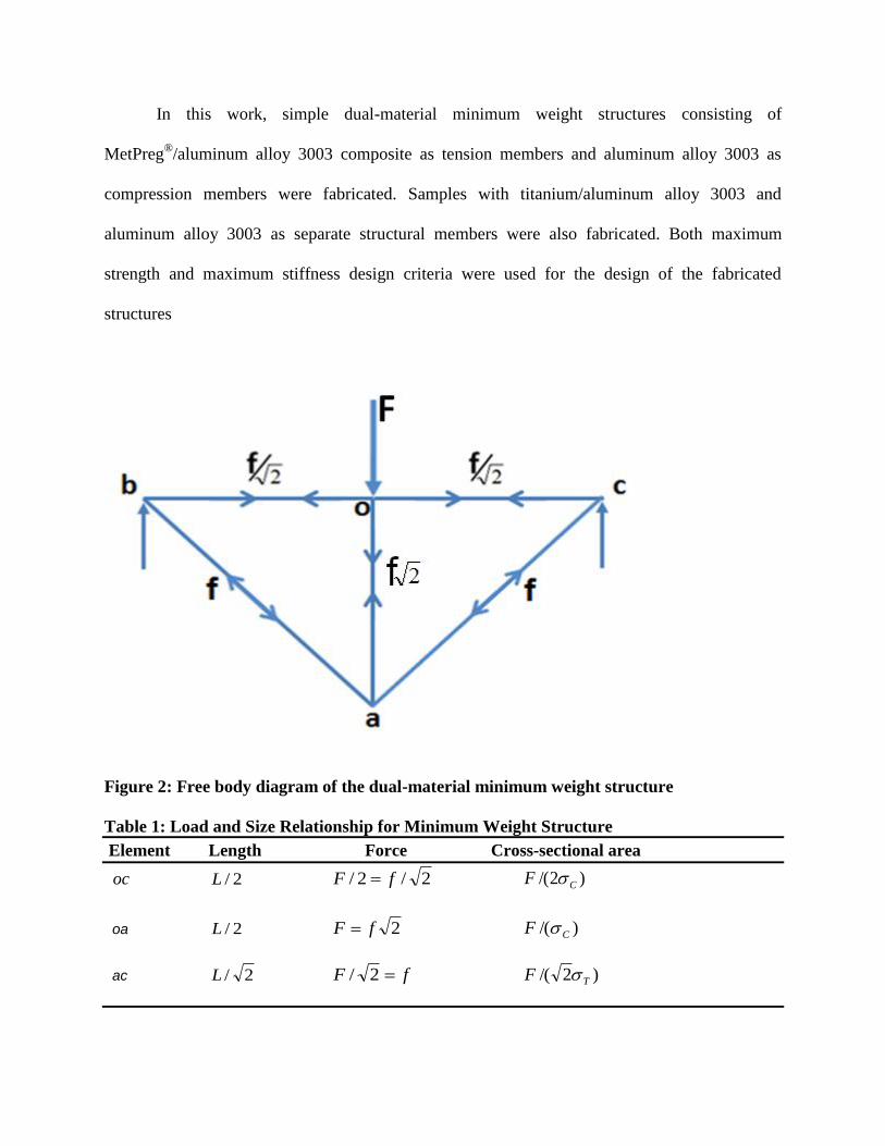
In this work, simple dual-material minimum weight structures consisting of
MetPreg®/aluminum alloy 3003 composite as tension members and aluminum alloy 3003 as
compression members were fabricated. Samples with titanium/aluminum alloy 3003 and
aluminum alloy 3003 as separate structural members were also fabricated. Both maximum
strength and maximum stiffness design criteria were used for the design of the fabricated
structures
Figure 2: Free body diagram of the dual-material minimum weight structure
Table 1: Load and Size Relationship for Minimum Weight Structure
Element Length Force Cross-sectional area
oc 2/L 2/2/ fF )2/( CF
oa 2/L 2fF )/( CF
ac 2/L fF 2/ )2/( TF

2 Experimental Work
A Solidica FormationTM
ultrasonic consolidation machine was used for all the
fabrications in this work. During typical operation, the machine uses an automatic foil feeding
mechanism, but foil materials can be fed manually when it is necessary. The parts were made on
aluminum alloy 3003-H18 substrate materials of 355 x 355 x 12 mm size, mounted on a heat
plate. Foil materials of aluminum alloy 3003-H18, MetPreg® and CP titanium were used for the
fabricated structures. The structures are composed of tension and compression members. The
tension members carry simple tensile loads while the compression members carry simple
compressive loads when a three-point load is applied as illustrated in Fig. 2. One set of the
structures consist of MetPreg®/Al3003 composite tension members and Al3003 compression
members. The other set was made of titanium/Al3003 composite tension members and Al3003
compression members. Both maximum stiffness and maximum strength minimum weight
structure design criteria were used for each material combination. Thus, for MetPreg®/Al3003
composite and Al3003 material combination, the two criteria were used to design structures
having different member sizes. The same criteria were applied for the titanium/Al3003 and
Al3003 material combination. Three structures were fabricated using each criteria and material
combination.
A third set of structures were ultrasonically consolidated exclusively with Al 3003-H18
foil material using the dimensions of the MetPreg®/Al 3003 material minimum weight structures.
Another set of structures were fabricated using wrought Al 3003 H-18, having the same base
material as the Al 3003 foil used. These last sets of structures were fabricated as single material
copies of the shape and sizes of the MetPreg® and titanium reinforced dual-material structures

described above. All the single material structures were fabricated for the sole purpose of
comparing their load carrying capabilities with those of the dual-material structures. The major
comparison factor is the strain energy densities of the structures at failure.
For the purpose of analysis and discussion in this work, the structures have been named
as follows. All structures designed based upon maximum strength design criterion or single
material copies of such designs have their labels hyphenated with “STR”. Similarly, those
designed based upon maximum stiffness criterion or their single material copies have their labels
hyphenated with “STF”. Thus, MetPreg®/Al 3003 dual-material structures designed based on
maximum strength criterion are labeled Met-STR, while structures of the same materials
designed based on maximum stiffness criterion are labeled Met-STF. Corresponding structures
designed based on Ti/Al 3003 materials are labeled Ti-STR and Ti-STF. The single material
direct copies of Met-STR and Met-STF structures ultrasonically consolidated using Al 3003 foils
are correspondingly labeled Al-STR and Al-STF. Also, those machined out directly from Al
3003-H18 plate as single material structure copies of Met-STR and Met-STF are correspondingly
labeled W-Al-MSTR and W-Al-MSTF, while copies of Ti-STR and Ti-STF are respectively
labeled W-Al-TSTR and W-Al-TSTF. The sizes of the members of the fabricated structures are
shown in Table 2.
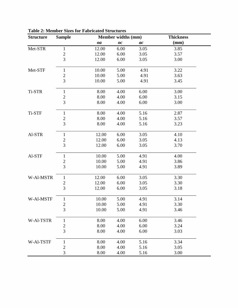
Table 2: Member Sizes for Fabricated Structures
Structure Sample Member widths (mm) Thickness
oa oc ac (mm)
Met-STR 1 12.00 6.00 3.05 3.85
2 12.00 6.00 3.05 3.57
3 12.00 6.00 3.05 3.00
____________________________________________________________
Met-STF 1 10.00 5.00 4.91 3.22
2 10.00 5.00 4.91 3.63
3 10.00 5.00 4.91 3.45
____________________________________________________________
Ti-STR 1 8.00 4.00 6.00 3.00
2 8.00 4.00 6.00 3.15
3 8.00 4.00 6.00 3.00
____________________________________________________________
Ti-STF 1 8.00 4.00 5.16 2.87
2 8.00 4.00 5.16 3.57
3 8.00 4.00 5.16 3.23
____________________________________________________________
Al-STR 1 12.00 6.00 3.05 4.10
2 12.00 6.00 3.05 4.13
3 12.00 6.00 3.05 3.70
____________________________________________________________
Al-STF 1 10.00 5.00 4.91 4.00
2 10.00 5.00 4.91 3.86
3 10.00 5.00 4.91 3.89
____________________________________________________________
W-Al-MSTR 1 12.00 6.00 3.05 3.30
2 12.00 6.00 3.05 3.30
3 12.00 6.00 3.05 3.18
____________________________________________________________
W-Al-MSTF 1 10.00 5.00 4.91 3.14
2 10.00 5.00 4.91 3.30
3 10.00 5.00 4.91 3.46
____________________________________________________________
W-Al-TSTR 1 8.00 4.00 6.00 3.46
2 8.00 4.00 6.00 3.24
3 8.00 4.00 6.00 3.03
____________________________________________________________
W-Al-TSTF 1 8.00 4.00 5.16 3.34
2 8.00 4.00 5.16 3.05
3 8.00 4.00 5.16 3.00
Four different machine codes were developed using Initial Graphics Exchange
Specification (IGES) 3-D model files for each of the dual material structures. This became
necessary as the UC machine needed to operate in an unconventional sequence characterized by
interruptions while changing from one file to the other because of the different materials used.
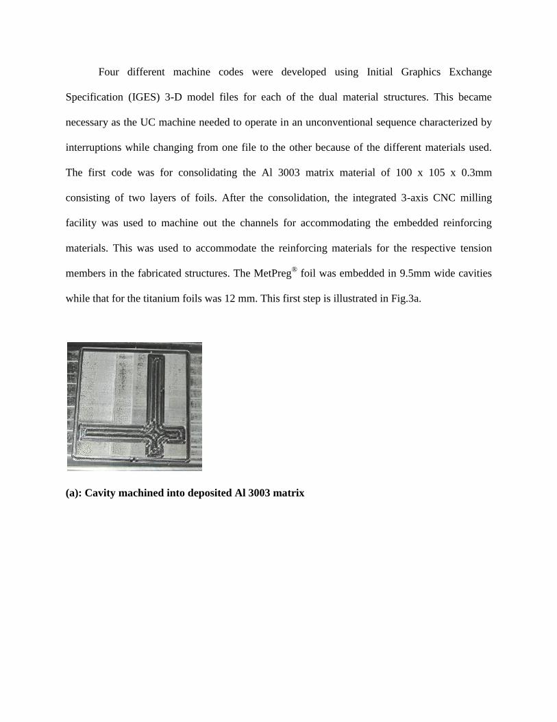
The first code was for consolidating the Al 3003 matrix material of 100 x 105 x 0.3mm
consisting of two layers of foils. After the consolidation, the integrated 3-axis CNC milling
facility was used to machine out the channels for accommodating the embedded reinforcing
materials. This was used to accommodate the reinforcing materials for the respective tension
members in the fabricated structures. The MetPreg®
foil was embedded in 9.5mm wide cavities
while that for the titanium foils was 12 mm. This first step is illustrated in Fig.3a.
(a): Cavity machined into deposited Al 3003 matrix
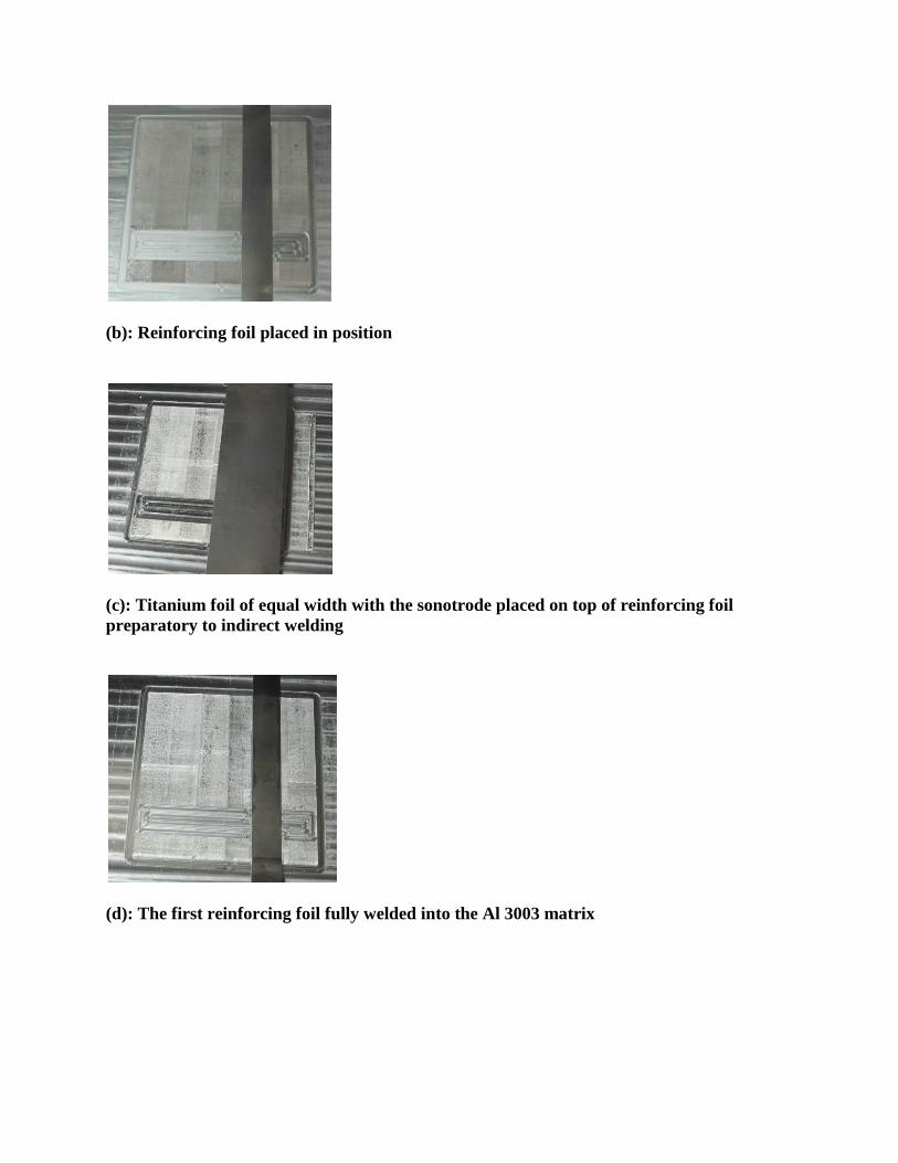
(b): Reinforcing foil placed in position
(c): Titanium foil of equal width with the sonotrode placed on top of reinforcing foil
preparatory to indirect welding
(d): The first reinforcing foil fully welded into the Al 3003 matrix
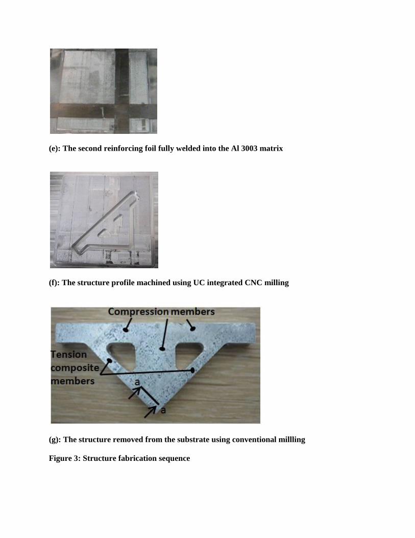
(e): The second reinforcing foil fully welded into the Al 3003 matrix
(f): The structure profile machined using UC integrated CNC milling
(g): The structure removed from the substrate using conventional millling
Figure 3: Structure fabrication sequence

The second and third machine codes were used to weld the reinforcing material that is
sandwiched with Al 3003 foils in alternate layers to make the composite tension members in
each of the structures. In the respective structures, the reinforcing materials serve to reinforce the
Al 3003 matrix foils in the tension members. The composite reinforcing foils were put in place
one at a time and welded indirectly by placing a 25mm width titanium foil between it and the
welding sonotrode as shown in Figs. 3b to 3e. The indirect welding was to prevent the sonotrode
from having direct contact with the softer Al 3003 matrix material because of the required high
welding amplitude applied for the reinforcing materials. Direct welding can destroy the Al 3003
matrix material at the high welding amplitude. The structures’ constituent materials were welded
using different sonotrode vibration amplitudes as determined in earlier work by Obielodan et al.,
2010B. Table 3 shows the compositional, hardness and dimensional details of the materials used
while Table 4 shows the welding parameters applied for their consolidation. The mechanical and
physical properties of the materials are shown in Table 5.
Table 3: Nominal Compositions, Crystal Structures and Hardness of Materials used
(Obielodan et al., 2010B)
Material Composition Crystal Structure Micro- Thickness
at UC Hardness
Temperature (Hv) (μm)
Al alloy 3003 H18 Al-1.2Mn-0.12Cu FCC 80 150
Titanium Ti-0.59Fe-0.38Mn HCP 185 70
MetPreg® Al2O3 Short Fiber - 600 200
Al matrix reinforced tape
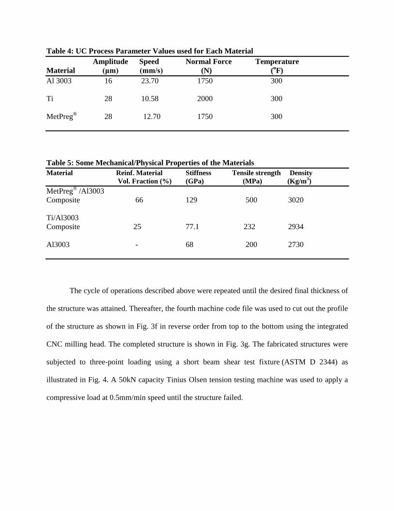
Table 4: UC Process Parameter Values used for Each Material
Amplitude Speed Normal Force Temperature
Material (μm) (mm/s) (N) (oF)
Al 3003 16 23.70 1750 300
Ti 28 10.58 2000 300
MetPreg®
28 12.70 1750 300
Table 5: Some Mechanical/Physical Properties of the Materials
Material Reinf. Material Stiffness Tensile strength Density
Vol. Fraction (%) (GPa) (MPa) (Kg/m3)
MetPreg® /Al3003
Composite 66 129 500 3020
Ti/Al3003
Composite 25 77.1 232 2934
Al3003 - 68 200 2730
The cycle of operations described above were repeated until the desired final thickness of
the structure was attained. Thereafter, the fourth machine code file was used to cut out the profile
of the structure as shown in Fig. 3f in reverse order from top to the bottom using the integrated
CNC milling head. The completed structure is shown in Fig. 3g. The fabricated structures were
subjected to three-point loading using a short beam shear test fixture (ASTM D 2344) as
illustrated in Fig. 4. A 50kN capacity Tinius Olsen tension testing machine was used to apply a
compressive load at 0.5mm/min speed until the structure failed.

Figure 4: Structure under test using a 3-point bend test fixture
2.1 Metallographic Studies
Small samples cut from the intersecting joints of the composite members as well as at
their joints with the matrix material at the top of the structures were mounted and polished
according to standard metallographic procedures. They were observed under optical microscope.
Fractographic studies were also carried out on fractured surfaces of the structures.
3 Results and discussion
3.1 Microstructures
Micrographs of section a-a in Fig. 3g at the intersection joints of representative structures
are shown in Fig. 5 below. Figure 5a shows the side and end views of reinforcing MetPreg®
foils
for the left and right hand side tension members respectively of the structure shown in Fig. 3g.
MetPreg® foils for the left hand side tension member have their foils stretching through the
length of the member in alternate layers. At the other layers, shorter reinforcing foils are seen
with abutting joints with those of the right hand side tension member (that is, those with their end
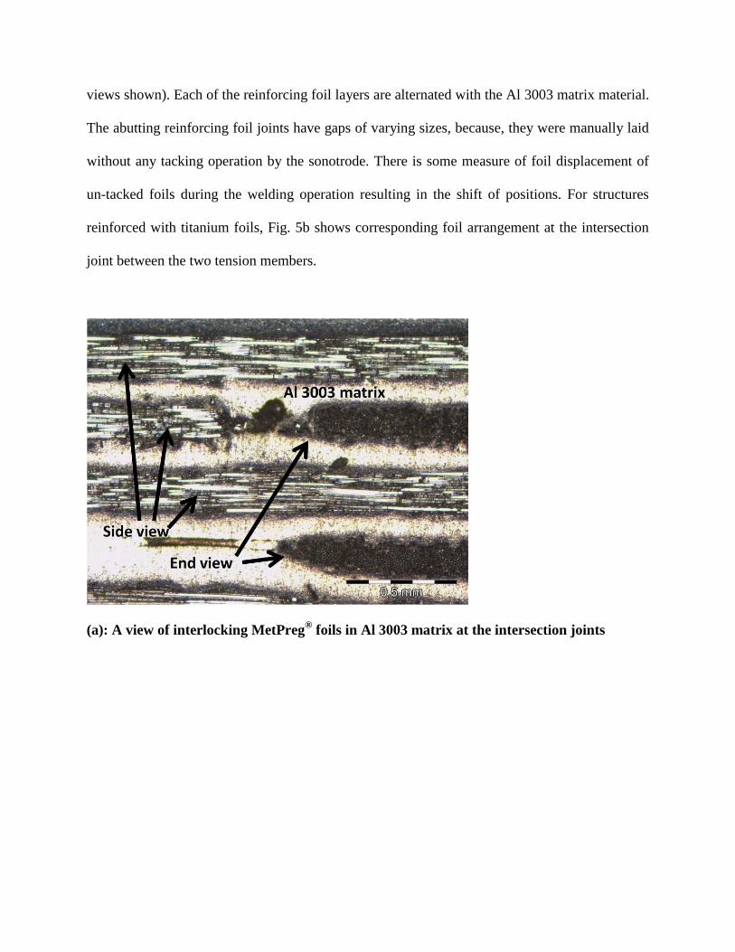
views shown). Each of the reinforcing foil layers are alternated with the Al 3003 matrix material.
The abutting reinforcing foil joints have gaps of varying sizes, because, they were manually laid
without any tacking operation by the sonotrode. There is some measure of foil displacement of
un-tacked foils during the welding operation resulting in the shift of positions. For structures
reinforced with titanium foils, Fig. 5b shows corresponding foil arrangement at the intersection
joint between the two tension members.
(a): A view of interlocking MetPreg® foils in Al 3003 matrix at the intersection joints
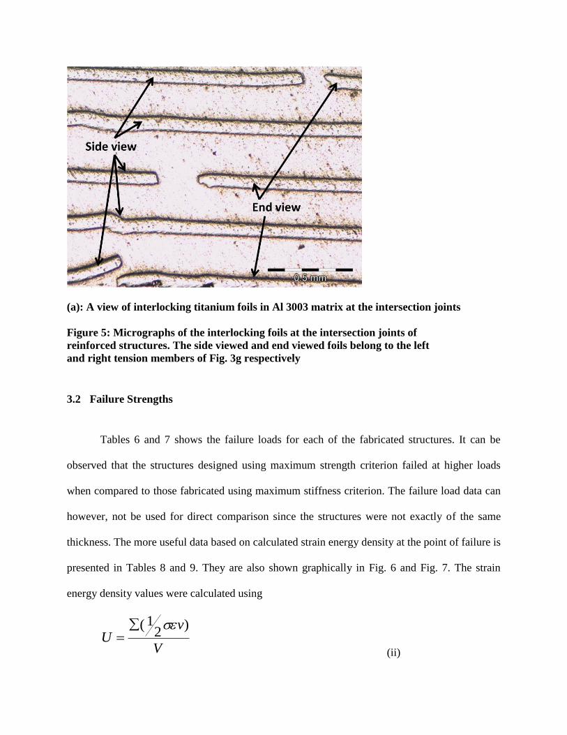
(a): A view of interlocking titanium foils in Al 3003 matrix at the intersection joints
Figure 5: Micrographs of the interlocking foils at the intersection joints of
reinforced structures. The side viewed and end viewed foils belong to the left
and right tension members of Fig. 3g respectively
3.2 Failure Strengths
Tables 6 and 7 shows the failure loads for each of the fabricated structures. It can be
observed that the structures designed using maximum strength criterion failed at higher loads
when compared to those fabricated using maximum stiffness criterion. The failure load data can
however, not be used for direct comparison since the structures were not exactly of the same
thickness. The more useful data based on calculated strain energy density at the point of failure is
presented in Tables 8 and 9. They are also shown graphically in Fig. 6 and Fig. 7. The strain
energy density values were calculated using
V
vU
)2
1(
(ii)

Where,
U = strain energy density for the structure
σ = stress in each member at the point of failure
ε = strain in each member at the point of failure
v = volume of each member
V = total structure volume
The stress σ in each member at the point of failure was calculated by normalizing the
resolved load (based on Table 1 relationships) with respect to cross-sectional area. With the
stress obtained, the strain ε was calculated using the stiffness value of each structure member.
The strain energy density data show that for structures of the same material combination,
those designed based on maximum strength criterion generally have higher load carrying
capacities than those designed based on maximum stiffness criterion. It is only in the case of Al-
STR and Al-STF, ultrasonically consolidated using Al 3003 matrix material that structures based
on maximum stiffness yielded higher average strain energy density.
Table 6: Failure Load (N) Data for MetPreg®/Al 3003 Based Structures
Sample 1 2 3
Met-STR 5190 4760 4140
Met-STF 4060 5020 4720
Ti-STR 3890 3760 4120
Ti-STF 3210 3360 3500
Al-STR 3120 3060 2530
Al-STF 4010 3840 3760

Table 7: Failure Load (N) Data for Ti/Al 3003 Based Structures
Sample 1 2 3
Ti-STR 3890 3760 4120
Ti-STF 3210 3360 3500
W-Al-STR 3200 3000 2730
W-Al-STR 2340 2230 2320
Table 8: Strain Energy Density (N/mm2) Data for MetPreg
® Based Structures
Sample 1 2 3 Average
Met-STR 1.72E+05 1.67E+05 1.79E+05 172585.4
Met-STF 1.208E+5 1.45E+05 1.43E+05 136266.67
Al-STR 9.77E+04 8.02E+04 68289.06 82068.39
Al-STF 1.07E+05 8.64E+04 9.93E+04 97500
W-Al-STR 1.22E+5 1.11E+5 1.12E+5 115062
W-Al-STF 1.01E+5 9.69E+4 9.49E+4 97583
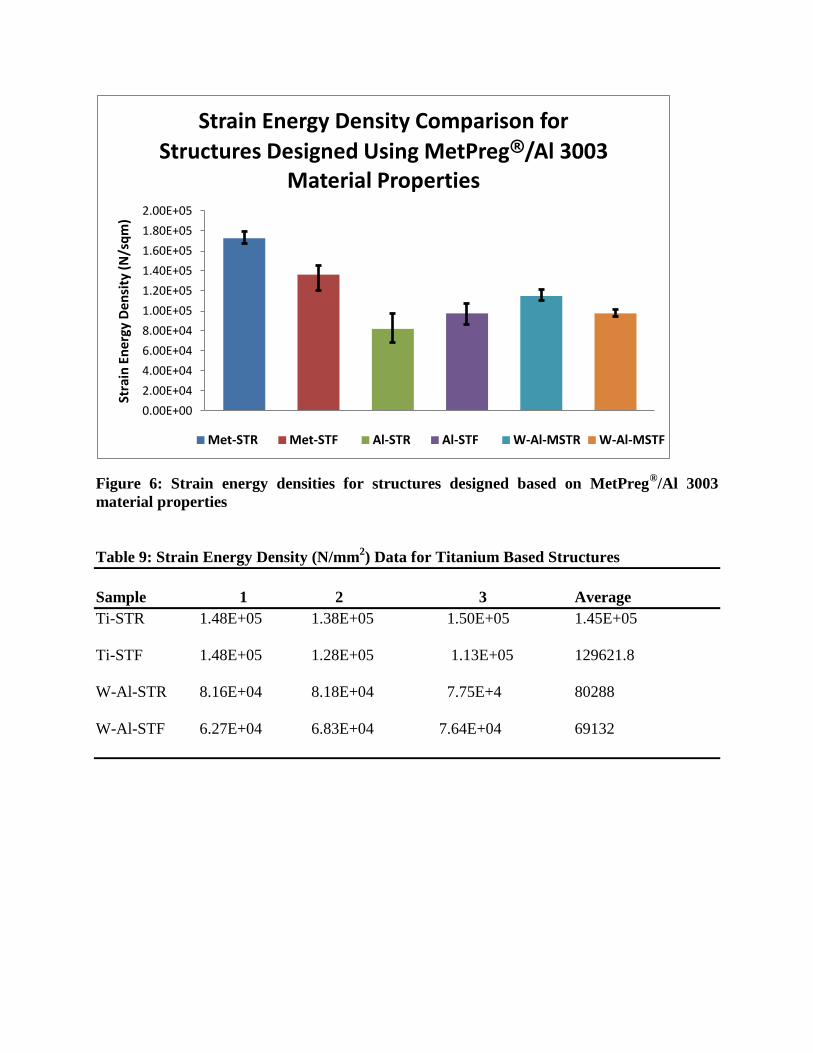
Figure 6: Strain energy densities for structures designed based on MetPreg®/Al 3003
material properties
Table 9: Strain Energy Density (N/mm2) Data for Titanium Based Structures
Sample 1 2 3 Average
Ti-STR 1.48E+05 1.38E+05 1.50E+05 1.45E+05
Ti-STF 1.48E+05 1.28E+05 1.13E+05 129621.8
W-Al-STR 8.16E+04 8.18E+04 7.75E+4 80288
W-Al-STF 6.27E+04 6.83E+04 7.64E+04 69132
0.00E+00
2.00E+04
4.00E+04
6.00E+04
8.00E+04
1.00E+05
1.20E+05
1.40E+05
1.60E+05
1.80E+05
2.00E+05
Stra
in E
ner
gy D
en
sity
(N
/sq
m)
Strain Energy Density Comparison for
Structures Designed Using MetPreg®/Al 3003 Material Properties
Met-STR Met-STF Al-STR Al-STF W-Al-MSTR W-Al-MSTF

Figure 7: Strain energy densities for structures designed based on Ti/Al 3003 material
properties
3.3 Statistical Analysis of the Strain Energy Density
The results of the strain energy densities presented above were analyzed statistically
using SAS 9.1 to verify whether or not their differences are significant. The experiment was a
two way factorial design with three replicates. The analyses combine the results of the
MetPreg®/Al3003 and Ti/Al3003 based structures all in one. Structure design criteria and
material used were the two fixed factors used for the analyses. For the purpose of this statistical
analysis, alphabetical letters were assigned to groups of experimental units based on the material
used as follows: A = Met-STR and Met-STF; B = Ti-STR and Ti-STF; C = Al-STR and Al-STF;
D = W-Al-MSTR and W-Al-MSTF; and E = W-Al-TSTR and W-Al-TSTF. Thus, material as a
factor comprise five levels while the design as a factor comprise two levels 1 and 2
0.00E+00
2.00E+04
4.00E+04
6.00E+04
8.00E+04
1.00E+05
1.20E+05
1.40E+05
1.60E+05
Stra
in E
ner
gy D
en
sity
(N
/Sq
m)
Strain Energy Density Comparison for Structures Designed Using Ti/Al 3003 Material Properties
Ti-STR Ti-STF W-Al-TSTR W-Al-TSTF

corresponding to structures designed based on maximum strength and maximum stiffness
respectively.
The result of the analysis shows that the data satisfies the assumption of approximate
normality and homoscedasticity. Analysis of variance (ANOVA) in Table 10 shows that the two
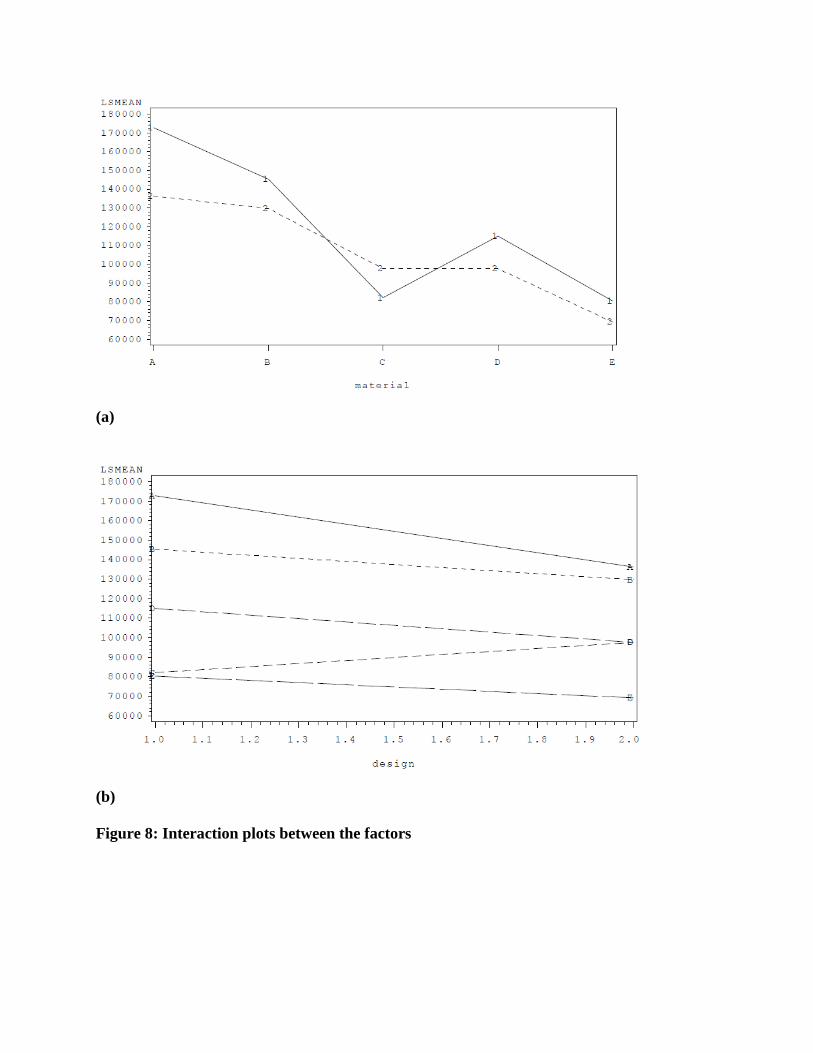
factors and their interactions have significant effects on the response variable. Using factor-level
comparison in the least square means (LSMEANS) table (that is, Table 11 below) and the
interaction plots in Fig. 8, it is evident that the difference of means between Met-STR and Met-
STF is statistically significant. Met-STR and Ti-STF also have significantly different means.
However, the difference between the means of Met-STR and Ti-STR is marginally insignificant.
Between Ti-STR and Ti-STF as well as between Met-STF and Ti-STF there is no significant
difference of mean strain energy density.
Comparing each of the reinforced structures with the un-reinforced ones, Met-STF and
W-Al-MSTR have statistically insignificant different means, although the former yielded higher
average strain energy density. Also, Ti-STF and W-Al-MSTR have statistically insignificant
different means, although the former yielded higher average strain energy density. Apart from
these two cases, all reinforced structures have significantly different mean strain energy densities
when compared with the single material structures. Post hoc means analysis data in Table 12 for
the individual factors shows that structures designed based upon maximum strength criterion
have significantly higher average strain energy density than those designed based upon
maximum stiffness criterion. Also, all the material categories have statistically significant
different average strain energy densities with MetPreg® reinforced materials yielding the highest
value.

From this analysis, it can be inferred that UC fabricated structures with appropriate
reinforcement leads to significant improvement of their load carrying capability compared to
fabrications with the matrix materials only. Although MetPreg® reinforced structures performed
better than titanium reinforced ones with corresponding design criteria, Ti can be considered as a
good reinforcement material. This is because the Ti volume fraction of 25% was considerably
lower than the 60% volume fraction of MetPreg® in the same matrix material. The higher cost of
MetPreg® makes titanium a good alternative, although the former has higher specific strength
than the latter.
Table 10: Analysis of Variance of the Experimental Data
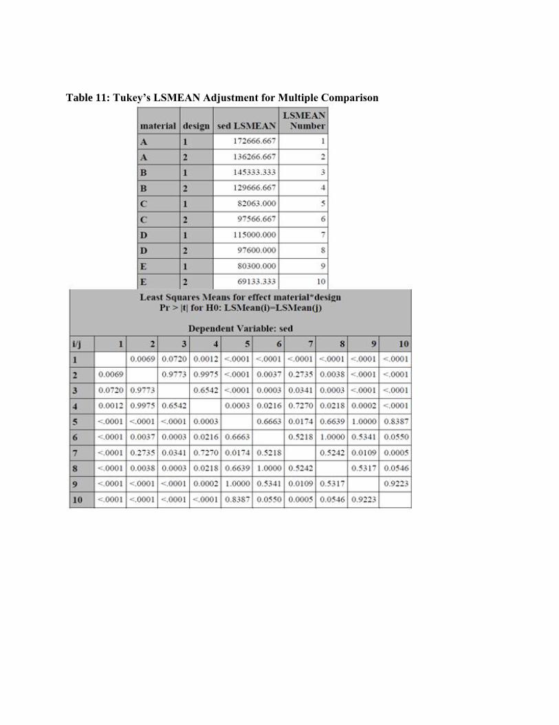
Table 11: Tukey’s LSMEAN Adjustment for Multiple Comparison
(a)
(b)
Figure 8: Interaction plots between the factors
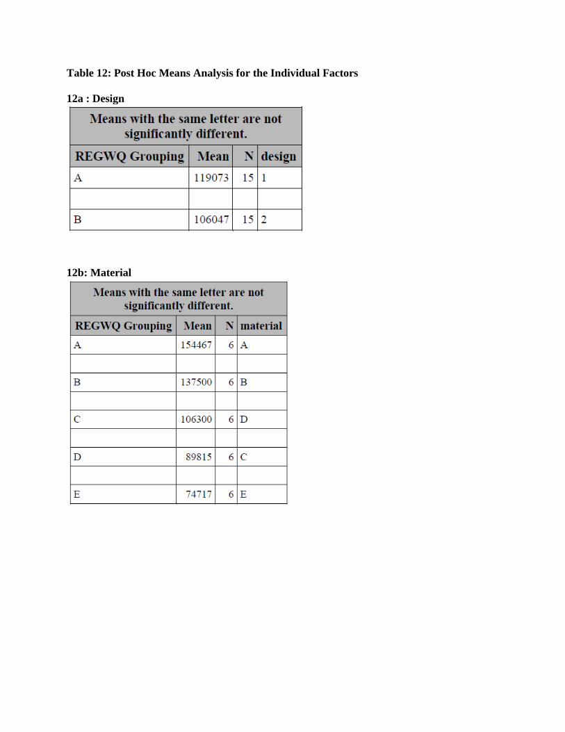
Table 12: Post Hoc Means Analysis for the Individual Factors
12a : Design
12b: Material

3.4 Failure Features
The failure features of the structures depend mostly on the design criterion used. Most of
those designed based on maximum stiffness criterion failed at the flange as shown in Fig. 9 for
any material combination. Their flange widths are generally smaller than those designed based
on maximum strength criterion. It shows that higher stresses are concentrated at the neck of the
flanges. Rather than fracture by tearing the materials, most of them deform and in some cases,
the consolidated foils delaminate as shown Fig. 10. However, none of the maximum strength
structures failed at the flange. MetPreg® reinforced maximum strength structures generally failed
at the left hand side tension members. The failures occurred on those members at the edge-to-
edge foil joints of the Al 3003 matrix materials or at the edge-to-edge joint of the reinforcing
MetPreg® materials. The right hand side tension members did not have any foil joint; as such no
fracture occurred on them. The left tension members were cut perpendicular to the direction of
consolidated foils, this make them to have intra-layer edge-to-edge joints. The right hand tension
members were however, cut along the direction of foil consolidation. The properties of the joints
have been characterized in earlier work (Obielodan et al., 2010A)
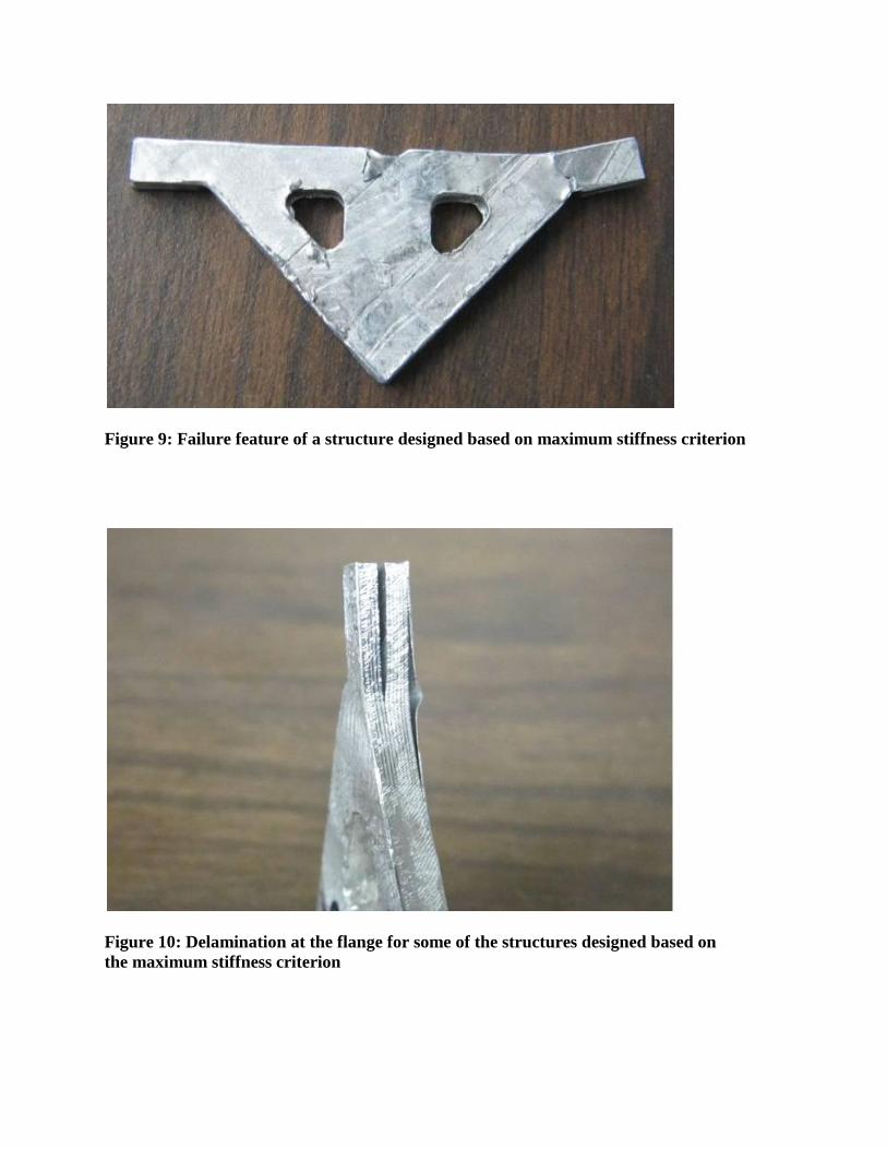
Figure 9: Failure feature of a structure designed based on maximum stiffness criterion
Figure 10: Delamination at the flange for some of the structures designed based on
the maximum stiffness criterion
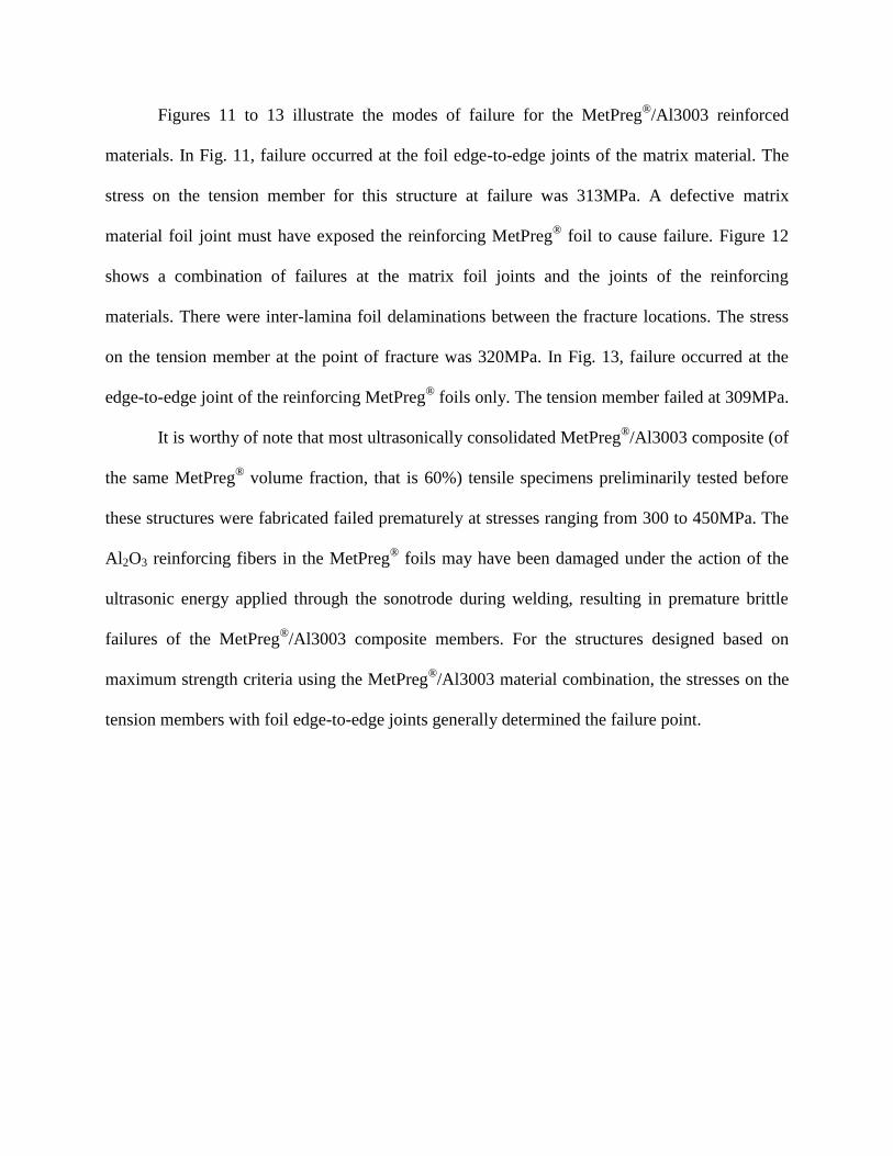
Figures 11 to 13 illustrate the modes of failure for the MetPreg®/Al3003 reinforced
materials. In Fig. 11, failure occurred at the foil edge-to-edge joints of the matrix material. The
stress on the tension member for this structure at failure was 313MPa. A defective matrix
material foil joint must have exposed the reinforcing MetPreg®
foil to cause failure. Figure 12
shows a combination of failures at the matrix foil joints and the joints of the reinforcing
materials. There were inter-lamina foil delaminations between the fracture locations. The stress
on the tension member at the point of fracture was 320MPa. In Fig. 13, failure occurred at the
edge-to-edge joint of the reinforcing MetPreg® foils only. The tension member failed at 309MPa.
It is worthy of note that most ultrasonically consolidated MetPreg®/Al3003 composite (of
the same MetPreg® volume fraction, that is 60%) tensile specimens preliminarily tested before
these structures were fabricated failed prematurely at stresses ranging from 300 to 450MPa. The
Al2O3 reinforcing fibers in the MetPreg® foils may have been damaged under the action of the
ultrasonic energy applied through the sonotrode during welding, resulting in premature brittle
failures of the MetPreg®
/Al3003 composite members. For the structures designed based on
maximum strength criteria using the MetPreg®/Al3003 material combination, the stresses on the
tension members with foil edge-to-edge joints generally determined the failure point.
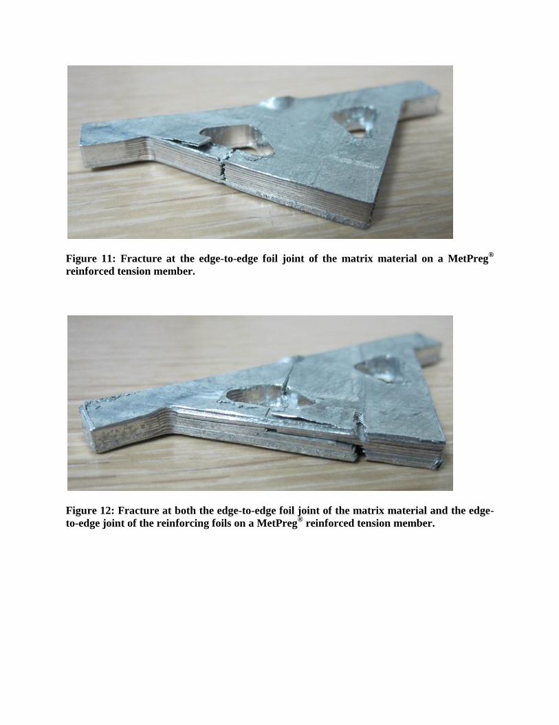
Figure 11: Fracture at the edge-to-edge foil joint of the matrix material on a MetPreg®
reinforced tension member.
Figure 12: Fracture at both the edge-to-edge foil joint of the matrix material and the edge-
to-edge joint of the reinforcing foils on a MetPreg® reinforced tension member.

Figure 13: Fracture at the edge-to-edge joint of the reinforcing foils on a MetPreg®
reinforced tension member.
Details of the failure stresses on the tension members of structures designed with
MetPreg®/Al3003 using maximum strength criterion and their single material copies are shown
in Fig. 14 (that is, those described with STR labels). Al-STR structures ultrasonically
consolidated exclusively with Al3003 foils and default foil overlap setting of width 23.90mm
fractured at the tension member at an average stress of 169MPa. This fracture stress is within the
range of tensile strengths obtained for tensile specimens fabricated with the same machine
parameters in earlier work (Obielodan et al., 2010A). Also, the W-Al-MSTR structures
fabricated exclusively with the wrought Al3003 substrate material failed at the tension member
at an average stress of 205MPa, which is within the range of the tensile strengths obtained for the
parent material.
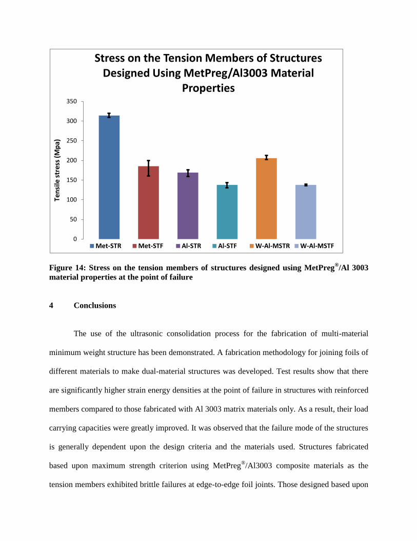
Figure 14: Stress on the tension members of structures designed using MetPreg®/Al 3003
material properties at the point of failure
4 Conclusions
The use of the ultrasonic consolidation process for the fabrication of multi-material
minimum weight structure has been demonstrated. A fabrication methodology for joining foils of
different materials to make dual-material structures was developed. Test results show that there
are significantly higher strain energy densities at the point of failure in structures with reinforced
members compared to those fabricated with Al 3003 matrix materials only. As a result, their load
carrying capacities were greatly improved. It was observed that the failure mode of the structures
is generally dependent upon the design criteria and the materials used. Structures fabricated
based upon maximum strength criterion using MetPreg®/Al3003 composite materials as the
tension members exhibited brittle failures at edge-to-edge foil joints. Those designed based upon
0
50
100
150
200
250
300
350
Ten
sile
str
ess
(Mp
a)Stress on the Tension Members of Structures
Designed Using MetPreg/Al3003 Material Properties
Met-STR Met-STF Al-STR Al-STF W-Al-MSTR W-Al-MSTF

maximum stiffness criterion generally failed at the flange of the triangular structure irrespective
of the material combination. From the results of this work, it is believed that multi-material
structures can be fabricated for real life applications using appropriate material combinations.
References
Arcaute K., Mann B, and Wicker R. 2009. Stereolithography of spatially controlled
multi-material bioactive poly(ethylene glycol) scaffolds, Acta biomaterialia, 6(3),
pp.1047-1054
Cohen D.L., Malone E., Lipson H. Bonassar L.J., 2006. “Direct Freeform Fabrication of
Seeded Hydrogels in Arbitrary Geometries”, Tissue Engineering, 12(5),
pp.1325-1335.
Dewhurst Peter, 2001. Analytical solutions and numerical procedures for minimum-
weight Michell structures, Journal of the Mechanics and Physics of Solids, 49(3) 445
– 467
Dewhurst Peter, 2005. A general optimality criterion for strength and stiffness of dual-
Material property structures, International journal of mechanical sciences, 47(2),
pp.293-302.
Domack M.S., and Baughman J.M., 2005. Development of nickel-titanium graded
composition components, Rapid prototyping journal, 11(1), pp.41-51.
Foroozmehr E., Sarrafi R., Hamid S. and Kovacevic R. Synthesizing of functionally
graded surface composites by laser powder deposition process for slurry erosion
applications. Proceedings of 20th
solid freeform fabrication symposium, Austin, TX,
USA, August 3-5, 2009.
Griffith M.L., Harwell L.D., Romero J.T., Schlienger E., Atwood C.L., Smugeresky J.E.,.
Multi-material processing by LENS, Proceedings of the 8th
solid freeform fabrication
symposium, Austin, TX, PP.387, 1997
Inamdar A., Magana M., Medina F., Grageda., Wicker R. “Development of automated
multiple material stereolithography machine”, Proceedings of the 17th
solid freeform
fabrication symposium, Austin, TX, USA, August 2006.
Jae-Won Choi J., MacDonald E., and Wicker R. Multiple material microstereolithography.
Proceedings of 20th
solid freeform fabrication symposium, Austin, TX, USA, August
3-5, 2009
Janaki Ram G.D. and Brent Stucker, 2008. LENS® deposition of CoCrMo coatings on
titanium implant structures, Journal of manufacturing science and engineering –
Transactions of the ASME, 130(2), pp. 024503-1 to 024503-5.
Janaki Ram G.D., Robinson C., Yang and Stucker B.E., 2007. Use of ultrasonic
Consolidation for multi-material structures”, Rapid prototyping journal, 13(4),
pp.226-235.
Kruger S., Wagner G. and Eifler D., 2004. Utrasonic welding of metal/composite joints,
Advanced engineering materials, 6(3), pp.157-159.
Liu W., and DuPont J.N., 2003. Fabrication of functionally graded TiC/Ti composites by
laser engineered net shaping, Scripta materialia, 48(8), pp.1337-1342
Malone E., Rasa K., Cohen D., Isaacson T., Lashley H., Lipson H., 2004. “Freeform
Fabrication of Zinc-Air Batteries and Electromechanical Assemblies”, Rapid
Prototyping Journal, 10(1), pp.58-69.
Michell, A.G.M., 1904, Limits of economy of material in frame-structures, Philosophical
magazine, 8(47), pp.589-597.
Obielodan J.O. and Stucker B.E. Effects of post processing heat treatments on the bond
quality and mechanical strength of Ti/Al3003 dual materials fabricated using
ultrasonic consolidation, Proceedings of the 20th
solid freeform fabrication
symposium, Austin, TX, USA, August 3-5, 2009.
Obielodan J.O., Janaki Ram G.D., Stucker B.E., Taggart D.G., 2010A. Minimizing
defects between adjacent foils in ultrasonically consolidated parts, Journal of
engineering materials and technology, 132(1), pp. 011006-1 - 011006-8
Obielodan J.O., Ceylan A., Murr L.E., Stucker B.E., 2010B. Multi-material bonding in
ultrasonic consolidation, Rapid prototyping journal, 16(3), pp.180-188
Selyugin S.V., 2004. Some general results for optimal structures, Structural and Multi-
disciplinary optimization, 26(5), pp.357-366.
White D.R., 2003. Ultrasonic consolidation of aluminum tooling, Advanced materials &
processes, 161(1), pp.64-65.
Wicker R. Medina F. and Elkins C. Multiple material micro-fabrication: extending
stereolithography to tissue engineering and other novel applications, Proceedings of
solid freeform fabrication symposium, Austin, TX, USA, August 2004.