dual fuel gas / light oil burners - power equipment...
TRANSCRIPT
Installation, use and maintenance instructions
Dual Fuel Gas / Light Oil Burners
RLS 70 - 100 - 130
Modulating Gas / Low - High Oil Operation
C6505059

2
CONTENTS
FUEL OIL / GAS
Technical data . . . . . . . . . . . . . . . . . . . . . . . . . . . . . . . . . . page 3Burner models . . . . . . . . . . . . . . . . . . . . . . . . . . . . . . . . . . . . . . . 3Accessories . . . . . . . . . . . . . . . . . . . . . . . . . . . . . . . . . . . . . . . . . 3Burner description . . . . . . . . . . . . . . . . . . . . . . . . . . . . . . . . . . . . 4Packaging - Weight. . . . . . . . . . . . . . . . . . . . . . . . . . . . . . . . . . . . 4Max. dimensions. . . . . . . . . . . . . . . . . . . . . . . . . . . . . . . . . . . . . . 4Standard equipment . . . . . . . . . . . . . . . . . . . . . . . . . . . . . . . . . . . 4Firing rates . . . . . . . . . . . . . . . . . . . . . . . . . . . . . . . . . . . . . . . . . . 5Minimum furnace dimensions. . . . . . . . . . . . . . . . . . . . . . . . . . . . 5Installation . . . . . . . . . . . . . . . . . . . . . . . . . . . . . . . . . . . . . . . . . . 6Boiler plate . . . . . . . . . . . . . . . . . . . . . . . . . . . . . . . . . . . . . . . . . . 6Blast tube length . . . . . . . . . . . . . . . . . . . . . . . . . . . . . . . . . . . . . 6Securing the burner to the boiler . . . . . . . . . . . . . . . . . . . . . . . . . 6
FUEL OIL
Nozzle selection . . . . . . . . . . . . . . . . . . . . . . . . . . . . . . . . . . . . . . 6Nozzle assembly . . . . . . . . . . . . . . . . . . . . . . . . . . . . . . . . . . . . . 7Adjustments before firing . . . . . . . . . . . . . . . . . . . . . . . . . . . . . . . 7
FUEL OIL
Pump . . . . . . . . . . . . . . . . . . . . . . . . . . . . . . . . . . . . . . . . . . . . . . 8Fuel supply . . . . . . . . . . . . . . . . . . . . . . . . . . . . . . . . . . . . . . . . . . 9Hydraulic connections . . . . . . . . . . . . . . . . . . . . . . . . . . . . . . . . . 9Pump priming . . . . . . . . . . . . . . . . . . . . . . . . . . . . . . . . . . . . . . . . 9
GAS
Gas pressure . . . . . . . . . . . . . . . . . . . . . . . . . . . . . . . . . . . . . . . 10Gas line . . . . . . . . . . . . . . . . . . . . . . . . . . . . . . . . . . . . . . . . . . . 11Adjustment before firing . . . . . . . . . . . . . . . . . . . . . . . . . . . . . . . 12
FUEL OIL / GAS
Servomotor. . . . . . . . . . . . . . . . . . . . . . . . . . . . . . . . . . . . . . . . . 13Burner starting . . . . . . . . . . . . . . . . . . . . . . . . . . . . . . . . . . . . . . 14
FUEL OIL
Fuel oil adjustment . . . . . . . . . . . . . . . . . . . . . . . . . . . . . . . . . . . 14
GAS
Gas adjustment . . . . . . . . . . . . . . . . . . . . . . . . . . . . . . . . . . . . . 14
FUEL OIL / GAS
Maintenance. . . . . . . . . . . . . . . . . . . . . . . . . . . . . . . . . . . . . . . . 17Oil hydraulic system layout . . . . . . . . . . . . . . . . . . . . . . . . . . . . . 18Oil pressure switch . . . . . . . . . . . . . . . . . . . . . . . . . . . . . . . . . . . 18
ELECTRICAL WIRING
Field wiring diagram - Burner mounted LFL. . . . . . . . . . . . . . . . 19Factory wiring diagram - remote panel. . . . . . . . . . . . . . . . . . . . 20Appendix - Burner firing rates according to air density. . . . . . . . 21Flame signal measurement . . . . . . . . . . . . . . . . . . . . . . . . . . . . 22Siemens LFL control sequence of operation . . . . . . . . . . . . . . . 22Siemens LFL control troubleshooting guide . . . . . . . . . . . . . . . . 23Start up report . . . . . . . . . . . . . . . . . . . . . . . . . . . . . . . . . . . . . . 24
Factory wiring diagram - burner mounted LFL ( see attached insert)
WARNING
If you smell gas:
• Do not touch any electrical items.• Open all windows.• Close all gas supply valves.• Contact your local gas authority immediately.
Do not store flammable or hazardous materials in the vicinity of fuel burning appliances.
Improper installation, adjustment, alteration, service or main-tenance can cause property damage, personal injury or death. Refer to this manual for instructional or additional in-formation. Consult a certified installer, service representative or the gas supplier for further assistance.
Burner shall be installed in accordance with manufacturers requirements as outlined in this manual, local codes and au-thorities having juristiction.

3
TECHNICAL DATA
(1)
Reference conditions: Ambient temperature 68 °F (20°C) - Barometric pressure 394” WC - Altitude 329 ft.
(2)
Pressure at test point 18)(A)p.4 with zero pressure in the combustion chamber and maximum burner output.
(3)
Sound pressure measured in manufacturer’s combustion laboratory, with burner operating on test boiler and at maximum rated output.
(4)
Equivalent Btu values based on 1 USGPH = 140,000 Btu/hr.
Burner model designations:
ACCESSORIES
(optional):
• KIT FOR LENGTHENING THE COMBUSTION HEAD
L =Standard lengthL1 =Length obtainable with the kitCode
3010267
L = 9
27/32
” L1 = 15
5/32
” • RLS 70Code
3010268
L = 9
27/32
” L1 = 15
5/32
” • RLS 100Code
3010269
L = 9
27/32
” L1 = 15
5/32
” • RLS 130
• KIT FOR LPG OPERATION -
Code
3010305:
The kit allows the RLS 70-100-130 burners to operate on LPG
.
•
GAS TRAIN ACCORDING TO UL STANDARDS:
see page 11.
Model RLS 70 RLS 100 RLS 130
Output
(1)
Delivery
(1)
Maximum MBtu/hr
(4)
1750 - 3094 2646 - 4396 3500 - 5292kW 513 - 907
12.5 - 22.1775 - 128818.9 - 31.4
1026 - 155125 - 37.8GPH
Minimum MBtu/hr
(4)
854 1330 1750kW 250
6.13909.5
51312.5GPH
Fuel #2 Fuel oil Natural gas / Propane gas
Gas pressure at maximum delivery
(2)
Gas: Natural gas
“ WC 2.44 3.94 4.29
Operation Low-high light oil Low-high-low / modulating gas
Nozzles number 2Standard applications Boilers: water, steam, thermal oilAmbient temperature °F 32 - 104 (0 - 40 °C)Combustion air temperature °F max 140 (60 °C)Main power supply (+/- 10%) V/Ph/Hz 208 - 230 / 460 / 575 /3/60Electric motors rpm 3400Fan motor V
W - HPA
208 - 230 / 460 / 5751100 - 1.5
4.8 - 2.8 - 2.3
208 - 230 / 460 / 5751800 - 2.5
6.7 - 3.9 - 3.2
208 - 230 / 460 / 5752200 - 3
8.8 - 5.1 - 4.1Pump motor V
W - HPA
208 - 230 / 460 / 575550 - 0.75
2.6 - 1.5 - 1.2Ignition transformer Oil V1 - V2
I1 - I2120 V - 2 x 5 kV3.7 A - 35 mA
Gas V1 - V2I1 - I2
120 V - 1 x 7 kV1.6 A - 23 mA
Pump delivery (at 174 PSI)pressure rangefuel temperature
GPHPSI
° F max
52.5145 - 290
140 (60 °C)Electrical power consumption W max 2200 3000 3400Electrical protection NEMA 1Noise levels
(3)
dBA 74 77.5 80
Model Code Voltage Flame safeguard
RLS 70
C9534000
(3485070)
C9534001
(3485070)
C9634000
(3485072)
C9634001
(3485072)
208-230/460/3/60575/3/60
208-230/460/3/60575/3/60
Burner mountedBurner mountedRemote panelRemote panel
RLS 100
C9535000
(3485270)
C9535001
(3485270)
C9635000
(3485272)
C9635001
(3485272)
208-230/460/3/60575/3/60
208-230/460/3/60575/3/60
Burner mountedBurner mountedRemote panelRemote panel
RLS 130
C9536000
(3485470)
C9536001
(3485470)
C9636000
(3485472)
C9636001
(3485472)
208-230/460/3/60575/3/60
208-230/460/3/60575/3/60
Burner mountedBurner mountedRemote panelRemote panel
Important:
tThe installer is responsible for the supply and installation of any required safety device(s) not indicated in this manual.

4
BURNER DESCRIPTION (A)
1 Combustion head2 Ignition electrodes3 Screw for combustion head adjustment4 Sleeve5 Relay for oil / gas selection6 Fan motor7 Motors contactors and thermal cut-out with reset but-
ton8 UV scanner9 Terminal strip10 Knockouts for electrical connections by installer11 Oil / gas selector switch12 Flame safeguard13 Flame inspection window14 Low air pressure switch
(differential operating type)15 Slide bars for opening the burner and inspecting the
combustion head16 Safety solenoid valve17 Low and high fire oil valves18 Gas pressure test point and head fixing screw19 Air pressure test point20 Servomotor.
When the burner is not operating the air damper isfully closed in order to reduce heat loss.
21 Pump motor22 Low oil pressure switch23 Pilot attachment24 Pump25 Gas input connection26 Boiler mounting flange27 Flame stability disk28 Screw securing fan to sleeve
Two types of burner failure may occur:Flame relay lock-out: if the flame relay 12)(A) pushbut-ton lights up, it indicates that the burner is in lock-out.To reset, press the pushbutton.Motor trip: release by pressing the pushbutton on thethermal overload 7)(A).
PACKAGING - WEIGHT (B)
- Approximate measure-ments• The burners are skid mounted. Outer dimensions ofpackaging are indicated in (B).• The weight of the burner complete with packaging isindicated in Table (B).
MAX. DIMENSIONS (C)
-
Approximate measure-mentsThe maximum dimensions of the burners are given in(C).Inspection of the combustion head requires the burnerto be opened and the rear part withdrawn on the slidebars.The maximum dimension of the burner when open, with-out casing, is give in measurement I.
STANDARD EQUIPMENT
1 - Gas train flange1 - Flange gasket4 - Flange fixing screws1 - Burner head gasket4 - Screws to secure the burner flange to the boiler:
1/2
W x 1
3/8
”1 - Adaptor G
1/8
“ /
1/8
“ NPT2 - Flexible hoses1 - Instruction booklet1 - Spare parts list
(A)
inch A B C lbs
RLS 70 4627/32“ 291/8“ 271/4“ 159
RLS 100 4627/32“ 291/8“ 271/4“ 165
RLS 130 4627/32“ 291/8“ 271/4“ 170
(B)
RLS A B C D E F G H I L M N O
70 271/2“ 113/8“ 161/8“ 2127/32“ 333/32“ 927/32“ 71/16“ 1615/16“ 4523/32“ 87/16“ 59/32” 823/32“ 2“
100 287/8“ 1225/32“ 161/8“ 2127/32“ 333/32“ 927/32“ 71/16“ 1615/16“ 4523/32“ 87/16“ 59/32” 823/32“ 2“
130 287/8“ 1225/32“ 161/8“ 2127/32“ 333/32“ 927/32“ 77/16“ 1615/16“ 4523/32“ 87/16“ 59/32” 823/32“ 2“
(C)
D2299
D36
D2300
5
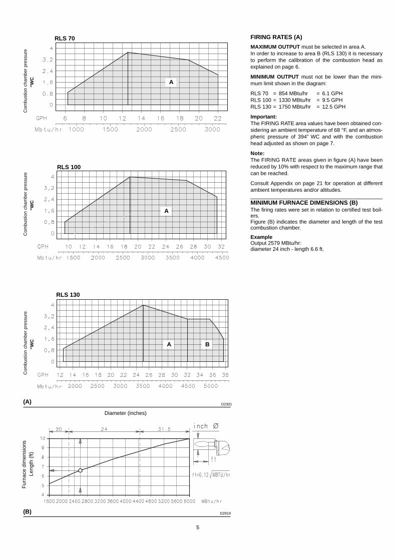
FIRING RATES (A)
MAXIMUM OUTPUT must be selected in area A.In order to increase to area B (RLS 130) it is necessaryto perform the calibration of the combustion head asexplained on page 6.
MINIMUM OUTPUT must not be lower than the mini-mum limit shown in the diagram:
RLS 70 = 854 MBtu/hr = 6.1 GPHRLS 100 = 1330 MBtu/hr = 9.5 GPHRLS 130 = 1750 MBtu/hr = 12.5 GPH
Important: The FIRING RATE area values have been obtained con-sidering an ambient temperature of 68 °F, and an atmos-pheric pressure of 394” WC and with the combustionhead adjusted as shown on page 7.
Note: The FIRING RATE areas given in figure (A) have beenreduced by 10% with respect to the maximum range thatcan be reached.
Consult Appendix on page 21 for operation at differentambient temperatures and/or altitudes.
MINIMUM FURNACE DIMENSIONS (B)The firing rates were set in relation to certified test boil-ers. Figure (B) indicates the diameter and length of the testcombustion chamber.
ExampleOutput 2579 MBtu/hr:diameter 24 inch - length 6.6 ft.
(A)
RLS 70
RLS 100
RLS 130
Com
bust
ion
cham
ber
pres
sure
“WC
C
ombu
stio
n ch
ambe
r pr
essu
re“W
C
Com
bust
ion
cham
ber
pres
sure
“WC
A B
D2301
(B) D2919
A
A
ft
Diameter (inches)
Leng
th (
ft)F
urna
ce d
imen
sion
s
6
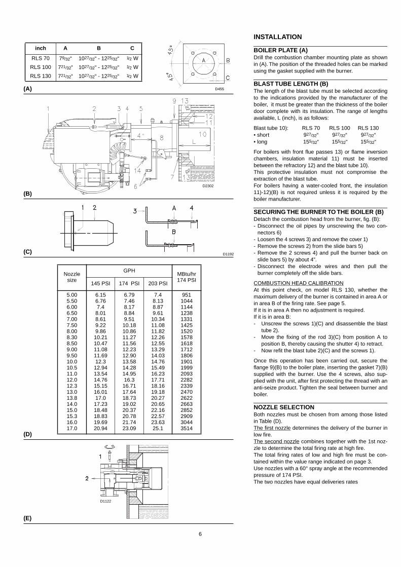
INSTALLATION
BOILER PLATE (A)Drill the combustion chamber mounting plate as shownin (A). The position of the threaded holes can be markedusing the gasket supplied with the burner.
BLAST TUBE LENGTH (B)The length of the blast tube must be selected accordingto the indications provided by the manufacturer of theboiler, it must be greater than the thickness of the boilerdoor complete with its insulation. The range of lengthsavailable, L (inch), is as follows:
Blast tube 10): RLS 70 RLS 100 RLS 130• short 927/32“ 927/32“ 927/32“• long 155/32“ 155/32“ 155/32“
For boilers with front flue passes 13) or flame inversionchambers, insulation material 11) must be insertedbetween the refractory 12) and the blast tube 10).This protective insulation must not compromise theextraction of the blast tube.For boilers having a water-cooled front, the insulation11)-12)(B) is not required unless it is required by theboiler manufacturer.
SECURING THE BURNER TO THE BOILER (B)Detach the combustion head from the burner, fig. (B):- Disconnect the oil pipes by unscrewing the two con-
nectors 6)- Loosen the 4 screws 3) and remove the cover 1)- Remove the screws 2) from the slide bars 5)- Remove the 2 screws 4) and pull the burner back on
slide bars 5) by about 4”.- Disconnect the electrode wires and then pull the
burner completely off the slide bars.
COMBUSTION HEAD CALIBRATIONAt this point check, on model RLS 130, whether themaximum delivery of the burner is contained in area A orin area B of the firing rate. See page 5.If it is in area A then no adjustment is required.If it is in area B:- Unscrew the screws 1)(C) and disassemble the blast
tube 2).- Move the fixing of the rod 3)(C) from position A to
position B, thereby causing the shutter 4) to retract.- Now refit the blast tube 2)(C) and the screws 1).
Once this operation has been carried out, secure theflange 9)(B) to the boiler plate, inserting the gasket 7)(B)supplied with the burner. Use the 4 screws, also sup-plied with the unit, after first protecting the thread with ananti-seize product. Tighten the seal between burner andboiler.
NOZZLE SELECTIONBoth nozzles must be chosen from among those listedin Table (D).The first nozzle determines the delivery of the burner inlow fire.The second nozzle combines together with the 1st noz-zle to determine the total firing rate at high fire.The total firing rates of low and high fire must be con-tained within the value range indicated on page 3.Use nozzles with a 60° spray angle at the recommendedpressure of 174 PSI.The two nozzles have equal deliveries rates
(D)
inch A B C
RLS 70 79/32“ 1027/32“ - 1225/32“ 1/2 W
RLS 100 721/32“ 1027/32“ - 1225/32“ 1/2 W
RLS 130 721/32“ 1027/32“ - 1225/32“ 1/2 W
D455(A)
(B)
(E)
D2302
Nozzlesize
GPHMBtu/hr174 PSI
145 PSI 174 PSI 203 PSI
5.005.506.006.507.007.508.008.308.509.009.5010.010.511.012.012.313.013.814.015.015.316.017.0
6.156.767.4
8.018.619.229.86
10.2110.4711.0811.6912.3
12.9413.5414.7615.1516.0117.0
17.2318.4818.8319.6920.94
6.797.468.178.849.51
10.1810.8611.2711.5612.2312.9013.5814.2814.9516.3
16.7117.6418.7319.0220.3720.7821.7423.09
7.48.138.879.61
10.3411.0811.8212.2612.5513.2914.0314.7615.4916.2317.7118.1619.1820.2720.6522.1622.5723.6325.1
9511044114412381331142515201578161817121806190119992093228223392470262226632852290930443514
D1122
(C) D1192
7
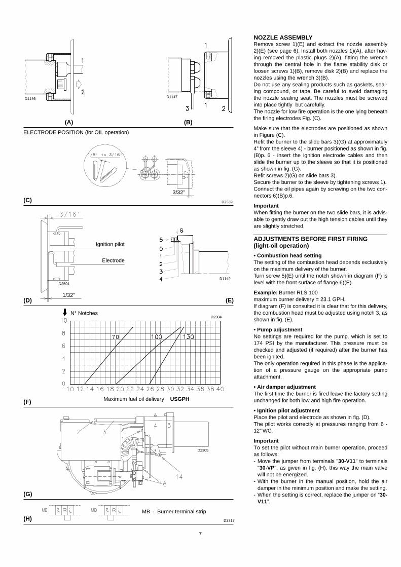
NOZZLE ASSEMBLYRemove screw 1)(E) and extract the nozzle assembly2)(E) (see page 6). Install both nozzles 1)(A), after hav-ing removed the plastic plugs 2)(A), fitting the wrenchthrough the central hole in the flame stability disk orloosen screws 1)(B), remove disk 2)(B) and replace thenozzles using the wrench 3)(B).Do not use any sealing products such as gaskets, seal-ing compound, or tape. Be careful to avoid damagingthe nozzle sealing seat. The nozzles must be screwedinto place tightly but carefully.The nozzle for low fire operation is the one lying beneaththe firing electrodes Fig. (C).
Make sure that the electrodes are positioned as shownin Figure (C).Refit the burner to the slide bars 3)(G) at approximately4” from the sleeve 4) - burner positioned as shown in fig.(B)p. 6 - insert the ignition electrode cables and thenslide the burner up to the sleeve so that it is positionedas shown in fig. (G).Refit screws 2)(G) on slide bars 3).Secure the burner to the sleeve by tightening screws 1).Connect the oil pipes again by screwing on the two con-nectors 6)(B)p.6.
ImportantWhen fitting the burner on the two slide bars, it is advis-able to gently draw out the high tension cables until theyare slightly stretched.
ADJUSTMENTS BEFORE FIRST FIRING(light-oil operation)
• Combustion head settingThe setting of the combustion head depends exclusivelyon the maximum delivery of the burner.Turn screw 5)(E) until the notch shown in diagram (F) islevel with the front surface of flange 6)(E).
Example: Burner RLS 100maximum burner delivery = 23.1 GPH.If diagram (F) is consulted it is clear that for this delivery,the combustion head must be adjusted using notch 3, asshown in fig. (E).
• Pump adjustmentNo settings are required for the pump, which is set to174 PSI by the manufacturer. This pressure must bechecked and adjusted (if required) after the burner hasbeen ignited.The only operation required in this phase is the applica-tion of a pressure gauge on the appropriate pumpattachment.
• Air damper adjustmentThe first time the burner is fired leave the factory settingunchanged for both low and high fire operation.
• Ignition pilot adjustmentPlace the pilot and electrode as shown in fig. (D). The pilot works correctly at pressures ranging from 6 -12” WC.
ImportantTo set the pilot without main burner operation, proceedas follows:- Move the jumper from terminals "30-V11" to terminals
"30-VP", as given in fig. (H), this way the main valvewill not be energized.
- With the burner in the manual position, hold the airdamper in the minimum position and make the setting.
- When the setting is correct, replace the jumper on “30-V11”.
(A)
(D)
(H)
D1146 D1147
D2539
D1149
N° Notches
Maximum fuel oil delivery USGPH
D2304
(B)
D2305
ELECTRODE POSITION (for OIL operation)
(G)
(F)
MB - Burner terminal strip
(C)
(E)
D2317
Ignition pilot
Electrode
D2591
3/32”
1/32”

8
PUMP (A)1 - Suction 1/4” NPT2 - Return 1/4” NPT3 - Pressure gauge attachment G 1/8”4 - Vacuum gauge attachment G 1/8”5 - Pressure regulator
A - Min. delivery rate at 174 PSI pressureB - Delivery pressure rangeC - Max. suction D - Viscosity rangeE - Max fuel oil temperatureF - Max. suction and return pressureG - Pressure calibration in the factoryH - Filter mesh width
(A)
PUMPSUNTEC AJ6 CC
AJ6 CC
ABCDEFGH
GPHPSIPSIcSt
°F - °CPSIPSIinch
52.5145 - 290
6.52.8 - 75140 - 60
29174
0.006
D2306

9
FUEL SUPPLY (A)The burner is equipped with a self-priming pump whichis capable of feeding itself within the limits listed in thetable at the left.The tank higher than the burner AThe distance "P" must not exceed 33 ft in order to avoidsubjecting the pump's seal to excessive strain; the dis-tance "V" must not exceed 13 ft in order to permit pumpself-priming even when the tank is almost completelyempty.The tank lower than the burner BPump suction pressures higher than 6.5 PSI must notbe exceeded because at higher levels gas is releasedfrom the fuel, the pump starts making noise and itsworking life-span decreases.It is good practice to ensure that the return and suctionlines enter the burner from the same height; in this way itwill be more improbable that the suction line fails toprime or stops priming.
KeyH =Pump/Foot valve height differenceL =Piping lengthØ =Inside pipe diameter1 =Burner2 =Pump3 =Filter4 =Manual on/off valve5 =Suction line6 =Foot valve7 =Return line
HYDRAULIC CONNECTIONS (B)The pumps are equipped with a by-pass that separatesreturn line and suction line. The pumps are installed onthe burner with the by-pass closed by screw 6), see dia-gram page 18.It is therefore necessary to connect both hoses to thepump.Damage to the pump seal will occur immediately if itis run with the return line closed and the by-passscrew inserted.Remove the plugs from the suction and return connec-tions of the pump.Insert the hose connections with the supplied seals intothe connections and screw them down. Take care that the hoses are not stretched or twistedduring installation.Install the hoses where they cannot be stepped on orcome into contact with hot surfaces of the boiler andwhere they do not hamper the opening of the burner.Now connect the other end of the hoses to the suctionand return lines.
PUMP PRIMING- Before starting the burner, make sure that the
tank return line is not clogged. Obstructions inthe line could cause damage to the pump seal.(The pump leaves the factory with the by-passclosed).
- Also check to make sure that the valves located onthe suction line are open and that there is sufficientfuel in the tank.
- For self-priming to take place, one of the screws 3) ofthe pump (See fig.(A) page 8) must be loosened inorder to bleed off the air contained in the suction line.
(A)
6
7
5 3
2
1
4
- H
315 /
16 + H
V
P
57
A
B
6
D1178
+ H- Hft
L ft
RLS 70 - 100 - 130Ø inch
1/2” 9/16” 5/8”
+ 13+ 10+ 6.6+ 3.3+ 1.6
234204174145132
454401349296270
493493493493493
0 118 243 451
- 1.6- 3.3- 6.6- 10- 13
105926333-
2171911388633
40535926617482
D2308(B)

10
GAS PRESSUREThe adjacent tables show minimum pressure lossesalong the gas supply line depending on the maximumburner output.
Column 1Pressure loss at combustion head.Gas pressure measured at test point 1)(B), with:• Combustion chamber at 0” WC• Burner operating at maximum output• Natural gas
Column 2Pressure loss at butterfly valve.
Calculate the approximate high fire output of the burneras follows:- subtract the combustion chamber pressure from the
gas pressure measured at test point 1)(B).- Find the nearest pressure value to your result in col-
umn 1 of the table for the burner in question.- Read off the corresponding output on the left.
Example - RLS 100• Maximum output operation• Natural gas• Gas pressure at test point 1)(B) = 4.41” WC• Pressure in combustion chamber = 0.79” WC
4.41 - 0.79 = 3.62” WCA maximum output of 3616 MBtu/hr shown in Table RLS100 corresponds to 3.62” WC pressure, column 1, natu-ral gas.This value serves as a rough guide, the effective deliv-ery must be measured at the gas meter.
To calculate the required gas pressure at test point1)(B), set the maximum output required from the burner:- find the nearest output value in the table for the burner
in question.- Read off the pressure at test point 1)(B) on the right in
column 1.- Add this value to the estimated pressure in the com-
bustion chamber.
Example - RLS 100• Maximum required burner output: 3616 MBtu/hr• Natural gas • Gas pressure at burner output of 3616 MBtu/hr, taken
from table RLS 100, column 1, natural gas = 3.62” WC• Pressure in combustion chamber = 0.79” WC
3.62 + 0.79 = 4.41” WCpressure required at test point 1)(B).
(A)
(B)
RLS 70 ∆p (“ WC)
RLS 100 ∆p (“ WC)
RLS 130 ∆p (“ WC)
MBtu/hr 1 2
1750 2.17 0.08
1950 2.20 0.08
2140 2.24 0.12
2329 2.28 0.12
2519 2.32 0.12
2708 2.36 0.16
2897 2.40 0.16
3094 2.44 0.16
MBtu/hr 1 2
2646 3.15 0.16
2878 3.27 0.16
3125 3.39 0.20
3371 3.50 0.20
3616 3.62 0.24
3863 3.70 0.28
4109 3.82 0.31
4396 3.94 0.31
MBtu/hr 1 2
3500 3.66 0.39
3825 3.74 0.43
4128 3.82 0.51
4431 3.90 0.59
4734 4.09 0.67
5037 4.29 0.71
D2309
1
2
11
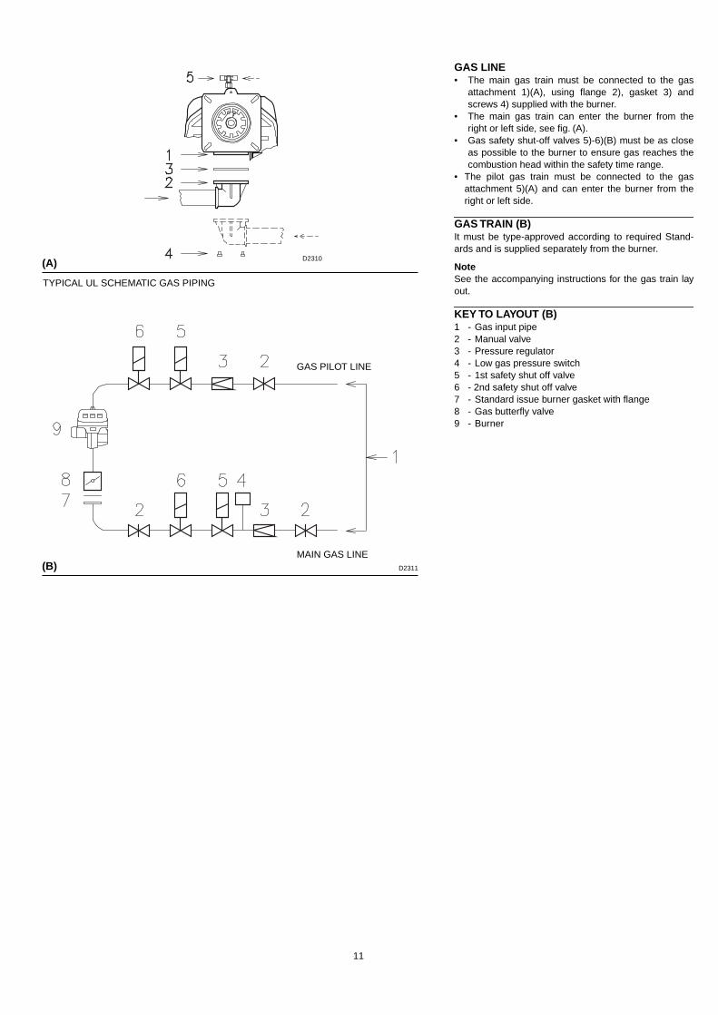
GAS LINE• The main gas train must be connected to the gas
attachment 1)(A), using flange 2), gasket 3) andscrews 4) supplied with the burner.
• The main gas train can enter the burner from theright or left side, see fig. (A).
• Gas safety shut-off valves 5)-6)(B) must be as closeas possible to the burner to ensure gas reaches thecombustion head within the safety time range.
• The pilot gas train must be connected to the gasattachment 5)(A) and can enter the burner from theright or left side.
GAS TRAIN (B)It must be type-approved according to required Stand-ards and is supplied separately from the burner.
NoteSee the accompanying instructions for the gas train layout.
KEY TO LAYOUT (B)1 - Gas input pipe2 - Manual valve3 - Pressure regulator4 - Low gas pressure switch5 - 1st safety shut off valve6 - 2nd safety shut off valve 7 - Standard issue burner gasket with flange8 - Gas butterfly valve9 - Burner
(A)
(B)
D2310
D2311
TYPICAL UL SCHEMATIC GAS PIPING
GAS PILOT LINE
MAIN GAS LINE

12
ADJUSTMENTS BEFORE FIRST FIRINGAdjustment of the combustion head has been illustratedon page 7. In addition, the following adjustments must also bemade: - Open manual valves up-stream from the gas train.- Adjust the low gas pressure switch to the start of the
scale (A).- Adjust the high gas pressure switch to the upper limit
of the scale (B).- Adjust the air pressure switch to the zero position of
the scale (C).- Purge the air from the gas line.- Fit a U-type manometer (D) to the gas pressure test
point on the sleeve.The manometer readings are used to calculate MAX.burner power using the tables on page 10.
Before starting up the burner it is good practice to adjustthe gas train so that ignition takes place in conditions ofmaximum safety, i.e. with gas delivery at the minimum.
(A)
(D)
LOW GAS PRESSURE SWITCH AIR PRESSURE SWITCHHIGH GAS PRESSURE SWITCH
(B) (C)
D2312

13
SERVOMOTORThe servomotor gives simultaneous regulation of the airdamper through the variable cam profile 4)(F) and thegas butterfly valve.It rotates by 130° in approx. 35 s.The factory settings must not be changed for the first fir-ing, just check that they comply with the details below.To open the servomotor, remove the screws and pull thecover outward, fig. (A).
CAMS AND TRIM POTENTIOMETERS FUNC-TIONS
Cam 1: 130° (GAS only)Limits rotation towards maximum for gas.
Cam 2: 0° (GAS and OIL)Limits rotation towards minimum, air damper closed onstand by.
Cam 3: 20° (GAS only)Limits gas ignition regulation.
Cam 4: 120° (OIL only)Limits rotation towards maximum, high fire.
Cam 5: 30° (OIL only)Regulates ignition position and low fire.
Cam 6: 110° (OIL only)Regulates the valve control position high fire.It must always be ahead of cam 5.
Cams 7 - 8: not used
Trim potentiometer MAX (gas only)Limits maximum modulation.It must be set near the stroke end (cam 1) to exploit asfar as possible the variable profile cam and maximumopening of the gas butterfly valve.
Trim potentiometer MIN (gas only)Limits minimum modulation.It must be set near the stroke end (cam 2) to exploit asfar as possible the variable profile cam.
Trim potentiometer POSLimits an intermediate operating position between MAXand MIN, supplying power to the "P" terminal in the ser-vomotor (through an external command). This functioncuts out any external signals.NoteUsing the slide switch to select MAX or MIN, the servo-motor goes into the position for the respective settings ofthe MAX and MIN TRIM POTENTIOMETERS.
When the settings are complete, place the slide switchon OPE (operate).
(D)
(F)
(E)
(C)
1 Servomotor2 Graduated sector for gas
butterfly valve3 Index for graduated sector 24 Adjustable profile cam5 Adjustment screws for cam
starting profile6 Adjustment fixing screws7 Adjustment screws for cam
and profile
Slide switch
Trim potentiometersPosition jumpers
D2277
D2585
D2594
D2593
(A)
(B)
NO
Figure above shows how the servo-motor is released to manually checkthere is no binding though its motion.
Don’t release the button indi-cated in this figure: the syn-cronization of the camsmade in factory would bechanged.
YES
14
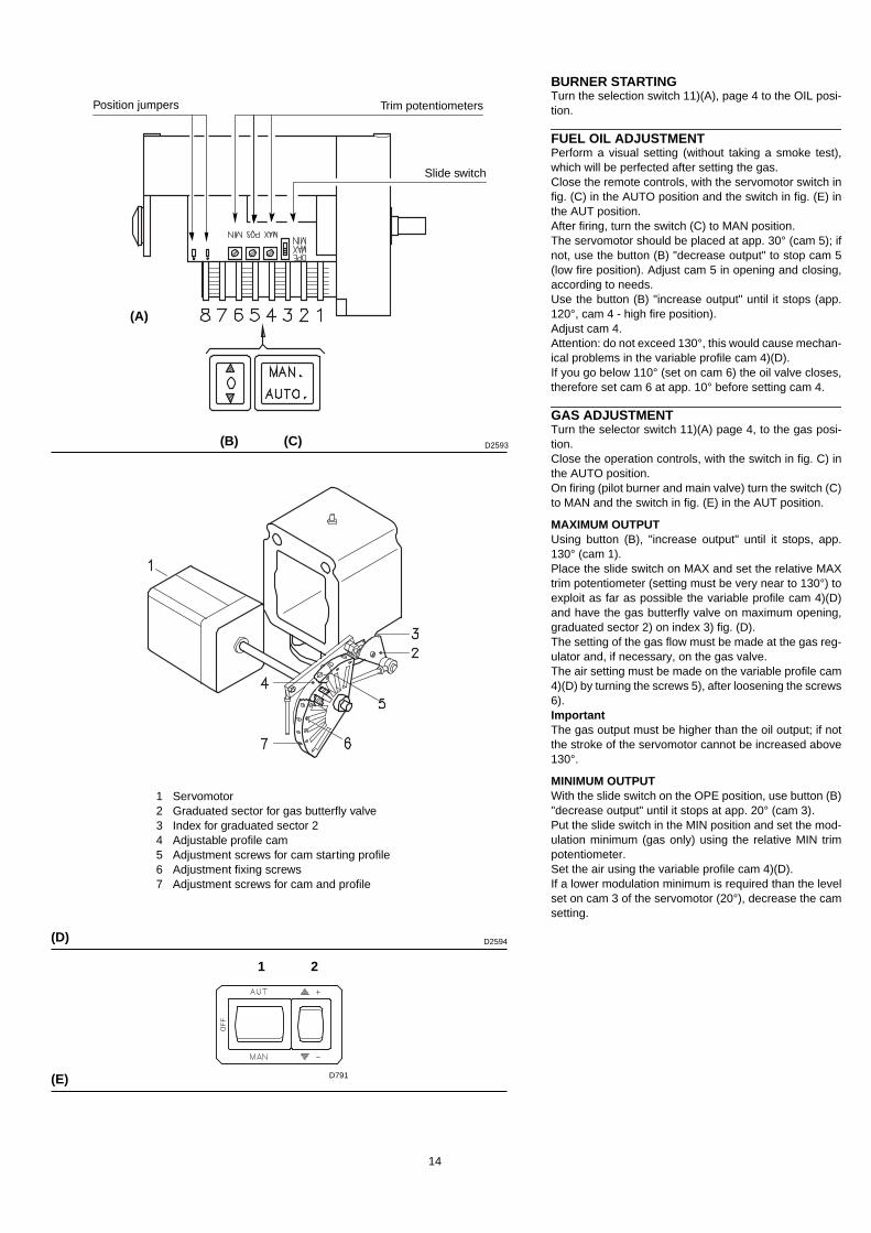
BURNER STARTINGTurn the selection switch 11)(A), page 4 to the OIL posi-tion.
FUEL OIL ADJUSTMENTPerform a visual setting (without taking a smoke test),which will be perfected after setting the gas.Close the remote controls, with the servomotor switch infig. (C) in the AUTO position and the switch in fig. (E) inthe AUT position.After firing, turn the switch (C) to MAN position.The servomotor should be placed at app. 30° (cam 5); ifnot, use the button (B) "decrease output" to stop cam 5(low fire position). Adjust cam 5 in opening and closing,according to needs.Use the button (B) "increase output" until it stops (app.120°, cam 4 - high fire position). Adjust cam 4.Attention: do not exceed 130°, this would cause mechan-ical problems in the variable profile cam 4)(D).If you go below 110° (set on cam 6) the oil valve closes,therefore set cam 6 at app. 10° before setting cam 4.
GAS ADJUSTMENTTurn the selector switch 11)(A) page 4, to the gas posi-tion.Close the operation controls, with the switch in fig. C) inthe AUTO position.On firing (pilot burner and main valve) turn the switch (C)to MAN and the switch in fig. (E) in the AUT position.
MAXIMUM OUTPUTUsing button (B), "increase output" until it stops, app.130° (cam 1).Place the slide switch on MAX and set the relative MAXtrim potentiometer (setting must be very near to 130°) toexploit as far as possible the variable profile cam 4)(D)and have the gas butterfly valve on maximum opening,graduated sector 2) on index 3) fig. (D).The setting of the gas flow must be made at the gas reg-ulator and, if necessary, on the gas valve. The air setting must be made on the variable profile cam4)(D) by turning the screws 5), after loosening the screws6).ImportantThe gas output must be higher than the oil output; if notthe stroke of the servomotor cannot be increased above130°.
MINIMUM OUTPUTWith the slide switch on the OPE position, use button (B)"decrease output" until it stops at app. 20° (cam 3).Put the slide switch in the MIN position and set the mod-ulation minimum (gas only) using the relative MIN trimpotentiometer.Set the air using the variable profile cam 4)(D).If a lower modulation minimum is required than the levelset on cam 3 of the servomotor (20°), decrease the camsetting.
(B) (C)
(D)
1 Servomotor2 Graduated sector for gas butterfly valve3 Index for graduated sector 24 Adjustable profile cam5 Adjustment screws for cam starting profile6 Adjustment fixing screws7 Adjustment screws for cam and profile
(A)
Slide switch
Trim potentiometersPosition jumpers
(E) D791
1 2
D2593
D2594
15
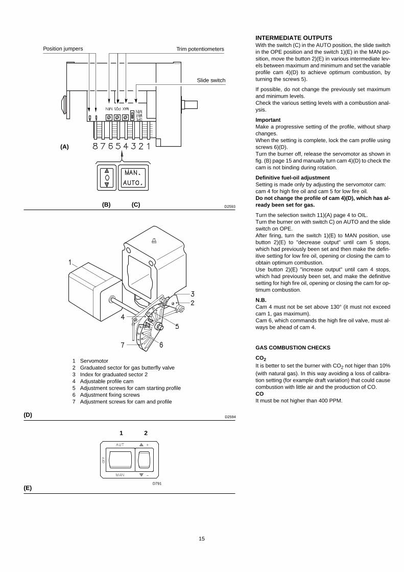
INTERMEDIATE OUTPUTSWith the switch (C) in the AUTO position, the slide switchin the OPE position and the switch 1)(E) in the MAN po-sition, move the button 2)(E) in various intermediate lev-els between maximum and minimum and set the variableprofile cam 4)(D) to achieve optimum combustion, byturning the screws 5).
If possible, do not change the previously set maximumand minimum levels.Check the various setting levels with a combustion anal-ysis.
ImportantMake a progressive setting of the profile, without sharpchanges.When the setting is complete, lock the cam profile usingscrews 6)(D).Turn the burner off, release the servomotor as shown infig. (B) page 15 and manually turn cam 4)(D) to check thecam is not binding during rotation.
Definitive fuel-oil adjustmentSetting is made only by adjusting the servomotor cam:cam 4 for high fire oil and cam 5 for low fire oil.Do not change the profile of cam 4)(D), which has al-ready been set for gas.
Turn the selection switch 11)(A) page 4 to OIL.Turn the burner on with switch C) on AUTO and the slideswitch on OPE.After firing, turn the switch 1)(E) to MAN position, usebutton 2)(E) to "decrease output" until cam 5 stops,which had previously been set and then make the defin-itive setting for low fire oil, opening or closing the cam toobtain optimum combustion.Use button 2)(E) "increase output" until cam 4 stops,which had previously been set, and make the definitivesetting for high fire oil, opening or closing the cam for op-timum combustion.
N.B.Cam 4 must not be set above 130° (it must not exceedcam 1, gas maximum).Cam 6, which commands the high fire oil valve, must al-ways be ahead of cam 4.
GAS COMBUSTION CHECKS
CO2It is better to set the burner with CO2 not higer than 10%(with natural gas). In this way avoiding a loss of calibra-tion setting (for example draft variation) that could causecombustion with little air and the production of CO.COIt must be not higher than 400 PPM.
(B) (C)
(D)
1 Servomotor2 Graduated sector for gas butterfly valve3 Index for graduated sector 24 Adjustable profile cam5 Adjustment screws for cam starting profile6 Adjustment fixing screws7 Adjustment screws for cam and profile
(A)
Slide switch
Trim potentiometersPosition jumpers
D791
1 2
(E)
D2593
D2594
16
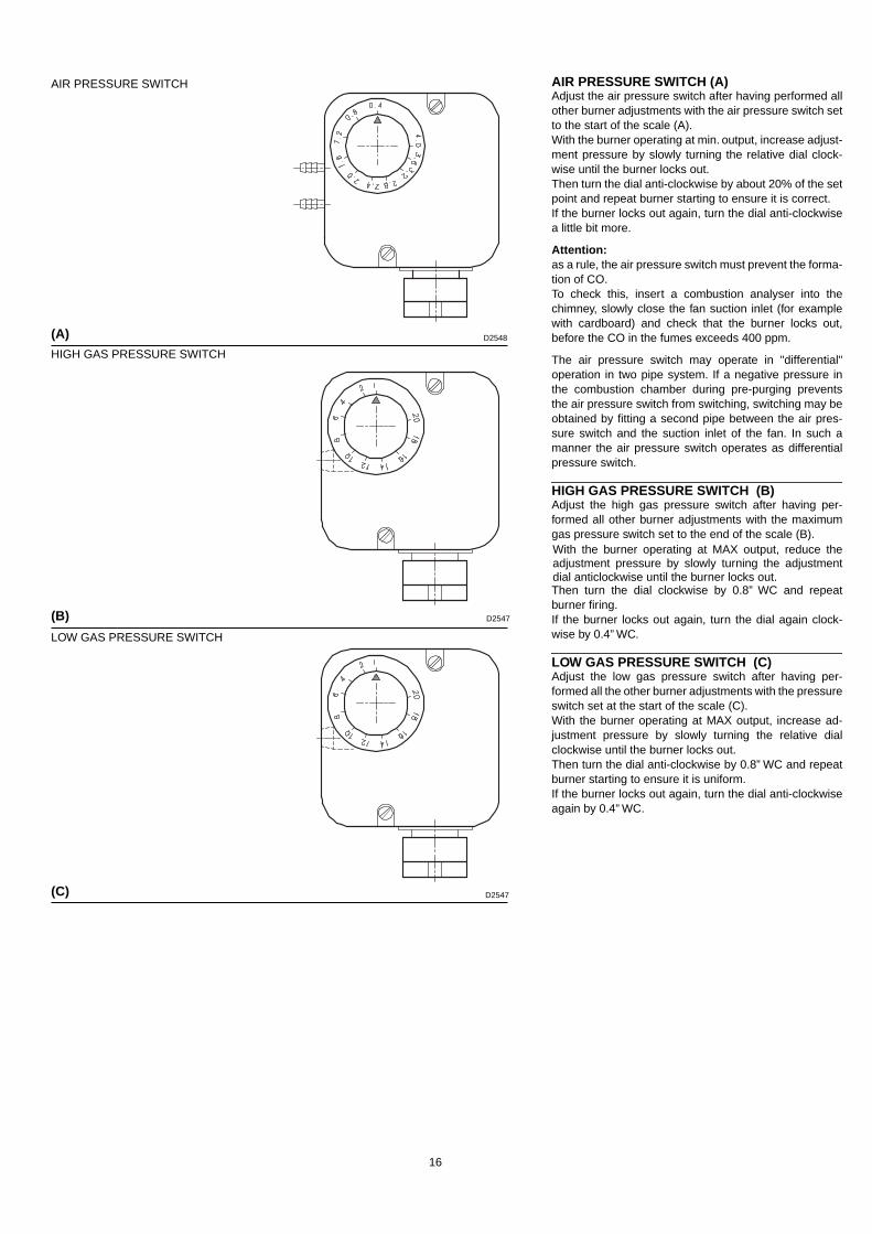
AIR PRESSURE SWITCH (A)Adjust the air pressure switch after having performed allother burner adjustments with the air pressure switch setto the start of the scale (A).With the burner operating at min. output, increase adjust-ment pressure by slowly turning the relative dial clock-wise until the burner locks out.Then turn the dial anti-clockwise by about 20% of the setpoint and repeat burner starting to ensure it is correct.If the burner locks out again, turn the dial anti-clockwisea little bit more.
Attention:as a rule, the air pressure switch must prevent the forma-tion of CO.To check this, insert a combustion analyser into thechimney, slowly close the fan suction inlet (for examplewith cardboard) and check that the burner locks out,before the CO in the fumes exceeds 400 ppm.
The air pressure switch may operate in "differential"operation in two pipe system. If a negative pressure inthe combustion chamber during pre-purging preventsthe air pressure switch from switching, switching may beobtained by fitting a second pipe between the air pres-sure switch and the suction inlet of the fan. In such amanner the air pressure switch operates as differentialpressure switch.
HIGH GAS PRESSURE SWITCH (B)Adjust the high gas pressure switch after having per-formed all other burner adjustments with the maximumgas pressure switch set to the end of the scale (B).With the burner operating at MAX output, reduce theadjustment pressure by slowly turning the adjustmentdial anticlockwise until the burner locks out.Then turn the dial clockwise by 0.8” WC and repeatburner firing.If the burner locks out again, turn the dial again clock-wise by 0.4” WC.
LOW GAS PRESSURE SWITCH (C)Adjust the low gas pressure switch after having per-formed all the other burner adjustments with the pressureswitch set at the start of the scale (C).With the burner operating at MAX output, increase ad-justment pressure by slowly turning the relative dialclockwise until the burner locks out.Then turn the dial anti-clockwise by 0.8” WC and repeatburner starting to ensure it is uniform.If the burner locks out again, turn the dial anti-clockwiseagain by 0.4” WC.
(A)
(B)
AIR PRESSURE SWITCH
(C)
HIGH GAS PRESSURE SWITCH
LOW GAS PRESSURE SWITCH
D2548
D2547
D2547

17
MAINTENANCE
CombustionThe optimum calibration of the burner requires an analy-sis of the flue gases. Significant differences with respectto the previous measurements indicate the points wheremore care should be exercised during maintenance.
Gas leaksMake sure that there are no gas leaks on the pipeworkbetween the gas meter and the burner.
Flame inspection windowClean the flame inspection window (A).
Combustion headOpen the burner and make sure that all components ofthe combustion head are in good condition, notdeformed by the high temperatures, free of impuritiesfrom the surroundings and correctly positioned. If indoubt, disassemble the elbow fitting 7)(C).
Nozzles (fuel oil)Do not clean the nozzle orifices. The nozzle filters how-ever may be cleaned or replaced as required.Replace the nozzles every 2-3 years or whenever nec-essary. Combustion must be checked after the nozzleshave been changed.
UV scannerClean the glass cover from any dust that may haveaccumulated. The scanner 1)(B) is held in position by apressure fit and can therefore be removed by pulling itoutward forcefully.
Flexible hoses (fuel oil)Check to make sure that the flexible hoses are still ingood condition and that they are not crushed or other-wise deformed.
BurnerCheck for excess wear or loose screws. Also make surethat the screws securing the electrical leads in theburner connections are fully tightened.Clean the outside of the burner.
CombustionAdjust the burner if the combustion values found at thebeginning of the operation do not comply with the regu-lations in force, or at any rate, do not correspond to goodcombustion.
TO OPEN THE BURNER (C):- Switch off the electrical power- Loosen screws 1) and withdraw the cover 2)- Disengage the swivel coupling 7) from the graduated
sector.- Disconnect the light-oil pipes.- Remove screws 3) and pull the burner back by about
4” on the slide bars. Disconnect the electrode leadsand then pull the burner fully back.
Now extract the internal part 5) after having removed thescrew 6).
TO CLOSE THE BURNER (C):- Push the burner until it is about 4” from the sleeve.- Re-connect the leads and slide in the burner until it
comes to a stop. - Refit screws 3) and pull the leads gently out until they
are slightly stretched. - Re-couple the swivel coupling 7) to the graduated sec-
tor. - Reconnect the light-oil pipes.
(A)
(B)
(C)
FLAME INSPECTION WINDOW
D484
UV SCANNER
OPENING THE BURNER
D2432
D2433
1
18
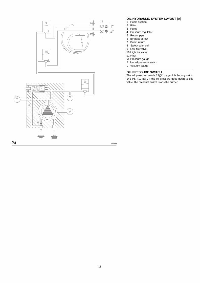
OIL HYDRAULIC SYSTEM LAYOUT (A)1 Pump suction2 Filter3 Pump4 Pressure regulator5 Return pipe6 By-pass screw7 Pump return8 Safety solenoid9 Low fire valve10 High fire valve11 FilterM Pressure gaugeP low oil pressure switchV Vacuum gauge
OIL PRESSURE SWITCHThe oil pressure switch 22)(A) page 4 is factory set to145 PSI (10 bar). If the oil pressure goes down to thisvalue, the pressure switch stops the burner.
(A) D2592

19
Field Wiring Diagram RLS 70 - 100 - 130 With burner mounted Siemens LFL control
Factory Wiring Diagram RLS 70 - 100 - 130With burner mounted Siemens LFL controlSee attached insert for wiring diagram
D2316
RLS 70 RLS 100 RLS 130
208 -230 V
460 V 575 V208 -230 V
460 V 575 V208 -230 V
460 V 575 V
F1 A T10 T6 T6 T15 T10 T6 T15 T10 T10
S1 AWG 14 14 14 14 14 14 14 14 14
F2 A T6 T6 T4 T6 T6 T4 T6 T6 T4
S2 AWG 14 14 14 14 14 14 14 14 14
Fuses and wire size layout (A), see table (B).Wire size when not indicated: AWG18
Key to layouts (A)IN - Burner manual stop switchMB - Burner terminal stripMQ - Panel terminal stripH1 - Adjustment valve signalH2 - Pilot valve signalH3 - Power on signalH4 - Permission okH5 - Remote lock-out signalH6 - Remote motor lock-out signalPG - Low gas pressure switchPS - Remote lock-out resetOC2 - 2 stage controlOC - Operating controlHL - High limit.VP - Pilot valveVPS - Pilot valve (safety)VR - Adjustment valveVS - Safety valve
NOTES• The setting of the thermal overload must be according to the total
burner amperage draw.
• The RLS 70-100-130 burners leave the factory preset for 208-230V power supply. If 460 V power supply is used, change the fanmotor connection from delta to star and change the setting of thethermal overload as well.
• The RLS 70-100-130 burners have been type-approved for inter-mittent operation. This means they should compulsorily bestopped at least once every 24 hours to enable the control box tocheck its own efficiency at start-up. Burner halts are normally pro-vided for automatically by the boiler load control system.If this is not the case, a time switch should be fitted in series to INto provide for burner shut-down at least once every 24 hours.
(A) (B)
20
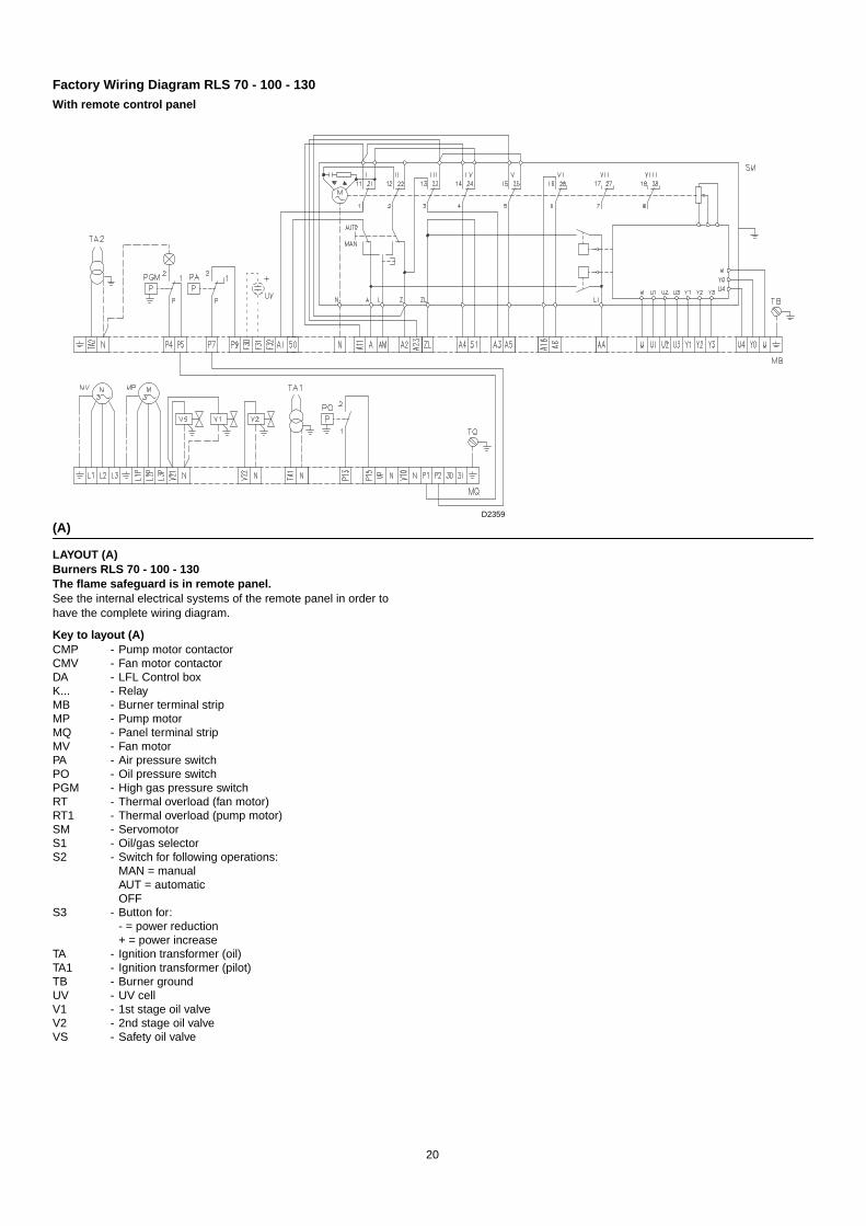
Factory Wiring Diagram RLS 70 - 100 - 130With remote control panel
D2359
LAYOUT (A) Burners RLS 70 - 100 - 130The flame safeguard is in remote panel.See the internal electrical systems of the remote panel in order to have the complete wiring diagram.
Key to layout (A)CMP - Pump motor contactorCMV - Fan motor contactorDA - LFL Control boxK... - RelayMB - Burner terminal stripMP - Pump motorMQ - Panel terminal stripMV - Fan motorPA - Air pressure switchPO - Oil pressure switchPGM - High gas pressure switchRT - Thermal overload (fan motor)RT1 - Thermal overload (pump motor)SM - ServomotorS1 - Oil/gas selectorS2 - Switch for following operations:
MAN = manualAUT = automaticOFF
S3 - Button for:- = power reduction+ = power increase
TA - Ignition transformer (oil)TA1 - Ignition transformer (pilot)TB - Burner groundUV - UV cellV1 - 1st stage oil valveV2 - 2nd stage oil valveVS - Safety oil valve
(A)
21
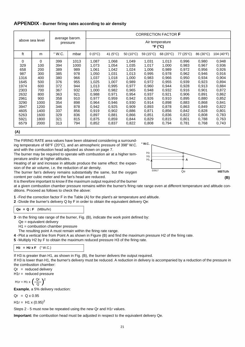
The FIRING RATE area values have been obtained considering a surround-ing temperature of 68°F (20°C), and an atmospheric pressure of 398” W.C.and with the combustion head adjusted as shown on page 7.The burner may be required to operate with combustion air at a higher tem-perature and/or at higher altitudes.Heating of air and increase in altitude produce the same effect: the expan-sion of the air volume, i.e. the reduction of air density.The burner fan's delivery remains substantially the same, but the oxygencontent per cubic meter and the fan's head are reduced. It is therefore important to know if the maximum output required of the burnerat a given combustion chamber pressure remains within the burner's firing rate range even at different temperature and altitude con-ditions. Proceed as follows to check the above:
1 -Find the correction factor F in the Table (A) for the plant's air temperature and altitude.2 -Divide the burner's delivery Q by F in order to obtain the equivalent delivery Qe:
3 - In the firing rate range of the burner, Fig. (B), indicate the work point defined by:Qe = equivalent deliveryH1 = combustion chamber pressureThe resulting point A must remain within the firing rate range.
4 -Plot a vertical line from Point A as shown in Figure (B) and find the maximum pressure H2 of the firing rate.5 -Multiply H2 by F to obtain the maximum reduced pressure H3 of the firing rate.
If H3 is greater than H1, as shown in Fig. (B), the burner delivers the output required.If H3 is lower than H1, the burner's delivery must be reduced. A reduction in delivery is accompanied by a reduction of the pressure inthe combustion chamber:Qr = reduced deliveryH1r = reduced pressure
Example , a 5% delivery reduction:
Qr = Q x 0.95
H1r = H1 x (0.95)2
Steps 2 - 5 must now be repeated using the new Qr and H1r values.
Important: the combustion head must be adjusted in respect to the equivalent delivery Qe.
Qe = Q : F (MBtu/hr)
H3 = H2 x F (“ W.C.)
Qe MBTU/h
A
H2
H1H3
“ W.C.
(B)
D2617
APPENDIX - Burner firing rates according to air density
above sea levelaverage barom.
pressure
CORRECTION FACTOR F
Air temperature°F (°C)
ft m “ W.C. mbar 0 (0°C) 41 (5°C) 50 (10°C) 59 (15°C) 68 (20°C) 77 (25°C) 86 (30°C) 104 (40°F)
0329658987
131616451974230326322961329039474605526359216579
0100200300400500600700800900
100012001400160018002000
399394389385380376372367363358354346337329321313
10131000989978966955944932921910898878856836815794
1,0871,0731,0611,0501,0371,0251,0131,0000,9880,9770,9640,9420,9190,8970,8750,852
1,0681,0541,0421,0311,0181,0070,9950,9820,9710,9590,9460,9250,9020,8810,8590,837
1,0491,0351,0241,0131,0000,9890,9770,9650,9540,9420,9300,9090,8860,8660,8440,822
1,0311,0171,0060,9950,9830,9720,9600,9480,9370,9260,9140,8930,8710,8510,8290,808
1,0131,0000,9890,9780,9660,9550,9440,9320,9210,9100,8980,8780,8560,8360,8150,794
0,9960,9830,9720,9620,9500,9390,9280,9160,9060,8950,8830,8630,8420,8220,8010,781
0,9800,9670,9560,9460,9340,9230,9130,9010,8910,8800,8680,8490,8280,8080,7880,768
0,9480,9360,9260,9160,9040,8940,8840,8720,8620,8520,8410,8220,8010,7830,7630,743
(A)
H1r = H1 x ( )Qr
Q
2

22
FLAME SIGNAL MEASUREMENTMin value for a good signal: 70 µA.If the value is lower, it can be due to:• Worn scanner;• Low current;• Bad set up of the burner.In order to measure the current, use a microammeter of100 µA c.c., connected to the scanner, as in the dia-gram, with a capacitor of 100 µF - 1V c.c. at the samelevel of the instrument. See fig. (A).
OPERATION LAYOUTSee fig. (B).
Switching times are given in seconds, in the burner star-tup sequence.
Legend for the timest1 Pre-purge time with air damper opent2 Safety timet3 Pre-ignition time, short (ignition transformer on
terminal 16)t4 Interval between start of t2 and release of valve
at terminal 19t5 Interval between end of t4 and release of load
controller or valve at terminal 20t5 Running time of air damper into OPEN positiont6 Running time of air damper into low-flame posi-
tion (MIN)t7 Permissible after-burn time t8 Interval until OPEN command for the air damper
is given t9 Running time of pilot
FIRING FAILUREIf the burner does not fire, it locks out within 2.5 secondsfrom opening the pilot valve and then within 5 secondsfrom opening the main valves.
BURNER FLAME GOES OUT DURING OPERA-TIONIf the flame should accidentally go out during operation,the burner will lock out within 1s.
LFL 1.335 Series 01
t1t2t3t4t5
37.52.55
25optional
t6t7t8t9
optional155
16
(A)D1143
(B)
Full modulation
(C)
High - Low
D2273
D2274

23
Control program under fault conditions and lock-out indication
In case of any disturbance, the sequence mechanism stops and with it the lock-out indicator. The symbol above the reading mark of the indicator gives the type of disturbance:
No start , e.g. because one contact is not closed. Lock-out during or after control program sequence due to extraneous light (e.g. non-extinguished flames, leaking fuel valves, defects in the flame supervision circuit, etc.).
Interruption of startup sequence , because the OPEN signal has not been delivered to terminal 8 by cam 1 (gas) or cam 4 (oil). Terminals 6, 7 and 14 remain under voltage until the fault has been corrected!
Lockout , because there is no air pressure indication at the beginning of air pressure control.Every air pressure failure after this moment in time leads to lock-out, too!
Lock-out due to a fault in the flame supervision circuit.
Interruption of startup sequence , because the position signal for the low-flame position has not been delivered to terminal 8 by cam 3 (gas) or cam 5 (oil). Terminals 6, 7 and 14 remain under voltage until the fault has been corrected!
Lock-out , because no flame signal is present after completion of the (1st) safety time.
Lock-out , because no flame signal has been received on completion of the 2nd safety time (flame signal of the main flame with interrupted pilot burners).
Lock-out , because the flame signal has been lost during burner operation.
If lock-out occurs at any other moment in time between the start and the pre-ignition wich is not marked by a symbol, this is usually caused by a premature, i.e. faulty flame signal, e.g. caused by a self-igniting UV tube.
P
1
2
24
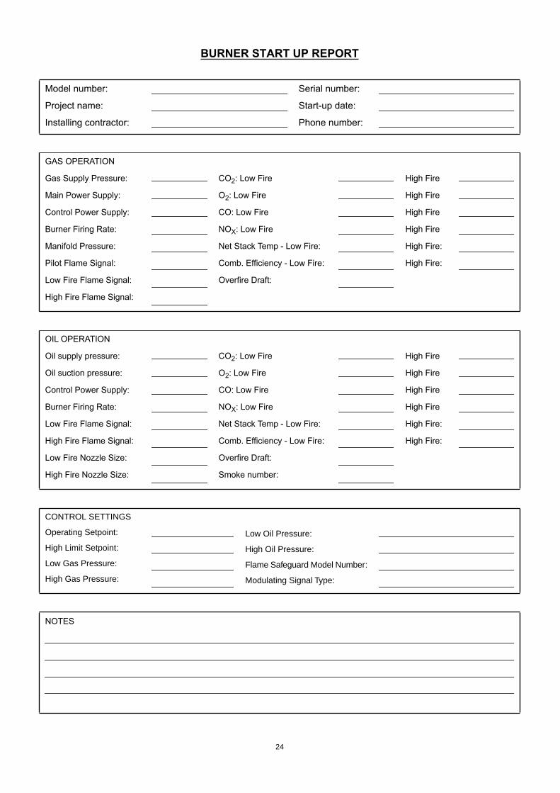
BURNER START UP REPORT
Model number:
Project name:
Installing contractor:
Serial number:
Start-up date:
Phone number:
GAS OPERATION
Gas Supply Pressure:
Main Power Supply:
Control Power Supply:
Burner Firing Rate:
Manifold Pressure:
Pilot Flame Signal:
Low Fire Flame Signal:
High Fire Flame Signal:
CO2: Low Fire
O2: Low Fire
CO: Low Fire
NOX: Low Fire
Net Stack Temp - Low Fire:
Comb. Efficiency - Low Fire:
Overfire Draft:
High Fire
High Fire
High Fire
High Fire
High Fire:
High Fire:
OIL OPERATION
Oil supply pressure:
Oil suction pressure:
Control Power Supply:
Burner Firing Rate:
Low Fire Flame Signal:
High Fire Flame Signal:
Low Fire Nozzle Size:
High Fire Nozzle Size:
CO2: Low Fire
O2: Low Fire
CO: Low Fire
NOX: Low Fire
Net Stack Temp - Low Fire:
Comb. Efficiency - Low Fire:
Overfire Draft:
Smoke number:
High Fire
High Fire
High Fire
High Fire
High Fire:
High Fire:
CONTROL SETTINGS
Operating Setpoint:
High Limit Setpoint:
Low Gas Pressure:
High Gas Pressure:
Low Oil Pressure:
High Oil Pressure:
Flame Safeguard Model Number:
Modulating Signal Type:
NOTES


1-800-4-RIELLO
1-800-474-3556
www.riello-burners.com
35 Pond Park RoadHingham, Massachusetts,U.S.A. 02043
2165 Meadowpine Blvd. Mississauga, Ontario,
Canada L5N 6H6