dual-axis solar tracker using light dependent resistor
TRANSCRIPT

“©Daffodil International University”
Dual-axis Solar Tracker Using Light Dependent
Resistor & Microcontroller
SUBMITTED BY:
Apurba Halder
I.D.:153-33-2958
Supervised by
SHOEL RANA
Lecturer
Department of EEE
Department Of Electrical And Electronic Engineering
Faculty Of Engineering
Daffodil International University

“©Daffodil International University”
Credit of Transmittal
7th August, 2019
To
The Supervisor
department of EEE
Daffodil International University
Dattapara, Ashulia, Savar, Dhaka.
Sub.: Sub class of Project Repair
Sir,
Pleased at found enclosed the project report entitled “Design & Construction of Dual-axis Solar
Tracker Using Light Dependent Resistor & Microcontroller”.
The study has been carried out in success of the requirements for the degree of Bachelor of
Science in Electrical and Electronic Engineering.
In carrying out study, we have followed advice and collected
Required information from several text books, reference books, web sites and other sources.
We think you will find it useful and informative; we would be glad to furnish you
explanations or clarifications if required.
Sincerely yours,
_ _ _ _ _ _ _ _ _ _ _ _ _ _
Apurba Halder
I.D:153-33-2958

“©Daffodil International University”
Annunciation
We do hereby declare solemnly hereby that the work presented in this report entitled “Design
& Construction of Dual-axis Solar Tracker Using Light Dependent Resistor &
Microcontroller.
In completing the investigation, we have pursued boss' recommendation and gathered
Required data from a few course readings, reference books, sites and different sources. We
figure you will think that it valuable and educational; we would be happy to outfit you
clarifications or illuminations whenever required.
.
Authors
Apurba Halder
I.D:153-33-2958
“©Daffodil International University”
DAFFODIL INTERNATIONAL UNIVERSITY
Certificate
This to certify that the response entitled “Design & Construction of Dual-axis Solar Tracker
Using Light Dependent Resistor & Microcontroller” is the valid record of the work done
by Apurba Halder, for some fruition of the requirement of the degree of B.Sc. in Electrical
and Electronic Engineering (EEE) from Daffodil International University.
This work has been complete under my leading and is a bonafide file of valid works complete
successfully.
Countersignature
-----------------------------------
Sohel Rana
Lecturer
Department of EEE
Daffodil International University iv
v
ABSTRACT
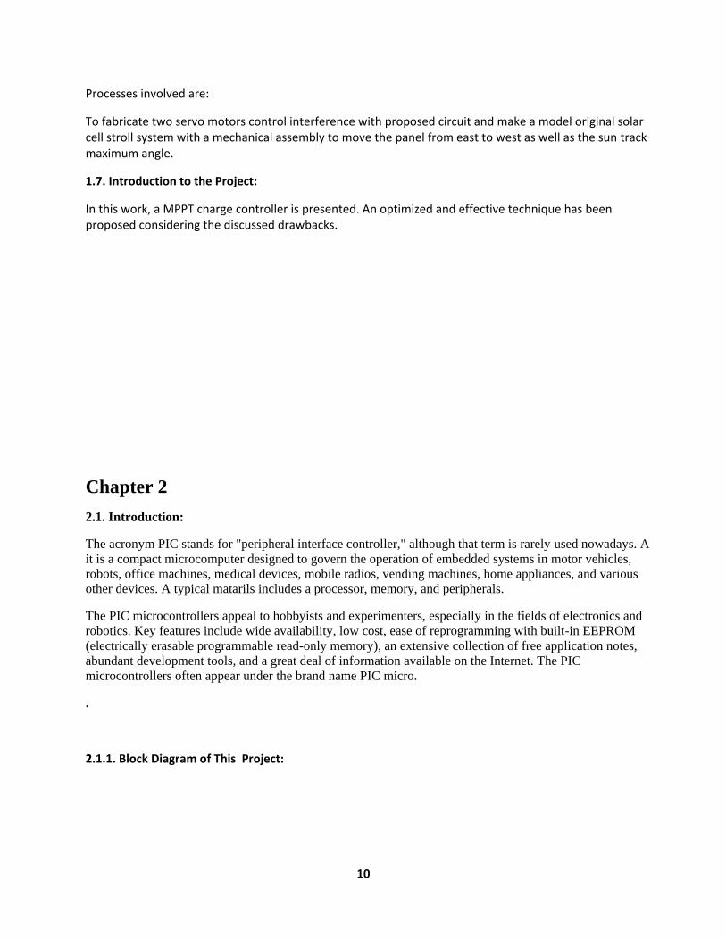
The above figure is a circuit diagram of 2x Solar Panel Tracker which build of a voltmeter array, a microprocessor, solar panel, axis sensor, display, survey motor and battery. When sun lights heat the solar panel, then it started the current flow into the solar panel, which used to charge the batteries. Since, here we are using 2x solar panel, we can heat it all day long by the sun rays and charge the batteries as well. When the charge is fulfilled then the microprocessor signals to the charge controller, and then the battery representation become off. The panel along with the sun we have used an axis sensor, and for this we have used four LDR. To rotate in X and Y axis we have used LDR1, LDR2, LDR3; and LDR4 calculate the power of light and gives the micro power; the micro power survey motor gives the PWM signal and that rotate the panel board in the right direction. LCD display shows battery charging, low voltage, full representation as micro power unit.
TABLE OF CONTENTS
DECLARATION i
APPROVAL ii
ACKNOWLEDGEMENT iii
Certificate vi
ABSTRACT vi
Chapter 1 11
1.1. Introduction 11
1.3 destiny Scope of This Study 12
1.3.1. recommendation 12
1.4. Restriction of the Study 13
1.5. Convenience over traditionary Method 13
1.6. Objective of this Work 13
1.6.1. Basic objectives 13
1.6.2. Secondary Objective 13

vi
1.7. Introduction to this Thesis 14
Chapter 2
2.1. Introducti 14
2.1.1. Block Diagram of This Proposed Project 14
2.1.2. The Model of the Project 15
2.2. Solar panel 16
2.3. Photovoltaic cell model 17
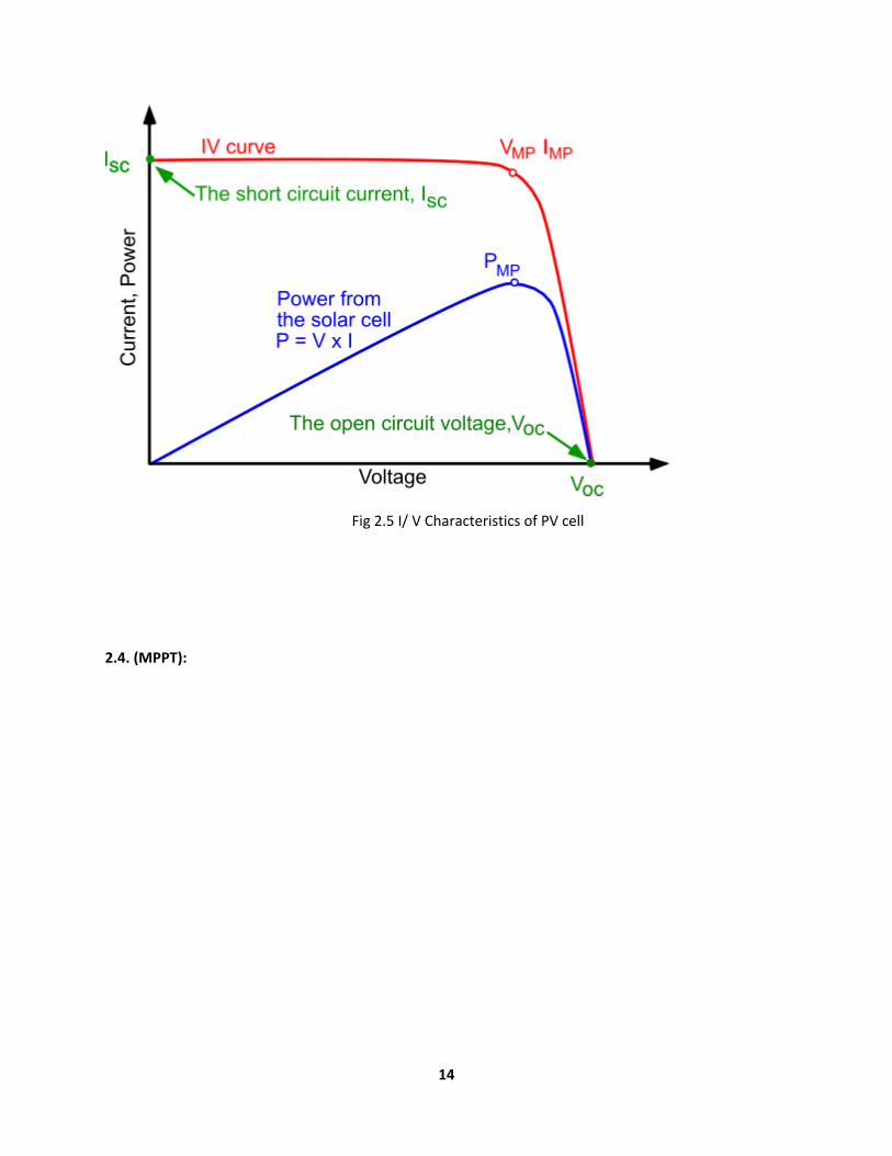
2.3.1. IV curve for a PV cell 18
2.4 Maximum Power Point 19
2.4.1 Designed project 20
Chapter 3
Title of Chapter 3
3.1.1. LDR 21
3.1.2 The Design and implementation of using Four LDRs 22
3.1.3 The minimum light detectable Equation 23
3.2. LCD (2 Line 16 Carriers) 23
3.2.2. Pin Features 24
3.2.3. Pin Description 25
3.3. Servo Motor 26
3.3.1. Components of SG-90 : 26
3.3.2. Servo Mechanism: 27
3.3.4. Motor Control: 27
3.5 L7805CV Linear Voltage Regulator 30
3.5.1 L7805CV OPERATION 31
3.4.4. The Features of PIC16F877: 37
3.5. Voltage regulator 39
3.5.1. Pin Description:
Chapter 4
4.1 Capacitor: 41
4.1 The Designing Tools: 41
4.2. Soldering wire: 41
4.3. Crystal: 42
vii
4.3.1 .Heading 44
5.1. Discussion: 44
5.2. Suggestion for Future work: 45
5.2.1. Development of microcontroller: 45
5.2.2. Development of MPPT system & PV panels: 45
CONCLUSION 45
REFERENCES 46
8
Chapter 1
Introduction
1. 1. Introduction: It’s only for the high cost of power grid building and maintains. This vast quantity of energy crisis can be meeting up by renewable energy across the developing world. During this system embedded system plays a significant role. Inaudible sensors works on a principle almost like radiolocation instrument that evaluates quality of my project. Sensors calculate the quantity between causing the signal In PV power systems maximum power point trackers (MPPTs) has an important role. It’s minimizing the output power of a PV system and also the arrow efficiency as well as its cost is lower than the other power system. An important characteristic of solar panels is that the available maximum power is provided only in a single operating point given by a localized voltage and current known, called Maximum Power Point (MPP). Another problem is that the position of this point is not fixed but it moves according to the irradiance, the temperature and load. In this project we develop a module based on the incremental conductance method. [1-3]
1. To dimension a distance in any obstacle.
2 A simple circuit and find a fitting hardware for this project
1.3. Future scope:
In future, solar energy will be very important source. So, using MPPT solar charge controller can generate a huge amount of current successfully. In this way, the cost of the production can also be reduced. In a word, it can develop a high power output MPPT system with a low cost .
1.3.2. Recommendation:
Future studies into maximum power point tracking could cover the use of a different DC/DC converter and also some different MPPT algorithm such as Current MPPT (CMPPT) for example, could be implemented. Another extension of this project could be to graph the DC/DC converter in full. A future work can also improve the developed software in order to efficiently use the capabilities of the microcontroller. A final original could then be design and implemented in order to have a final portable prototype for the pannel charger.

9
1.4. Limitations of this study:
1. Computing with several analog system, it is costly.
2. Programming of microcontroller is complex.
3. It depends on temperature and radiation .
1.5. Advantage over traditional methods:
At first it is pollution free and reduces the waste of other using of MPPT increase the system’s efficiency. The LCD Display helps the users to inform about the condition of charge. For microcontroller it’s easy to use and ensures reliability the system.
1.6. Objective of this work:
Some analysis works define a higher steering tool for the visually impaired by consisting of a straightforward walking stick equipped with sensors to allow info regarding the surroundings. GPS technology is integrated with pre-programmed locations to see the best route to be taken. The user will opt for the situation from the set of destinations hold on within the memory and can lead within the correct direction of the stick.
1.6.1. Primary objectives:
AS the cost of traditional current source is increasing day by day, people can take the help of renewable energy. The total system can be used both commercially and household generation. So, people can cover the crisis of electric energy, by their own-self. The total system, ensure the maximum efficiency with a low cost comparing other sources and generation system.
1.6.2. Secondary objectives:
10
Processes involved are:
To fabricate two servo motors control interference with proposed circuit and make a model original solar cell stroll system with a mechanical assembly to move the panel from east to west as well as the sun track maximum angle.
1.7. Introduction to the Project:
In this work, a MPPT charge controller is presented. An optimized and effective technique has been proposed considering the discussed drawbacks.
Chapter 2
2.1. Introduction:
The acronym PIC stands for "peripheral interface controller," although that term is rarely used nowadays. A
it is a compact microcomputer designed to govern the operation of embedded systems in motor vehicles,
robots, office machines, medical devices, mobile radios, vending machines, home appliances, and various
other devices. A typical matarils includes a processor, memory, and peripherals.
The PIC microcontrollers appeal to hobbyists and experimenters, especially in the fields of electronics and
robotics. Key features include wide availability, low cost, ease of reprogramming with built-in EEPROM
(electrically erasable programmable read-only memory), an extensive collection of free application notes,
abundant development tools, and a great deal of information available on the Internet. The PIC
microcontrollers often appear under the brand name PIC micro.
.
2.1.1. Block Diagram of This Project:
11
Fig2.1
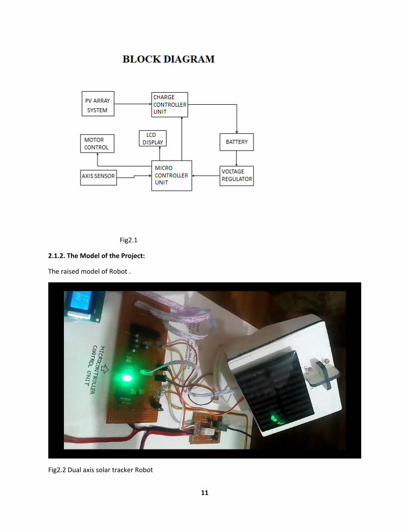
2.1.2. The Model of the Project:
The raised model of Robot .
Fig2.2 Dual axis solar tracker Robot
12
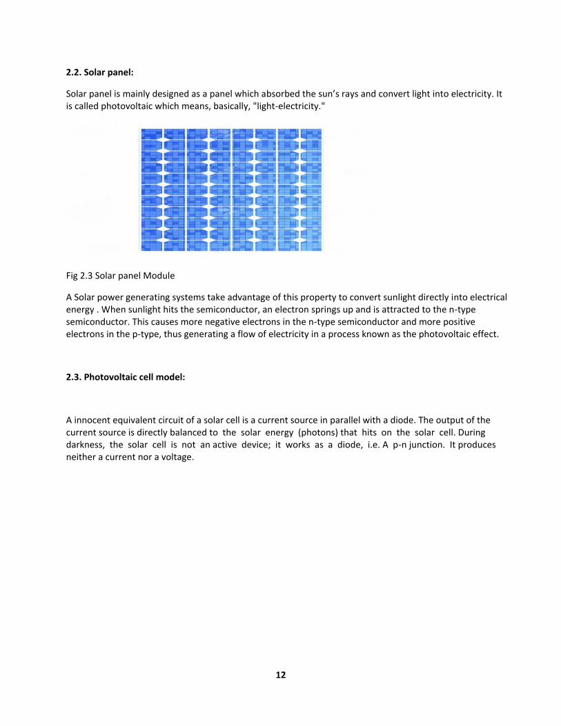
2.2. Solar panel:
Solar panel is mainly designed as a panel which absorbed the sun’s rays and convert light into electricity. It is called photovoltaic which means, basically, "light-electricity."
Fig 2.3 Solar panel Module
A Solar power generating systems take advantage of this property to convert sunlight directly into electrical energy . When sunlight hits the semiconductor, an electron springs up and is attracted to the n-type semiconductor. This causes more negative electrons in the n-type semiconductor and more positive electrons in the p-type, thus generating a flow of electricity in a process known as the photovoltaic effect.
2.3. Photovoltaic cell model:
A innocent equivalent circuit of a solar cell is a current source in parallel with a diode. The output of the current source is directly balanced to the solar energy (photons) that hits on the solar cell. During darkness, the solar cell is not an active device; it works as a diode, i.e. A p-n junction. It produces neither a current nor a voltage.
13
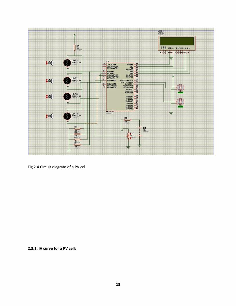
Fig 2.4 Circuit diagram of a PV cel
2.3.1. IV curve for a PV cell:
14
Fig 2.5 I/ V Characteristics of PV cell
2.4. (MPPT):
15
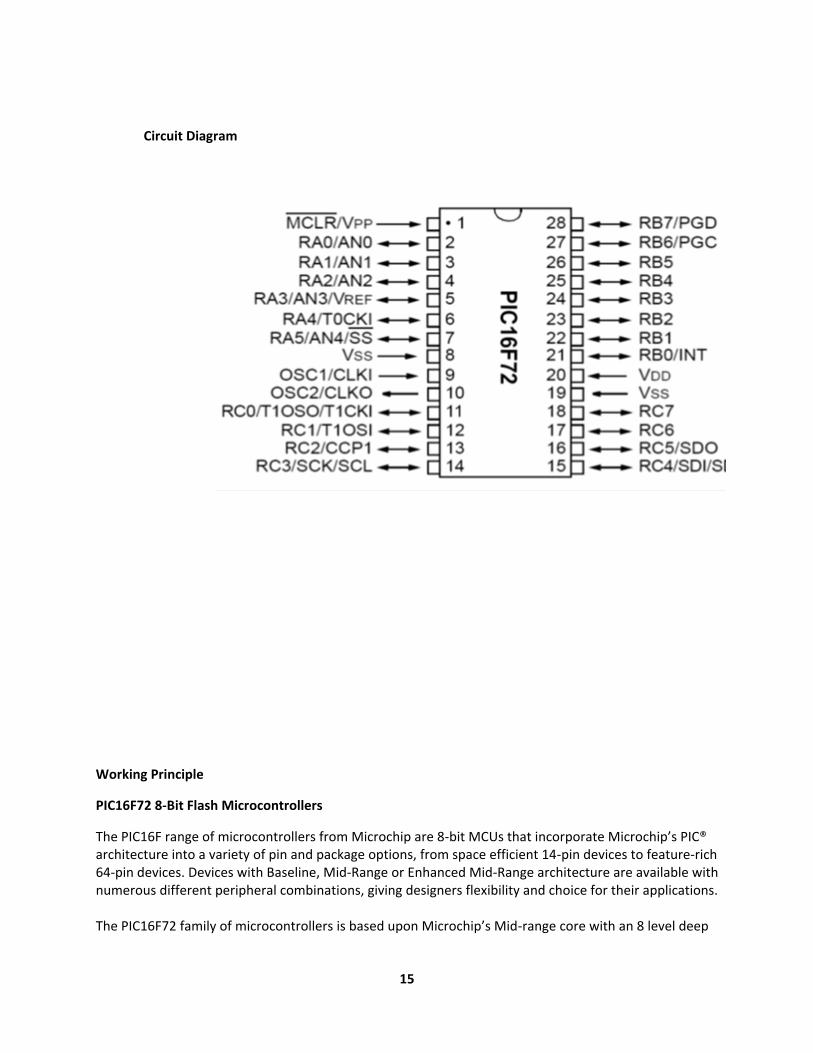
Circuit Diagram
Working Principle
PIC16F72 8-Bit Flash Microcontrollers
The PIC16F range of microcontrollers from Microchip are 8-bit MCUs that incorporate Microchip’s PIC® architecture into a variety of pin and package options, from space efficient 14-pin devices to feature-rich 64-pin devices. Devices with Baseline, Mid-Range or Enhanced Mid-Range architecture are available with numerous different peripheral combinations, giving designers flexibility and choice for their applications. The PIC16F72 family of microcontrollers is based upon Microchip’s Mid-range core with an 8 level deep
16
hardware stack and 35 instructions. These MCUs provide up to 5 MIPS, 3.5 Kbytes program memory and 128 bytes RAM.
PIC16 Microcontrollers
Chapter 3
Components, Design & Implementation
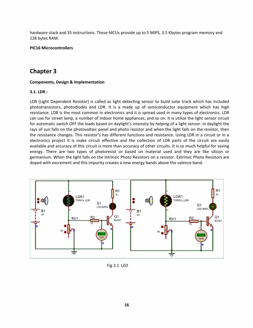
3.1. LDR :
LDR (Light Dependent Resistor) is called as light detecting sensor to build solar track which has included phototransistors, photodiodes and LDR. It is a made up of semiconductor equipment which has high resistance. LDR is the most common in electronics and it is spread used in many types of electronics. LDR can use for street lamp, a number of indoor home appliances, and so on. It is utilize the light sensor circuit for automatic switch OFF the loads based on daylight’s intensity by helping of a light sensor. In daylight the rays of sun falls on the photovoltaic panel and photo resistor and when the light falls on the resistor, then the resistance changes. This resistor’s has different functions and resistance. Using LDR in a circuit or in a electronics project it is make circuit effective and the collection of LDR parts of the circuit are easily available and accuracy of this circuit is more than accuracy of other circuits. It is so much helpful for saving energy. There are two types of photoresist or based on material used and they are like silicon or germanium. When the light falls on the Intrinsic Photo Resistors on a resistor. Extrinsic Photo Resistors are doped with excrement and this impurity creates a new energy bands above the valence band.
Fig 3.1 LED
17
3.1.1. Working Principle of LDR:
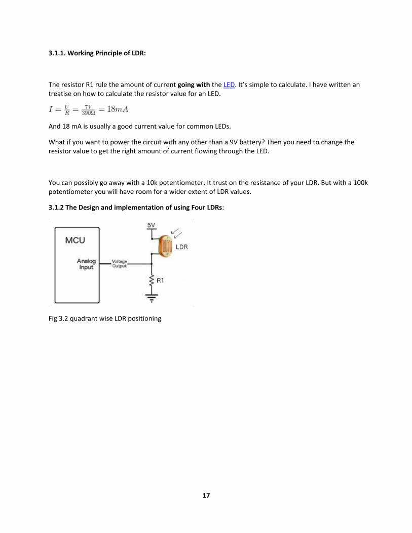
The resistor R1 rule the amount of current going with the LED. It’s simple to calculate. I have written an treatise on how to calculate the resistor value for an LED.
And 18 mA is usually a good current value for common LEDs.
What if you want to power the circuit with any other than a 9V battery? Then you need to change the resistor value to get the right amount of current flowing through the LED.
You can possibly go away with a 10k potentiometer. It trust on the resistance of your LDR. But with a 100k potentiometer you will have room for a wider extent of LDR values.
3.1.2 The Design and implementation of using Four LDRs:
Fig 3.2 quadrant wise LDR positioning

18
Fig 3.3 the Sensing Element and Signal Processing
When it’s black, the LDR has high resistance. This do the voltage at the base of the transistor too low to turn the transistor ON.
Therefore, no current will go from the collector to the emitter of the transistor. All the current will instead of through the LDR.
There are two types of photoresist or based on material used and they are instinctive Photo Resistors and Extrinsic Photo Resistors. Intrinsic Photo Resistors are made up of pure semiconductor devices good silicon or germanium.
3.1.3 The least light detectable Equation:
It is circuit output value
Circuit current 1.23V is the internal band gap reference used by the analog comparator in the UC.

19
3.2. LCD (2 Line 16 Carriers):
LCD screen is an electronic display module. A 16x2 LCD display is very basic module and is good generally used in various devices and circuits. These modules are offer over seven segments and other multi segment LED. The reasons being: LCDs are economical.
Fig 3.4 LCD
A 16x2 LCD means it can display 16 behavior per line and there are 2 such streak. In this LCD each character is displayed in 5x7 pixel matrix. This LCD has two registers, namely, Command and Data. A register which commanded storage the command instructions to the given LCD like initializing it, clearing its screen, setting the cursor whereabouts, controlling display etc. The data register stores the data to be displayed on the LCD.
20
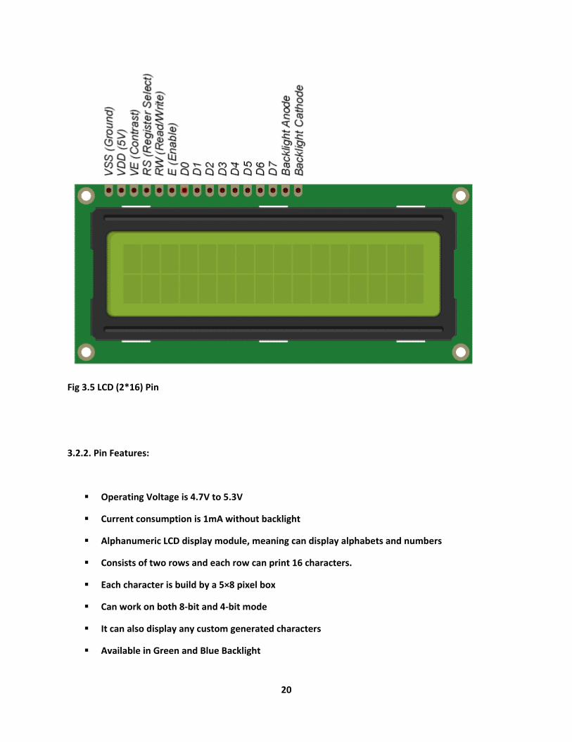
Fig 3.5 LCD (2*16) Pin
3.2.2. Pin Features:
Operating Voltage is 4.7V to 5.3V
Current consumption is 1mA without backlight
Alphanumeric LCD display module, meaning can display alphabets and numbers
Consists of two rows and each row can print 16 characters.
Each character is build by a 5×8 pixel box
Can work on both 8-bit and 4-bit mode
It can also display any custom generated characters
Available in Green and Blue Backlight
21
22
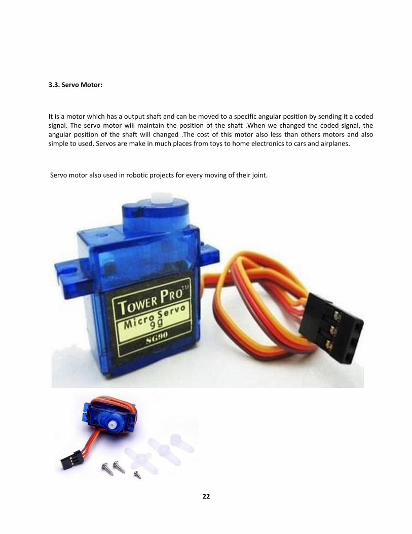
3.3. Servo Motor:
It is a motor which has a output shaft and can be moved to a specific angular position by sending it a coded signal. The servo motor will maintain the position of the shaft .When we changed the coded signal, the angular position of the shaft will changed .The cost of this motor also less than others motors and also simple to used. Servos are make in much places from toys to home electronics to cars and airplanes.
Servo motor also used in robotic projects for every moving of their joint.

23
FIg3.6 Standard Servo Motor SG-90
There are lots of servo motors available in the market and each one has its own speciality and applications.
The following two paragraphs will help you identify the right type of servo motor for your project/system.
Most of the hobby Servo motors operates from 4.8V to 6.5V, the higher the voltage higher the torque we can
achieve, but most commonly they are operated at +5V. Almost all hobby servo motors can rotate only from
0° to 180° due to their gear arrangement so make sure you project can live with the half circle if no, you can
prefer for a 0° to 360° motor or modify the motor to make a full circle. The gears in the motors are easily
subjected to wear and tear, so if your application requires stronger and long running motors you can go with
metal gears or just stick with normal plastic gear.
Next comes the most important parameter, which is the torque at which the motor operates. Again there are
many choices here but the commonly available one is the 2.5kg/cm torque which comes with the Towerpro
SG90 Motor. This 2.5kg/cm torque means that the motor can pull a weight of 2.5kg when it is suspended at a
distance of 1cm. So if you suspend the load at 0.5cm then the motor can pull a load of 5kg similarly if you
suspend the load at 2cm then can pull only 1.25. Based on the load which you use in the project you can
select the motor with proper torque. The below picture will illustrate the same.

24
3.3.1. Components of servo motor SG-90:
Fig 3.7 Physical Construction of Servo SG-90

25
MOTOR SG-90:
It is tiny and light with high output power. This servo can turn nearly 180 degrees and it works just like the standard variety
Specifications:
Weight: 9 g
Dimension: 22.2 x 11.8 x 31 mm approx.
Discontinue torque: 1.8 kg cm
Operating speed: 0.1 s/60 degree
Operating voltage: 4.8 V (~5V)
late band width: 10 μ
Temperature range: 0 ºC – 55 ºC
3.3.2. Servo Mechanism:
In a market there are found two types of servo motor, one are made up of metal gear and another are made up of plastic gear. The metallic one is much heavier than other gear one. The size of metallic gear servo motor is also bigger than plastic gear servo motor.
3.3.4. Motor Control:
Let go consider an example of servomotor that we have given a signal to rotate by an viewpoint of 45° and then stop and wait for further instruction.
The quarry of the DC motor is coupled with another shaft called output shaft, with help of gear assembly. This gear assembly is used to step down the high rpm of the motor's shaft to low rpm at output shaft of the servo system.
26
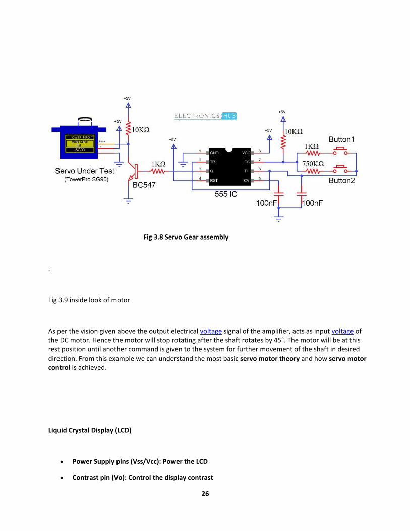
Fig 3.8 Servo Gear assembly
.
Fig 3.9 inside look of motor
As per the vision given above the output electrical voltage signal of the amplifier, acts as input voltage of the DC motor. Hence the motor will stop rotating after the shaft rotates by 45°. The motor will be at this rest position until another command is given to the system for further movement of the shaft in desired direction. From this example we can understand the most basic servo motor theory and how servo motor control is achieved.
Liquid Crystal Display (LCD)
Power Supply pins (Vss/Vcc): Power the LCD
Contrast pin (Vo): Control the display contrast

27
Register Select (RS) pin: Controls where in the LCD's memory you're writing data to
Read/Write (R/W): Selects reading mode or writing mode
Enable pin: Enables writing to the registers
8 data pins (D0 -D7): The states of these pins (high or low) are the bits that you're writing to a register when you write, or the values you're reading when you read.
Backlight (Bklt+ and BKlt-) pins: Turn on/off the LED backlight
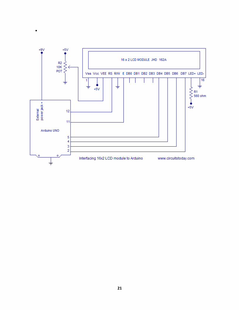
The Hitachi-compatible LCDs can be controlled in two modes: 4-bit or 8-bit. The 4-bit mode requires seven I/O pins from the Arduino, while the 8-bit mode requires 11 pins.
For displaying text on the screen, you can do most everything in 4-bit mode, so in this tutorial we will use 4-bit mode.
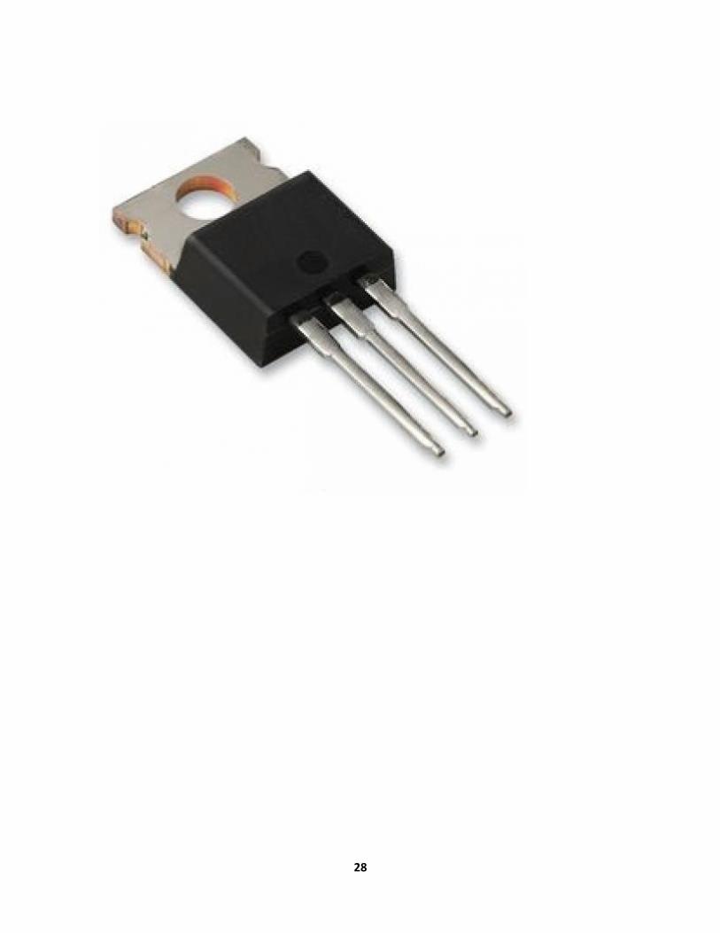
3.5 L7805CV Linear Voltage Regulator
28
29
L7805CV PIN DIAGRAM
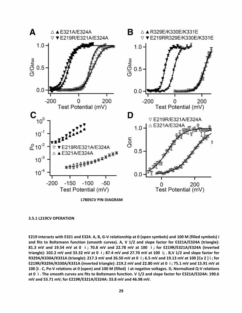
3.5.1 L219CV OPERATION
E219 interacts with E321 and E324. A, B, G-V relationship at 0 (open symbols) and 100 M (filled symbols) i and fits to Boltzmann function (smooth curves). A, V 1/2 and slope factor for E321A/E324A (triangle): 81.3 mV and 19.54 mV at 0 i ; 70.8 mV and 22.78 mV at 100 i ; for E219R/E321A/E324A (inverted triangle): 102.2 mV and 33.32 mV at 0 i ; 87.4 mV and 27.70 mV at 100 i; . B,V 1/2 and slope factor for R329A/K330A/K331A (triangle): 217.3 mV and 26.50 mV at 0 i ; 6.5 mV and 19.13 mV at 100 [Ca 2 ] i ; for E219R/R329A/K330A/K331A (inverted triangle): 219.2 mV and 22.80 mV at 0 i ; 75.1 mV and 15.91 mV at 100 ]i . C, Po-V relations at 0 (open) and 100 M (filled) i at negative voltages. D, Normalized Q-V relations at 0 i . The smooth curves are fits to Boltzmann function. V 1/2 and slope factor for E321A/E324A: 190.6 mV and 53.71 mV; for E219R/E321A/E324A: 33.8 mV and 46.98 mV.
30
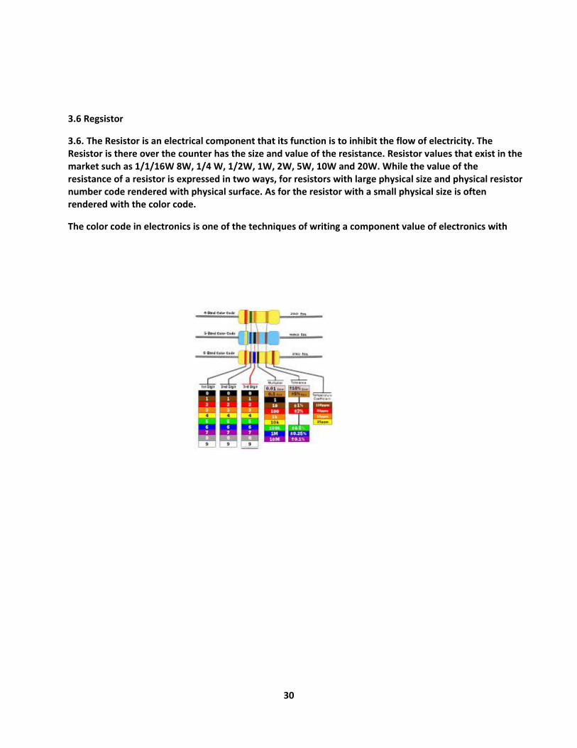
3.6 Regsistor
3.6. The Resistor is an electrical component that its function is to inhibit the flow of electricity. The Resistor is there over the counter has the size and value of the resistance. Resistor values that exist in the market such as 1/1/16W 8W, 1/4 W, 1/2W, 1W, 2W, 5W, 10W and 20W. While the value of the resistance of a resistor is expressed in two ways, for resistors with large physical size and physical resistor number code rendered with physical surface. As for the resistor with a small physical size is often rendered with the color code.
The color code in electronics is one of the techniques of writing a component value of electronics with

31
Fig: 560k ohm
Fig: resistor 3k3 ohm
3.6. A diode permits electrical energy to flow in one instruction just and blocks the flow in the opposite instructions. They might be considered one-way valves and they are used in different circuits, typically as a kind of security. There are different types of diode however their standard functions are the very same.
Signal diodes can likewise be utilized for many other functions within circuits where the “one way” result of a diode may be needed.
Various semiconductor types can be utilized to carry out various functions as an outcome of the properties of these various types.
Semiconductor can be utilized for lots of applications. Signal can likewise be utilized for numerous other functions within circuits where the “one method” impact of a might be needed.
32
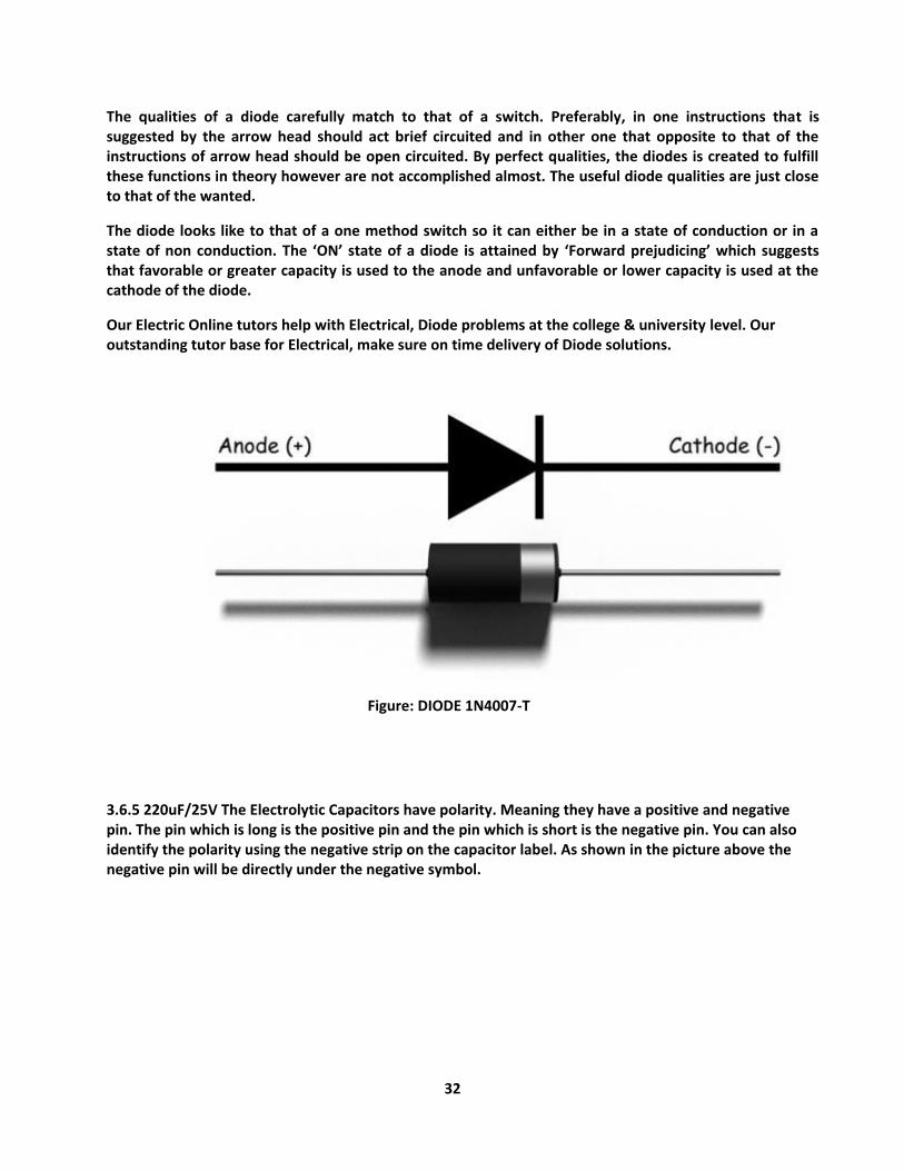
The qualities of a diode carefully match to that of a switch. Preferably, in one instructions that is suggested by the arrow head should act brief circuited and in other one that opposite to that of the instructions of arrow head should be open circuited. By perfect qualities, the diodes is created to fulfill these functions in theory however are not accomplished almost. The useful diode qualities are just close to that of the wanted.
The diode looks like to that of a one method switch so it can either be in a state of conduction or in a state of non conduction. The ‘ON’ state of a diode is attained by ‘Forward prejudicing’ which suggests that favorable or greater capacity is used to the anode and unfavorable or lower capacity is used at the cathode of the diode.
Our Electric Online tutors help with Electrical, Diode problems at the college & university level. Our outstanding tutor base for Electrical, make sure on time delivery of Diode solutions.
Figure: DIODE 1N4007-T
3.6.5 220uF/25V The Electrolytic Capacitors have polarity. Meaning they have a positive and negative pin. The pin which is long is the positive pin and the pin which is short is the negative pin. You can also identify the polarity using the negative strip on the capacitor label. As shown in the picture above the negative pin will be directly under the negative symbol.
33
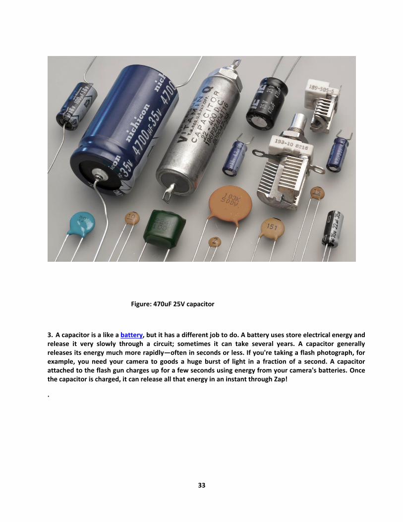
Figure: 470uF 25V capacitor
3. A capacitor is a like a battery, but it has a different job to do. A battery uses store electrical energy and release it very slowly through a circuit; sometimes it can take several years. A capacitor generally releases its energy much more rapidly—often in seconds or less. If you're taking a flash photograph, for example, you need your camera to goods a huge burst of light in a fraction of a second. A capacitor attached to the flash gun charges up for a few seconds using energy from your camera's batteries. Once the capacitor is charged, it can release all that energy in an instant through Zap!
.
34
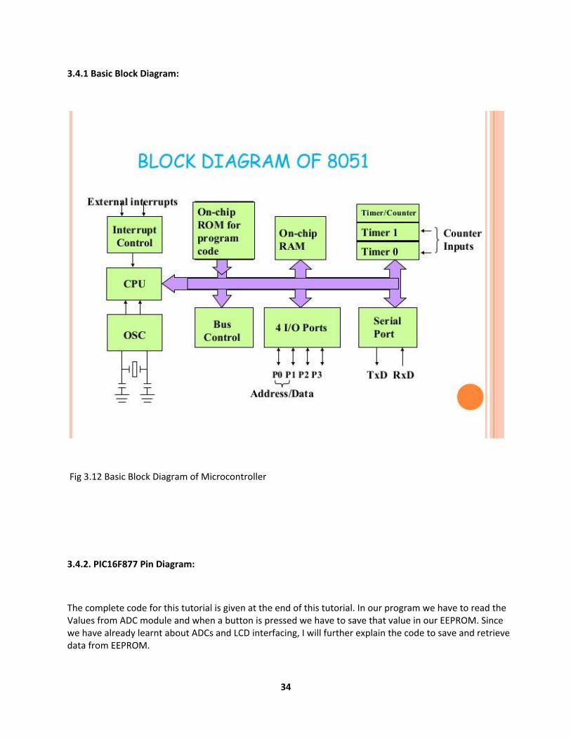
3.4.1 Basic Block Diagram:
Fig 3.12 Basic Block Diagram of Microcontroller
3.4.2. PIC16F877 Pin Diagram:
The complete code for this tutorial is given at the end of this tutorial. In our program we have to read the Values from ADC module and when a button is pressed we have to save that value in our EEPROM. Since we have already learnt about ADCs and LCD interfacing, I will further explain the code to save and retrieve data from EEPROM.
35
According to Datasheet “These devices have 4 or 8K words of program Flash, with an address range from 0000h to 1FFFh for the PIC16F877A”. This means that each EEPROM storage space has an address through which it can be accessed and in our MCU the address starts from 0000h to 1FFFh.
To save a data inside a particular EEPROM address simply use the below line.
eeprom_write(0,adc);
Here “adc” is a variable of type integer in which the data to be saved is present. And “0” is the address of the EEPROM on which our data is saved. The syntax is provided by our XC8 complier hence the registers will be automatically taken care by the compiler.
To retrieve a data that is already stored in EEPROM and save it to a variable the following line of code can be used.
Here, “Sadc” is the variable in which the data from the EEPROM will be saved. And “0” is the address of EEPROM from which we are retrieving the data. The syntax “eeprom_read” is provided by our XC8 complier hence the registers will be automatically taken care by the compiler. The data saved in EEPROM will be in hexadecimal type. Hence we convert them to integer type by prefixing a (int) before the syntax.

36
Fig: 3.13 PIC16F877 Microcontrollers
3.4.4. The Features of PIC16F877:

37
3.5. Voltage regulator:
A voltage Regulator is good works. Here we use IC 7805 voltage superitendence. The voltage source in a circuit may have impatience and would not give the fixed voltage output. The voltage regulator IC preserve the output voltage at a constant value.
Fig 3.16 Voltage Regulator
38
Chapter 4
4.1. Capacitor:
There are different types of capacitors available in the market. Each of them are singularly crafted to service certain way of storing and supplying current. The broadest imparity is based on the type of current the capacitor can be charged with.
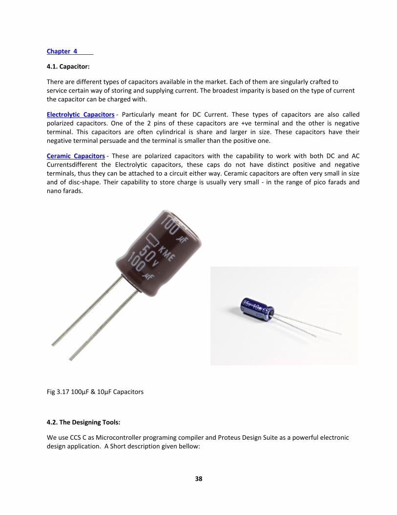
Electrolytic Capacitors - Particularly meant for DC Current. These types of capacitors are also called polarized capacitors. One of the 2 pins of these capacitors are +ve terminal and the other is negative terminal. This capacitors are often cylindrical is share and larger in size. These capacitors have their negative terminal persuade and the terminal is smaller than the positive one.
Ceramic Capacitors - These are polarized capacitors with the capability to work with both DC and AC Currentsdifferent the Electrolytic capacitors, these caps do not have distinct positive and negative terminals, thus they can be attached to a circuit either way. Ceramic capacitors are often very small in size and of disc-shape. Their capability to store charge is usually very small - in the range of pico farads and nano farads.
Fig 3.17 100µF & 10µF Capacitors
4.2. The Designing Tools:
We use CCS C as Microcontroller programing compiler and Proteus Design Suite as a powerful electronic design application. A Short description given bellow:

39
Key Compiler Features:
Readily migrate between all Microchip PIC MCUs devices.
diminish development time with: peripheral drivers and standard C constructs.
output streams with full data formatting to any device or for strings.
Use CCS libraries and object code royalty free
The undivided one-bit type permits the compiler to generate very efficient Bit-oriented code
smoothly define, set-up and manage interrupts.
4.3. Proteus Design Suite:
Proteus is a software bundle for computer-aided design, simulation and design of electronic circuits. It consists of two main parts, the ISIS, the circuit design environment that even the simulator VSM includes, and the ARES, the PCB –Designer
It news a range of design features including:
planned capture
Mixed-mode electronic circuit simulation
Microcontroller simulation
PCB graph with manual and AutoRoute options
Graph-based interest
4.3.1. Soldering wire:
Betel is basically metal wire with a "low" melting point, where low for our motive means low enough to be melted with a soldering iron. For electronics, it is traditionally a mix of tin and lead. When the soldering wire cooled off an electrical connection will conduct. This is getting a good mechanical connection between the wires. The filaments of each wire should be twisted together, behave more like a single entity. First step is to prepare the wires then tinning the wears, next to join the wires and solder splice together.
40
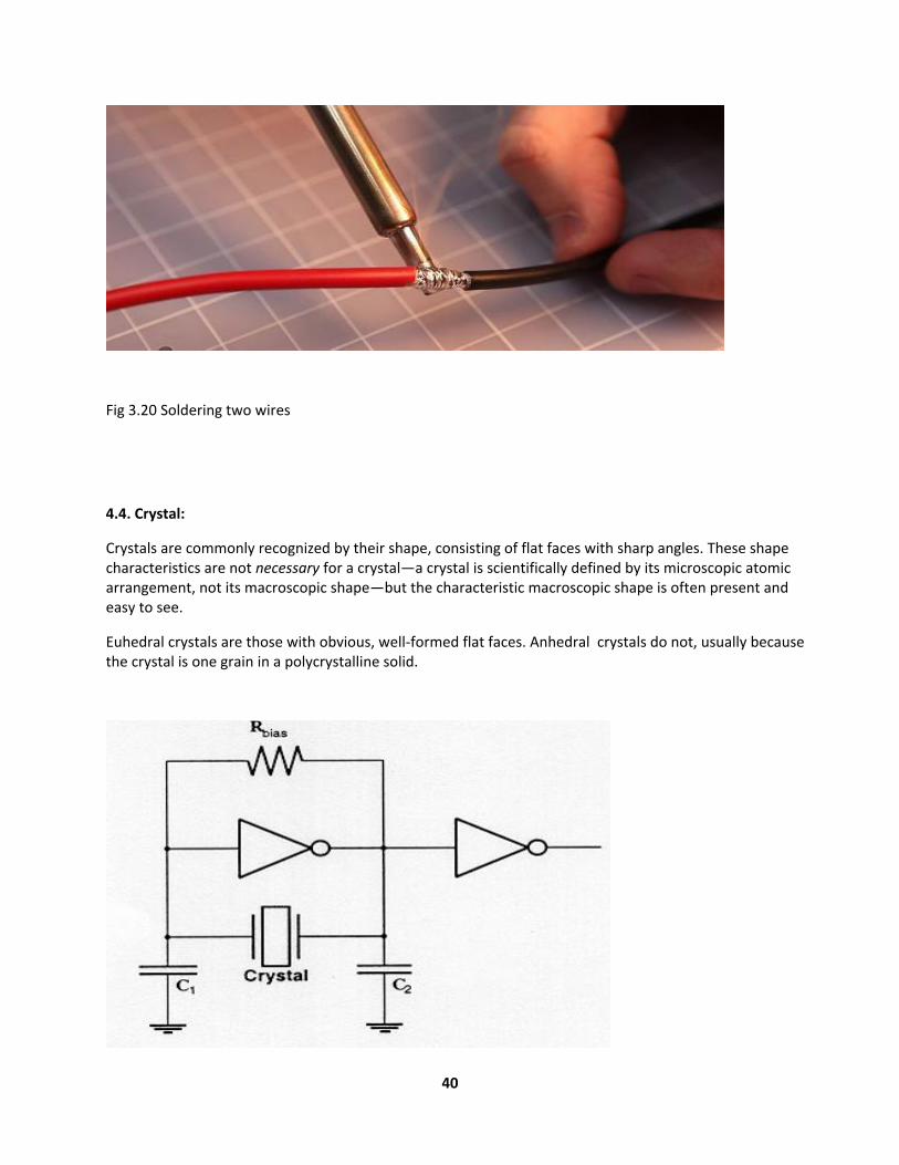
Fig 3.20 Soldering two wires
4.4. Crystal:
Crystals are commonly recognized by their shape, consisting of flat faces with sharp angles. These shape characteristics are not necessary for a crystal—a crystal is scientifically defined by its microscopic atomic arrangement, not its macroscopic shape—but the characteristic macroscopic shape is often present and easy to see.
Euhedral crystals are those with obvious, well-formed flat faces. Anhedral crystals do not, usually because the crystal is one grain in a polycrystalline solid.
41
Fig3.21. Crystal
3.11. Battery (12V Sulfuric Acid Battery):
Chapter 5
5.1. Discussion:
1 MICROCONTROLLER & ITS INTERFACING
2 Topics of Discussion: Microprocessor Definition Working Microprocessor & Human Behaviour
Microcontroller 8051 Definition Microprocessor Vs Microcontroller 8051 Features 9/30/20162Er. Mandeep Singh
3 Topics of Discussion: Block Diagram of 8051 Manufacturers Addressing Modes How to write
program Real World Interfacing Simple I/O concept LCD Interfacing 9/30/20163Er. Mandeep Singh
4 Topics of Discussion: ADC0804 Interfacing Relay Interfacing Stepper Motor Interfacing DC Motor
Interfacing Applications of 8051 Queries 9/30/20164Er. Mandeep Singh
5 Multipurpose Re-Programmable Digital Device is Semiconductor IC 9/30/20165Er. Mandeep Singh
6 Provide desired result to the outer world.
7 Microprocessor(cont.): 9/30/20167Er. Mandeep Singh

42
8 Microprocessor & Human Behaviour: 9/30/20168Er. Mandeep Singh
9 Swiss Knife 9/30/20169Er. Mandeep Singh
10 Microprocessor Vs Microcontroller: 9/30/201610Er. Mandeep Singh
11 Microcontroller 8051 Features: 9/30/201611Er. Mandeep Singh
12 8051 Block Diagram: 9/30/201612Er. Mandeep Singh
13 Manufacturers of 8051: Intel Atmel Phillips Dallas Motorola National Infineon 9/30/201613Er. Mandeep Singh
14 Pin Diagram-8051: 9/30/201614Er. Mandeep Singh
16 Greeting Modes (cont.): Immediate greeting Mode : MOV A, #64H MOV R1, #0FFH Direct Addressing Mode: MOV A, 64H MOV A, 0FFH 9/30/201616Er. Mandeep Singh
17 Addressing Modes (cont.): Register greeting Mode MOV A, R0 MOV R1, A Register A,@R0 MOV @R1,A 9/30/201617Er. Mandeep Singh
18 How to Write Program: 9/30/201618Er. Mandeep Singh
.2. Suggestion for Future work:
The main objective of this project is to achieve the highest performance a solar charge controller using
MPPT system. This system successfully uses MPPT algorithm to reach our goal. Reach a stable, true MPP at
unmoved state instead of oscillating around this point would utilize the system’s efficiency and improve
reliability.
5.2.1. Development of microcontroller:
Microcontroller have went through a silent evolution (invisible). The enlargement can be rightly termed as silent as the impact or application of a microcontroller is not well known to a common user, although microcontroller technology has sustain significant change since early 1970's. Development of some popular microcontrollers is given as follows.
5.2.2. Development of MPPT system & PV panels:
This study propound a binary search-based fault detection system for photovoltaic (PV) modules to
ameliorate the deficiencies in the existing fault detectors for PV module arrays. The raised system applies a
single-chip microcontroller to execute the binary search algorithm. Moreover, to overcome multi-node
voltage detection and reduce the number of integrated circuit components, an analog switch is used to
perform detection channel switching; the detection results are displayed on a software platform developed
using Visual C#. The raised system does not vindicate learning to execute the fault diagnosis of PV module
arrays and has advantages including high accuracy and low construction costs

43
Working Principle
The main controlling part of this solar tracking system is the microcontroller.The program detects and
controls various functions and operations of this project. Light-dependent resistors LDR0 with LDR2
are used as sensors to detect the panel’s position relative to the sun. 3 LDRs are fixed at the edges of
the solar panel along the X and Y axis, and connected to microcontroller. Here LDR0 is common.
LDR0 and LDR1 are used to track horizontal axis (x-axis. As a result, output pin 14 goes high to rotate
motor M1 in one direction(anti-clockwise) and turn the solar. When LDR0 accept more light than
LDR1, it offers lower resistance than LDR1, giving low input to pin 3. As the result, output pin 14 goes
goes low to rotate motor M1 in opposite direction (clockwise) and the solar panel turns. Similarly,
LDR0 and LDR2 track the sun one Y axis.
3.8 CONCLUSION
The proposed dual-axis solar tracking system wish be reliable and accurate throughout the year and
maximize the output power when compared to static system and single axis tracking system. It will be a
good and competitive solution for the market place as it is expected to compete with more complex and
expensive .The results show that the results for measured distance is satisfying for use in the sewer
inspection system being developed. It can also be used for other devices requiring distance assessment of
an object or obstacle. As shown, the system is implementable in the robotic sewer blockage detection
system. The fare blockage from a specified entry point in the sewer pipeline can be calculated by adding
travelled distance by the robotic vehicle and the distance of the obstructive from the robotic vehicle. The
accuracy of distance of blockage will be sufficient for normal practical uses. The rapid increase in energy
demand cannot be resolved easily until there is an alternative way to meet the demand. The micro grid
can undertake to solve this sort of situation in future. Solar, wind and biomass energy is the main source
of energy used for optimizing the overall system and hence to make it efficient..

44
REFERENCES
[1] 2013 Microchip Technology Inc., U.S.A., ISBN: 9781620772164.
[2] IEEE TRANSACTIONS ON ENERGY CONVERSION, VOL. 22, NO. 2, JUNE 2007.
[3] IOSR Journal of Electronics and Communication Engineering (IOSR-JECE), ISSN: 2278-2834-, ISBN: 2278-8735, PP: 27-33.
[4] Australian Energy Research Laboratories (AERL), website. [Online]. Available: http://www.aerl.com.au/hydro-wind-solar-mppt/aerl-mppt-range-history.html
[5] John E. Pfeifer, Fabio A.M. Pereira, Herbert E. Flynn, “ DEVELOPMENT OF A MICROCONTROLLER BASED SOLAR PHOTOVOLTAIC MPPT CHARGE CONTROL SYSTEM Using INCREMENTAL CONDUCTANCE METHOD”,academia.edu(May 15, 2008), Publication number:US20080111517 A1.
[6] Volume 6, 2011, Pages 541–549
[7], M. Ben Amar, Journal of Power and Energy Engineering, Vol.4 No.3, September 2015, DOI: 10.4236/jpee.2014.21004
[8] J. D. P. Pacheco, H. L. Hey, J. IEEE Transactions on Industrial Electronics, (Volume: 55, Issue: 7), July 2008.
[9] Proceedings of the 14th International Middle East Power Systems Conference (MEPCON’10), Cairo University, Egypt, December 19-21, 2010, Paper ID 278.
[10] A. Safari and S. “Simulation and hardware implementation of incremental conductance MPPT with direct control method using Cuk converter,” IEEE Trans. Ind. Electron, vol. 58, pp. 1154–1161, April 2011.
[11] “Case Study of Solar Power Producing Efficiency from a Photovoltaic System”, Open Journal of Energy Efficiency, 4, 45-52. DOI: 10.4236/ojee.2015.43005, Vol.4 No.3, September 2015.
45
[12], H. and Amar, “Design Analysis of DC-DC Converters Connected to a Photovoltaic Generator and Controlled by MPPT for Optimal Energy Transfer throughout a Clear Day”, Journal of Power and Energy Engineering, 2, 27-34. DOI: 10.4236/jpee.2014.21004,Vol.2 No.1, January 2014, PP. 27-34
[13] C. Liu, B. Wu, and R. Cheung, “Advanced algorithm for MPPT control of photovoltaic systems,” in Canadian Solar Buildings Conference Montreal, Solar Buildings Research Network, 2004.
[14] J.-M. Kwon, K.-H. Nam, and B.-H. Kwon, “Photovoltaic power conditioning system with line connection,” Industrial Electronics, IEEE Transactions on, vol. 53, no. 4, pp. 1048– 1054, 2006.
[15] R. Teodorescu, P. Rodriguez, G. Vazquez, and E "A New High-Efficiency Single-Phase Transformer less PV Inverter Topology," IEEE Transactions on Industrial Electronics, vol. 58,pp. 184-191, 2011
[16] Rajesh N.INTERNATIONAL JOURNAL OF ENGINEERING SCIENCES & RESEARCH TECHNOLOGY, ISSN: 2277-9655(I2OR), Publication Impact Factor: 3.785, January, 2016.
THANK YOU

46