dual-axis accelerometer cas200 ...dual-axis accelerometer cas200 technical datasheet...
TRANSCRIPT
© Copyright 2015 Silicon Sensing Systems Limited. All rights reserved. Silicon Sensing is an Atlantic Inertial Systems, Sumitomo Precision Products joint venture company.Specifi cation subject to change without notice.
Dual-Axis Accelerometer
CAS200 Technical Datasheet
Page 1CAS200-00-0100-132 Rev 7
Features• Small (10.4 x 6.0 x 2.2mm)
• Excellent bias repeatability over temperature
• Dual-axis MEMS accelerometer in a hermetically sealed ceramic LCC surface mount package for temperature and humidity resistance
• Five dynamic range options; ±0.85g, ±2.5g, ±10g, ±30g, ±96g
• Analogue and digital (SPI®) outputs for linear acceleration and temperature
• Wide bandwidth (typically 170Hz digital, 250Hz analogue)
• Temperature range -40 to +125ºC
• Low power consumption (3mA Typ) from a 3.3V supply
• Integral temperature sensor
• RoHS compliant
Applications• Aerospace and industrial
• Aircraft AHRS and controls
• Platform stabilisation
• Drilling guidance
• Surveying and mapping
• Land and marine navigation
• Transportation
• Inertial measurement units
• Levelling and tilt sensing
1 General DescriptionGeminiTM is a new family of integrated MEMSaccelerometers from Silicon Sensing, providing high performance dual-axis linear acceleration measurement in a small surface mounted package. It comprises a dual-axis MEMS sensing device with a dedicated control ASIC in a single ceramic LCC package. Sensor data is output via analogue and digital (SPI®) interfaces.
The CAS200 series of parts provides two in-plane axes of linear acceleration sensing and is available in fi ve different dynamic ranges:
• ±0.85g - CAS211• ±2.5g - CAS212• ±10g - CAS213• ±30g - CAS214• ±96g - CAS215
CAS200 is supplied as a PCBA surface mountable standard LCC ceramic packaged device, which is hermetically sealed providing full environmental protection.
Precise linear acceleration sensing is achieved by a Silicon MEMS detector forming an orthogonal pair of sprung masses. Each mass provides the moving plate of a variable capacitance formed by an array of interlaced ‘fi ngers’. This structure also provides critical damping to prevent resonant gain. Linear acceleration results in a change of capacitance which is measured by demodulation of the square wave excitation.
Y
X
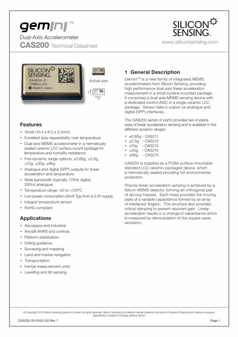
CAS213 - C
Actual size
www.siliconsensing.com
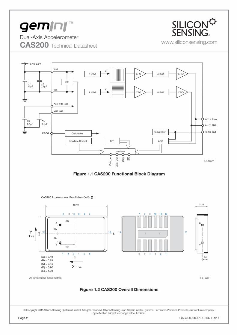
Figure 1.2 CAS200 Overall Dimensions
Figure 1.1 CAS200 Functional Block Diagram
1 2 3 4 5 6
12
1413
11 10 9 8 7
10.40
CAS200 Accelerometer Proof Mass CofG :
(A) = 3.10(B) = 0.95(C) = 3.15(D) = 0.90(E) = 1.00
(C)
(E)
(A)
(B)
(D)
X
Y
X
Y
CL
CL
All dimensions in millimetres.
2.18
6.00
C.G.18580
6 5 4 3 2 1
7
14 13
8 9 10 11 12
Y
X
+ ve
+ve
CAS200-00-0100-132 Rev 7Page 2
© Copyright 2015 Silicon Sensing Systems Limited. All rights reserved. Silicon Sensing is an Atlantic Inertial Systems, Sumitomo Precision Products joint venture company.Specifi cation subject to change without notice.
All dimensions in millimetres.
Dual-Axis Accelerometer
CAS200 Technical Datasheet
XPO
YPO
X Drive
Y Drive
X
Y
Demod
Demod
Temp Sen 1
Vref
ADCBIT
C30.1µF
Temp_Out
Dat
a_In
Dat
a_O
ut
Dcl
k
SS
Vdd
Vss
Acc Y ANA
Acc X ANA
PROG
XP/O
YP/O
Vref_cap
Acc_Vdd_cap
C1 10µF
C20.1µF
C40.1µF
2.7 to 3.6V
C.G.18577
Calibration
Interface Control
Interface
www.siliconsensing.com
Page 3CAS200-00-0100-132 Rev 7
© Copyright 2015 Silicon Sensing Systems Limited. All rights reserved. Silicon Sensing is an Atlantic Inertial Systems, Sumitomo Precision Products joint venture company.Specifi cation subject to change without notice.
Dual-Axis Accelerometer
CAS200 Technical Datasheetwww.siliconsensing.com
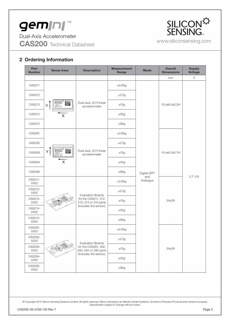
2 Ordering Information Part
NumberSense Axes Description
Measurement Range
ModeOverall
DimensionsSupplyVoltage
mm V
CAS211
Dual-axis, (X,Y) linear accelerometer
±0.85g
Digital SPI®
andAnalogue
10.4x6.0x2.2H
2.7~3.6
CAS212 ±2.5g
CAS213 ±10g
CAS214 ±30g
CAS215 ±96g
CAS291
Dual-axis, (X,Y) linear accelerometer
±0.85g
10.4x6.0x2.7H
CAS292 ±2.5g
CAS293 ±10g
CAS294 ±30g
CAS295 ±96g
CAS211-0302
Evaluation Boards for the CAS211, 212, 213, 214 or 215 parts (includes the sensor).
±0.85g
34x26
CAS212-0302
±2.5g
CAS213-0302
±10g
CAS214-0302
±30g
CAS215-0302
±96g
CAS291-0302
Evaluation Boards for the CAS291, 292, 293, 294 or 295 parts (includes the sensor).
±0.85g
34x26
CAS292-0302
±2.5g
CAS293-0302
±10g
CAS294-0302
±30g
CAS295-0302
±96g
Y
X
CAS213 - C
Y
X
CAS213-C
YYMMLLLXXX
C6
C4
C3 C2
R 4
PL1
IC4
Made In Japan
C4
C6
C2 C3
PL1 IC1
CAS293-1
YYMMLLLXXXMade In Japan

3 Specifi cationUnless otherwise specifi ed the following specifi cationvalues assume Vdd = 3.15 to 3.45V over thetemperature range -40 to +125°C.
3.1 Digital Output Specifi cation
Parameter CAS211 CAS212 CAS213 CAS214 CAS215 Notes
Dynamic range ±0.85g ±2.5g ±10g ±30g ±96g –
Scale factor 33,500lsb/g 11,000lsb/g 2,800lsb/g 1,050lsb/g 300lsb/gNominal
(non-ratiometric)
Scale factor error at +25°C
±1% ±1% ±1% ±1% ±1% –
Scale factor variationover temperature
±1.2% ±1.2% ±1.2% ±1.2% ±1.2%-40°C to +125°C
normalised to 25°C
Scale factor stability(1 year)
±1,000ppm ±1,000ppm ±1,000ppm ±1,000ppm ±1,000ppm –
Scale factornon-linearity
0.5% FSR 0.5% FSR 2% FSR 2% FSR 2% FSRMax error from best fi t straight line over the full
range
Bias setting errorat +25°C
±335lsb ±110lsb ±28lsb ±30lsb ±30lsbUncompensated
(see note 1)
Bias run to run varia-tion at +25°C
±0.35mg ±0.75mg ±0.75mg ±3.0mg ±8.0mg –
Bias stability (1 year) ±7.5mg ±7.5mg ±7.5mg ±25mg ±75mg –
Bias variation over temperature
±50mg ±50mg ±50mg ±150mg ±500mg-40°C to +125°C
normalised to 25°C
Resolution/threshold @1Hz
0.03mg 0.10mg 0.10mg 0.30mg 1.0mgWith over-sampling
techniques
Noise spectral density 50μg/Hz 150μg/Hz 150μg/Hz 350μg/Hz 1,200μg/Hz Typical
Bandwidth >170Hz >170Hz >170Hz >170Hz >170Hz –
Vibration rectifi cation0.15mg/g2 @
0.5grms 0.15mg/g2 @
2.0grms 0.15mg/g2 @
8.0grms 0.1mg/g2 @
12grms
0.1mg/g2 @ 12grms
Bias change under applied random
vibration 20Hz to 2kHz
Note 1:
The bias setting error is a fi xed offset, set with 3.3Vapplied to the device. This bias may change for otherapplied voltages and can be removed by externalcompensation.
CAS200-00-0100-132 Rev 7Page 4
© Copyright 2015 Silicon Sensing Systems Limited. All rights reserved. Silicon Sensing is an Atlantic Inertial Systems, Sumitomo Precision Products joint venture company.Specifi cation subject to change without notice.
Dual-Axis Accelerometer
CAS200 Technical Datasheetwww.siliconsensing.com
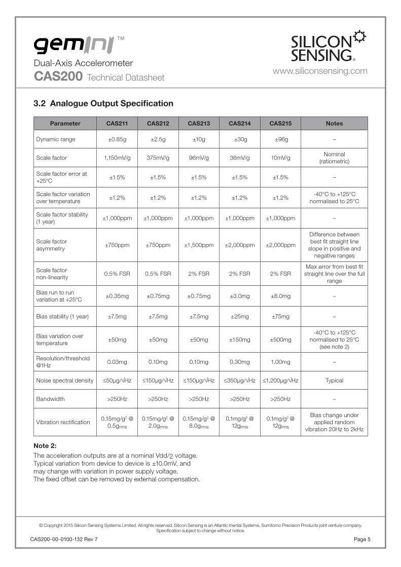
3.2 Analogue Output Specifi cation
Parameter CAS211 CAS212 CAS213 CAS214 CAS215 Notes
Dynamic range ±0.85g ±2.5g ±10g ±30g ±96g –
Scale factor 1,150mV/g 375mV/g 96mV/g 36mV/g 10mV/gNominal
(ratiometric)
Scale factor error at +25°C
±1.5% ±1.5% ±1.5% ±1.5% ±1.5% –
Scale factor variation over temperature
±1.2% ±1.2% ±1.2% ±1.2% ±1.2%-40°C to +125°C
normalised to 25°C
Scale factor stability(1 year)
±1,000ppm ±1,000ppm ±1,000ppm ±1,000ppm ±1,000ppm –
Scale factorasymmetry
±750ppm ±750ppm ±1,500ppm ±2,000ppm ±2,000ppm
Difference between best fi t straight line
slope in positive and negative ranges
Scale factornon-linearity
0.5% FSR 0.5% FSR 2% FSR 2% FSR 2% FSRMax error from best fi t straight line over the full
range
Bias run to runvariation at +25°C
±0.35mg ±0.75mg ±0.75mg ±3.0mg ±8.0mg –
Bias stability (1 year) ±7.5mg ±7.5mg ±7.5mg ±25mg ±75mg –
Bias variation over temperature
±50mg ±50mg ±50mg ±150mg ±500mg-40°C to +125°C
normalised to 25°C(see note 2)
Resolution/threshold @1Hz
0.03mg 0.10mg 0.10mg 0.30mg 1.00mg –
Noise spectral density 50μg/Hz 150μg/Hz 150μg/Hz 350μg/Hz 1,200μg/Hz Typical
Bandwidth >250Hz >250Hz >250Hz >250Hz >250Hz –
Vibration rectifi cation0.15mg/g2 @
0.5grms 0.15mg/g2 @
2.0grms 0.15mg/g2 @
8.0grms 0.1mg/g2 @
12grms
0.1mg/g2 @ 12grms
Bias change under applied random
vibration 20Hz to 2kHz
Note 2:
The acceleration outputs are at a nominal Vdd/2 voltage.Typical variation from device to device is ±10.0mV, andmay change with variation in power supply voltage.The fi xed offset can be removed by external compensation.
Page 5CAS200-00-0100-132 Rev 7
© Copyright 2015 Silicon Sensing Systems Limited. All rights reserved. Silicon Sensing is an Atlantic Inertial Systems, Sumitomo Precision Products joint venture company.Specifi cation subject to change without notice.
Dual-Axis Accelerometer
CAS200 Technical Datasheetwww.siliconsensing.com

CAS200-00-0100-132 Rev 7Page 6
© Copyright 2015 Silicon Sensing Systems Limited. All rights reserved. Silicon Sensing is an Atlantic Inertial Systems, Sumitomo Precision Products joint venture company.Specifi cation subject to change without notice.
Dual-Axis Accelerometer
CAS200 Technical Datasheet
Specifi cation Continued
CAS211, CAS212, CAS213, CAS214 & CAS215Parameter Minimum Typical Maximum Notes
Temperature Sensor (Digital Output):
Scale factor – 11lsb/°C – At +25°C
Offset – 2380lsb – At +25°C
Temperature Sensor (Analogue Output):
Scale factor – 5mV/°C – –
Offset – 1.49V – At +25°C
Repeatability -5°C – +5°C –
Start Up:
Start up time – – 20ms –
Recovery time – – 10ms From over range/shock
Physical:
Mass – 0.4grams – –
Misalignment -20mrad – 20mrad –
Orthogonality – 1.7mrad –Internal relative to the other
sensor
www.siliconsensing.com
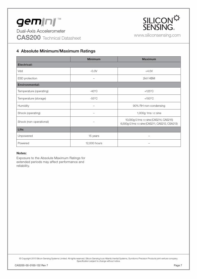
4 Absolute Minimum/Maximum Ratings
Minimum Maximum
Electrical:
Vdd -0.3V +4.0V
ESD protection – 2kV HBM
Environmental:
Temperature (operating) -40°C +125°C
Temperature (storage) -55°C +150°C
Humidity – 90% RH non-condensing
Shock (operating) – 1,000g 1ms 1/2 sine
Shock (non-operational) –10,000g 0.1ms 1/2 sine (CAS214, CAS215)
6,500g 0.1ms 1/2 sine (CAS211, CAS212, CSA213)
Life:
Unpowered 15 years –
Powered 12,000 hours –
Notes:
Exposure to the Absolute Maximum Ratings forextended periods may affect performance andreliability.
Page 7CAS200-00-0100-132 Rev 7
© Copyright 2015 Silicon Sensing Systems Limited. All rights reserved. Silicon Sensing is an Atlantic Inertial Systems, Sumitomo Precision Products joint venture company.Specifi cation subject to change without notice.
Dual-Axis Accelerometer
CAS200 Technical Datasheetwww.siliconsensing.com

CAS200-00-0100-132 Rev 7Page 8
© Copyright 2015 Silicon Sensing Systems Limited. All rights reserved. Silicon Sensing is an Atlantic Inertial Systems, Sumitomo Precision Products joint venture company.Specifi cation subject to change without notice.
Dual-Axis Accelerometer
CAS200 Technical Datasheet
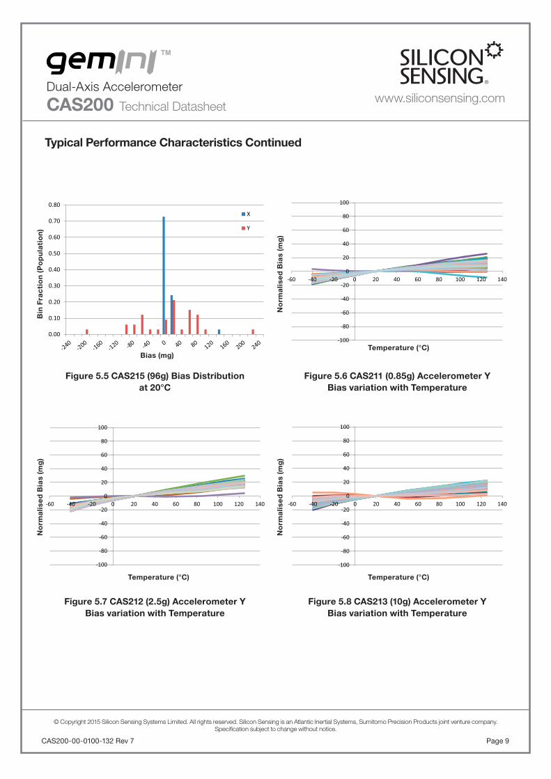
5 Typical Performance CharacteristicsGraphs showing typical performance characteristics for GeminiTM are shown below:Note: Typical data is with the device powered from a 3.3V supply.
www.siliconsensing.com
Figure 5.3 CAS213 (10g) Bias Distributionat 20°C
Figure 5.4 CAS214 (30g) Bias Distributionat 20°C
0
0.1
0.2
0.3
0.4
0.5
0.6X
Y
0.00
0.10
0.20
0.30
0.40
0.50
0.60X
Y
0.00
0.05
0.10
0.15
0.20
0.25X
Y
0.00
0.02
0.04
0.06
0.08
0.10
0.12
0.14
0.16
0.18X
Y
Figure 5.1 CAS211 (0.85g) Bias Distributionat 20°C
Figure 5.2 CAS212 (2.5g) Bias Distributionat 20°C
Bias (mg)
Bias (mg)
Bias (mg)
Bias (mg)
Bin
Fra
cti
on
(P
op
ula
tio
n)
Bin
Fra
cti
on
(P
op
ula
tio
n)
Bin
Fra
cti
on
(P
op
ula
tio
n)
Bin
Fra
cti
on
(P
op
ula
tio
n)
Page 9CAS200-00-0100-132 Rev 7
© Copyright 2015 Silicon Sensing Systems Limited. All rights reserved. Silicon Sensing is an Atlantic Inertial Systems, Sumitomo Precision Products joint venture company.Specifi cation subject to change without notice.
Dual-Axis Accelerometer
CAS200 Technical Datasheet
Typical Performance Characteristics Continued
www.siliconsensing.com
Figure 5.7 CAS212 (2.5g) Accelerometer YBias variation with Temperature
Figure 5.8 CAS213 (10g) Accelerometer YBias variation with Temperature
0.00
0.10
0.20
0.30
0.40
0.50
0.60
0.70
0.80X
Y
-100
-80
-60
-40
-20
0
20
40
60
80
100
-60 -40 -20 0 20 40 60 80 100 120 140
-100
-80
-60
-40
-20
0
20
40
60
80
100
-60 -40 -20 0 20 40 60 80 100 120 140
-100
-80
-60
-40
-20
0
20
40
60
80
100
-60 -40 -20 0 20 40 60 80 100 120 140
Figure 5.5 CAS215 (96g) Bias Distributionat 20°C
Figure 5.6 CAS211 (0.85g) Accelerometer YBias variation with Temperature
Bias (mg)Temperature (°C)
Temperature (°C)Temperature (°C)
Bin
Fra
cti
on
(P
op
ula
tio
n)
No
rma
lise
d B
ias
(mg
)N
orm
alis
ed
Bia
s (m
g)
No
rma
lise
d B
ias
(mg
)

CAS200-00-0100-132 Rev 7Page 10
© Copyright 2015 Silicon Sensing Systems Limited. All rights reserved. Silicon Sensing is an Atlantic Inertial Systems, Sumitomo Precision Products joint venture company.Specifi cation subject to change without notice.
Dual-Axis Accelerometer
CAS200 Technical Datasheet
Typical Performance Characteristics Continued
www.siliconsensing.com
Figure 5.11 CAS211 (0.85g) Accelerometer XBias variation with Temperature
Figure 5.12 CAS212 (2.5g) Accelerometer XBias variation with Temperature
-200
-160
-120
-80
-40
0
40
80
120
160
200
-60 -40 -20 0 20 40 60 80 100 120 140
-100
-80
-60
-40
-20
0
20
40
60
80
100
-60 -40 -20 0 20 40 60 80 100 120 140
-600
-400
-200
0
200
400
600
-60 -40 -20 0 20 40 60 80 100 120 140
-100
-80
-60
-40
-20
0
20
40
60
80
100
-60 -40 -20 0 20 40 60 80 100 120 140
Figure 5.9 CAS214 (30g) Accelerometer YBias variation with Temperature
Figure 5.10 CAS215 (96g) Accelerometer YBias variation with Temperature
Temperature (°C)
Temperature (°C)
Temperature (°C)
Temperature (°C)
No
rma
lise
d B
ias
(mg
)N
orm
alis
ed
Bia
s (m
g)
No
rma
lise
d B
ias
(mg
)N
orm
alis
ed
Bia
s (m
g)

Page 11CAS200-00-0100-132 Rev 7
© Copyright 2015 Silicon Sensing Systems Limited. All rights reserved. Silicon Sensing is an Atlantic Inertial Systems, Sumitomo Precision Products joint venture company.Specifi cation subject to change without notice.
Dual-Axis Accelerometer
CAS200 Technical Datasheet
Typical Performance Characteristics Continued
www.siliconsensing.com
-100
-80
-60
-40
-20
0
20
40
60
80
100
-60 -40 -20 0 20 40 60 80 100 120 140
-600
-400
-200
0
200
400
600
-60 -40 -20 0 20 40 60 80 100 120 140
-200
-160
-120
-80
-40
0
40
80
120
160
200
-60 -40 -20 0 20 40 60 80 100 120 140
-1.50
-1.00
-0.50
0.00
0.50
1.00
1.50
-60 -40 -20 0 20 40 60 80 100 120 140
Figure 5.13 CAS213 (10g) Accelerometer XBias variation with Temperature
Figure 5.15: CAS215(96g) Accelerometer XBias variation with Temperature
Figure 5.14: CAS214(30g) Accelerometer XBias variation with Temperature
Figure 5.16 CAS211 (0.85g) Accelerometer YSF Error with Temperature
Temperature (°C) Temperature (°C)
Temperature (°C) Temperature (°C)
No
rma
lise
d B
ias
(mg
)
No
rma
lise
d S
F E
rro
r (%
)
No
rma
lise
d B
ias
(mg
)
No
rma
lise
d B
ias
(mg
)

CAS200-00-0100-132 Rev 7Page 12
© Copyright 2015 Silicon Sensing Systems Limited. All rights reserved. Silicon Sensing is an Atlantic Inertial Systems, Sumitomo Precision Products joint venture company.Specifi cation subject to change without notice.
Dual-Axis Accelerometer
CAS200 Technical Datasheet
Typical Performance Characteristics Continued
www.siliconsensing.com
-1.50
-1.00
-0.50
0.00
0.50
1.00
1.50
-60 -40 -20 0 20 40 60 80 100 120 140
-1.50
-1.00
-0.50
0.00
0.50
1.00
1.50
-60 -40 -20 0 20 40 60 80 100 120 140
-1.50
-1.00
-0.50
0.00
0.50
1.00
1.50
-60 -40 -20 0 20 40 60 80 100 120 140
-1.50
-1.00
-0.50
0.00
0.50
1.00
1.50
-60 -40 -20 0 20 40 60 80 100 120 140
Figure 5.17 CAS212 (2.5g) Accelerometer YSF Error with Temperature
Figure 5.19 CAS214 (30g) Accelerometer YSF Error with Temperature
Figure 5.18 CAS213 (10g) Accelerometer YSF Error with Temperature
Figure 5.20 CAS215 (96g) Accelerometer YSF Error with Temperature
Temperature (°C)
Temperature (°C)
Temperature (°C)
Temperature (°C)
No
rma
lise
d S
F E
rro
r (%
)N
orm
alis
ed
SF
Err
or
(%)
No
rma
lise
d S
F E
rro
r (%
)N
orm
alis
ed
SF
Err
or
(%)

Page 13CAS200-00-0100-132 Rev 7
© Copyright 2015 Silicon Sensing Systems Limited. All rights reserved. Silicon Sensing is an Atlantic Inertial Systems, Sumitomo Precision Products joint venture company.Specifi cation subject to change without notice.
Dual-Axis Accelerometer
CAS200 Technical Datasheet
Typical Performance Characteristics Continued
www.siliconsensing.com
-1.50
-1.00
-0.50
0.00
0.50
1.00
1.50
-60 -40 -20 0 20 40 60 80 100 120 140
-1.50
-1.00
-0.50
0.00
0.50
1.00
1.50
-60 -40 -20 0 20 40 60 80 100 120 140
-1.50
-1.00
-0.50
0.00
0.50
1.00
1.50
-60 -40 -20 0 20 40 60 80 100 120 140
-1.50
-1.00
-0.50
0.00
0.50
1.00
1.50
-60 -40 -20 0 20 40 60 80 100 120 140
Figure 5.21 CAS211 (0.85g) Accelerometer XSF Error with Temperature
Figure 5.23 CAS213 (10g) Accelerometer XSF Error with Temperature
Figure 5.22 CAS212 (2.5g) Accelerometer XSF Error with Temperature
Figure 5.24 CAS214 (30g) Accelerometer XSF Error with Temperature
Temperature (°C) Temperature (°C)
Temperature (°C) Temperature (°C)
No
rma
lise
d S
F E
rro
r (%
)
No
rma
lise
d S
F E
rro
r (%
)
No
rma
lise
d S
F E
rro
r (%
)
No
rma
lise
d S
F E
rro
r (%
)
CAS200-00-0100-132 Rev 7Page 14
© Copyright 2015 Silicon Sensing Systems Limited. All rights reserved. Silicon Sensing is an Atlantic Inertial Systems, Sumitomo Precision Products joint venture company.Specifi cation subject to change without notice.
Dual-Axis Accelerometer
CAS200 Technical Datasheetwww.siliconsensing.com
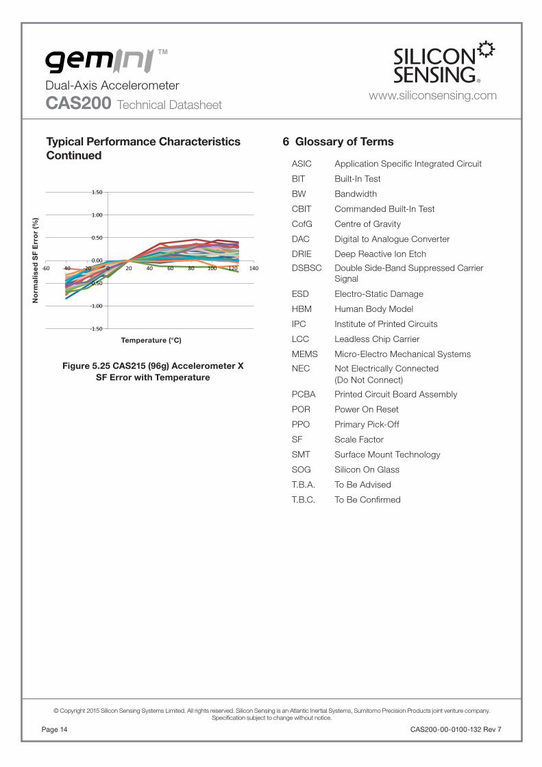
6 Glossary of Terms
ASIC Application Specifi c Integrated Circuit
BIT Built-In Test
BW Bandwidth
CBIT Commanded Built-In Test
CofG Centre of Gravity
DAC Digital to Analogue Converter
DRIE Deep Reactive Ion Etch
DSBSC Double Side-Band Suppressed Carrier Signal
ESD Electro-Static Damage
HBM Human Body Model
IPC Institute of Printed Circuits
LCC Leadless Chip Carrier
MEMS Micro-Electro Mechanical Systems
NEC Not Electrically Connected(Do Not Connect)
PCBA Printed Circuit Board Assembly
POR Power On Reset
PPO Primary Pick-Off
SF Scale Factor
SMT Surface Mount Technology
SOG Silicon On Glass
T.B.A. To Be Advised
T.B.C. To Be Confi rmed
Typical Performance CharacteristicsContinued
-1.50
-1.00
-0.50
0.00
0.50
1.00
1.50
-60 -40 -20 0 20 40 60 80 100 120 140
Figure 5.25 CAS215 (96g) Accelerometer XSF Error with Temperature
Temperature (°C)
No
rma
lise
d S
F E
rro
r (%
)

Page 15CAS200-00-0100-132 Rev 7
© Copyright 2015 Silicon Sensing Systems Limited. All rights reserved. Silicon Sensing is an Atlantic Inertial Systems, Sumitomo Precision Products joint venture company.Specifi cation subject to change without notice.
Dual-Axis Accelerometer
CAS200 Technical Datasheet
7 InterfacePhysical and electrical inter-connect information.
7.1 Physical and Electrical Interface, Pad Layout and Pinouts
Figure 7.2 Recommended Pad Layout
6.55
3.65
2.55 x 6.1 0.6 x 2.4 1.2 x 5.0
2.15
2.15
4.2
1 2 3 4 5 6
12 1413
15
11 10 9 8 7
0.9
4.2
C.G. 18541Note:
Figure 7.1 Pinout (Top View)
C.G.18581
1 2 3 4
15Pad
13Pad
14Pad
NECNEC
5 6
12 11 10 9 8 7
Vss
Vdd
Dcl
k
Dat
a_O
ut
SS
Acc
X A
NA
Dat
a_In
PR
OG
AC
C_V
dd_C
ap
Tem
p_O
ut
Acc
Y A
NA
Vre
f_C
ap
NOTE: Pins 13, 14, & 15 are for mechanical fixing purposes and should be soldered to an unconnected pad (NEC).
Vss
Vdd (2.7 to 3.6V)
Vdd
NEC
NE
C
NE
C
NE
C
SS
Dat
a_O
ut
Dcl
k
Dat
a_In
NEC
12 117
15
NEC 14 13
Acc
X A
NA
9
PR
OG
AC
C_V
dd_C
ap
Tem
p_O
ut
Acc
Y A
NA
Vre
f_C
ap
10
CAS200 Series
8 2
1 6 4 3 5
C2 100nF
C1 10µF
C3 100nF
C4 100nF
C.G. 18578
Vss
Vdd (2.7V to 3.6V)
Dcl
k
Vdd
Dat
a_O
ut
NEC
NEC
SS
Acc
X A
NA
Dat
a_In
M
OS
I
MIS
O
Sla
ve S
elec
t
SP
I Clo
ck O
ut
11 127
15
NEC 14 13
9
PR
OG
AC
C_V
dd_C
ap
Tim
e_O
ut
Vre
f_C
ap
10
HOST SYSTEM
CAS200 Series
8 2
1 6 3 5
C2 100nF
C1 10µF
C3 100nF
C4 100nF
C G 18639
Acc
Y A
NA
4
Figure 7.3 Analogue Output Setup
Figure 7.4 Digital Output Setup
All dimensions in millimetres.
www.siliconsensing.com
Note: The Gemini accelerometers are capacitive sensors.The routing of signal tracks beneath the package (including power supply signals connecting to starpoints) can cause an offset in accelerometer bias. If such routing is unavoidable, the resulting offset can be removed by compensation at the higher system level.

CAS200-00-0100-132 Rev 7Page 16
© Copyright 2015 Silicon Sensing Systems Limited. All rights reserved. Silicon Sensing is an Atlantic Inertial Systems, Sumitomo Precision Products joint venture company.Specifi cation subject to change without notice.
Dual-Axis Accelerometer
CAS200 Technical Datasheetwww.siliconsensing.com
Table 7.2 Electrical Characteristics
Parameter Minimum Maximum Units
Supply
Supply voltage (functional) 2.7 3.6 V
Supply voltage (full specifi cation) 3.15 3.45 V
Supply voltage limits -0.3 4.0 V
Supply current – 5 mA
Discretes
Input voltage low -0.5 0.3xVdd V
Input voltage high 0.7xVdd Vdd+0.5 V
Output voltage low – 0.4 V
Output voltage high 0.8xVdd – V
Analogue
Output impedance – <1k
Output load capacitance – 300 pF
Input impedance 50k –
Output source/sink current – 1 mA
Table 7.1 Input/Output Pin Defi nitions
Pin Number Pin NameSignal
DirectionPin Function
1 Vdd_Cap –Used to smooth supply to CAS200.
A 100nF X7R dielectric ceramic capacitor is recommended.
2 PROG Input For factory use, must be connected to Vdd in operation
3 Temp_Out OutputAnalogue temperature output. Scaling 5mV/°C at 3.3V supply
- Ambient temperature reading of 1.474V
4 Acc Y ANA Output Y Accelerometer analogue output
5 Vss – Return connection for applied power (0V)
6 Vref_Cap –Used to decouple the internal voltage reference via an external capacitor. A
100nF X7R dielectric ceramic capacitor is recommended.
7 Data_Out OutputDigital mode: SPI_MISO. Only enabled when SPI_Select is low. Tri-stated
when SPI_SELECT is high.
8 Dclk Input Digital mode: SPI_CLK Internal Pull-up
9 Data_In Input Digital mode: SPI_MOSI Internal Pull-up
10 SS Input Digital mode: SPI_SELECT Internal Pull-up
11 Acc X ANA Input X Accelerometer analogue output
12 Vdd –Positive power supply to the sensor. Range from 2.7 to 3.6V. Should be
decoupled with a 100nF X7R dielectric ceramic capacitor,a bulk storage capacitor of 10μF should be nearby.
Centre and Side Pads (13,14 & 15)
NEC –Not Electrically Connected. These pins provide additional
mechanical fi xing to the Host System and should besoldered to an unconnected pad.
Page 17CAS200-00-0100-132 Rev 7
© Copyright 2015 Silicon Sensing Systems Limited. All rights reserved. Silicon Sensing is an Atlantic Inertial Systems, Sumitomo Precision Products joint venture company.Specifi cation subject to change without notice.
Dual-Axis Accelerometer
CAS200 Technical Datasheet
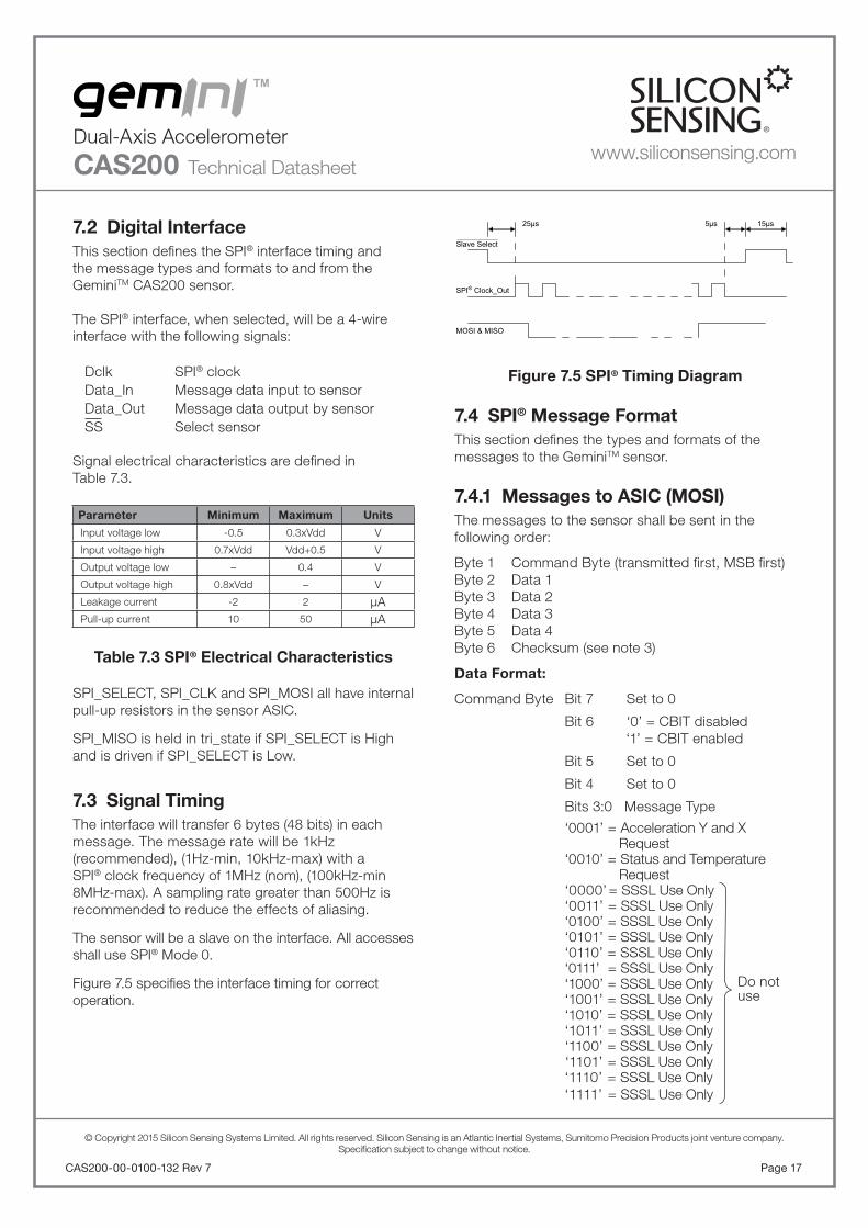
7.2 Digital InterfaceThis section defi nes the SPI® interface timing andthe message types and formats to and from theGeminiTM CAS200 sensor.
The SPI® interface, when selected, will be a 4-wireinterface with the following signals:
Dclk SPI® clockData_In Message data input to sensorData_Out Message data output by sensorSS Select sensor
Signal electrical characteristics are defi ned inTable 7.3.
Parameter Minimum Maximum Units
Input voltage low -0.5 0.3xVdd V
Input voltage high 0.7xVdd Vdd+0.5 V
Output voltage low – 0.4 V
Output voltage high 0.8xVdd – V
Leakage current -2 2 μAPull-up current 10 50 μA
Table 7.3 SPI® Electrical Characteristics
SPI_SELECT, SPI_CLK and SPI_MOSI all have internal pull-up resistors in the sensor ASIC.
SPI_MISO is held in tri_state if SPI_SELECT is High and is driven if SPI_SELECT is Low.
7.3 Signal TimingThe interface will transfer 6 bytes (48 bits) in eachmessage. The message rate will be 1kHz (recommended), (1Hz-min, 10kHz-max) with a SPI® clock frequency of 1MHz (nom), (100kHz-min 8MHz-max). A sampling rate greater than 500Hz is recommended to reduce the effects of aliasing.
The sensor will be a slave on the interface. All accesses shall use SPI® Mode 0.
Figure 7.5 specifi es the interface timing for correct operation.
Figure 7.5 SPI® Timing Diagram
7.4 SPI® Message FormatThis section defi nes the types and formats of the messages to the GeminiTM sensor.
7.4.1 Messages to ASIC (MOSI)The messages to the sensor shall be sent in the following order:
Byte 1 Command Byte (transmitted fi rst, MSB fi rst)Byte 2 Data 1Byte 3 Data 2Byte 4 Data 3Byte 5 Data 4Byte 6 Checksum (see note 3)
Data Format:
Command Byte Bit 7 Set to 0
Bit 6 ‘0’ = CBIT disabled ‘1’ = CBIT enabled
Bit 5 Set to 0
Bit 4
Set to 0
Bits 3:0 Message Type
‘0001’ = Acceleration Y and X Request ‘0010’ = Status and Temperature Request ‘0000’ = SSSL Use Only ‘0011’ = SSSL Use Only ‘0100’ = SSSL Use Only ‘0101’ = SSSL Use Only ‘0110’ = SSSL Use Only ‘0111’ = SSSL Use Only ‘1000’ = SSSL Use Only ‘1001’ = SSSL Use Only ‘1010’ = SSSL Use Only ‘1011’ = SSSL Use Only ‘1100’ = SSSL Use Only ‘1101’ = SSSL Use Only ‘1110’ = SSSL Use Only ‘1111’ = SSSL Use Only
Slave Select
SPI® Clock_Out
MOSI & MISO
5μs25μs 15μs
Do notuse
www.siliconsensing.com

CAS200-00-0100-132 Rev 7Page 18
© Copyright 2015 Silicon Sensing Systems Limited. All rights reserved. Silicon Sensing is an Atlantic Inertial Systems, Sumitomo Precision Products joint venture company.Specifi cation subject to change without notice.
Dual-Axis Accelerometer
CAS200 Technical Datasheetwww.siliconsensing.com
Message Data:
The following table defi nes the content of each byteof the input message.
Message Type Data Byte Byte Content
Acc Y/Acc XorStatus/Temp
1 Bits (7.0) set to 0x00
2 Bits (7.0) set to 0x00
3 Bits (7.0) set to 0x00
4 Bits (7.0) set to 0x00
Table 7.4 Message Content to GeminiTM
Example message data:
1. To request Acc Y and Acc X data only.
Command Byte = 0x01Data 1 Byte = 0x00Data 2 Byte = 0x00Data 3 Byte = 0x00Data 4 Byte = 0x00Checksum = 0xFE
2. To request Status and Temperature.
Command Byte = 0x02Data 1 Byte = 0x00Data 2 Byte = 0x00Data 3 Byte = 0x00Data 4 Byte = 0x00Checksum = 0xFD
3. To request CBIT and Acc Y and Acc X data.
Command Byte = 0x41Data 1 Byte = 0x00Data 2 Byte = 0x00Data 3 Byte = 0x00Data 4 Byte = 0x00Checksum = 0xBE
4. To request CBIT and Status and Temperature.
Command Byte = 0x42Data 1 Byte = 0x00Data 2 Byte = 0x00Data 3 Byte = 0x00Data 4 Byte = 0x00Checksum = 0xBD
7.4.2 Message from GeminiTM (MISO)The messages from the sensor shall be sent in the following order.
Byte 1: Status Byte (MSB transmitted fi rst)Byte 2: Data 1Byte 3: Data 2Byte 4: Data 3Byte 5: Data 4Byte 6: Checksum (see notes 3 and 4)
The data is output in 2’s complement format, most signifi cant byte fi rst.
Data Format:
The Status Byte content depends on the message requested.
Status Byte Bit 7 Sensor BIT Status‘1’ = BIT Failed‘0’ = Sensor OK
Bit 6 ACC 1 BIT Status‘1’ = Acc Y Failed‘0’ = Acc Y OK
Bit 5 ACC 2 BIT Status‘1’ = Acc X Failed‘0’ = Acc X OK
Bit 4 ‘1’ = Previous Input ChecksumBIT Failed
‘0’ = Previous Input ChecksumBIT OK
Bit 3 ‘0’ = CBIT disabled ‘1’ = CBIT enabled
Bit 2:0 Output Message Type ‘001’ = Acc Y/ Acc X ‘010’ = Status Message/
Temperature Message‘000’‘011’‘100’‘101’‘110’‘111’
Not used

Page 19CAS200-00-0100-132 Rev 7
© Copyright 2015 Silicon Sensing Systems Limited. All rights reserved. Silicon Sensing is an Atlantic Inertial Systems, Sumitomo Precision Products joint venture company.Specifi cation subject to change without notice.
Dual-Axis Accelerometer
CAS200 Technical Datasheet
5. For the status byte the following conditions apply.
Acc_bit _Status (0) = Acc Y ‘0’ = Pass, ‘1’ = FailAcc_bit _Status (1) = Acc X ‘0’ = Pass, ‘1’ = FailVref_cap_bit ‘0’ = Pass, ‘1’ = FailAcc_cap_bit ‘0’ = Pass, ‘1’ = FailCBit_en ‘0’ = CBIT OFF, ‘1’ = CBIT ON
7.5 CBITThe GeminiTM sensor has a Commanded Built in Test (CBIT) function which stimulates the output to give a synthetic acceleration output. This allows the acceleration channel to be functionally tested, identifying potential failure. CBIT can be requested using the Command Byte as detailed in Section 7.4.1. The sensor will respond by applying a fi xed offset to both acceleration outputs.The offset applied depends on the CAS variant being used, see Table 7.6 for details. The offset added will have a ±20% tolerance due to MEMS tolerance effects. The time taken to apply these offsets will be less than 35ms.
The intrusive nature of CBIT is such that whilst thesensor may continue to be used to indicate acceleration, the performance is not guaranteed while CBIT is asserted.
For full performance acceleration measurement, it is recommended that 35ms is allowed to elapse following the de-assertion of CBIT to allow the sensor to settle again.
Parameter CAS200 Variant Offset Added
Acceleration(both axes)
CAS215 (96g) 36.5g
CAS214 (30g) 10g
CAS213 (10g) 3.75g
CAS212 (2.5g) 0.92g
CAS211 (0.85g) 0.23g
Table 7.6 CBIT Offset for CAS200 Sensor
Message Data Content:
The output message data content will depend on the command byte from the previous input message.The content is indicated by bits (2:0) of the Status byte.
Message Type Data Byte Byte Content
Acc Y/Acc X
1 Bits (7.0) - Acc Y MS bits (15:8)
2 Bits (7.0) - Acc Y LS bits (7:0)
3 Bits (7.0) - Acc X MS bits (15:8)
4 Bits (7.0) - Acc X LS bits (7:0)
Status/Temp
1
Status Byte 1 (see note 5)
Bit (7:6) - acc_bit_statusBit 5 - vref_cap_bitBit 4 - acc_cap_bitBit 3 - cbit_enBit 2 ‘0’ = OTP Parity OK ‘1’ = OTP Parity FailBit 1 ‘0’ = Previous input checksum Message Checksum OK ‘1’ = Previous input checksum Message Checksum Fail Bit 0 ‘1’
2 Bits (7.0) - (set to ‘0x00’)
3 Bits (7.0) - Temperature MS bits (15:8)
4 Bits (7.0) - Temperature LS bits (7:0)
Table 7.5 Message Content from ASIC
Notes:
3. The checksum is the LS byte of the 1’s complement of the fi rst 5 bytes of message. If the checksum is incorrect the input message will be ignored and the checksum error fl agged in the status byte of the next SPI® message. The content of the message following a bad checksum message shall be the message type selected in the last ‘good’ message. The message type shall default on power-up to Acc Y/Acc X message.
4. The checksum for the output message is calculated before the message is loaded into the SPI® registers. When the checksum is about to be calculated, the Data Bytes are stored and updates to them are inhibited. The Checksum is then calculated on the Status Byte and these 4 Data Bytes. The Status Byte can continue to be updated for a short time after the Checksum has been calculated. Therefore when the Status Byte, 4 Data Bytes and the Checksum are loaded into the SPI® register there is a small chance that the Checksum will be incorrect. It is therefore advised that if a Checksum Error is detected that the Status Byte should still be interrogated for the Status, such as BIT Fault.
www.siliconsensing.com

CAS200-00-0100-132 Rev 7Page 20
© Copyright 2015 Silicon Sensing Systems Limited. All rights reserved. Silicon Sensing is an Atlantic Inertial Systems, Sumitomo Precision Products joint venture company.Specifi cation subject to change without notice.
Dual-Axis Accelerometer
CAS200 Technical Datasheetwww.siliconsensing.com
8 Design Tools and Resources AvailableThe following is planned to be available from the websitein the near future.
Item Description of Resource Part Number Order/Download
GeminiTM Brochure: A one page sales brochure describing the key features of the GeminiTM Accelerometers.
CAS200-00-0100-131Download
(www.siliconsensing.com)
GeminiTM CAS200 Datasheet: Full technical information on all part number options. Specifi cation and other essential information for assembling and interfacing toGeminiTM Accelerometers, and getting the most out of them.
CAS200-00-0100-132Download
(www.siliconsensing.com)
GeminiTM CAS290 Datasheet: Full technical information on all part number options. Specifi cation and other essential information for assembling and interfacing toGeminiTM Accelerometers, and getting the most out of them.
CAS290-00-0100-132Download
(www.siliconsensing.com)
GeminiTM Presentation: A useful presentation describing the features, construction, principles of operation and applications for the GeminiTM Accelerometers.
—Download
(www.siliconsensing.com)
GeminiTM evaluation board: Single GeminiTM fi tted to a small PCBA for easy customer evaluation and test purposes. Refer to page 3 for ordering information.
CAS211-0302CAS212-0302CAS213-0302CAS214-0302CAS215-0302
Order
CAS291-0302CAS292-0302CAS293-0302CAS294-0302CAS295-0302
Order
Solid Model CAD fi les for GeminiTM Accelerometers:Available in .STP and .IGS fi le format
CAS200-00-0100-408
Download(www.siliconsensing.com)
CAS290-00-0100-408
Library Parts:Useful library component fi les of GeminiTM Accelerometers:DxDesigner Schematic Symbols.PADS Decal (Footprint)PADS Part Type File.
—Download
(www.siliconsensing.com)
Reference Circuit: A useful reference circuit design gerber fi les for the GeminiTM Accelerometer for use in host systems.
—Download
(www.siliconsensing.com)
Questions and Answers: Some useful questions asked by customers and how we’ve answered them. This is an informal (uncontrolled) document intended purely as additional information.
—Download
(www.siliconsensing.com)
RoHS compliance statement for GeminiTM : GeminiTM is fully compliant with RoHS.
—Download
(www.siliconsensing.com)

Page 21CAS200-00-0100-132 Rev 7
© Copyright 2015 Silicon Sensing Systems Limited. All rights reserved. Silicon Sensing is an Atlantic Inertial Systems, Sumitomo Precision Products joint venture company.Specifi cation subject to change without notice.
Dual-Axis Accelerometer
CAS200 Technical Datasheet
9 CleaningDue to the natural resonant frequency and amplifi cation factor (‘Q’) of the sensor, ultrasonic cleaning should NOT be used to clean the GeminiTM Accelerometer.
10 Soldering Information
Figure 10.1 Recommended Refl owSolder Profi le
11 Part Markings
Figure 11.1 Part Marking
CAS213-CYYMMLLLXXXMade In Japan
Silicon Sensing Company Logo
Hardware Configuration(See Table 11.1)
Serial Number(See Table 11.1)
Country of Origin of Final Assembly and Test
Indicates Location of Pin 1
Part Number
2D Data Matrix Code Containing the Production Number
C.G. 18582
217°C
260°C
Time (sec)
Temp (°C)
255°C
Max 40sec
Max 120sec
200°C
150°C
Max 180sec
C.G. 18384
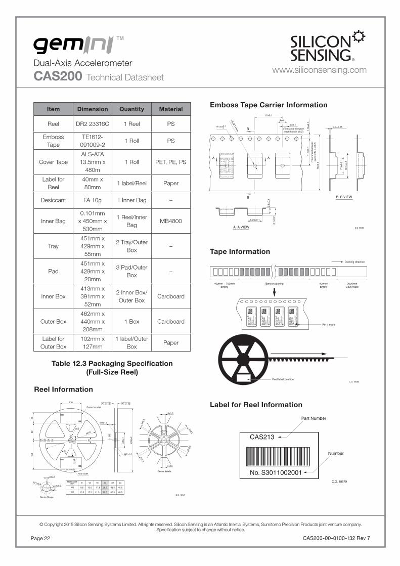
12 Packaging InformationGeminiTM sensors are supplied in tape format as either straight strips, or on either full-size or mini-reels, depending on the quantity being shipped. Table 12.1 defi nes the packaging method:
Shipping Quantity GeminiTM
Qty < 100 Strip of tape
100 Qty 1,000Tape and mini-reel(approx. Ø175mm)
Qty > 1,000Tape and full-size reel
(approx. Ø330mm)
Table 12.1 Packaging Tape and Reel Format According to Shipping Quantity
The following information in this section defi nes the packaging for shipments using full-size reels.
Layer Type Quantity
CAS200 Tape and ReelMax. 1500 pcs/
1 Reel
Inner BagAluminium
Damp-proof Bag1 Reel/Bag
Inner Box Cardboard BoxInner Bag x 1/Inner
Box
Outer Box Cardboard BoxInner Box/Outer
Box
Table 12.2 Packaging Information(Full-Size Reel)
Item Code Range
Confi guration C 1 - Z
Year number YY 00 - 99
Month number MM 01 - 12
Lot number LLL 000 - 999
Serial number XXX 001 - 999
Table 11.1 Part Marking (Serial Number)
www.siliconsensing.com
CAS200-00-0100-132 Rev 7Page 22
© Copyright 2015 Silicon Sensing Systems Limited. All rights reserved. Silicon Sensing is an Atlantic Inertial Systems, Sumitomo Precision Products joint venture company.Specifi cation subject to change without notice.
Dual-Axis Accelerometer
CAS200 Technical Datasheetwww.siliconsensing.com
Item Dimension Quantity Material
Reel DR2 23316C 1 Reel PS
Emboss Tape
TE1612-091009-2
1 Roll PS
Cover TapeALS-ATA 13.5mm x
480m1 Roll PET, PE, PS
Label for Reel
40mm x 80mm
1 label/Reel Paper
Desiccant FA 10g 1 Inner Bag –
Inner Bag0.101mm
x 450mm x 530mm
1 Reel/Inner Bag
MB4800
Tray451mm x 429mm x
55mm
2 Tray/Outer Box
–
Pad451mm x 429mm x
20mm
3 Pad/Outer Box
–
Inner Box413mm x 391mm x
52mm
2 Inner Box/Outer Box
Cardboard
Outer Box462mm x 440mm x 208mm
1 Box Cardboard
Label for Outer Box
102mm x 127mm
1 label/Outer Box
Paper
Table 12.3 Packaging Specifi cation(Full-Size Reel)
Emboss Tape Carrier Information
Tape Information
Label for Reel Information
Reel Information
110
10
W1±1.0
B
W2±1.0
3
30
30
0.2
0.4
0.6
0.8
5589
152
2±0.5
22
270
80±
1
330±
2
3±0.
5
5±0.
5
5±0.5
9±0.5
7±0.5
172
21±0.813±0.2
Frame for label
Reel width
Reel widthmm
Centre Shape
Centre detailsEIAJ.RRM.24.D
R1W1
W2
9.5
8
13.5
13.5
12
17.5
17.5
16
21.5
25.5
24
29.5
33.5
32
37.5
45.5
44
49.5
B 3 B
3±0.5
C.G. 18547
16±
0.3
2.6±
0.1
3.1±
0.2
6.25±0.1
0.3±0.05
7.3±
0.2
10.7
±0.
1
11.5
±0.
11.
75±
0.1
12±0.1
4±0.1
2±0.1
(Tolerance betweeneach hole is ±0.2)
(Tol
eran
ce b
etw
een
each
hol
e is
±0.
2)
1.5±0.1 Hole
1.5+0.1 0
A A
B
B B B VIEW
A A VIEW C.G.18546
400mm ~ 700mm Empty
400mm Empty
2000mm Cover tape
C.G. 18583
Pin 1 mark
Reel label position
Sensor packing
Drawing direction
CA
S21
3P
PY
YM
MLL
LLR
DD
Mad
e In
Jap
an
YY
MM
LLLL
_XX
XX
CA
S21
3P
PY
YM
MLL
LLR
DD
Mad
e In
Jap
an
YY
MM
LLLL
_XX
XX
CA
S21
3P
PY
YM
MLL
LLR
DD
Mad
e In
Jap
an
YY
MM
LLLL
_XX
XX
CA
S21
3P
PY
YM
MLL
LLR
DD
Mad
e In
Jap
an
YY
MM
LLLL
_XX
XX
CAS213
No. S3011002001
Part Number
Number
C.G. 18579

Page 23CAS200-00-0100-132 Rev 7
© Copyright 2015 Silicon Sensing Systems Limited. All rights reserved. Silicon Sensing is an Atlantic Inertial Systems, Sumitomo Precision Products joint venture company.Specifi cation subject to change without notice.
Dual-Axis Accelerometer
CAS200 Technical Datasheet
Outer Box Packing Information
C.G. 18390
2
1 Maximum of two Reels per Outer Box.If 1 Reel is contained in Outer Box, label ispasted in position 1.If 2 Reels are contained in Outer Box, labelsare pasted in positions 1 and 2.Each label shows packaged reel information.
Box
Craft Tape
Pad
Tray
Inner Box
Pad
Tray
Inner Box
Pad
Inner Bag Packing Information
Inner Box Packing Information
C.G. 18392
Desiccant
Inner Bag
Reel
C.G. 18389
Inner Bag Inner Box
www.siliconsensing.com
CAS200-00-0100-132 Rev 7Page 24
© Copyright 2015 Silicon Sensing Systems Limited. All rights reserved. Silicon Sensing is an Atlantic Inertial Systems, Sumitomo Precision Products joint venture company.Specifi cation subject to change without notice.
Dual-Axis Accelerometer
CAS200 Technical Datasheetwww.siliconsensing.com
13 Internal Construction and Theoryof Operation
Construction
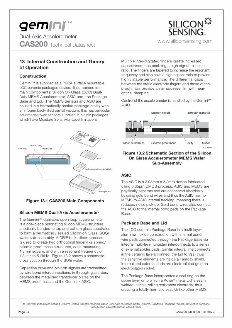
Gemini™ is supplied as a PCBA surface mountable LCC ceramic packaged device. It comprises four main components; Silicon On Glass (SOG) Dual-Axis MEMS Accelerometer, ASIC and, the Package Base and Lid. The MEMS Sensors and ASIC are housed in a hermetically sealed package cavity with a nitrogen back-fi lled partial vacuum, this has particular advantages over sensors supplied in plastic packages which have Moisture Sensitivity Level limitations.
Figure 13.1 CAS200 Main Components
Silicon MEMS Dual-Axis Accelerometer
The GeminiTM dual-axis open loop accelerometer is a one-piece resonating silicon MEMS structure anodically bonded to top and bottom glass substrates to form a hermetically sealed Silicon on Glass (SOG) wafer sub-assembly. A DRIE bulk silicon process is used to create two orthogonal fi nger-like spring/seismic proof mass structures, each measuring 1.8mm square, and with a resonant frequency of 1.8kHz to 5.2kHz. Figure 13.2 shows a schematic cross section through the SOG wafer.
Capacitive drive and pick-off signals are transmitted by wire bond interconnections, in through-glass vias, between the metallised transducer plates on the MEMS proof mass and the GeminiTM ASIC.
Cavity SiliconSeismic proof massGlass Substrates
Through-glass viaSupport flexure
C.G. 18538
Lid
Dual-Axis Accelerometer MEMS
ASIC
Package Base
Bond Wires
Vacuum Cavity
Seal Ring
CAS213-CYYMMLLLXXXMade In Japan
Multiple inter-digitated fi ngers create increased capacitance thus enabling a high signal-to-noise ratio. The fi ngers are tapered to increase the resonant frequency and also have a high aspect ratio to provide highly stable performance. The differential gaps between the static electrode fi ngers and those of the proof mass provide an air squeeze fi lm with near-critical damping.
Control of the accelerometer is handled by the GeminiTM ASIC.
Figure 13.2 Schematic Section of the Silicon On Glass Accelerometer MEMS Wafer
Sub-Assembly
ASIC
The ASIC is a 3.93mm x 3.2mm device fabricated using 0.35μm CMOS process. ASIC and MEMS are physically separate and are connected electrically by using gold bond wires and thus the ASIC has no MEMS-to-ASIC internal tracking, meaning there is reduced noise pick-up. Gold bond wires also connect the ASIC to the internal bond pads on the Package Base.
Package Base and Lid
The LCC ceramic Package Base is a multi-layer aluminium oxide construction with internal bond wire pads connected through the Package Base via integral multi-level tungsten interconnects to a series of external solder pads. Similar integral interconnects in the ceramic layers connect the Lid to Vss, thus the sensitive elements are inside a Faraday shield. Internal and external pads are electroplated gold on electroplated nickel.
The Package Base incorporates a seal ring on the upper layer onto which a Kovar® metal Lid is seam welded using a rolling resistance electrode, thus creating a totally hermetic seal. Unlike other MEMS
Page 25CAS200-00-0100-132 Rev 7
© Copyright 2015 Silicon Sensing Systems Limited. All rights reserved. Silicon Sensing is an Atlantic Inertial Systems, Sumitomo Precision Products joint venture company.Specifi cation subject to change without notice.
Dual-Axis Accelerometer
CAS200 Technical Datasheet
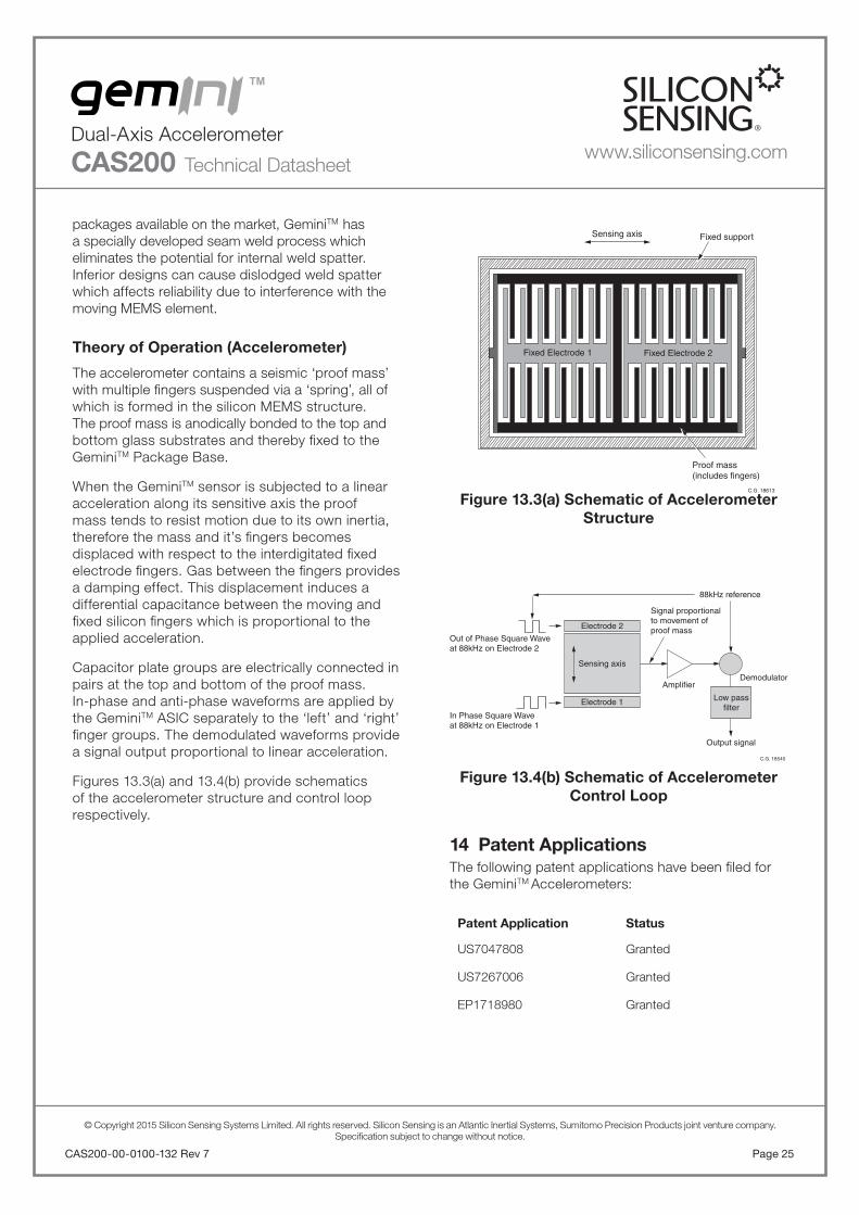
Figure 13.3(a) Schematic of Accelerometer Structure
Figure 13.4(b) Schematic of Accelerometer Control Loop
14 Patent ApplicationsThe following patent applications have been fi led for the GeminiTM Accelerometers:
Patent Application Status
US7047808 Granted
US7267006 Granted
EP1718980 Granted
C.G. 18540
Electrode 2
88kHz reference
Signal proportional to movement of proof mass
Out of Phase Square Wave at 88kHz on Electrode 2
In Phase Square Wave at 88kHz on Electrode 1
Amplifier
Electrode 1
Sensing axis
Low pass filter
Output signal
Demodulator
Fixed Electrode 1 Fixed Electrode 2
C.G. 18613
Sensing axis Fixed support
Proof mass(includes fingers)
packages available on the market, GeminiTM has a specially developed seam weld process which eliminates the potential for internal weld spatter.Inferior designs can cause dislodged weld spatter which affects reliability due to interference with the moving MEMS element.
Theory of Operation (Accelerometer)
The accelerometer contains a seismic ‘proof mass’ with multiple fi ngers suspended via a ‘spring’, all of which is formed in the silicon MEMS structure. The proof mass is anodically bonded to the top and bottom glass substrates and thereby fi xed to the GeminiTM Package Base.
When the GeminiTM sensor is subjected to a linear acceleration along its sensitive axis the proof mass tends to resist motion due to its own inertia, therefore the mass and it’s fi ngers becomes displaced with respect to the interdigitated fi xed electrode fi ngers. Gas between the fi ngers provides a damping effect. This displacement induces a differential capacitance between the moving and fi xed silicon fi ngers which is proportional to the applied acceleration.
Capacitor plate groups are electrically connected in pairs at the top and bottom of the proof mass. In-phase and anti-phase waveforms are applied by the GeminiTM ASIC separately to the ‘left’ and ‘right’ fi nger groups. The demodulated waveforms provide a signal output proportional to linear acceleration.
Figures 13.3(a) and 13.4(b) provide schematics of the accelerometer structure and control loop respectively.
www.siliconsensing.com

Specifi cation subject to change without notice.
© Copyright 2015Silicon Sensing Systems LimitedAll rights reserved.Printed in England 02/2015Date 06/02/2015
CAS200-00-0100-132 Rev 7DCR No. 710008482
Silicon Sensing Systems LimitedClittaford Road SouthwayPlymouth DevonPL6 6DE United Kingdom
T: +44 (0)1752 723330F: +44 (0)1752 723331W: siliconsensing.com
Silicon Sensing Systems Japan Limited1-10 Fuso-ChoAmagasakiHyogo 6600891 Japan
T: +81 (0)6 6489 5868F: +81 (0)6 6489 5919W: siliconsensing.com
CAS200-00-0100-132 Rev 7Page 26
© Copyright 2015 Silicon Sensing Systems Limited. All rights reserved. Silicon Sensing is an Atlantic Inertial Systems, Sumitomo Precision Products joint venture company.Specifi cation subject to change without notice.
Notes
Dual-Axis Accelerometer
CAS200 Technical Datasheetwww.siliconsensing.com