ds1 manual v1 - weiss engineering ltd. · florastrasse 42, 8610 uster, ... standard midi continuous...
TRANSCRIPT

digital audioweiss engineering ltd.Florastrasse 42, 8610 Uster, Switzerland) +41 1 940 20 06 2 +41 1 940 22 148 http://www.weiss.ch / http://www.weiss-highend.com
GAMBITDS1
OPERATING MANUAL
Software Version: 0S: 1.1
DSP: 1.0

OPERATING INSTRUCTIONS FOR GAMBIT DE-ESSER/COMPRESSOR DS1 FRONT PANEL
- Daniel Weiss Engineering Ltd., Florastr. 42, CH-8610 Uster Page 2 of 21) +41 1 940 20 06 2 +41 1 940 22 14 8 http://www.weiss.ch * [email protected]
FRONT PANEL
Graphic 1: Front Panel Elements
Graphic 2: Display Elements

OPERATING INSTRUCTIONS FOR GAMBIT DE-ESSER/COMPRESSOR DS1 FRONT PANEL
- Daniel Weiss Engineering Ltd., Florastr. 42, CH-8610 Uster Page 3 of 25) +41 1 940 20 06 2 +41 1 940 22 14 8 http://www.weiss.ch * [email protected]
Front Panel Groups
The front panel of the DS1 offers several control and display features.
Control
Refer to Graphic 1: Front Panel Elements
Ê - Menu- and softkeys p. 5
Ë - Snapshot keys p. 11
Ì - Preset keys p. 11
Í - Gain / Data knob p. 6
Î - Crossover knobs p. 10
Ï - Envelope detection knobs p. 8
Ð+Ñ - Non-linear transfer curve knobs p. 9
Display
Refer to Graphic 2: Display Elements
¬ - Gain value p. 6
- Crossover setting p. 10
® - Status display p. 5
¯ - Gain reduction meter p. 9
° - Envelope detection settings p. 8
± - Non-linear transfer curve and signal metering p. 9

OPERATING INSTRUCTIONS FOR GAMBIT DE-ESSER/COMPRESSOR DS1 INTRODUCTION
- Daniel Weiss Engineering Ltd., Florastr. 42, CH-8610 Uster Page 4 of 25) +41 1 940 20 06 2 +41 1 940 22 14 8 http://www.weiss.ch * [email protected]
INTRODUCTION
Congratulations on purchasing the Weiss Gambit Series DS1 De-esser / Compressor !
This two channel digital De-esser/Compressorfeatures linear-phase crossover filters coveringthe whole audio band. Thus the DS1 is not just aDe-esser but can also be used as band selectiveor full band Compressor / Limiter. The controlsfor the two channels are always ganged and thesidechains are always linked.
Specialities of the De-esser mode are absolutetransparency if no gain reduction is applied, fullyadjustable transfer curve and timing section andfour-times upsampling for high frequency tran-sient detection and a selectable working band.
In Compressor mode, the DS1 uses double-sampling signal processing for the whole com-pressor section (not only transient detection)yielding extremely reliable limiting functions andlow signal modulation distortion even for fasttiming settings. Valuable parameters like soft-kneeand auto gain makeup facilitate reaching exactlythe sound you want.
The large CFL LC display and the one-knob-per-parameter operation combine speed and ease ofuse with complete control over audio processing.
This and the ability to remote control parametersand snapshots makes the DS1 the perfect tool forthe recording and mastering engineer!
Processing 24bit digital I/O, dithered output for 16bit
or 20bit wordlengths.
Transparent phase-linear crossover forfrequency selective compression
All parameters are immediately accessiblewith instant feedback through LEDs andthe LC display.
Display Standardized peak meters for compressor-
stage in- and output with peak hold
Gain reduction meter with peak hold
Double logarithmic graph of the transferfunction of the de-esser/compressor calcu-lated in real time
Status display showing sampling frequency,channel status data handling, current work-space and snapshot number and a resetablepeak-hold and over-hold per channel
Parameter display (activated by touch)showing all timing, level and gain parame-ters
Signal status LEDs, showing OVERs, rangeof envelope signal and the status of the re-lease time comparator
Snapshots 3 x 128 non-volatile snapshots where all
parameters are stored
A-B workspaces for quick comparisonbetween two settings
Remote Control Supports MIDI, RS-232 and RS-422 proto-
cols
Standard MIDI Continuous Controllers forparameter remote control (including overallgain)
Snapshot automatization with MIDI Pro-gram Change Commands
MIDI Dump of Snapshots

OPERATING INSTRUCTIONS FOR GAMBIT DE-ESSER/COMPRESSOR DS1 OPERATION
- Daniel Weiss Engineering Ltd., Florastr. 42, CH-8610 Uster Page 5 of 25) +41 1 940 20 06 2 +41 1 940 22 14 8 http://www.weiss.ch * [email protected]
OPERATION
The following explanations assume that the de-esser/compressor is in power-up mode, i.e. nomenu is active. If a menu is active, press the “menu” key repeatedly until the status display ap-pears.
Status Display
Graph 3: Status Display
The status display (Graph 3) consists of fourgroups displaying audio signal properties and in-formation about the current state of the DS1.
Channel Status Group
Situated adjacent to key A, displays the followinginformation:
sampling frequency in kHz: either “44.1” or“ 48”
pre-emphasis: “E” appears if pre-emphasisis set (empty if not used)
input output channel status data format:“C” for consumer and “P” for professional
To change the output channel status data format,press key A and select format type or loopthrough.
Peak Group
Situated adjacent to key B, this group contains apeak-hold and an over-hold for each channel. Toreset these values press key B twice.
Peak-Hold
The numeric peak value is measured relative to0dBFS (digital full scale).
Use this value to set the optimum gain for a spe-cific session. Reset it for every session by pressingkey B twice.
Over-Hold
Whenever an over is encountered, the boxes tothe side of the peak-hold values are marked.
The functions of the over-LED’s and the over-hold both depend on the NUMBER OFCONSECUTIVE OVER-SAMPLES setting. To adjust thissetting, press key B once. Use the gain/ data knob(¹) to change the value, then press “menu” toreturn to the status display.
This setting defines the number of consecutiveover-samples needed for an over-indication. Toindicate every over-sample, enter 1. If anothervalue is entered, you are still able to detect a sin-gle over-sample with the peak-hold function.
Over-samples are defined as exceeding theinteger range. A full scale signal (0dBFS) willnot be treated as over.
Remote Group
Situated adjacent to key C, displays remote con-trol protocol (“MIDI”, “RS 232” or “RS 422”),channel (“1” - “16”) and status (on/ off, displayedwith check box).
For setup see chapter Remote Control.
Key B
Key C
Key A
Key D
Key C

OPERATING INSTRUCTIONS FOR GAMBIT DE-ESSER/COMPRESSOR DS1 OPERATION
- Daniel Weiss Engineering Ltd., Florastr. 42, CH-8610 Uster Page 6 of 25) +41 1 940 20 06 2 +41 1 940 22 14 8 http://www.weiss.ch * [email protected]
Snapshot Display
Bottom line in the status display. Refer to this forinformation on current workspace and snapshot.There are two workspaces (“A” and “B”) forquick comparison of two de-esser/compressorsettings. A workspace can be stored to a snapshotfor later use.
The number of the last recalled snapshot will bedisplayed. If you change any value after the recall,the “ ” will change to “ ” to symbolize that theworkspace is not equal to the displayed snapshotanymore.
For snapshot handling see chapter Snapshots (p.11).
Dither Icon
The dither icon is situated right next to key D(see Graph 3). If dither is off, the icon containsthe number “24“, the word length of the outputsignal in bits. Turning dither on will produce ar-rows above and below the new word length
number (“16“ or “20“). Additionally, if auto-blacking is enabled, the bottom right corner of theicon is inverted.
For details on dither refer to chapter Dither (p.11).
Overall GainAn overall gain can be applied to the output signal.This gain is always active, regardless of mode orcompressor settings, but can be bypassed withthe bypass key.
To change gain, set the value with the gain / dataknob (¹). The current value is shown in ¬.

OPERATING INSTRUCTIONS FOR GAMBIT DE-ESSER/COMPRESSOR DS1 OPERATION
- Daniel Weiss Engineering Ltd., Florastr. 42, CH-8610 Uster Page 7 of 25) +41 1 940 20 06 2 +41 1 940 22 14 8 http://www.weiss.ch * [email protected]
Compressor ParametersFollowing is a detailed description of all parameters that can be adjusted in the compressor stage. Guidelinesare given for settings (see also the presets), but optimal settings are usually extremely programme depend-ent, so experimenting and listening is inevitable for satisfying results.
Graphic 4 shows schematic and parameters of the DS1 compressor stage:
Delay
A typical compressor/limiter circuit measures theaudio signal and then generates the gain reductioncontrol signal. At the time the control signalchanges the gain, the programme material is al-ready there, so the gain change occurs too late.The result is overshoot and possible subsequentdistortion.
The DS1 uses a different method to generate thegain control signal: The audio passing through themainchain is delayed by a fixed amount of time,determined by the „overall delay“. By branchingthe signal out of the delay line, the sidechain„sees“ the signal before it reaches the output,thus allowing look-ahead compared to the main-chain. The resulting corrected output signal hasno overshoots, no leading edge distortion or
other side effects due to timing lags in the side-chain.
The preview (the time the signal reaches thesidechain ahead of the multiplier) cannot, ofcourse, exceed the overall delay.
The overall delay is the sum of the maximumpreview („Delay“ in Graphic 4) and the delayrequired for other signal processing (linear-phasefiltering). Any snapshot value of the preview delaywhich exceeds this maximum, is clipped to themaximum, because the overall delay is not storedin the snapshots and therefore the preview delayin any snapshot can exceed the currently selectedoverall delay.
Setting overall delay: The overall delay is ad-justed by pressing the „menu“ key (¶) then se-lecting the „system“ and the „overall delay“ op-tion. Use the gain / data knob (¹) to change the
Graphic 4: Compressor schematic

OPERATING INSTRUCTIONS FOR GAMBIT DE-ESSER/COMPRESSOR DS1 OPERATION
- Daniel Weiss Engineering Ltd., Florastr. 42, CH-8610 Uster Page 8 of 25) +41 1 940 20 06 2 +41 1 940 22 14 8 http://www.weiss.ch * [email protected]
delay value. Maximum consequential preview timeand delay in frames is also displayed. Please notethat during delay change, audio is muted to avoidaudio signal cuts.
Setting preview: Touch either the „attack“ or„release delay“ knob (») to activate the timing 1window, then use the gain / data knob (¹) toadjust preview time.
Envelope Detection
The envelope detection parameter knobs are inarea ». The purpose of the envelope detection isto cause gradual gain changes, thus eliminatingdistortion. The current values are shown in °.
Attack and Preview: The longer the attacktime, the more will the leading edge of fast tran-sients pass by the gain reduction circuit unaltered(as in Graphic 5 during attack phase). Very fastattack time settings such as 20µs, i.e. one sampleperiod, do catch every transient, but may distortlow frequencies. To utilize longer attack times andstill catch fast transients, use preview.
Note:
attack phase 3 x attack time parameter
Thus, setting a preview of about 3 to 4 times thelength of the attack time parameter (as seen in theparameter window of the display when touchingthe attack knob) should catch leading edges.
Using a smaller preview value will pass shorttransienst (punchier sound). In this case however,gain makeup needs to be set manually to counterovers. Experimenting will be necessary for bestresults.
Release and Average: The input signal is moni-tored with two different methods: peak amplitudeand RMS value. The peak amplitude is the pro-gramme portion we don't perceive as very loud,however which can easily cause overloads. TheRMS value of the programme material we per-ceive as loudness. Its variations contribute most tothe dynamic range of the audio.
The sidechain processor compares the twomeasurements it obtained from the peaks and theRMS. The ratio between the two determineswhich time constant would be the appropriaterelease, e.g. after short duration peak the fasterrelease will be applied during the release phase.
The time period over which the RMS value of theprogramme material is averaged is set by the"average" parameter. The effect of the averageparameter can best be studied on the gain reduc-tion meter (¯). Fast "average" settings will causemost of the gain reduction meter to move veryfast (depending on the "release fast" setting) ,slower settings will just have the top part of thegain reduction move fast, with the bottom partdepending on the "release slow" setting.
Release Delay: Normally the release phase be-gins immediately after the programme materialhas fallen in level. The release delay determineshow long the DS1 holds the current level beforeentering release (see Graphic 5).
The resulting dynamic characteristic is verysmooth and avoids otherwise typical 'pumping'effects. The ideal setting is programme dependentand experimentation may be necessary to achievethe best combination of all dynamic parameters.
A
t
attackphase
releasedelay
releasephase
inputsignal
detectedenvelope
Graphic 5: Envelope Parameters

OPERATING INSTRUCTIONS FOR GAMBIT DE-ESSER/COMPRESSOR DS1 OPERATION
- Daniel Weiss Engineering Ltd., Florastr. 42, CH-8610 Uster Page 9 of 25) +41 1 940 20 06 2 +41 1 940 22 14 8 http://www.weiss.ch * [email protected]
Non-Linear Transfer Curve
The transfer curve parameter knobs are in area¼. This part of the sidechain is responsible forthe actual gain reduction calculations. The de-tected signal envelope is compared with thetransfer curve, the gain control signal (see Graphic4) is then adjusted accordingly if the envelopeovershoots the transfer curve.
Threshold: Sets the level which the envelopesignal has to reach before gain reduction is ap-plied.
Ratio: Sets the steepness of the segment abovethe threshold.
Soft-knee: Determines how much the knee isrounded. The maximum setting (1.0) chooses acurve that reaches from 0dBFS down to twice thethreshold value. This implies that the signal isalready affected even if its envelope lies below thethreshold if soft-knee is engaged.
Gain makeup ½: Moves the whole transfercurve up or down. In de-essing mode the gainmakeup is usually set between the minimum (-10dB gain) and "off" (0dB gain) to actually attenu-ate the processed signal, while in compressor (fullband) mode the transfer curve usually gets to lieanywhere between "off" and "max", according tothe amount of loudness correction one wants toapply.
Once "max." is on, the transfer curve sticks withits end to 0dBFS for maximum possible gain."max" is engaged as soon as the curve reaches0dBFS by manipulating any combination of theabove parameters, or by selecting "max" from thegain makeup menu. This mode can be exited bymanually reducing the gain makeup or by selecting"off" from the gain makeup menu.
The gain reduction needed to keep the en-velope signal on the transfer curve is dis-played in ¯̄.
Signal Meters: The meters in ± show the levelof the input (horizontally on top of the transfercurve graph) and output of the compressor stage(vertically to the right of the transfer curve). Referto Graphic 7 and Graphic 8 to see meteringpoints.
threshold
input
output
0dBFS
max.gain makeup
soft-knee = 0.3
soft-knee = 1.0(max)
Graphic 6: Transfer Curve Parameters

OPERATING INSTRUCTIONS FOR GAMBIT DE-ESSER/COMPRESSOR DS1 OPERATION
- Daniel Weiss Engineering Ltd., Florastr. 42, CH-8610 Uster Page 10 of 25) +41 1 940 20 06 2 +41 1 940 22 14 8 http://www.weiss.ch * [email protected]
Band Selective Mode vs. Full Band Mode
The DS1 operates in two basic modes, dependingon the setting of the crossover.
How to change modes: Touch the centre fre-quency or bandwidth knob (º). The softkeysbecome selection keys for the filter type: high-pass, bandpass, lowpass or bypass. In bypass thefull range mode (compressor) is selected. Anyother filter type engages the appropriate filterahead of the compressor stage.
Band Selective Mode (Graphic 7): In this mode,a frequency crossover is put into the signal path,splitting it up into two or three bands, dependingon the filter type setting. One of the bands iscompressed, the other is delayed by the sameamount used as „delay“ in the compressor stage(see Graphic 4). This mode is completely trans-parent if no gain reduction is applied.
A special feature of this mode is the monitorfunction.
Pressing this key allows you to listen directly tothe processed band, ideal for zooming in on of-fending material and listening to the effect of thecompressor stage.
If monitor is active, the output peak hold andthe over detection run on the monitor signal,not on the main output!
Also, the input and output meters on the transfergraph (±) are connected after the crossover andbefore the adder.
Full Range Mode (Graphic 8): Since this modeuses double sampling processing for the compres-sor, the signal has to be up- and downsampled. Inthis mode, the peak meters are in fact situated atthe in- and output of the DS1, and the monitorkey has no function.
Because of the up- and downsamplers, the fullrange mode is not bit transparent, even if no gainreduction is applied. Bypass has to be activated toachieve bit transparency.
Graphic 7: Band Selective Mode
Graphic 8: Full Range Mode

OPERATING INSTRUCTIONS FOR GAMBIT DE-ESSER/COMPRESSOR DS1 OPERATION
- Daniel Weiss Engineering Ltd., Florastr. 42, CH-8610 Uster Page 11 of 25) +41 1 940 20 06 2 +41 1 940 22 14 8 http://www.weiss.ch * [email protected]
SafePressing the safe key will disable control from thefront panel.
PresetsThe DS1 has easily accessible presets (¸) for aquick setup which can then be refined andadapted to the programme being processed.These presets are grouped according to theirfunction:
De-Esser: Four applications for high-frequencytransients removal. Adjust threshold and cross-over frequency as required.
Limiter: Three settings for loudness maximizing -experiment with the transfer curve parametersfor a programme optimized result. The last set-ting uses the crossover to select the low-band andapplies a small gain, hence „bass boost“.
DitherThe DS1 is able to apply shaped dither noise toremove distortion when re-quantizing from 24bitto 16bit or 20bit output word length (seeTECHNICAL DATA for dither specifications).
To toggle dither on/off, press key D twice. To seedither status refer to the status display (®, seeStatus Display p. 5).
Word Length
To set output word length, press key D
Auto-Blacking
If auto-blacking is activated by marking the “0 INà 0 OUT“ option, dither will be turned off if theinput signal is zero As soon as the input signalchanges, dither will be turned on again. This en-sures that breaks between programmes are stilldigital zero, even if dither is activated.
SnapshotsSnapshots are copies of the DS1 parameter set-tings. This allows recalling complete set-ups in-cluding all parameters and controls settings.
Snapshots can be recalled from the front panel orby remote control (e.g. MIDI Program Change).
Snapshot access keys are in ·. To see workspacestatus refer to the status display (®, see StatusDisplay p. 5).
A-B Comparison
You can compare two settings by using the twoworkspaces “A” and “B”. To toggle between thetwo press the “A-B” key. Restore a snapshot orsimply adjust parameters in one workspace, thenswitch to the other to compare.
To copy workspace “A” to “B” or vice versa,press the “copy” key and select an option (Graph9).
Graph 9: "copy" menu
The active workspace is shown in the status dis-play.
Recall
To recall a snapshot press the “recall” key. No-tice that the snapshot will be copied into the ac-tive workspace. If you do not want to lose thesesettings, switch to the other workspace bypressing the “A-B” key.
Using the gain/ data knob (¹) enter the numberof the snapshot you want to recall. The graph ofthe snapshot will be displayed. However, theaudio signal is not affected if the “Preview” optionis marked. Once you have found the snapshot,press key D to restore it.
If the “Preview” option is not marked, thesnapshots will be recalled as soon as you en-ter a new number.
Press the “recall” key to return to the status dis-play.

OPERATING INSTRUCTIONS FOR GAMBIT DE-ESSER/COMPRESSOR DS1 OPERATION
- Daniel Weiss Engineering Ltd., Florastr. 42, CH-8610 Uster Page 12 of 25) +41 1 940 20 06 2 +41 1 940 22 14 8 http://www.weiss.ch * [email protected]
“Recall 0”
Snapshot 0 can be use to quickly reset the DS1.
Store
To store the current workspace to a snapshot,press the “store” key. With the gain/ data knob(¹) enter the snapshot number where you wantto store the workspace, then press key D. Snap-shots can be prevented from accidental erasureby marking the “Safe” option.
A setting can be stored to multiple snapshots.Press “To Range” in the “store” menu.
Graph 10: Store To Range Menu
Press the adjacent keys to select “Start” and“End” snapshot number, use the “gain/ data” en-coder to enter a value (Graph 10). Pressing “Exe-cute” will store the setting from the displayedworkspace (“A” or “B”) to all snapshots betweenthe Start and End value. A “Safe” snapshot willnot be overwritten.
Backup
All 128 snapshots can be transferred to anothernon-volatile memory area for later reference.There is enough memory for two complete snap-shot sets to be backed up.
Press the “menu” key (¶) then choose the “Snap-shots” and then the “Backup” option to arrive atthe backup display (Graph 11).
Graph 11: Backup Display
Select “Create 1” to save the current snapshotsto bank 1. Select “Restore 1” to overwrite thecurrent snapshots with bank 1 (ditto for bank 2).
A backup will overwrite “safe” snapshots.
Reset
To reinstall the factory snapshots you must pressthe “menu” key then choose the “Snapshot” andthen the “Reset all” option. This will reset thecurrent snapshots. The snapshots that have beenbacked up are preserved.
Dump
The settings of all 128 snapshots can be dumpedto a remote control port to be stored externally.Please make sure that you have connected eve-rything correctly and that the proper remotecontrol port is activated (see chapter RemoteControl for setup).
When dumping to a MIDI-sequencer, make surethat the sequencer is not sending or receiving dataother than the snapshot dump.
Certain sequencers are not capable of hand-ling the amount of data output by the DS1and might crash during or after the dumpprocess.
To initiate a dump, press the “menu” key thenchoose the “Snapshot” and then the “Dump”option. Start the recording process on the se-quencer, then press “Transmit”. This releases thedump to the sequencer.
Loading
To load a snapshot dump from sequencer, simplyplay the dump sequence. The DS1 will automati-cally switch into receive mode and display statis-tics about the snapshots it’s receiving. If thetransmission was OK, the program switches backto normal mode. Upon error, you have to manu-ally switch back to normal mode.
When playing back the dump sequence, al-ways use the same speed as when the se-quence was recorded.
OPERATING INSTRUCTIONS FOR GAMBIT DE-ESSER/COMPRESSOR DS1 OPERATION
- Daniel Weiss Engineering Ltd., Florastr. 42, CH-8610 Uster Page 13 of 25) +41 1 940 20 06 2 +41 1 940 22 14 8 http://www.weiss.ch * [email protected]
Meter ResolutionThe transfer graph and the compressor peakmeters (±) work with different resolutions toaccommodate signals with a wide dynamic range.
The resolution for the peak meters and transfergraph can be set in fixed steps of -20dB, -40dBand -80dB, or alternatively, to auto. In auto mode,the display switches to the next step as soon asthe transfer graph falls below the current win-dow. The peak meters resolution is always thesame as the transfer graph’s.
The same principle applies to the gain reductionmeter (¯).
To adjust gain reduction or peak meter resolution,press the „menu“ key (¶) and press the „Dis-play“ softkey. Then use keys A and B to selecteither „gain reduction“ or „curve“ to change theresolution of the corresponding graphs. Use thegain / data knob (¹) to alter values.
LCD ContrastTo change the display contrast, press the “menu”key (¶), then “Display”. Press key C to activate„LCD Contrast“. Adjust contrast with the gain /data encoder.
DS1 BypassThe DS1 can be completely bypassed with thegreen “bypass” key below the mains switch. If the“bypass” key is lit, the DS1 is absolutely transpar-ent, making the output signal bit equal to the inputsignal. However, the overall delay (see chapterDelay) is still active.
While bypass is active (key is lit), the DS1 worksin preview mode. This allows you to change pa-rameters without actually affecting the audio sig-nal.
Remote ControlAll band parameters as well as control settings canbe set externally.
To see remote control status refer to the statusdisplay (®, see Status Display p. 5).
Protocol
To select a remote control protocol, press key Cfrom the status display menu. Select either “RS232”, “RS 422” or “MIDI”. This will determinewhich port at the rear of the DS1 is active. Theother inactive ports will be ignored.
Press the “menu” key to return to the status dis-play if you do not want to change remote on/ offstatus.
When selecting a port other than MIDI you haveto specify the baud rate. Refer to the remotecontrol software manual for correct settings. Theset baud rate is displayed to ensure proper set-up.
Channel
To change the remote control channel number,press key C (adjacent to the remote control field).Use the gain/ data knob (¹) to select a value be-tween 1 and 16. Press the “menu” key to returnto the status display. Omni mode (listening on allchannels simultaneously) is not supported.
On/ Off
To enable or disable remote control, press key C(adjacent to the remote control field). Press itagain to toggle the “ON/ OFF”-value.
While remote control is off, data will still be sentto the selected port. Also, the MIDI THRU outputwill always mirror the MIDI IN input data re-gardless of “ON/ OFF” or protocol status.
Software InformationPress the “menu” key (¶), then select the “Sys-tem” and the “About” option. This displays ascreen with all the relevant information on yourDS1 and how to reach us. Have this page readywhen you want to report a problem.
OPERATING INSTRUCTIONS FOR GAMBIT DE-ESSER/COMPRESSOR DS1 TECHNICAL DATA
- Daniel Weiss Engineering Ltd., Florastr. 42, CH-8610 Uster Page 14 of 25) +41 1 940 20 06 2 +41 1 940 22 14 8 http://www.weiss.ch * [email protected]
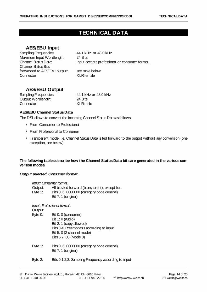
TECHNICAL DATA
AES/EBU InputSampling Frequencies: 44.1 kHz or 48.0 kHzMaximum Input Wordlength: 24 BitsChannel Status Data: Input accepts professional or consumer format.Channel Status Bitsforwarded to AES/EBU output: see table belowConnector: XLR female
AES/EBU OutputSampling Frequencies: 44.1 kHz or 48.0 kHzOutput Wordlength: 24 BitsConnector: XLR male
AES/EBU Channel Status DataThe DS1 allows to convert the incoming Channel Status Data as follows:
From Consumer to Professional
From Professional to Consumer
Transparent mode, i.e. Channel Status Data is fed forward to the output without any conversion (oneexception, see below)
The following tables describe how the Channel Status Data bits are generated in the various con-version modes.
Output selected: Consumer format.
Input: Consumer format.Output: All bits fed forward (transparent), except for:Byte 1: Bits 0..6: 0000000 (category code general)
Bit 7: 1 (original)
Input: Professional format.Output:Byte 0: Bit 0: 0 (consumer)
Bit 1: 0 (audio)Bit 2: 1 (copy allowed)Bits 3,4: Preemphasis according to inputBit 5: 0 (2 channel mode)Bits 6,7: 00 (Mode 0)
Byte 1: Bits 0..6: 0000000 (category code general)Bit 7: 1 (original)
Byte 2: Bits 0,1,2,3: Sampling Frequency according to input

OPERATING INSTRUCTIONS FOR GAMBIT DE-ESSER/COMPRESSOR DS1 TECHNICAL DATA
- Daniel Weiss Engineering Ltd., Florastr. 42, CH-8610 Uster Page 15 of 25) +41 1 940 20 06 2 +41 1 940 22 14 8 http://www.weiss.ch * [email protected]
Bits 4,5: 00 (accuaracy grade II)Bits 6,7: 00
Bytes 3..23: reserved bytes
Output selected: Professional format.
Input: Professional format.Output: All bits fed forward (transparent), except for:Byte 2: Bits 0,1,2: 001 (max. sample length= 24bit)
Bits 3,4,5: 101 (24 bit word length)Bits 6,7: 00
Input: Consumer format.Output:Byte 0: Bit 0: 1 (professional)
Bit 1: 0 (audio)Bits 2,3,4: Preemphasis according to inputBit 5: 0 (source fs locked)Bits 6,7: Sampling Frequency according to input
Byte 1: Bits 0,1,2,3: 0001 (two channel mode)Bits 4,5,6,7: 0000 (no user bit encoding)
Byte 2: Bits 0,1,2: 001 (max. sample length= 24bit)Bits 3,4,5: 101 (24 bit word length)Bits 6,7: 00
Bytes 3..12: All bits 0Byte 23: CRCC byte
Output selected: Transparent.
Input: Any format.Output: All bits fed forward (transparent), except if not bypassed:Byte 2: Bits 0,1,2: 001 (max. sample length= 24bit)
Bits 3,4,5: 101 (24 bit word length)Bits 6,7: 00

OPERATING INSTRUCTIONS FOR GAMBIT DE-ESSER/COMPRESSOR DS1 TECHNICAL DATA
- Daniel Weiss Engineering Ltd., Florastr. 42, CH-8610 Uster Page 16 of 25) +41 1 940 20 06 2 +41 1 940 22 14 8 http://www.weiss.ch * [email protected]
PowerMains Voltage: 110 / 220 Volts with voltage selectorFuse rating: 500 mA slow blowPower Consumption: 40VA max
OverloadNumber of consecutiveover-samples to cause “over” display: 1..16 settable
Peak MetersPeak meters timing for compressor input and output stage adhere to AES recommendations.
Parameter Table
Overall Gain
All numbers in dB:
- , - 90.0, -85.0, -80.0, -76.0, -72.0, -68.0, -64.0, -60.0, -56.0, -53.0, -50.0, -48.0, -46.0, -44.0, -42.0, -40.0, -39.0, -38.0, -37.0, -36.0, -35.0, -34.0, -33.0, -32.0, -31.0, -30.0, -29.5, -29.0, -28.5, -28.0, -27.5, -27.0, -26.5, -26.0, -25.5, -25.0, -24.5, -24.0, -23.5, -23.0, -22.5, -22.0, -21.5, -21.0, -20.5, -20.0, -19.5, -19.0, -18.5, -18.0, -17.5, -17.0, -16.5, -16.0, -15.5, -15.0, -14.5, -14.0, -13.5, -13.0, -12.5, -12.0, -11.5, -11.0, -10.5, -10.5, -9.5, -9.0, -8.5, -8.0, -7.5, -7.0, -6.5, -6.0, -5.8, -5.6, -5.4, -5.2, -5.0, -4.8, -4.6, -4.4, -4.2, -4.0, -3.8, -3.6, -3.4, -3.2, -3.0, -2.8, -2.6, -2.4, -2.2, -2.0, -1.8, -1.6, -1.4, -1.2, -1.0, -0.8, -0.6, -0.5, -0.4, -0.3, -0.2, -0.1, 0.0, 0.5, 1.0, 1.5, 2.0, 2.5, 3.0, 3.5, 4.0, 4.5, 5.0, 5.5, 6.0, 6.5, 7.0, 7.5, 8.0, 8.5, 9.0,9.5, 10.0
Bandwidth
All numbers are fractions of octaves:
1/6, 1/3, ½, 2/3, 5/6, 1, 11/6, 1 1/3, 1 ½, 1 2/3, 1 5/6, 21/6, 2 1/3, 2 ½, 2 2/3, 2 5/6, 31/6, 3 1/3, 3 ½, 32/3, 3 5/6, 4 1/6, 4 1/3, 4 ½, 4 2/3, 4 5/6, 51/6, 5 1/3, 5 ½, 5 2/3, 5 5/6, 6
Frequency
All numbers are Herz and are either center or cutoff frequncy:
277, 294, 311, 330, 349, 370, 392, 415, 440, 466, 494, 523, 554, 587, 622, 659, 698, 740, 784, 831, 880,932, 988, 1050, 1110, 1170, 1240, 1320, 1400, 1480, 1570, 1660, 1760, 1860, 1980, 2090, 2220, 2350,2490, 2640, 2790, 2960, 3140, 3320, 3520, 3730, 3950, 4190, 4430, 4700, 4980, 5270, 5590, 5920,

OPERATING INSTRUCTIONS FOR GAMBIT DE-ESSER/COMPRESSOR DS1 TECHNICAL DATA
- Daniel Weiss Engineering Ltd., Florastr. 42, CH-8610 Uster Page 17 of 25) +41 1 940 20 06 2 +41 1 940 22 14 8 http://www.weiss.ch * [email protected]
6270, 6640, 7040, 7460, 7900, 8370, 8870, 9400, 9960, 10500, 11200, 11800, 12500, 13300, 14100,14900, 15800, 16700, 17700
Attack, Release Delay, Release Fast & Slow, Average, Preview (when applicable):
All numbers are in seconds:
20 , 40 , 60 , 80 , 100 , 125 , 160 , 200 , 250 , 315 , 400 , 500 , 630 , 800 , 1m, 1.25m, 1.60m,2.00m, 2.50m, 3.15m, 4.00m, 5.00m, 6.30m, 8.00m, 10.0m, 12.5m, 16.0m, 20.0m, 25.0m, 31.5m, 40.0m,50.0m, 63.0m, 80.0m, 100m, 125m, 160m, 200m, 250m, 315m, 400m, 500m, 630m, 800m, 1, 1.25, 1.60,2.00, 2.50, 3.15, 4.00, 5.00, 6.30, 8.00
= 10-6
m = 10-3
Soft-knee:
0.0, 0.1, 0.2, 0.3, 0.4, 0.5, 0.6, 0.7, 0.8, 0.9, 1.0
Threshold:
All numbers are in dB:
0, -1, -2, -3, -4, -5, -6, -7, -8, -9, -10, -11, -12, -13, -14, -15, -16, -17, -18, -19, -20, -21, -22, -23, -24, -25, -26, -27, -28, -29, -30, -31, -32, -33, -34, -35, -36, -37, -38, -39, -40, -41, -42, -43, -44, -45, -46, -47,-48, -49, -50, -51, -52, -53, -54, -55, -56, -57, -58, -59, -60
Ratio:
1.00:1, 1.05:1, 1.11:1, 1.17:1, 1.25:1, 1.33:1, 1.43:1, 1.54:1, 1.67:1, 1.81:1, 2.00:1, 2.22:1, 2.50:1, 2.86:1,3.33:1, 4.00:1, 5.00:1, 6.66:1, 10:1, 20:1, 1000:1
Gain Makeup:
All numbers are in dB:
-10, -9, -8, -7, -6, -5, -4, -3, -2, -1, 0, 1, 2, 3, 4, 5, 6, 7, 8, 9, 10, 11, 12, 13, 14, 15, 16, 17, 18, 19, 20, 21,22, 23, 24, 25, 26, 27, 28, 29, 30, 31, 32, 33, 34, 35, 36, 37, 38, 39, 40, 41, 42, 43, 44, 45, 46, 47, 48, 49,50, 51, 52, 53, 54, 55, 56, 57, 58, 59, 60
off, max.

OPERATING INSTRUCTIONS FOR GAMBIT DE-ESSER/COMPRESSOR DS1 TECHNICAL DATA
- Daniel Weiss Engineering Ltd., Florastr. 42, CH-8610 Uster Page 18 of 25) +41 1 940 20 06 2 +41 1 940 22 14 8 http://www.weiss.ch * [email protected]
DitherDithering algorithm is implemented using second order noise shaping, as can be seen in Graph 12.
Graph 12: Output spectrum with 80dBFS / 1kHz sine wave, dithered to 16 Bits
Remote
MIDI Implementation
System Inclusive
All band parameters plus the controls parameters are remote controllable. Each parameter has its corre-sponding MIDI controller number.
According to the different parameters, the controllers are limited in their range. Invalid values are replacedby the maximum allowable value. Following is a list of the supported MIDI commands:
Action MIDI Message Status Byte Data Byte(s) CommentRestore Snapshot Program Change 1100 cccc 0ppp pppp (cccc) Channel No.
(ppppppp) New Prog No: 0 - 127
Center Frequency Control Change 1011 cccc 00000000 ($00) (cccc) Channel No.0vvv vvvv (vvvvvvv) New Value:
0 - 72
Bandwidth Control Change 1011 cccc 00000001($01) (cccc) Channel No.0vvv vvvv (vvvvvvv) New Value:
1 - 36
Filter Mode Control Change 1011 cccc 00000010 ($02) (cccc) Channel No.0vvv vvvv (vvvvvvv) New Value:
0= limiter, 1= Bandpass,
2 = Lowpass, 3 = Hipass
Predelay Control Change 1011 cccc 00000011 ($03) (cccc) Channel No.0vvv vvvv (vvvvvvv) New Value:
0 - 37
Attack Control Change 1011 cccc 00000100 ($04) (cccc) Channel No.

OPERATING INSTRUCTIONS FOR GAMBIT DE-ESSER/COMPRESSOR DS1 TECHNICAL DATA
- Daniel Weiss Engineering Ltd., Florastr. 42, CH-8610 Uster Page 19 of 25) +41 1 940 20 06 2 +41 1 940 22 14 8 http://www.weiss.ch * [email protected]
0vvv vvvv (vvvvvvv) New Value:
0 - 43
Release Delay Control Change 1011 cccc 00000101 ($05) (cccc) Channel No.0vvv vvvv (vvvvvvv) New Value:
0 - 53
Release Fast Control Change 1011 cccc 00000110 ($06) (cccc) Channel No.0vvv vvvv (vvvvvvv) New Value:
0 - 53
Average Control Change 1011 cccc 00000111 ($07) (cccc) Channel No.0vvv vvvv (vvvvvvv) New Value:
0 - 53
Release Slow Control Change 1011 cccc 00001000 ($08) (cccc) Channel No.0vvv vvvv (vvvvvvv) New Value:
0 - 53
Soft Knee Control Change 1011 cccc 00001001 ($09) (cccc) Channel No.0vvv vvvv (vvvvvvv) New Value:
0 - 10
Gain Makeup Mode Control Change 1011 cccc 00001010 ($0A) (cccc) Channel No.0vvv vvvv (vvvvvvv) New Value:
0= off, 1 = manual, 2= maximum
Ratio Control Change 1011 cccc 00001011 ($0B) (cccc) Channel No.0vvv vvvv (vvvvvvv) New Value:
0 - 20
Threshold Control Change 1011 cccc 00001100 ($0C) (cccc) Channel No.0vvv vvvv (vvvvvvv) New Value:
0 - 60
Gain Makeup Control Change 1011 cccc 00001101 ($0D) (cccc) Channel No.0vvv vvvv (vvvvvvv) New Value:
0 - 70
Output Gain Control Change 1011 cccc 00001110 ($0E) (cccc) Channel No.0vvv vvvv (vvvvvvv) New Value:
0 - 127
Bypass Control Change 1011 cccc 00001111 ($0F) (cccc) Channel No.0vvv vvvv (vvvvvvv) New Value:
0= off, 1 = on
A-B Select Control Change 1011 cccc 00010000 ($10) (cccc) Channel No.0vvv vvvv (vvvvvvv) New Value:
0= WS A, 1 = WS B
Monitor Control Change 1011 cccc 00010010 ($12) (cccc) Channel No.0vvv vvvv (vvvvvvv) New Value:
0= off, 1 = on
System Reset 1111 1111 - Recall Snapshot 0 to WS A

OPERATING INSTRUCTIONS FOR GAMBIT DE-ESSER/COMPRESSOR DS1 TECHNICAL DATA
- Daniel Weiss Engineering Ltd., Florastr. 42, CH-8610 Uster Page 20 of 25) +41 1 940 20 06 2 +41 1 940 22 14 8 http://www.weiss.ch * [email protected]
System Exclusive
Snapshot format:
Bytecount Value Description
1 F0 Sysex Header
2 00 Manufacturer's ID
3 30 Manufacturer's ID
4 5A Manufacturer's ID
5 08 Model ID: 8 = Gambit DS1
6 0000nnnn Device ID: -> Midi channel number
7 00000001 message = Snapshot dump Message Type 1
8 0nnnnnnn Package number ( 0..7F) Data
9 0nnnnnnn scale set number
10 - 24 0nnnnnnn 15 Bytes of Snapshot data
25 0ccccccc Checksum without byte one (F0 Sysex Command) Checksum
26 F7 EOS EOS
Dump request:
Bytecount Value Description
1 F0 Sysex Header
2 00 Manufacturer's ID
3 30 Manufacturer's ID
4 5A Manufacturer's ID
5 08 Model ID: 8 = Gambit DS1
6 0000nnnn Device ID: -> Midi channel number
7 00000010 message = dump request Message Type 2
8 F7 EOS EOS
Version request:
Bytecount Value Description
1 F0 Sysex Header
2 00 Manufacturer's ID
3 30 Manufacturer's ID
4 5A Manufacturer's ID
5 08 Model ID: 8 = Gambit DS1
6 0000nnnn Device ID: -> Midi channel number
7 00000011 message = version request Message Type 3
8 F7 EOS EOS

OPERATING INSTRUCTIONS FOR GAMBIT DE-ESSER/COMPRESSOR DS1 TECHNICAL DATA
- Daniel Weiss Engineering Ltd., Florastr. 42, CH-8610 Uster Page 21 of 25) +41 1 940 20 06 2 +41 1 940 22 14 8 http://www.weiss.ch * [email protected]
Version send:
Bytecount Value Description
1 F0 Sysex Header
2 00 Manufacturer's ID
3 30 Manufacturer's ID
4 5A Manufacturer's ID
5 08 Model ID: 8 = Gambit DS1
6 0000nnnn Device ID: -> Midi channel number
7 00000100 message = send version Message Type 4
8 00000100 OS Version data
9 00000100 DSP Version
10 00000100 Scale Version
11 00000100 Coeff. Version
12 F7 EOS EOS
PC programming mode:
Bytecount Value Description
1 F0 Sysex Header
2 00 Manufacturer's ID
3 30 Manufacturer's ID
4 5A Manufacturer's ID
5 08 Model ID: 8 = Gambit DS1
6 0000nnnn Device ID: -> Midi channel number
7 00000101 message = pc programming mode Message Type 5
12 F7 EOS EOS

OPERATING INSTRUCTIONS FOR GAMBIT DE-ESSER/COMPRESSOR DS1 TECHNICAL DATA
- Daniel Weiss Engineering Ltd., Florastr. 42, CH-8610 Uster Page 22 of 25) +41 1 940 20 06 2 +41 1 940 22 14 8 http://www.weiss.ch * [email protected]
Addendum to the Manuals of the Gambit Series DS1 and DS1-MK2DeEsser / Compressor / Limiter
The graphs on the pages below have been made to convey a better understanding of the dynamic parameters of theGambit DS1 DeEsser/Compressor.
Please also read the appropriate pages in the DS1 / DS1-MK2 manual to have a proper understanding of the sidechainprocess.
The test signal is a repeating sine wave burst with a certain "on" and a certain "off" level. The frequency of the sine waveis above 10kHz (period less than 100 s), so there is no influence of the sine wave frequency on the timing behaviour.
The table below shows the timing parameters set on the DS1. For the static parameters a threshold of -20dB, a1000:1 ratio and no softknee have been chosen.
Figure Preview Attack Rel.Delay Rel.Fast Average Rel.Slow burst duty cycle
1 bypass
2 20 s 20ms 20 s 200ms 800ms 1s 50%
3 63ms " " " " " "
4 " " " " " 200ms "
5 " " 5ms " " " "
6 " " 20ms " " " "
7 " " " 25ms " 500ms 0.5%
8 " " " " " " 2%
9 " " " " " " 5%
10 " " " " " " 10%
11 " " " " 40ms " 0.5%
12 " " " " " " 2%
13 " " " " " " 5%
14 " " " " " " 10%

OPERATING INSTRUCTIONS FOR GAMBIT DE-ESSER/COMPRESSOR DS1 TECHNICAL DATA
- Daniel Weiss Engineering Ltd., Florastr. 42, CH-8610 Uster Page 23 of 25) +41 1 940 20 06 2 +41 1 940 22 14 8 http://www.weiss.ch * [email protected]
Fig. 1 Fig. 2
Fig. 1 Bypass, this is how the 50% dutycycle sinewave burst looks like. X-axis shows time in milliseconds, Y-axis showslinear level in percentage of full scale. Just like a scope.
Fig. 2 A very short preview time combined with a long attack time cause an overshoot at the onstart of the burst. Asthe sidechain reacts to the input signal (slowly because of the long attack time) the level of the burst is brought to theanticipated level.
Fig. 3 Fig. 4
Fig. 3 The preview time is now about three times the attack time, which gives the sidechain a headstart on the audiosignal. The result is a proper limiting without overshoot.
Fig. 4 As useful the preview facility in Fig 3 is, it can have an unwanted effect at the release portion. A relatively shortrelease time causes the release to show up during the last milliseconds of the burst. This because the sidechain "sees"the "burst off" before the gain stage sees it (preview delay), so the end of the burst gets influenced by the release.

OPERATING INSTRUCTIONS FOR GAMBIT DE-ESSER/COMPRESSOR DS1 TECHNICAL DATA
- Daniel Weiss Engineering Ltd., Florastr. 42, CH-8610 Uster Page 24 of 25) +41 1 940 20 06 2 +41 1 940 22 14 8 http://www.weiss.ch * [email protected]
Fig. 5 Fig. 6
Figs. 5 and 6 The effect described in Fig. 4 can be eliminated with the Release Delay parameter. The release is delayedfor a certain time and thus can not influence the end of the burst anymore. In Fig 5 the release delay is not quite longenough, while in Fig. 6 there is no release influence visible anymore.
Fig. 7 Fig. 8
The following figures show the effect of the automatic release time algorithm and the Average parameter.
Fig. 7 A very short burst duration, like a short peak in the music. The Release Fast, Average and Release Slow parame-ters are set to typical values. Fig. 7 shows that after a short peak the Release Fast time is chosen, so that the short peakdoes not have much influence on the programme after it.
Fig. 8 The burst is now longer which gives it more influence on the average measurement (averaging oft he signal). Firstthere is a Release Fast portion followed by a short segment of Release Slow.

OPERATING INSTRUCTIONS FOR GAMBIT DE-ESSER/COMPRESSOR DS1 TECHNICAL DATA
- Daniel Weiss Engineering Ltd., Florastr. 42, CH-8610 Uster Page 25 of 25) +41 1 940 20 06 2 +41 1 940 22 14 8 http://www.weiss.ch * [email protected]
Fig. 9 Fig. 10
Fig. 9 The burst is even longer, causing a longer Release Slow portion.
Fig. 10 Still longer burst, with even longer Release Slow portion.
Fig. 11 Fig. 12
Figs. 11 to 14 For these figures the Average time is relatively short, causing the average measurement value to followthe peak measurement more quickly than with Fig. 7 to 10. The effect is that depending on the burst length, there isnot that much of an influence of the Release Slow parameter as it was with figures 7 to 10.
Fig. 13 Fig. 14