drive application software - ab. · pdf filemaintenance of solid-state ... diameter...
TRANSCRIPT

Drive Application Software Function Module Diameter Calculation Imperial Units Reference Manual

FM – Inertia Compensation
Application Software – page 2 of 30
Important User Information
Users of this Reference Manual must be familiar with the application this Function Module is intended to support and its usage. Function Modules intended usage are as a building blocks for a created application. The user must be familiar with the programming tools used to implement this module, the program platform to be used in the application, and the Rockwell Automation drive products to be controlled in the application. Because of the variety of uses for the products described in this publication, those responsible for the application and use of this control equipment must satisfy themselves that all necessary steps have been taken to assure that each application and use meets all performance and safety requirements, including any applicable laws, regulations, codes and standards. The illustrations, charts, sample programs and layout examples shown in this guide are intended solely for purposes of example. Since there are many variables and requirements associated with any particular installation, Rockwell Automation does not assume responsibility or liability (to include intellectual property liability) for actual use based upon the examples shown in this publication. Rockwell Automation publication SGI-1.1, Safety Guidelines for the Application, Installation, and Maintenance of Solid-State Control (available from your local Rockwell Automation office), describes some important differences between solid-state equipment and electromechanical devices that should be taken into consideration when applying products such as those described in this publication. Reproduction of the contents of this copyrighted publication, in whole or in part, without written permission of Rockwell Automation, is prohibited.
Trademarks RSLogix5000 is a trademark of Rockwell Automation PowerFlex is a trademark of Rockwell Automation

FM – Diameter Calculation
Drive Application Software – page 3 of 30
Table of Contents
1.0 Precautions ............................................................................................................5
2.0 Definitions ..............................................................................................................6
2.1 Conventions..........................................................................................................6
2.2 Normalized Quantities...........................................................................................6
2.3 Terminology ..........................................................................................................7 2.3.1 Web .................................................................................................................................... 7 2.3.2 Strip .................................................................................................................................... 7 2.3.3 Drive ................................................................................................................................... 7 2.3.4 Motor Torque....................................................................................................................... 7 2.3.5 Section................................................................................................................................ 7
3.0 Overview.................................................................................................................8
3.1 Diameter effects on surface speed .......................................................................8
3.2 Diameter effects on surface tension......................................................................9
4.0 Functional Description ........................................................................................10
4.1 Overview.............................................................................................................10 4.1.1 Main routine .......................................................................................................................10 4.1.2 DiamPreset routine.............................................................................................................10 4.1.3 DiamCalc routine................................................................................................................10
4.2 Main routine ........................................................................................................10
4.3 DiamPreset routine .............................................................................................11 4.3.1 Preset1Cmmd ....................................................................................................................11 4.3.2 Preset2Cmmd ....................................................................................................................11 4.3.3 Preset3Cmmd ....................................................................................................................11 4.3.4 Preset1Val_in.....................................................................................................................12 4.3.5 Preset2Val_in.....................................................................................................................12 4.3.6 Preset3Val_in.....................................................................................................................12 4.3.7 PresetIncCmmd..................................................................................................................12 4.3.8 PresetDecCmmd................................................................................................................12 4.3.9 PresetIncDecRate_inSec....................................................................................................12 4.3.10 DiamPresetCmmd..............................................................................................................12 4.3.11 DiamPresetVal_in...............................................................................................................13
4.4 DiamCalc routine ................................................................................................13 4.4.1 CalcEnbl.............................................................................................................................14 4.4.2 CalcEnblThresh_FPM.........................................................................................................15 4.4.3 CalcUpdate_Rev ................................................................................................................15 4.4.4 SpeedLine_FPM.................................................................................................................15 4.4.5 SpeedMotor_Rpm ..............................................................................................................15 4.4.6 GearRatio...........................................................................................................................15 4.4.7 DiamMinEC_in ...................................................................................................................15 4.4.8 DiamFR_in .........................................................................................................................15 4.4.9 DiamMeasEnbl ...................................................................................................................16 4.4.10 DiamMeasInput ..................................................................................................................16 4.4.11 DiamMeasMin_DC .............................................................................................................16 4.4.12 DiamMeasMax_DC ............................................................................................................16 4.4.13 DiamMeasMin_in................................................................................................................16 4.4.14 DiamMeasMax_in...............................................................................................................16

FM – Inertia Compensation
Drive Application Software – page 4 of 30
4.4.15 DiamPresetCmmd..............................................................................................................16 4.4.16 DiamPresetVal_in ..............................................................................................................16 4.4.17 DiamRate_inRev ................................................................................................................17 4.4.18 DiamIncEnbl.......................................................................................................................17 4.4.19 DiamDecEnbl .....................................................................................................................17 4.4.20 DiamCalc_in.......................................................................................................................17 4.4.21 RadiusCalc_ft.....................................................................................................................17 4.4.22 BuildUpRatio......................................................................................................................18 4.4.23 BuildUpRatioRec................................................................................................................18 4.4.24 DiamMeas_in.....................................................................................................................18 4.4.25 Constant_RPMperFPM ......................................................................................................18 4.4.26 Constant_RPMperFPM ......................................................................................................18
5.0 Setup / Configuration ..........................................................................................19
5.1 Overview.............................................................................................................19
5.2 DiamPreset JSR Instruction................................................................................19 5.2.1 Input Parameters................................................................................................................19 5.2.2 Return Parameters.............................................................................................................19 5.2.3 Default Tags used in Drive Application Software.................................................................20
5.3 DiamCalc JSR Instruction...................................................................................20 5.3.1 Input Parameters................................................................................................................20 5.3.2 Return Parameters.............................................................................................................21 5.3.3 Default Tags used in Drive Application Software.................................................................22
6.0 Tuning / Startup ...................................................................................................23
6.1 Installing the Application Module ........................................................................23
6.2 Drive Tuning & Configuration..............................................................................23
6.3 Offline Tuning / Startup.......................................................................................24
6.4 Online Tuning / Startup.......................................................................................24 6.4.1 Measured Diameter Enable True........................................................................................24 6.4.2 Measured Diameter Enable False (typical configuration).....................................................24
Appendix A - Process Line Command & Status Words..........................................26
Appendix B - Block Diagram.....................................................................................28
Appendix C - Parameter (Tag) Table ........................................................................29

FM – Diameter Calculation
Drive Application Software – page 5 of 30
1.0 Precautions
Class 1 LED Product
ATTENTION: Hazard of permanent eye damage exists when using optical transmission equipment. This product emits intense light and invisible radiation. Do not look into module ports or fiber optic cable connectors.
General Precautions
ATTENTION: This drive contains ESD (Electrostatic Discharge) sensitive parts and assemblies. Static control precautions are required when installing, testing, servicing or repairing this assembly. Component damage may result if ESD control procedures are not followed. If you are not familiar with static control procedures, reference Allen Bradley publication 8000-4.5.2, “Guarding Against Electrostatic Damage” or any other applicable ESD protection handbook.
ATTENTION: An incorrectly applied or installed drive can result in component damage or a reduction in product life. Wiring or application errors such as under sizing the motor, incorrect or inadequate AC supply, or excessive surrounding air temperatures may result in malfunction of the system.
ATTENTION: Only qualified personnel familiar with the PowerFlex 700S AC Drive and associated machinery the products control should plan, program, configure, or implement the installation, start-up and subsequent maintenance of the system / product. Failure to comply may result in personal injury and/or equipment damage. ATTENTION: To avoid an electric shock hazard, verify that the voltage on the bus capacitors has discharged before performing any work on the drive. Measure the DC bus voltage at the +DC & –DC terminals of the Power Terminal Block (refer to Chapter 1 in the PowerFlex 700S User Manual for location). The voltage must be zero.
ATTENTION: Risk of injury or equipment damage exists. DPI or SCANport host products must not be directly connected together via 1202 cables. Unpredictable behavior can result if two or more devices are connected in this manner.
ATTENTION: Risk of injury or equipment damage exists. Parameters 365 [Encdr0 Loss Cnfg] - 394 [VoltFdbkLossCnfg] let you determine the action of the drive in response to operating anomalies. Precautions should be taken to ensure that the settings of these parameters do not create hazards of injury or equipment damage.
ATTENTION: Risk of injury or equipment damage exists. Parameters 383 [SL CommLoss Data] - 392 [NetLoss DPI Cnfg] let you determine the action of the drive if communications are disrupted. You can set these parameters so the drive continues to run. Precautions should be taken to ensure the settings of these parameters do not create hazards of injury or equipment damage.

FM – Inertia Compensation
Drive Application Software – page 6 of 30
2.0 Definitions A Function Module [FM] is a base program designed to perform a specific function (operation) in an application. Function Modules are not complete applications and will require additional programming to control a machine section. The additional programming required for the application and configuration of the overall application is the responsibility of the user. An Application Module [AM] is a complete program designed to perform a specific machine sections application (task). Application Modules are complete programs and only require configuration setup in order to perform the designated tasks.
2.1 Conventions The conventions described below are used in programming and documentation of Function Modules and Application Modules.
1. All FM tags are program scoped. 2. All user connections to the FM are through the Jump to Sub-Routine (JSR)
instruction input and return parameters. 3. Users cannot edit Function Modules. 4. Data format
Data Type RSLogix Type Format Range Example B = Boolean BOOL x 0 to 1 0 or 1 I = Integer INT x +/- 32767 8947 D = Double INT DINT x +/- 2097151 74364 R = Real (Float) REAL x.x +/-16777215* 3.4 / 13.0
* = Applies to single precision accuracy.
2.2 Normalized Quantities Often a physical quantity is normalized by dividing the physical quantity by a base quantity with the same engineering units as the physical quantity. As a result, the normalized quantity does not have units, but is ‘expressed per-unit’. The normalized quantity has a value of 1.0 [per-unit] when the physical quantity has a value equal to the base quantity. A good example of this is the physical quantity of motor current. The information that the motor is drawing 40 amps has little significance. The motor nameplate states that the rated motor current is 30 amps. The motor is drawing 133% current is significant information. In the previous illustration the quantity of motor amps was normalized to 133%. In per unit, the quantity is normalized to 1.33.

FM – Diameter Calculation
Drive Application Software – page 7 of 30
2.3 Terminology
2.3.1 Web A web is defined as the material that is being transported through the machine. A web is sometimes referred to as “sheet” or “strip”.
2.3.2 Strip The strip is defined as the material that is being transported through the machine. A web is sometimes referred to as “sheet” or “web”. The term “strip tension” is referencing the tension of the material in the machine.
2.3.3 Drive The drive is the power device that is transmitting power to the motor. The motor is connected to a mechanical device that is propelling the material. This manual is specific to the PowerFlex 700S drive.
2.3.4 Motor Torque A D.C. Motor has two currents flowing through it. The first current is the flux, also known as the field current. This is the magnetizing current that allows the motor to produce torque. The second current is the armature current. This is the actual torque producing current of the motor. An A.C. motor has only one current physically flowing through the machine. However, this current is a combination of both magnetizing and torque producing current. Motor Torque on an AC motor is the torque producing portion of the total current flowing through the motor.
2.3.5 Section A Web Handling Machine is broken up into sections. A section consists of one or more drives used to propel the material through the line. An Unwind Section could consist of one drive, one motor, and one spindle A lead Section could consist of more than one drive and one motor combination. This could consist of line pacer and then several helper drives. The helper drives “help” in transporting the strip through the machine. Typically when more than one drive is in a section, one drive is the leader and the other drive is the follower. The follower typically follows the leader’s torque reference.

FM – Inertia Compensation
Drive Application Software – page 8 of 30
3.0 Overview Diameter calculation is the process by which a dynamically changing roll diameter is mathematically calculated during machine operation. In center driven winding and unwinding applications, the actual diameter of the driven section changes as product is wound about the axis or unwound from the axis. As the diameter of the driven section changes it is necessary to change the axial speed and torque in order to maintain constant surface speed and tension on the product. Diameter calculation can also be used to calculate the change in total reflected inertia. This is typically used to profile the speed loop gain and in inertia compensation.
3.1 Diameter effects on surface speed If the rotational speed of the driven section is kept constant, the surface speed will increase as the diameter of the section increases. To maintain constant surface speed, the rotational speed must decrease proportional to the increase in roll diameter. If the roll diameter doubles, the rotational speed must be reduced by half to maintain constant surface speed.
0200400600800
100012001400160018002000
4 8 12 16 20 24 28 32 36 40 44 48 52
Roll Diameter (in)
Sp
eed Motor Speed (Rpm)
Surface Spd (Fpm)
*GearRatioer(ft)*pRollDiametFpm)LineSpeed(
(Rpm)MotorSpeed
12er(in)RollDiamet
er(ft)RollDiamet
=
=

FM – Diameter Calculation
Drive Application Software – page 9 of 30
3.2 Diameter effects on surface tension If the torque applied to a driven section is kept constant, the tension applied to the product at the surface of the roll will decrease as the diameter of the driven section increases. To maintain constant tension on the product, the torque must be increased proportional to the change in diameter. If the roll diameter doubles the torque applied must double to maintain constant product tension at the surface of the roll.
0
20
40
60
80
100
120
4 8 12 16 20 24 28 32 36 40 44 48 52
Roll Diameter
To
rqu
e / T
ensi
on
Surface Tension (lbs)
Motor Torque (lbft)
GearRatioon(lbs)(ft)*TensiRollRadius
e(lbft)MotorTorqu
2er(ft)RollDiamet
(ft)RollRadius
12er(in)RollDiamet
er(ft)RollDiamet
=
=
=

FM – Inertia Compensation
Drive Application Software – page 10 of 30
4.0 Functional Description
4.1 Overview The Diameter Calculation Function Module consists of a program with three routines in RSLogix 5000. The three routines are the Main, DiamPreset, & DiamCalc. These routines are dependent on one another and may not be separated. The user may edit the Main routine to connect signals (tags) and configure the FM. The user cannot edit the DiamPreset or DiamCalc routines.
4.1.1 Main routine The Main routine is where the user connects user created controller tags to the input and output program tags of the FM. These links are created in the Jump to Sub-Routine (JSR) instructions. One JSR is used to call the DiamPreset routine and another JSR is used to call the DiamCalc routine.
4.1.2 DiamPreset routine The DiamPreset routine is used to select and command a preset value to the diameter calculator. Diameter preset is used to “reset” the roll diameter to a preset value such as core diameter as used in winder applications or to the starting roll diameter as used in unwind applications. If the diameter calculator is not preset to the correct starting roll diameter, the machine control may not function correctly.
4.1.3 DiamCalc routine The DiamCalc routine is where the diameter is actually calculated. The diameter is calculated by measuring the distance of web wound onto the roll for a given number of roll revolutions. Setting the number of roll revolutions to a whole number, helps avoid variations in diameter calculation with eccentric rolls.
4.2 Main routine The Main routine consists of two rungs of ladder logic programming. A rung description briefly describes the Input and Return (output) parameters of the JSR instructions for each routine called. Temporary tags have been entered for each input parameter and each return parameter. The tag names entered in the JSR’s are not declared. The user must replace these tag names with existing project tags or create new tags. The routine will show an error until all input and return parameters are satisfied. The input parameters may also be entered as actual values. If an input parameter is set to a value and not a tag, the value cannot be edited in run mode. Values entered directly in the JSR should be constants that do not change during machine operation. Specific formatting is required for values entered directly in the JSR. NOTE: For Application Module users, the tags in the JSR’s are predefined and configured for operation. No additional integration is necessary.
Data Type Format Example B = Boolean x 0 or 1 I = Integer x 123 R = Real (Float) x.x 3.4 / 13.0
If any signal scaling is required to interface the FM into the user application, the user may use the main routine for this programming. Note; any scaling for inputs to the routines should be done before the JSR and any scaling applied to the return values from the routines should be done after the JSR. Below are descriptions of each parameter required for use of the Diameter Calculation FM.

FM – Diameter Calculation
Drive Application Software – page 11 of 30
4.3 DiamPreset routine The diameter preset routine is designed for applications where the diameter calculator will be preset to one of several preset diameters or where a preset increase/decrease function is required. If only a single diameter preset is required, this routine and the JSR instruction can be deleted. If the DiamPreset routine is deleted, the (DiamCalc – In15 & In16) inputs [yDiamPresetCmmd] & [yDiamPresetVal_in] must be controlled by the user’s custom programming. If the diameter is not properly preset, the machine section may not be able to regulate product tension in the process. Input Parameters
Name Type Range Description 1 Preset1Cmmd BOOL 0 to 1 Preset diameter to Preset1Val_in 2 Preset2Cmmd BOOL 0 to 1 Preset diameter to Preset2Val_in 3 Preset3Cmmd BOOL 0 to 1 Preset diameter to Preset3Val_in 4 Preset1Val_in REAL 0 to 500 Value of Preset 1 5 Preset2Val_in REAL 0 to 500 Value of Preset 2 6 Preset3Val_in REAL 0 to 500 Value of Preset 3 7 PresetIncCmmd BOOL 0 to 1 Manual Diameter Increase 8 PresetDecCmmd BOOL 0 to 1 Manual Diameter Decrease
9 PresetIncDecRate_inSec REAL 0 to 10 Manual Diameter Increase/Decrease Rate adjustment
Return Parameters
Name Type Range Description
1 DiamPresetCmmd BOOL 0 to 1 Diameter Preset Command to DiamCalc routine
2 DiamPresetVal_in REAL 0 to 500 Diameter Preset Value to DiamCalc routine
4.3.1 Preset1Cmmd This input is the command to the routine to select the Preset1Val_in as the output DiamPresetVal_in. When this input is high and EnablePresets is high the DiamPresetCmmd will be set high and the DiamPresetVal_in will be set equal to Preset1Val_in. Usage – Use this input to activate the value of Preset1Val_in as the preset input to the DiamCalc routine.
4.3.2 Preset2Cmmd This input is the command to the routine to select the Preset2Val_in as the output DiamPresetVal_in. When this input is high and EnablePresets is high the DiamPresetCmmd will be set high and the DiamPresetVal_in will be set equal to Preset2Val_in. Usage – Use this input to activate the Preset2Val_in as the preset value of the DiamCalc routine.
4.3.3 Preset3Cmmd This input is the command to the routine to select the Preset3Val_in as the output DiamPresetVal_in. When this input is high and EnablePresets is high the DiamPresetCmmd will be set high and the DiamPresetVal_in will be set equal to Preset3Val_in. Usage – Use this input to activate the Preset3Val_in as the preset value of the DiamCalc routine.
FM – Inertia Compensation
Drive Application Software – page 12 of 30
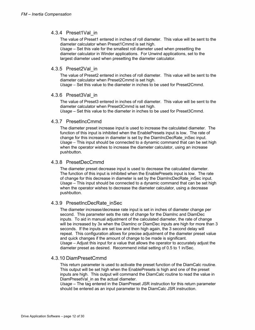
4.3.4 Preset1Val_in The value of Preset1 entered in inches of roll diameter. This value will be sent to the diameter calculator when Preset1Cmmd is set high. Usage – Set this vale for the smallest roll diameter used when presetting the diameter calculator in Winder applications. For Unwind applications, set to the largest diameter used when presetting the diameter calculator.
4.3.5 Preset2Val_in The value of Preset2 entered in inches of roll diameter. This value will be sent to the diameter calculator when Preset2Cmmd is set high. Usage – Set this value to the diameter in inches to be used for Preset2Cmmd.
4.3.6 Preset3Val_in The value of Preset3 entered in inches of roll diameter. This value will be sent to the diameter calculator when Preset3Cmmd is set high. Usage – Set this value to the diameter in inches to be used for Preset3Cmmd.
4.3.7 PresetIncCmmd The diameter preset increase input is used to increase the calculated diameter. The function of this input is inhibited when the EnablePresets input is low. The rate of change for this increase in diameter is set by the DiamIncDecRate_inSec input. Usage – This input should be connected to a dynamic command that can be set high when the operator wishes to increase the diameter calculator, using an increase pushbutton.
4.3.8 PresetDecCmmd The diameter preset decrease input is used to decrease the calculated diameter. The function of this input is inhibited when the EnablePresets input is low. The rate of change for this decrease in diameter is set by the DiamIncDecRate_inSec input. Usage – This input should be connected to a dynamic command that can be set high when the operator wishes to decrease the diameter calculator, using a decrease pushbutton.
4.3.9 PresetIncDecRate_inSec The diameter increase/decrease rate input is set in inches of diameter change per second. This parameter sets the rate of change for the DiamInc and DiamDec inputs. To aid in manual adjustment of the calculated diameter, the rate of change will be increased by 3x when the DiamInc or DiamDec inputs are high for more than 3 seconds. If the inputs are set low and then high again, the 3 second delay will repeat. This configuration allows for precise adjustment of the diameter preset value and quick changes if the amount of change to be made is significant. Usage – Adjust this input for a value that allows the operator to accurately adjust the diameter preset as desired. Recommend initial setting of 0.5 to 1 in/Sec.
4.3.10 DiamPresetCmmd This return parameter is used to activate the preset function of the DiamCalc routine. This output will be set high when the EnablePresets is high and one of the preset inputs are high. This output will command the DiamCalc routine to read the value in DiamPresetVal_in as the actual diameter. Usage – The tag entered in the DiamPreset JSR instruction for this return parameter should be entered as an input parameter to the DiamCalc JSR instruction.

FM – Diameter Calculation
Drive Application Software – page 13 of 30
4.3.11 DiamPresetVal_in This return parameter is used as the value to preset the diameter calculation when the DiamPresetCmmd is high. Usage - The tag entered in the DiamPreset JSR instruction for this return parameter should be entered as an input parameter to the DiamCalc JSR instruction.
4.4 DiamCalc routine The diameter calculation routine is the heart of this function module. The routine includes programming for the diameter calculator, programming to scale an external measurement of diameter, and scaled outputs for referencing to the drive and to other function modules. The module has been configured for operation in Imperial units. All data must be entered in the units specified by the tags. If the line speed is not directly available in FPM, the user must scale the line speed reference to FPM. The programming for this may be entered in the main routine and should be executed before the JSR instruction for the DiamCalc routine. Example equations for converting the line speed reference to FPM are below. Note: The change in diameter or actual roll diameter should not be used in the calculation of Line Speed. The Line Speed input parameter (DiamCalc routine – In4) must be an independent source of line speed, not the spindle rotational speed converted to line speed (using the calculated diameter).
Typically, line speed reference is used for the diameter calculator line speed input. If the line speed reference is not available, a line speed feedback signal from an adjacent fixed diameter drive or a surface tachometer can also be used. The externally measured diameter may be used for the calculated diameter output. It is recommended to utilize the Diameter Calculation FM when measuring the actual diameter with an external device. Using the FM will provide rate of change limits to prevent step changes in the diameter or errors in the external measurement device from instantaneously changing the output diameter value used in the speed reference to the machine section. If the measured diameter output, scaled in inches, is programmed as one of the three preset inputs, the measured diameter can be used as a preset.
)eSpeed(Mpm3.2804*LinFpm)LineSpeed(
peed(Yph)0.05*LineSFpm)LineSpeed(
d(Ypm)3*LineSpeeFpm)LineSpeed(
n/min)ineSpeed(i0.083333*LFpm)LineSpeed(
12m(in)*pMinCoreDia
*GearRatio
tr(Rpm)LineSpeedMFpm)LineSpeed(
=
=
=
=
=

FM – Inertia Compensation
Drive Application Software – page 14 of 30
Input Parameters Name Type Range Description
1 CalcEnbl BOOL 0 to 1 Enable the Diameter Calculation 2 CalcEnblThresh_FPM REAL 0 to 50 Diameter Calc low speed thresh hold 3 CalcUpdate_Rev REAL 1 to 200 Number of revolutions per length count 4 SpeedLine_FPM REAL +/- 5000 Line Speed 5 SpeedMotor_RPM REAL +/- 7200 Actual motor speed 6 GearRatio REAL 1 to 100 Motor RPM / Roll RPM 7 DiamMinEC_in REAL 0 to FR Minimum diameter Empty Core
8 DiamFR_in REAL MinEC to 500 Full Roll diameter
9 DiamMeasEnbl BOOL 0 to 1 Use DiamMeas value for actual Diam 10 DiamMeasInput REAL NA Measured diameter input (Raw data) 11 DiamMeasMin_DC REAL NA Raw data minimum 12 DiamMeasMax_DC REAL NA Raw data maximum 13 DiamMeasMin_in REAL 0 to 500 Actual diameter at DiamMeasMin_DC 14 DiamMeasMax_in REAL 0 to 500 Actual diameter at DiamMeasMax_DC 15 yDiamPresetCmmd BOOL 0 to 1 Preset command from DiamPreset 16 yDiamPresetVal_in REAL 0 to 500 Preset value form DiamPreset 17 DiamRate_inRev REAL 0.00 to 1 Max allowed diameter rate of change 18 DiamIncEnbl BOOL 0 to 1 Allow diameter calc to increment 19 DiamDecEnbl BOOL 0 to 1 Allow diameter calc to decrement Return Parameters
Name Type Range Description 1 DiamCalc_in REAL 0 to 500 Actual calculated diameter 2 RadiusCalc_ft REAL 0 to 21 Actual calculated radius 3 BuildUpRatio REAL 1 to 20 Ratio of actual diameter to min core 4 BuildUpRatioRec REAL 0.05 to 1 (1 / BuildUpRatio) 5 DiamMeas_in REAL 0 to 500 Scaled value of measured diameter
6 Constant_RPMperFPM REAL NA Scaling constant FPM to minimum empty core RPM
4.4.1 CalcEnbl The CalcEnbl input enables the diameter calculator. When the input is low, the DiamCalc_in output will maintain its last value, unless the Measured Diameter Enable input parameter (DiamCalc – In9) is true. If a preset is commanded, the DiamCalc_in output will be updated to the preset value. When the input is high, the DiamCalc_in output will be calculated based on line speed and the number of roll rotations. If the line speed input is below CalcEnblThresh_FPM, the DiamCalc_in output will be held at last value, regardless of the CalcEnbl state. Usage – This input should be set high when the section is in run and the line speed input represents roll surface speed (e.g. web tension control is on (Dancer / Tension / Torque). The diameter calculator is typically disabled if some form of tension control is not active.

FM – Diameter Calculation
Drive Application Software – page 15 of 30
4.4.2 CalcEnblThresh_FPM This input adjusts the minimum line speed in FPM that the diameter calculation will be active. The diameter calculation will be disabled if the line speed is below the CalcEnbleThresh_FPM. The diameter calculation should be disabled at low line speed to prevent errors in the calculation. Usage – Typically a setting of 1% to 5% of line speed will work well.
4.4.3 CalcUpdate_Rev This input adjusts the number of roll revolutions per diameter calculation. The calculator will measure the length of web accumulated at the set number of revolutions. A greater number of revolutions will naturally average the roll diameter. A lower number of revolutions will generate faster updates to the diameter calculator. Usage – Typically set for 1 to 8 revolutions of the roll. Thicker webs ( > 62mils) should be set lower, and thinner webs ( < 62mils) should be set higher. Using a whole number of revolutions will help reduce diameter calculation variations due to roll eccentricity.
4.4.4 SpeedLine_FPM This is the line speed, translation speed, or surface speed of the roll in FPM. Usage – Connect to the tag that represents line speed scaled in FPM. If the signal is not available in FPM, see section 4.4 for calculating FPM.
4.4.5 SpeedMotor_Rpm Actual speed of the driven sections motor (RPM). Usage – Connect to the tag that is the actual motor speed (RPM) of the drive section.
4.4.6 GearRatio The gear ratio of the machine section.
Usage – Connect to the gear ratio tag or set the value of gear ratio in the JSR instruction.
4.4.7 DiamMinEC_in The minimum Empty Core diameter in inches. This value is used to limit the calculated diameter and calculate BuildUpRatio and the FPM to RPM conversion constant. Enter the smallest diameter of roll cores to be used in the machine. If this is a coreless machine, enter the starting diameter for the Winder. Usage – Set for the minimum core value.
4.4.8 DiamFR_in The Full Roll diameter in inches. This value is used to limit the calculated diameter. If the FR diameter is a changing value and can be set, connect the tag for the value to this input. If the FR diameter is constant or can not predicted, set the input for the maximum used in the machine. Usage - Connect to the Full Roll tag or set the constant value in the JSR.
tionsRollRevoluutionsMotorRevol
GearRatio =

FM – Inertia Compensation
Drive Application Software – page 16 of 30
4.4.9 DiamMeasEnbl This input activates the measured diameter as the actual diameter output DiamCalc_in. This is set high when the actual diameter is to be measured and the controller should not calculate the diameter based on roll revolutions and length wound. Setting this input low does not inhibit usage of measured diameter for a preset. When set high, the measured diameter rate of change will be limited by DiamRate_inRev input, the measured diameter will be limited by DiamMinEC_in/DiamFR_in and the DiamCalc_in output will be held at last state when the diameter calculator is disabled. Usage – Set high when using measured diameter for actual diameter. Set low when using measured diameter only for preset and calculated diameter for actual (running) diameter.
4.4.10 DiamMeasInput This is the input from the external diameter measurement device. Usage – Connect to the tag for the external measurement device. This should be the “raw” data from the device.
4.4.11 DiamMeasMin_DC This is the minimum value of the measurement device raw data. Usage – Set for the minimum value the measurement device will output.
4.4.12 DiamMeasMax_DC This is the maximum value of the measurement device raw data. Usage – Set for the maximum value the measurement device will output.
4.4.13 DiamMeasMin_in This input scales the measured diameter (DiamMeasMin_DC) to inches. Usage – Enter the actual diameter of the measured roll for the DiamMeasMin_DC value.
4.4.14 DiamMeasMax_in This input scales the measured diameter (DiamMeasMax_DC) to inches. Usage – Enter the actual diameter of the measured roll for the DiamMeasMax_DC value.
4.4.15 DiamPresetCmmd This is the command bit from the DiamPreset routine. When the input is high, the diameter calculator will be set to the DiamPresetVal_in. Do not set this bit when the machine section is running. Usage – Connect the yDiamPresetCmmd tag (default) to this input.
4.4.16 DiamPresetVal_in This is the preset value from the DiamPreset routine. When the DiamPresetCmmd is high, the DiamPresetVal_in is loaded into the diameter calculator. Usage – Connect the yDiamPresetVal_in tag (default) to this input.
FM – Diameter Calculation
Drive Application Software – page 17 of 30
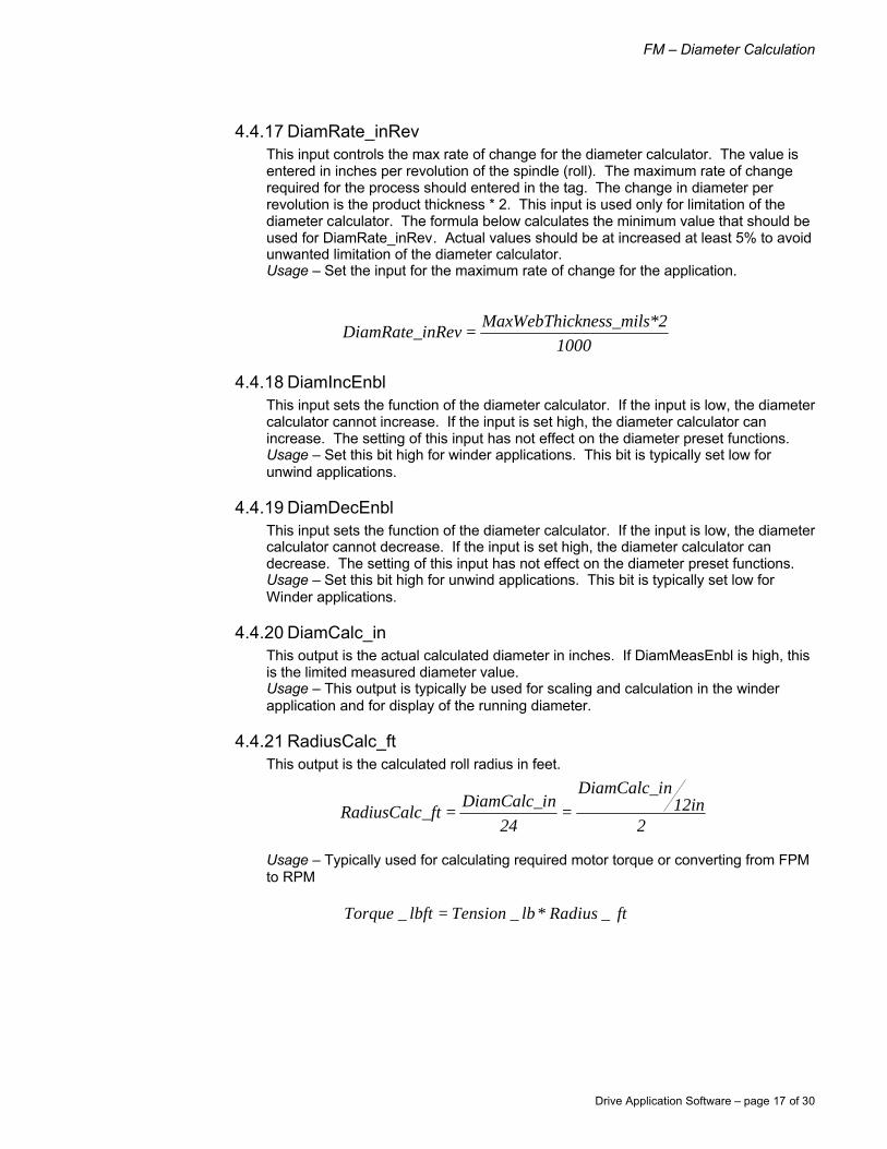
4.4.17 DiamRate_inRev This input controls the max rate of change for the diameter calculator. The value is entered in inches per revolution of the spindle (roll). The maximum rate of change required for the process should entered in the tag. The change in diameter per revolution is the product thickness * 2. This input is used only for limitation of the diameter calculator. The formula below calculates the minimum value that should be used for DiamRate_inRev. Actual values should be at increased at least 5% to avoid unwanted limitation of the diameter calculator. Usage – Set the input for the maximum rate of change for the application.
4.4.18 DiamIncEnbl This input sets the function of the diameter calculator. If the input is low, the diameter calculator cannot increase. If the input is set high, the diameter calculator can increase. The setting of this input has not effect on the diameter preset functions. Usage – Set this bit high for winder applications. This bit is typically set low for unwind applications.
4.4.19 DiamDecEnbl This input sets the function of the diameter calculator. If the input is low, the diameter calculator cannot decrease. If the input is set high, the diameter calculator can decrease. The setting of this input has not effect on the diameter preset functions. Usage – Set this bit high for unwind applications. This bit is typically set low for Winder applications.
4.4.20 DiamCalc_in This output is the actual calculated diameter in inches. If DiamMeasEnbl is high, this is the limited measured diameter value. Usage – This output is typically be used for scaling and calculation in the winder application and for display of the running diameter.
4.4.21 RadiusCalc_ft This output is the calculated roll radius in feet.
Usage – Typically used for calculating required motor torque or converting from FPM to RPM
1000*2kness_milsMaxWebThic
nRevDiamRate_i =
212in
nDiamCalc_i
24nDiamCalc_i
_ftRadiusCalc ==
ftRadiuslbTensionlbftTorque _*__ =

FM – Inertia Compensation
Drive Application Software – page 18 of 30
4.4.22 BuildUpRatio This output is a ratio of the actual diameter to the minimum empty core diameter.
Usage – Typically used to scale the spindle rotational speed reference.
4.4.23 BuildUpRatioRec This output is the reciprocal ratio of the actual diameter to the minimum empty core diameter.
Usage – Typically used to scale the spindle rotational speed reference.
4.4.24 DiamMeas_in This output is the scaled measured diameter from an external source. Usage – (default) This output is connected to the DiamPreset routine, for use as a preset to the diameter calculator.
4.4.25 Constant_RPMperFPM This output is created for use as a pre-calculated scaling constant. The constant is used in conversions from FPM linear speed ref to RPM motor speed. The change in roll diameter is not included in the constant and must be applied separately.
Usage – Use to convert speed in FPM to motor speed in RPM.
4.4.26 Constant_RPMperFPM This output is created to convert line speed values in FPM to the corresponding motor speed at minimum empty core diameter in RPM.
inDiamMinEC_nDiamCalc_i
ioBuildUpRat =
ioBuildUpRateedRef_RPMCoreLineSp
ed_RPMSpindleSpe =
tioRec*BuildUpRaeedRef_RPMCoreLineSped_RPMSpindleSpe =
nDiamCalc_iinDiamMinEC_
inDiamMinEC_nDiamCalc_i
1ioRecBuildUpRat ==
12*_ πinDiamMinEC
GearRatioPMperFPMConstant_R =
ioBuildUpRatPMnt_RPMperFFPM*ConstaLineSpeed_
_RPMMotorSpeed =

FM – Diameter Calculation
Drive Application Software – page 19 of 30
5.0 Setup / Configuration
5.1 Overview All setup and configuration is done in the Main routine. The Diameter Calculation Function Module is connected to the balance of the application software by placing application tag names in the Jump to Sub-Routine (JSR) instructions. One JSR is used to call the DiamPreset routine and a second JSR is used to call the DiamCalc routine. When JSR instruction input parameters are configured with tags, which are intended to be tuned by the user at commissioning, it is recommended that the (z prefix) naming convention be used for tags of this type.
5.2 DiamPreset JSR Instruction Note: If only a single diameter preset is required, the DiamPreset routine and JSR instruction can be deleted. If the DiamPreset routine is deleted, the (DiamCalc – In15 & In16) inputs [yDiamPresetCmmd] & [yDiamPresetVal_in] must be controlled by the user’s custom programming. If the diameter is not properly preset, the machine section may not be able to regulate product tension in the process.
5.2.1 Input Parameters
5.2.1.1 Preset1Cmmd – In 1, Preset2Cmmd – In 2, Preset3Cmmd – In 3 Enter application tags for the Preset Command input parameters (DiamPreset - In1, In2, and In3). Enter '0' for unused Preset Command input parameters.
5.2.1.2 DiamPreset1Val_in – In 4, DiamPreset2Val_in – In 5, DiamPreset3Val_in – In 6
Enter application tags for the Preset Value input parameters (DiamPreset - In4, In5, and In6). If the application tag values are not in units of inches, add a rung to the Main routine that will scale the tag values to inches. Enter '0.0' for unused Preset Value input parameters. Measured diameter can be used as a preset by configuring the tag used for the DiamCalc JSR instruction Measured Diameter return parameter (DiamCalc – Ret5) for one of the preset values.
5.2.1.3 PresetIncCmmd – In 7, PresetDecCmmd – In 8 Enter application tags for the Preset Increase/Decrease input parameters (DiamPreset - In7, In8). Enter '0' if Diameter Increase/Decrease function is not used.
5.2.1.4 PresetIncDecRate_inSec – In 9 Enter an application tag for the Preset Increase/Decrease Rate input parameter (DiamPreset - In9). If the application tag value is not in units of inches per second, add a rung to the Main routine that will scale the tag value to inches per second. If the preset increase/decrease function is not used, enter '0.0' for the Preset Increase/Decrease Rate input parameter.
5.2.2 Return Parameters
5.2.2.1 DiamPresetCmmd – Ret 1 Enter an application tag, for the Diameter Preset Command return parameter (DiamPreset - Ret1. This tag should be used in the DiamCalc JSR instruction input parameter (DiamCalc – In15).
5.2.2.2 DiamPresetVal_in – Ret 2 Enter an application tag, for Diameter Preset Value return parameter (DiamPreset – Ret2). This tag should be used in the DiamCalc JSR instruction input parameter (DiamCalc – In16).

FM – Inertia Compensation
Drive Application Software – page 20 of 30
5.2.3 Default Tags used in Drive Application Software
5.3 DiamCalc JSR Instruction
5.3.1 Input Parameters
5.3.1.1 CalcEnbl – In 1 Enter an application tag for the Diameter Calculator Enable input parameter (DiamCalc - In1). (See section 4 for guidelines on programming this tag.) If the Measured Diameter Input is always used, enter '0' for the Diameter Calculator Enable input parameter.
5.3.1.2 CalcEnblThresh_FPM – In 2, CalcUpdate_Rev – In 3 Enter an application tag for the Diameter Calculator Enable Threshold and the Diameter Calculator Update Interval input parameters (DiamCalc – In2, In3). If the Measured Diameter Input is always used, enter ‘0.0 for both the Diameter Calculator Threshold and the Diameter Calculator Update Interval. The Diameter Calculator Threshold and the Diameter Calculator Update Interval are typically configured with tags that can be tuned on-line.
5.3.1.3 LineSpeed _FPM – In 4 Enter an application tag for the Line Speed input parameter (DiamCalc - In4). If the application tag values are not in units of FPM and RPM, add a rung to the Main routine that will scale the tag values to FPM and RPM. (See section 4 for guidelines on programming these tags.)

FM – Diameter Calculation
Drive Application Software – page 21 of 30
5.3.1.4 SpeedMotor_RPM – In 5, GearRatio – In 6 Enter application tags for the Motor Speed and Gear Ratio input parameters (DiamCalc – In5, In6). The Gear Ratio is typically configured with a tag that can be tuned on-line. Since diameter rate is a function of Motor Speed and Gear Ratio, Motor Speed and Gear Ratio should always be configured.
5.3.1.5 DiamMinEC_in – In 7, DiamFR_in – In 8 Enter application tags for the Minimum Empty Core Diameter and Full Roll Diameter input parameters (DiamCalc – In7, In8). The Minimum Empty Core Diameter and Full Roll Diameter are typically configured with tags that can be tuned on-line. The Minimum Empty Core Diameter and Full Roll Diameter limit the magnitude of the Diameter Calculator return parameters. Build-Up Ratio is a function of Minimum Empty Core Diameter.
5.3.1.6 DiamMeasEnbl – In 9, DiamMeasInput – In 10, DiamMeasMin_DC – In 11, DiamMeasMax_DC – In 12, DiamMeasMin_in – In 13, DiamMeasMax_in – In 14
Enter application tags for Measured Diameter Enable, Measured Diameter Input [Data Counts], Minimum Measured Diameter [Data Counts], Maximum Measured Diameter [Data Counts], Minimum Measured Diameter [Inches], Maximum Measured Diameter [Inches] input parameters (DiamCalc – In9, In10, In11, In12, In13, In14). If a Measured Diameter signal is not used, enter ‘0’ for Measured Diameter Enable, ‘0.0’ for Measured Diameter Input, ‘1.0’ for both Minimum Measured Diameters, and ‘2.0’ for both Maximum Measured Diameters. When a Measured Diameter signal is used, Minimum and Maximum Diameter tags are typically configured with tags that can be tuned on-line.
5.3.1.7 DiamPresetCmmd In 15, DiamPreset Val_in – In 16 Enter application tags for Diameter Preset Command and Diameter Preset Value input parameters (DiamCalc – In15, In16). If the DiamPreset routine is used, enter the tags used as return parameters in the DiamPreset JSR instruction. If the DiamPreset routine is not used, enter the appropriate application tags. Measured diameter can be used as a preset by configuring the tag used for the Measured Diameter input parameter (DiamCalc – Ret5).
5.3.1.8 DiamRate_inRev – In 17, DiamIncEnbl – In 18, DiamDecEnbl – In 19 Enter application tags for Diameter Rate Limit, Diameter Calculator Increase Enable and Diameter Calculator Decrease Enable input parameters. These parameters are typically configured with tags that can be tuned on-line.
5.3.2 Return Parameters
5.3.2.1 DiamCalc_in – Ret 1, RadiusCalc_ft – Ret 2 Enter application tags, for the Calculated Diameter and Calculated Radius return parameters.
5.3.2.2 BuildUpRatio – Ret 3, BuildUpRatioRec – Ret 4 Enter application tags, for the Normalized Diameter and Reciprocal of Normalized Diameter return parameters (DiamCalc – Ret3, Ret4).
5.3.2.3 DiamMeas_in – Ret 5 Enter an application tag, for the Measured Diameter return parameter (DiamCalc – Ret5). If the Measured Diameter is used to preset the Diameter Calculator and the Diameter Preset routine is used, enter this tag name for the one of the Preset Value input parameters. If the Measured Diameter is used to preset the Diameter Calculator and the Diameter Preset routine is not used, enter this tag name for the Diameter Preset Value input parameter (DiamCalc – In16).
5.3.2.4 Constant_RPMperFPM – Ret 6 Enter an application tag, for the Calibration Constant return parameter.
FM – Inertia Compensation
Drive Application Software – page 22 of 30
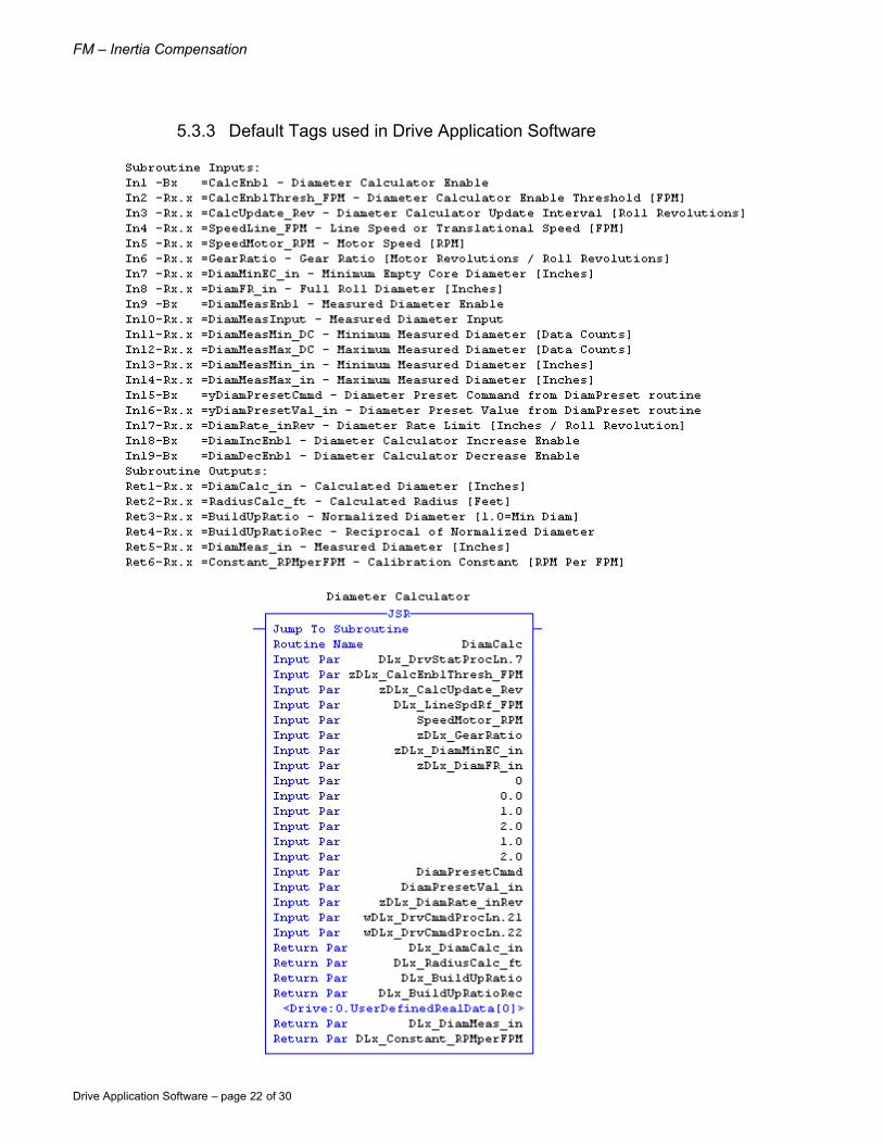
5.3.3 Default Tags used in Drive Application Software

FM – Diameter Calculation
Drive Application Software – page 23 of 30
6.0 Tuning / Startup
6.1 Installing the Application Module Perform the following operations in the order listed to ensure proper signal connections between the DriveLogix controller and the PowerFlex 700S firmware. 1. Download the RSLogix 5000 [.acd] file to the DriveLogix controller 2. Download the DriveExecutive [.dno] file to the PowerFlex 700S
Note, order of these events are critical as the DriveLogix controller must send the Peer Communication format to the PowerFlex 700S firmware before the PowerFlex 700S will accept all the configuration settings provided in the DriveExecutive file. Manually setting the Peer Communication format in the drive will not be effective until configured in DriveLogix. If this sequence of operation is not followed, the DriveLogix controller may not communicate with the PowerFlex 700S.
6.2 Drive Tuning & Configuration For basic commissioning of the application, the drive must first be tuned to regulate the motor. The following steps will guide you through the basic requirements of drive tuning when using an application module.
1. Set param 153 bit 8 high. This will set the start/stop control to 3 wire for operation via the HIM. When the start up is complete this must be set to low for 2 wire operation from DriveLogix.
2. From the HIM, select the “Start-Up” function and follow the directions. In this section you will perform the following steps.
a. Motor Control i. FOC – for Induction Motor ii. PMag – for Permanent Magnet Motor
b. Motor Data – Enter all motor data for the attached motor, check # poles c. Feedback Config – Select feedback type d. Pwr Circuit Diag e. Direction Test – (NOTE, the motor will run) recommend always changing
wires and not software, this is for maintenance purposes, if the program is restored it will default to the standard direction setting.
f. Motor Tests – (NOTE, the motor will run) g. Inertia Measure – (NOTE, the motor will run) h. Speed Limits
i. Select “+/- Speed Ref” ii. Fwd Speed Limit iii. Rev Speed Limit iv. Abs Overspd Lim – Max over speed past the Fwd and Rev
Speed Limit. This is where the drive will fault i. Do not complete the remainder of the Start-Up procedure in the drive j. Scroll down to “Done/Exit”
3. Tune the speed regulator. Depending on the inertia of the machine and other factors, the speed regulator bandwidth (param 90) should be set for 15 to 50 radians.
4. Set param 153 bit 8 Low. This will set the start/stop control to 2 wire for operation via DriveLogix

FM – Inertia Compensation
Drive Application Software – page 24 of 30
6.3 Offline Tuning / Startup Verify that the number and order of JSR input parameters and JSR return parameters agree with the JSR rung comment and section 4 of this user manual. Verify that the data type of all JSR instruction input and return parameters agree with the data type described in the JSR instruction rung comment and section 4 of this user manual. If immediate values are used for input parameters, the immediate value data type can be controlled by using or excluding a decimal point. For example, if the JSR instruction input parameter is designated as type REAL, and the desired value is zero, use “0.0” in the JSR instruction input parameter. An Input entered a “0” is used as an INTEGER value. Check the value of all JSR instruction input parameter tags. If the tag is calculated by other Logix instructions, verify that the tag will be calculated in the correct engineering units. If the tag is not calculated by other Logix instruction, preset the tag per section 4 of this user manual.
6.4 Online Tuning / Startup
6.4.1 Measured Diameter Enable True With the Logix controller in run, verify that the Measured Diameter return parameter (DiamCalc – Ret5) agrees with the actual diameter. If the Measured Diameter return parameter (DiamCalc – Ret5) is not accurate: 1. Check that the value of the following input parameters:
• Measured Diameter Input (DiamCalc - In10) • Minimum Measured Diameter (DiamCalc - In11) • Maximum Measured Diameter (DiamCalc - In12) • Minimum Measured Diameter (DiamCalc - In13) • Maximum Measured Diameter (DiamCalc - In14)
Preset the Diameter Calculator to the actual diameter drive (The diameter can only be preset with the Diameter Calculator Enable input parameter (DiamCalc – In1) false.) and run the drive (The diameter rate limit is zero when the motor speed is zero.) Verify that Calculated Diameter return parameter (DiamCalc - Ret1) tracks the actual diameter. If the Calculated Diameter return parameter (DiamCalc - Ret1) does not change with actual diameter: 1. Verify that the value of the Diameter Increase Enable, Diameter Decrease
Enable and the Diameter Rate Limit (DiamCalc – In17, In18, and In19) will allow the diameter to ramp to the measured value.
2. Verify that the Motor Speed and Gear Ratio input parameters (DiamCalc – In5, In6) are entered correctly.
6.4.2 Measured Diameter Enable False (typical configuration) Preset the Diameter Calculator to the actual diameter (the diameter can only be preset with the Diameter Calculator Enable input parameter (DiamCalc – In1) false). After diameter preset is complete, set the Diameter Calculator Enable input true. Run the drive at a line speed greater than the Diameter Calculator Enable Threshold (DiamCalc – In2). Verify that the Calculated Diameter return parameter (DiamCalc - Ret1) tracks the actual diameter. If the Calculated Diameter return parameter (DiamCalc - Ret1) does not change with actual diameter: 1. Verify that the Diameter Calculator Enable input parameter (DiamCalc – In1) is
true. 2. Verify that the value of the Diameter Increase Enable, Diameter Decrease Enable
and the Diameter Rate Limit (DiamCalc – In17, In18, and In19) will allow the diameter to ramp to the measured value.
3. Verify that the Motor Speed and Gear Ratio input parameters (DiamCalc – In5, In6) are entered correctly.

FM – Diameter Calculation
Drive Application Software – page 25 of 30
If the Calculated Diameter return parameter (DiamCalc - Ret1) is not accurate: 1. Hand tach the roll surface and verify that the correct value of Line Speed
(DiamCalc - In4). Finally, monitor motor speed and verify the correct value of Motor Speed (DiamCalc – In5).
Note: The diameter calculator is only as accurate as the Line Speed and Motor Speed input parameters (DiamCalc – In4, In5). For example, if a line speed reference signal is used for the Line Speed input parameter, lead section speed errors, lead section calibration errors, dancer loop velocity, and/or material stretch will contribute to differences between the actual surface speed of the roll and the Line Speed input parameter value. If the Calculated Diameter return parameter (DiamCalc - Ret1) is accurate but is fluctuating: 1. Increase the Diameter Calculator Update Interval (DiamCalc – In3) and use a
whole number of revolutions. Using a whole number of revolutions for the Diameter Calculator Update Interval will help reduce fluctuations due to roll eccentricity.

FM – Inertia Compensation
Drive Application Software – page 26 of 30
Appendix A - Process Line Command & Status Words
The following table is a functional list of the Process Line command word [wDLx_DrvCmmdProcLn]
Bit Input Signal Description 00 Clear Fault Clear all Faults 01 Run (2 Wire) 1 = Start, transition to 0 = Stop 02 Reserved 03 Coast Stop not supported in rev 110101 04 Jog Forward Jog in Forward direction 05 Jog Reverse Jog in Reverse direction 06 Reverse Rotation (Under Wind) Under wind selection 07 Tension Control Enable Activates selected mode of Tension Control
08 Stall Tension User determines how and when to activate Stall Tension
09 Tension Control Selects Tension Control Mode - Tension 10 Torque Control Selects Tension Control Mode - Torque 11 Dancer Control Selects Tension Control Mode - Dancer 12 Torque Trim Selects Trim type – Torque is trimmed 13 Speed Trim Selects Trim type – Speed is trimmed 14 Draw Trim Off Zeros the Draw trim signal 15 Torque Follower Control Special Control mode for torque follower 16 Diam Preset 1 Commands preset 1 for Diam Calc 17 Diam Preset 2 Commands preset 2 for Diam Calc 18 Diam Preset 3 Commands preset 3 for Diam Calc 19 Diam Preset Increase Manual increase for Diameter Calc 20 Diam Preset Decrease Manual decrease for Diameter Calc 21 Diam Calc Increase Enable Releases Diameter Clac for Increase 22 Diam Calc Decrease Enable Releases Diameter Calc for Decrease 23 Reserved 24 Reserved 25 Reserved 26 Reserved 27 Reserved 28 Reserved 29 Torque Mem Enable Memorizes running torque
30 Torque Mem Boost Enable Boosts the memorized torque by user set percentage.
31 Torque Mem Knife Cut Boosts the memorized torque by user set percentage.

FM – Diameter Calculation
Drive Application Software – page 27 of 30
The following table is a functional list of the Process Line status word [DLx_DrvStatProcLn]
Bit Output Signal Description 00 Fault Drive Fault or a System Fault 01 Running Drive is Running / not stopping 02 Reserved 03 Motor Ctrl On Motor is being control (Motor POWER) 04 Reserved 05 Jogging section Jogging 06 Rotational Reverse Under Wind 07 Tension Control On Selected mode of Tension control is enabled 08 Zero Speed Below Zero Line speed set point 09 Diameter Calculation Active Future 10 Reserved 11 Reserved 12 Reserved 13 Reserved 14 Reserved 15 Reserved 16 Enable Loss Fault Drive Enable lost 17 Fail to Run fault Drive failed to start 18 Communication fault NA – not support 19 Message fault NA – not support 20 Motor Overload Fault Overload alarm from drive 21 Motor Overtemperature Flt Over temperature alarm from drive 22 Motor Blower Loss Fault Motor blower has stopped or tripped off 23 Reserved 24 Reserved 25 Reserved 26 Reserved 27 Reserved 28 Reserved 29 Reserved
30 Operate Permissive Use in line control logic to command a coordinated line ramp stop.
31 On Permissive Loss of permissive resets start command. The drive will coast stop or ramp stop depending on configuration

FM – Inertia Compensation
Drive Application Software – page 28 of 30
Appendix B - Block Diagram
>&
CalcE
nabl
eThr
esh_
FPM
Line
Spee
dRef
_FPM
Calcu
lato
r Ena
ble
Diam
CalcA
vtive
Line
Spee
dRef
_FPM
12X
/
RollS
peed
_RPM
/
3.14
Ram
p
0 0
Diam
IncE
nabl
e
Diam
DecE
nabl
e
0 0
RollS
peed
_FPM
Diam
Rate
_inR
ev
+ -
* /
Diam
Calc_
in0
0
Diam
Pres
etCm
md
Diam
Pres
etVa
l_in
Diam
Mea
sure
d_in
Diam
Mea
sEnb
l
11
11
DIV_
03.D
est
& &

FM – Diameter Calculation
Drive Application Software – page 29 of 30
Appendix C - Parameter (Tag) Table Input Tags for Diameter Calculation Function Module
Name Type Source Tag from Routine Default User Value
DiamPreset – Routine Preset1Cmmd B x wDLx_DrvCmmdProcLn.16 NA 0
Preset2Cmmd B x wDLx_DrvCmmdProcLn.17 NA 0
Preset3Cmmd B x wDLx_DrvCmmdProcLn.18 NA 0
Preset1Val_in R x.x zDLx_DiamPreset1Val_in NA 4.0
Preset2Val_in R x.x zDLx_DiamPreset2Val_in NA 6.0
Preset3Val_in R x.x zDLx_DiamPreset2Val_in NA 9.0
PresetIncCmmd B x wDLx_DrvCmmdProcLn.19 NA 0
PresetDecCmmd B x wDLx_DrvCmmdProcLn.19 NA 0
PresetIncDecRate_inSec R x.x zDLx_DiamPresetIncDecRate_ inSec
NA 0.0
DiamCalc – Routine CalcEnbl B x DLx_DrvStatProcLn.7 NA 0
CalcEnblThresh_FPM R x.x zDLx_CalcEnblThresh_FPM NA 5.0
CalcUpdate_Rev R x.x zDLx_CalcUpdate_Rev NA 2.0
SpeedLine_FPM R x.x DLx_LineSpdRf_FPM RunJogSpdRf NA
SpeedMotor_RPM R x.x SpeedMotor_RPM Main – scaled to (RPM) NA
GearRatio R x.x zDLx_GearRatio NA 5.0
DiamMinEC_in R x.x zDLx_DiamMinEC_in NA 4.0
DiamFR_in R x.x zDLx_DiamFR_in NA 30.0
DiamMeasEnbl B x None NA 0
DiamMeasInput R x.x None NA 0.0
DiamMeasMin_DC R x.x None NA 1.0
DiamMeasMax_DC R x.x None NA 2.0
DiamMeasMin_in R x.x None NA 1.0
DiamMeasMax_in R x.x None NA 2.0
yDiamPresetCmmd B x DiamPresetCmmd DiamPreset NA
yDiamPresetVal_in R x.x DiamPresetVal_in DiamPreset NA
DiamRate_inRev R x.x zDLx_DiamRate_inRev NA 0.25
DiamIncEnbl B x wDLx_DrvCmmdProcLn.21 NA 0
DiamDecEnbl B x wDLx_DrvCmmdProcLn.22 NA 0

www.rockwellautomation.com for Drive Application Software www.ab.com/drives/drvappsw Corporate Headquarters Rockwell Automation, 777 East Wisconsin Avenue, Suite 1400, Milwaukee, WI, 53202-5302 USA, Tel: (1) 414.212.5200, Fax: (1) 414.212.5201 Headquarters for Allen-Bradley Products, Rockwell Software Products and Global Manufacturing Solutions Americas: Rockwell Automation, 1201 South Second Street, Milwaukee, WI 53204-2496 USA, Tel: (1) 414.382.2000, Fax: (1) 414.382.4444 Europe: Rockwell Automation SA/NV, Vorstlaan/Boulevard du Souverain 36-BP 3A/B, 1170 Brussels, Belgium, Tel: (32) 2 663 0600, Fax: (32) 2 663 0640 Asia Pacific: Rockwell Automation, 27/F Citicorp Centre, 18 Whitfield Road, Causeway Bay, Hong Kong, Tel: (852) 2887 4788, Fax: (852) 2508 1846 Headquarters for Dodge and Reliance Electric Products Americas: Rockwell Automation, 6040 Ponders Court, Greenville, SC 29615-4617 USA, Tel: (1) 864.297.4800, Fax: (1) 864.281.2433 Europe: Rockwell Automation, Brühlstraße 22, D-74834 Elztal-Dallau, Germany, Tel: (49) 6261 9410, Fax: (49) 6261 17741 Asia Pacific: Rockwell Automation, 55 Newton Road, #11-01/02 Revenue House, Singapore 307987, Tel: (65) 351 6723, Fax: (65) 355 1733 U.S. Allen-Bradley Drives Technical Support Tel: (1) 262.512.8176, Fax: (1) 262.512.2222, Email: [email protected], Online: www.ab.com/support/abdrives Publication: 9329-RM001B-EN-E March 2003
Copyright © 2003 Rockwell Automation. All rights reserved. Printed in USA